Adaptive Solutions with Cisco UCS X215c M8 and Hitachi VSP One Block E2E 100G VMware
Available Languages
Bias-Free Language
The documentation set for this product strives to use bias-free language. For the purposes of this documentation set, bias-free is defined as language that does not imply discrimination based on age, disability, gender, racial identity, ethnic identity, sexual orientation, socioeconomic status, and intersectionality. Exceptions may be present in the documentation due to language that is hardcoded in the user interfaces of the product software, language used based on RFP documentation, or language that is used by a referenced third-party product. Learn more about how Cisco is using Inclusive Language.
- US/Canada 800-553-2447
- Worldwide Support Phone Numbers
- All Tools
 Feedback
 Feedback
In partnership with:

About the Cisco Validated Design Program
The Cisco Validated Design (CVD) program consists of systems and solutions designed, tested, and documented to facilitate faster, more reliable, and more predictable customer deployments. For more information, go to: http://www.cisco.com/go/designzone.
Executive Summary
Cisco Validated Designs consist of systems and solutions that are designed, tested, and documented to facilitate and improve customer deployments. These designs incorporate a wide range of technologies and products into a portfolio of solutions that have been developed to address the business needs of our customers.
Cisco and Hitachi have joined forces to provide a converged infrastructure solution designed to address the current challenges faced by enterprise businesses and to position them for future success. Drawing upon their extensive industry knowledge and innovative technology, this collaborative Cisco CVD presents a robust, flexible, and agile foundation for today's businesses. Moreover, the partnership between Cisco and Hitachi goes beyond a singular solution, allowing businesses to leverage their ambitious roadmap of progressive technologies, including advanced analytics, IoT, cloud, and edge capabilities. By partnering with Cisco and Hitachi, organizations can confidently embark on their modernization journey and position themselves to capitalize on emerging business opportunities facilitated by groundbreaking technology.
This document explains the deployment of the Cisco and Hitachi Adaptive Solutions for Converged Infrastructure as a Virtual Server Infrastructure (VSI), as it was described in the Adaptive Solutions with Cisco UCS X215c M8 and Hitachi VSP One Block E2E 100G VMware Design Guide. The recommended solution architecture is built on Cisco Unified Computing System (Cisco UCS) using the unified software release to support the Cisco UCS hardware platforms for Cisco UCS X-Series servers, Cisco UCS X-Series Direct Fabric Interconnects, Cisco Nexus 9000 Series switches, and the Hitachi Virtual Storage Platform (VSP) One Block 24 using high-performance NVMe over TCP-delivered storage. This architecture is implemented on VMware vSphere 8.0U3 to support the leading virtual server platform for enterprise customers.
Additional Cisco Validated Designs created in a partnership between Cisco and Hitachi can be found here: https://cisco.com/go/as-cvds
Solution Overview
This chapter contains the following:
● Audience
Modernizing your data center can be overwhelming, and it’s vital to select a trusted technology partner with proven expertise. With Cisco and Hitachi as partners, companies can build for the future by enhancing systems of record, supporting systems of innovation, and growing their business. Organizations need an agile solution, free from operational inefficiencies, to deliver continuous data availability, meet SLAs, and prioritize innovation.
Cisco and Hitachi Adaptive Solutions for Converged Infrastructure as a Virtual Server Infrastructure (VSI) is a best-practice datacenter architecture built on the collaboration of Hitachi Vantara and Cisco to meet the needs of enterprise customers running virtual server workloads. This architecture is composed of the Hitachi VSP One Block series connected through the Cisco Nexus 9300 switches, supporting the NVMe over TCP (NVMe/TCP) storage protocol, to Cisco Unified Computing System X-Series Servers managed through Cisco Intersight.
These deployment instructions are based on the buildout of the Cisco and Hitachi Adaptive Solutions for Converged Infrastructure validated reference architecture, which describes the specifics of the products used within the Cisco validation lab, but the solution is considered relevant for equivalent supported components listed within Cisco and Hitachi Vantara’s published compatibility matrices. Supported adjustments from the example validated build must be evaluated with care, as their implementation instructions may differ.
The intended audience of this document includes, but is not limited to, IT architects, sales engineers, field consultants, professional services, IT managers, partner engineering, and customers who want to take advantage of an infrastructure built to deliver IT efficiency and enable IT innovation.
This document provides a step-by-step configuration and implementation guide for the Cisco and Hitachi Adaptive Solutions for the Converged Infrastructure solution. This solution features a validated reference architecture composed of:
● Cisco UCS Compute
● Cisco Nexus Switches
● Hitachi Virtual Storage Platform
For the design decisions and technology discussion of the solution, see the Adaptive Solutions with Cisco UCS X215c M8 and Hitachi VSP One Block E2E 100G VMware Design Guide
The following design elements distinguish this version of the Adaptive Solutions Virtual Server Infrastructure from previous models:
● Cisco UCS X215c M8 servers with 5th Gen AMD EPYCTM processors, supporting up to 96 cores per processor and up to 6TB of DDR5-6400 DIMMs
● 100 Gbps Ethernet end-to-end
● Integration of the Cisco UCS X-Series Direct 9108-100G Fabric Interconnect into Adaptive Solutions
● VMware vSphere 8.0 Update 3g
● NVMe/TCP connectivity to the Hitachi VSP One storage array providing VMFS datastores
● M.2 boot LUNs
● Hitachi Virtual Storage Platform (VSP) One Block 24
● Hitachi Vantara VSP One Block Storage Modules for Red Hat Ansible
Deployment Hardware and Software
This chapter contains the following:
The Adaptive Solutions Virtual Server Infrastructure consists of a high-performance network built using the following hardware components:
● Cisco UCS X9508 Chassis with Cisco UCS X-Series Direct Fabric Interconnect, supporting (8/16/32 Gbps) Fibre Channel connectivity, 10/25/40/100 Gigabit Ethernet, and up to eight Cisco UCS X215c M8 Compute Nodes with 4th or 5th Generation AMD EPYCTM CPUs.
● High-speed Cisco NX-OS-based Nexus 93600CD-GX switching design supporting up to 400G.
● Hitachi VSP One Block with 100G NVMe/TCP connectivity.
The software components of the solution consist of:
● Cisco Intersight SaaS platform to deploy, maintain, and support the Adaptive Solutions infrastructure.
● Cisco Intersight Assist Virtual Appliance to connect the Hitachi VSP One Block, VMware vCenter, and Cisco Nexus switches with Cisco Intersight.
● VMware vCenter to set up and manage the virtual infrastructure, as well as Cisco Intersight integration.
● Hitachi VSP One Block Administrator.
● Hitachi Vantara’s Command Control Interface (CCI) Raidcom software, which serves as the primary method to configure the IP storage protocols of the VSP One Block.
● Hitachi Vantara VSP One Block Storage Modules for Red Hat Ansible.
Figure 1 shows the validated hardware components and connections used in the Adaptive Solutions Virtual Server Infrastructure design.
The reference hardware configuration includes:
● Two Cisco Nexus 93600CD-GX switches in Cisco NX-OS mode, providing the switching fabric.
● Two Cisco UCS X-Series Direct Fabric Interconnects (FIs), providing chassis connectivity. One 100 Gigabit Ethernet port from each FI, configured as a Port-Channel, is connected to each 93600CD-GX.
● Hitachi VSP One Block controllers, each connecting with one 100 Gbps NVMe/TCP port to each Cisco Nexus 93600CD-GX switch, delivering traffic to the IP SAN network.
Table 1 lists the software revisions for various components of the solution.
| Layer |
Device |
Image |
Comments |
| Network |
Cisco Nexus 93600CD-GX NX-OS |
10.4(5)M |
|
| Compute |
Cisco UCS X-Direct 9108-100G Fabric Interconnect |
4.3(5.250033) |
|
| Cisco UCS X215c M8 |
5.3(0.250001) |
|
|
| Cisco UCS Tools |
1.4.3 |
|
|
| VMware ESXi nenic Ethernet Driver |
2.0.15.0 |
|
|
| VMware ESXi |
8.0 Update 3g |
Build 24859861 |
|
| VMware vCenter Appliance |
8.0 Update 3e |
Build 24674346 |
|
| Cisco Intersight Assist Appliance |
1.1.2-0 |
1.1.2-0 initially installed; will be automatically upgraded as new releases become available. |
|
| Storage |
Hitachi VSP One Block |
SVOS 10.4.0 A3-04-02-40/00 |
|
| Hitachi Vantara VSP One Block Storage Modules for Red Hat Ansible |
VSP One Block Storage Modules 3.5 Red Hat Enterprise Linux 8.10 Ansible-Core 2.16.3 |
|
Table 2 lists the VLANs configured in the environment and details their usage.
| VLAN ID |
Name |
Usage |
IP Subnet used in this deployment |
| 2 |
Native-VLAN |
Use VLAN 2 as the native VLAN instead of the default VLAN (1). |
|
| 19 |
OOB-MGMT-VLAN |
Out-of-band management VLAN to connect management ports for various devices. |
192.168.168.0/24; GW: 192.168.168.254** |
| 41 |
NVMe-TCP-A |
Fabric A NVMe over TCP traffic |
10.0.41.0/24* |
| 42 |
NVMe-TCP-B |
Fabric B NVMe over TCP traffic |
10.0.42.0/24* |
| 119 |
IB-MGMT-VLAN |
In-band management VLAN used for all in-band management connectivity, for example, ESXi hosts, VM management, and others. |
10.1.168.0/24; GW: 10.1.168.254 |
| 1000 |
vMotion |
VMware vMotion traffic |
10.0.0.0/24* |
| 1100 |
VM-Traffic |
VM data traffic sourced from FI-A and FI-B |
10.1.100.0/24; GW: 10.1.100.254 |
| 1101 |
VM-Traffic-A |
VM data traffic sourced from FI-A |
10.1.101.0/24; GW: 10.1.101.254 |
| 1102 |
VM-Traffic-B |
VM data traffic sourced from FI-B |
10.1.101.0/24; GW: 10.1.101.254 |
* IP gateway is not required for these subnets as no routing is used.
** OB-MGMT-VLAN is not carried on the FI uplinks and will not be part of the VLAN Policy.
Table 3 lists the infrastructure VMs necessary for the VSI environment hosted on pre-existing management infrastructure.
| Virtual Machine Description |
VLAN |
IP Address |
| Cisco Intersight Assist |
119 |
10.1.168.99 |
| vCenter Server |
119 |
10.1.168.150 |
| Active Directory |
119 |
10.1.168.101 |
The information in this section is provided as a reference for cabling the physical equipment in the environment. This includes a diagram and tables for each layer of infrastructure, detailing the local and remote port locations.
Note: If you modify the validated architecture, see the Cisco Hardware Compatibility Matrix and the Hitachi Product Compatibility Guide for guidance.
This document assumes that the out-of-band management ports are plugged into an existing management infrastructure at the deployment site. These interfaces will be used in various configuration steps.
Figure 2 details the cable connections used in the validation lab for the Adaptive Solutions VSI topology based on the Cisco UCS X-Series Direct 9108-100G Fabric Interconnect and the Hitachi VSP One. 100G links connect the Cisco UCS Fabric Interconnects as port-channels to the Cisco Nexus 93600CD-GX switch pair’s vPCs, with 100G connections from the Nexus switches to the VSP connecting as unbundled ports. Upstream of the Nexus switches, 400G uplink connections are possible for this model, but are not present in this design.
Additional 1Gb management connections are required for an out-of-band network switch that sits apart from the Adaptive Solutions infrastructure. Each Cisco UCS fabric interconnect and Cisco Nexus switch is connected to the out-of-band network switch, and the VSP has two controllers. Each VSP controller has a connection to the out-of-band network switch. Layer 3 network connectivity is required between the Out-of-Band (OOB) and In-Band (IB) management subnets.
Tables 4 through 9 list the specifics of the connections for each component.
Table 4. Cisco Nexus 93600CD-GX A Cabling Information
| Local Device |
Local Port |
Connection |
Remote Device |
Remote Port |
| Cisco Nexus 93600CD-GX A |
1/7 |
QSFP-100G-AOC2M |
Cisco UCS X-Series Direct FI A |
1/7 |
| 1/8 |
QSFP-100G-AOC2M |
Cisco UCS X-Series Direct FI B |
1/7 |
|
| 1/13 |
QSFP-100G-SR4 |
Hitachi VSP One Block |
CL1-D |
|
| 1/14 |
QSFP-100G-SR4 |
Hitachi VSP One Block |
CL2-D |
|
| 1/29 |
QSFP-100G-AOC1M |
Cisco Nexus 93600CD-GX B |
1/29 |
|
| 1/30 |
QSFP-100G-AOC1M |
Cisco Nexus 93600CD-GX B |
1/30 |
|
| 1/36 |
10Gbase-SR |
Upstream Network |
|
|
| Mgmt |
Cat 5 |
Management Switch |
|
Table 5. Cisco Nexus 93600CD-GX B Cabling Information
| Local Device |
Local Port |
Connection |
Remote Device |
Remote Port |
| Cisco Nexus 93600CD-GX B
|
1/7 |
QSFP-100G-AOC2M |
Cisco UCS X-Series Direct FI A |
1/8 |
| 1/8 |
QSFP-100G-AOC2M |
Cisco UCS X-Series Direct FI B |
1/8 |
|
| 1/13 |
QSFP-100G-SR4 |
Hitachi VSP One Block |
CL3-D |
|
| 1/14 |
QSFP-100G-SR4 |
Hitachi VSP One Block |
CL4-D |
|
| 1/29 |
QSFP-100G-AOC1M |
Cisco Nexus 93600CD-GX A |
1/29 |
|
| 1/30 |
QSFP-100G-AOC1M |
Cisco Nexus 93600CD-GX A |
1/30 |
|
| 1/36 |
10Gbase-SR |
Upstream Network |
|
|
| Mgmt |
Cat 5 |
Management Switch |
|
Table 6. Cisco UCS X-Series Direct Fabric Interconnect A Cabling Information
| Local Device |
Local Port |
Connection |
Remote Device |
Remote Port |
| Cisco UCS X-Series Direct FI A
|
1/7 |
QSFP-100G-AOC2M |
Cisco Nexus 93600CD-GX A |
1/7 |
| 1/8 |
QSFP-100G-AOC2M |
Cisco Nexus 93600CD-GX B |
1/7 |
|
| Mgmt |
Cat 5 |
Management Switch |
|
Table 7. Cisco UCS X-Series Direct Fabric Interconnect B Cabling Information
| Local Device |
Local Port |
Connection |
Remote Device |
Remote Port |
| Cisco UCS X-Series Direct FI B
|
1/1 |
QSFP-100G-AOC2M |
Cisco Nexus 93600CD-GX A |
1/8 |
| 1/2 |
QSFP-100G-AOC2M |
Cisco Nexus 93600CD-GX B |
1/8 |
|
| Mgmt |
Cat 5 |
Management Switch |
|
Table 8. Hitachi VSP One Block Controller 1
| Local Device |
Local Port |
Connection |
Remote Device |
Remote Port |
| Hitachi VSP One Block Controller 1
|
1D |
FTLF8564D1BCW |
Cisco Nexus 93600CD-GX A |
1/13 |
| 3D |
FTLF8564D1BCW |
Cisco Nexus 93600CD-GX B |
1/13 |
|
| Mgmt |
Cat 5 |
Management Switch |
|
Table 9. Hitachi VSP One Block Controller 2
| Local Device |
Local Port |
Connection |
Remote Device |
Remote Port |
| Hitachi VSP One Block Controller 2
|
4D |
FTLF8564D1BCW |
Cisco Nexus 93600CD-GX A |
1/14 |
| 2D |
FTLF8564D1BCW |
Cisco Nexus 93600CD-GX B |
1/14 |
|
| Mgmt |
Cat 5 |
Management Switch |
|
The cables and transceivers used in the validated environment are examples of supported connections and are not prescriptive to the solution. They demonstrate a set of valid options for this design. For additional supported transceivers and cable types, see the specific product specification sheets and the Cisco Optics-to-Device Compatibility Matrix here: https://tmgmatrix.cisco.com/.
Cisco Nexus LAN Switch Configuration
This chapter contains the following:
● Cisco Nexus Switch Configuration
This chapter provides detailed procedures for configuring the Cisco Nexus 93600CD-GX switches for use in the LAN switching of the Adaptive Solutions Virtual Server Infrastructure.
Follow the physical connectivity guidelines for infrastructure cabling as explained in the Adaptive Solutions Cabling section.
The following procedures describe this basic configuration of the Cisco Nexus switches for use in the Adaptive Solutions VSI. These procedures assume the use of Cisco Nexus 9000 10.4(5)M, the Cisco suggested Nexus switch release at the time of this validation. If not at version 10.4(5)M, the switches can be upgraded after initial configuration by following the Cisco Nexus 9000 Series NX-OS Software Upgrade and Downgrade Guide, Release 10.4(x).
Procedure 1. Set up Initial Configuration
To set up the initial configuration for the Cisco Nexus A switch on <nexus-A-hostname>, follow these steps from a serial console:
Step 1. Configure the switch:
Note: On initial boot, the NX-OS setup should automatically start and attempt to enter Power on Auto Provisioning.
Abort Power On Auto Provisioning [yes - continue with normal setup, skip - bypass password and basic configuration, no - continue with Power On Auto Provisioning] (yes/skip/no)[no]: yes
Disabling POAP.......Disabling POAP
poap: Rolling back, please wait... (This may take 5-15 minutes)
---- System Admin Account Setup ----
Do you want to enforce secure password standard (yes/no) [y]: Enter
Enter the password for "admin": <password>
Confirm the password for "admin": <password>
Would you like to enter the basic configuration dialog (yes/no): yes
Create another login account (yes/no) [n]: Enter
Configure read-only SNMP community string (yes/no) [n]: Enter
Configure read-write SNMP community string (yes/no) [n]: Enter
Enter the switch name: <nexus-A-hostname>
Continue with Out-of-band (mgmt0) management configuration? (yes/no) [y]: Enter
Mgmt0 IPv4 address: <nexus-A-out_of_band_mgmt0-ip>
Mgmt0 IPv4 netmask: <nexus-A-mgmt0-netmask>
Configure the default gateway? (yes/no) [y]: Enter
IPv4 address of the default gateway: <nexus-A-mgmt0-gw>
Configure advanced IP options? (yes/no) [n]: Enter
Enable the telnet service? (yes/no) [n]: Enter
Enable the ssh service? (yes/no) [y]: Enter
Type of ssh key you would like to generate (dsa/rsa) [rsa]: Enter
Number of rsa key bits <1024-2048> [1024]: Enter
Configure the ntp server? (yes/no) [n]: Enter
Configure default interface layer (L3/L2) [L2]: Enter
Configure default switchport interface state (shut/noshut) [noshut]: shut
Enter basic FC configurations (yes/no) [n]: n
Configure CoPP system profile (strict/moderate/lenient/dense) [strict]: Enter
Would you like to edit the configuration? (yes/no) [n]: Enter
Step 2. Review the configuration summary before enabling the configuration:
Use this configuration and save it? (yes/no) [y]: Enter
Step 3. To set up the initial configuration of the Cisco Nexus B switch, repeat steps 1 and 2 with the appropriate host and IP address information.
Cisco Nexus Switch Configuration
To manually configure the Nexus switches, follow these steps:
Procedure 1. Enable Nexus Features
Cisco Nexus A and Cisco Nexus B. Perform these steps on both switches.
Step 1. Log in as admin using ssh.
Step 2. Run the following commands to enable Nexus features:
config t
feature nxapi
feature hsrp
feature udld
feature interface-vlan
feature lacp
feature vpc
feature lldp
Procedure 2. Set Global Configurations
Cisco Nexus A and Cisco Nexus B
Note: Perform these steps on both switches.
Step 1. Run the following commands to set global configurations:
spanning-tree port type network default
spanning-tree port type edge bpduguard default
spanning-tree port type edge bpdufilter default
port-channel load-balance src-dst l4port
ip name-server <dns-server-1> <dns-server-2>
ip domain-name <dns-domain-name>
ip domain-lookup
ntp server <global-ntp-server-ip> use-vrf management
ntp master 3
clock timezone <timezone> <hour-offset> <minute-offset>
For example: clock timezone EST -5 0:
clock summer-time <timezone> <start-week> <start-day> <start-month> <start-time> <end-week> <end-day> <end-month> <end-time> <offset-minutes>
For example: clock summer-time EDT 2 Sunday March 02:00 1 Sunday November 02:00 60:
copy run start
ip route 0.0.0.0/0 <oob-mgmt-vlan-gateway>
Note: For more information on configuring the timezone and daylight savings time or summer time, see Cisco Nexus 9000 Series NX-OS Fundamentals Configuration Guide, Release 10.4(x).
Procedure 3. Create VLANs
Cisco Nexus A and Cisco Nexus B
Note: Perform these steps on both switches.
Step 1. From the global configuration mode, run the following commands:
vlan <native-vlan-id for example, 2>
name native-vlan
vlan <nvme-tcp-a-vlan-id for example, 41> #Fab A Only
name nvme-tcp-a
vlan <nvme-tcp-b-vlan-id for example, 42> #Fab B Only
name nvme-tcp-b
vlan <ib-mgmt-vlan-id for example, 119>
name ib-mgmt
vlan <vmotion-vlan-id for example, 1000>
name vmotion
vlan <vm-traffic-vlan-id for example, 1100>
name vm-traffic
vlan <vm-traffic-a-vlan-id for example, 1101>
name vm-traffic-a
vlan <vm-traffic-b-vlan-id for example, 1102>
name vm-traffic-b
Procedure 4. Add NTP Distribution Interface in IB-MGMT Subnet (Optional)
This procedure will configure each IB-MGMT SVI to be available for redistribution of the NTP service to optionally configured application networks that might not be set up to reach an upstream NTP source.
Cisco Nexus A
Step 1. From the global configuration mode, run the following commands:
interface Vlan<ib-mgmt-vlan-id>
ip address <switch-a-ntp-ip>/<ib-mgmt-vlan-netmask-length>
no shutdown
exit
ntp peer <nexus-B-mgmt0-ip> use-vrf management
Cisco Nexus B
Step 1. From the global configuration mode, run the following commands:
interface Vlan<ib-mgmt-vlan-id>
ip address <switch-b-ntp-ip>/<ib-mgmt-vlan-netmask-length>
no shutdown
exit
ntp peer <nexus-A-mgmt0-ip> use-vrf management
Procedure 5. Create Application Network Interfaces (Optional)
This procedure creates Switched Virtual Interfaces (SVI) and Hot Standby Router Protocol (HSRP) configurations for each of these SVIs. The HSRP relationship allows an active/standby relationship between the two Nexus switches for these interfaces. The IB-Mgmt network is implemented for routing upstream of the Nexus switches, and these application networks could similarly be handled.
Cisco Nexus A
Step 1. Run the following commands:
int vlan 1100
no shutdown
ip address <<var_nexus_A_App-1100>>/24
hsrp 100
preempt
ip <<var_nexus_App-1100_vip>>
Note: When HSRP priority is not set, it defaults to 100. Alternating SVIs within a switch are set to a number higher than 105 to set those SVIs to default to be the standby router for that network. Be careful when the VLAN SVI for one switch is set without a priority (defaulting to 100), the partner switch is set to a priority with a value other than 100.
Cisco Nexus B
Step 1. Run the following commands:
int vlan 1100
no shutdown
ip address <<var_nexus_B_App-1100>>/24
hsrp 100
preempt
priority 105
ip <<var_nexus_App-1100_vip>>
Procedure 6. Create Port Channels
Cisco Nexus A
Note: For fibre optic connections to Cisco UCS systems (AOC or SFP-based), entering udld enable will result in a message stating that this command is not applicable to fiber ports. This message is expected. This command will enable UDLD on twinax connections.
Step 1. From the global configuration mode, run the following commands:
interface Po10
description vPC peer-link
!
interface Eth1/29
description <nexus-b-hostname>:Eth1/29
!
interface Eth1/30
description <nexus-b-hostname>:Eth1/30
!
interface Eth1/29-30
channel-group 10 mode active
no shutdown
!
! UCS Connectivity
!
interface Po17
description <ucs-domainname>-a
!
interface Eth1/7
udld enable
description <ucs-domainname>-a:Eth1/7
channel-group 17 mode active
no shutdown
!
interface Po18
description <ucs-domainname>-b
!
interface Eth1/8
udld enable
description <ucs-domainname>-b:Eth1/7
channel-group 18 mode active
no shutdown
!
interface Eth1/13
description <vsp>-CL1-D 100G
switchport access vlan <nvme-tcp-a-vlan>
mtu 9216
no shutdown
!
interface Eth1/14
description <vsp>-CL2-D 100G
switchport access vlan <nvme-tcp-a-vlan>
mtu 9216
no shutdown
!
! Uplink Switch Connectivity
!
interface Po136
description MGMT-Uplink
!
interface Eth1/36
description <mgmt-uplink-switch-a-hostname>:<port>
channel-group 136 mode active
no shutdown
exit
copy run start
Cisco Nexus B
Note: For fibre optic connections to Cisco UCS systems (AOC or SFP-based), entering “udld enable” will result in a message stating that this command is not applicable to fiber ports. This message is expected. This command will enable UDLD on twinax copper connections.
Step 1. From the global configuration mode, run the following commands:
interface Po10
description vPC peer-link
!
interface Eth1/29
description <nexus-a-hostname>:Eth1/29
!
interface Eth1/30
description <nexus-a-hostname>:Eth1/30
!
interface Eth1/29-30
channel-group 10 mode active
no shutdown
!
! UCS Connectivity
!
interface Po17
description <ucs-domainname>-a
!
interface Eth1/7
udld enable
description <ucs-domainname>-a:Eth1/8
channel-group 17 mode active
no shutdown
!
interface Po18
description <ucs-domainname>-b
!
interface Eth1/8
udld enable
description <ucs-domainname>-b:Eth1/8
channel-group 18 mode active
no shutdown
!
interface Eth1/13
description <vsp>-CL3-D 100G
switchport access vlan <nvme-tcp-b-vlan>
mtu 9216
no shutdown
!
interface Eth1/14
description <vsp>-CL4-D 100G
switch port access vlan <nvme-tcp-b-vlan>
mtu 9216
no shutdown
!
! Uplink Switch Connectivity
!
interface Po136
description MGMT-Uplink
!
interface Eth1/36
description <mgmt-uplink-switch-a-hostname>:<port>
channel-group 136 mode active
no shutdown
exit
copy run start
Procedure 7. Configure Port Channel Parameters
Cisco Nexus A and Cisco Nexus B. Perform these steps on both switches.
Step 1. From the global configuration mode, run the following commands to set up the VPC Peer-Link port-channel:
interface Po10
switchport mode trunk
switchport trunk native vlan <native-vlan-id>
switchport trunk allowed vlan <nvme-tcp-a-vlan>,<nvme-tcp-b-vlan>,<ib-mgmt-vlan >,<vmotion-vlan>,<vm-traffic-vlan>,<vm-traffic-a-vlan>,<vm-traffic-b-vlan>
spanning-tree port type network
speed 100000
duplex full
Step 2. From the global configuration mode, run the following commands to set up port-channels for UCS FI X-Direct connectivity:
interface Po17
switchport mode trunk
switchport trunk native vlan <native-vlan-id>
switchport trunk allowed vlan <nvme-tcp-a-vlan>,<ib-mgmt-vlan>,<vmotion-vlan>,<vm-traffic-vlan>,<vm-traffic-a-vlan>
spanning-tree port type edge trunk
mtu 9216
!
interface Po18
switchport mode trunk
switchport trunk native vlan <native-vlan-id>
switchport trunk allowed vlan <nvme-tcp-b-vlan>,<ib-mgmt-vlan>,<vmotion-vlan>,<vm-traffic-vlan>,<vm-traffic-b-vlan>
spanning-tree port type edge trunk
mtu 9216
Step 3. From the global configuration mode, run the following commands to setup port-channels for connectivity to existing management switch(es):
interface Po136
switchport mode trunk
switchport trunk native vlan <native-vlan-id>
switchport trunk allowed vlan <ib-mgmt-vlan-id>
spanning-tree port type network
mtu 9216
!
exit
copy run start
Procedure 8. Configure Virtual Port Channels
Cisco Nexus A
Step 1. From the global configuration mode, run the following commands:
vpc domain <nexus-vpc-domain-id for example, 10>
role priority 10
peer-keepalive destination <nexus-B-mgmt0-ip> source <nexus-A-mgmt0-ip> vrf management
peer-switch
peer-gateway
auto-recovery
delay restore 150
ip arp synchronize
!
interface Po10
vpc peer-link
!
interface Po17
vpc 17
!
interface Po18
vpc 18
!
interface Po136
vpc 136
!
exit
copy run start
Cisco Nexus B
Step 1. From the global configuration mode, run the following commands:
vpc domain <nexus-vpc-domain-id for example, 10>
role priority 20
peer-keepalive destination <nexus-A-mgmt0-ip> source <nexus-B-mgmt0-ip> vrf management
peer-switch
peer-gateway
auto-recovery
delay restore 150
ip arp synchronize
!
interface Po10
vpc peer-link
!
interface Po17
vpc 11
!
interface Po18
vpc 12
!
interface Po136
vpc 136
!
exit
copy run start
Procedure 9. Verify Configuration
The Nexus configuration is now complete and can be verified with a number of commands including:
● show port-channel summary
● show vpc brief
● show interface brief
● show cdp neighbors
Cisco Intersight Managed Mode Configuration
This chapter contains the following:
● Configure Server Profile Template
● Cisco UCS IMM Setup Completion
● Tunneled KVM Setting within System
The Cisco Intersight platform is a management solution delivered as a service with embedded analytics for Cisco and third-party IT infrastructures. The Cisco Intersight managed mode (also referred to as Cisco IMM) is a new architecture that manages Cisco Unified Computing System (Cisco UCS) fabric interconnect–attached systems through a Redfish-based standard model. Cisco Intersight managed mode standardizes both policy and operation management for the Cisco UCS X215c M8 compute nodes used in this deployment guide.
Note: Cisco UCS C-Series M7 and M8 servers, connected and managed through Cisco UCS FIs, are also supported by IMM. For a complete list of supported platforms, go to: https://www.cisco.com/c/en/us/td/docs/unified_computing/Intersight/b_Intersight_Managed_Mode_Configuration_Guide/b_intersight_managed_mode_guide_chapter_01010.html
Procedure 1. Set Up Cisco Intersight Account
When setting up a new Cisco Intersight account (as explained in this document), the account must be enabled for Cisco Smart Software Licensing.
Note: Skip this procedure if starting out with a trial, or if a token has already been generated.
Step 1. Log into the Cisco Smart Licensing portal: https://software.cisco.com/software/smart-licensing/alerts.
Step 2. Verify that the correct virtual account is selected.
Step 3. Go to Inventory > General and generate a new token for product registration.
Step 4. Copy this newly created token.
Procedure 2. Setting Up Cisco Intersight Licensing
Step 1. Go to https://intersight.com and click Create an account if not using an existing account.
Step 2. Select the appropriate region for the account. Click Next.
Step 3. Read and accept the license agreement. Click Next.
Step 4. Provide an Account Name. Click Create.
Step 5. Select to either Register Smart Licensing if that has been established or Start Trial.
Step 6. If registering, the Register Smart Licensing will take you to System > Admin > Licensing.
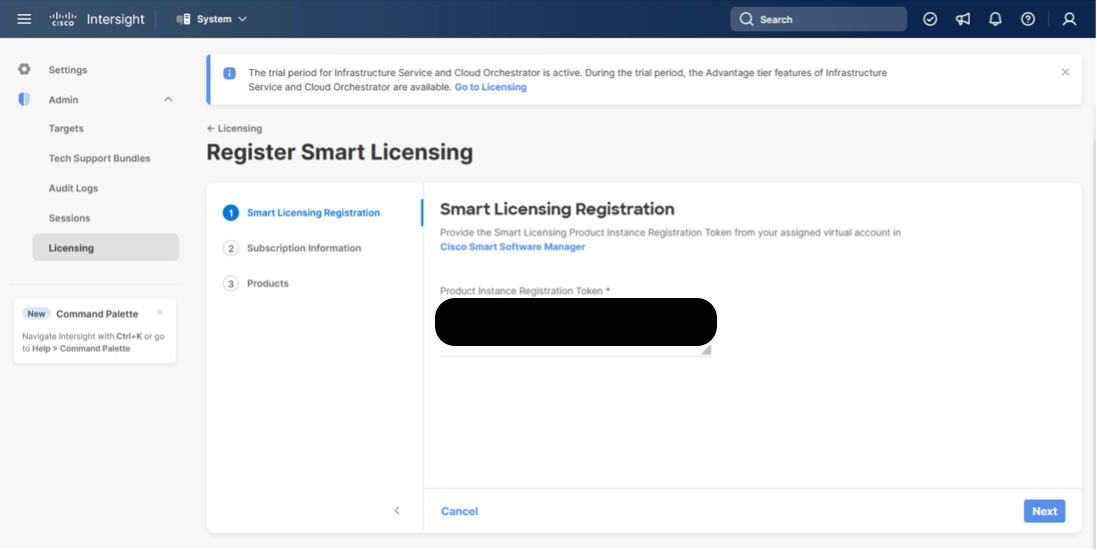
Step 7. Provide the copied token from the Cisco Smart Licensing Portal. Click Next.
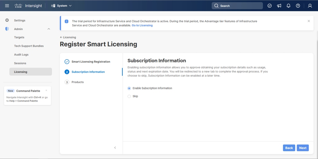
Step 8. Select Enable or Skip subscription information and click Next.
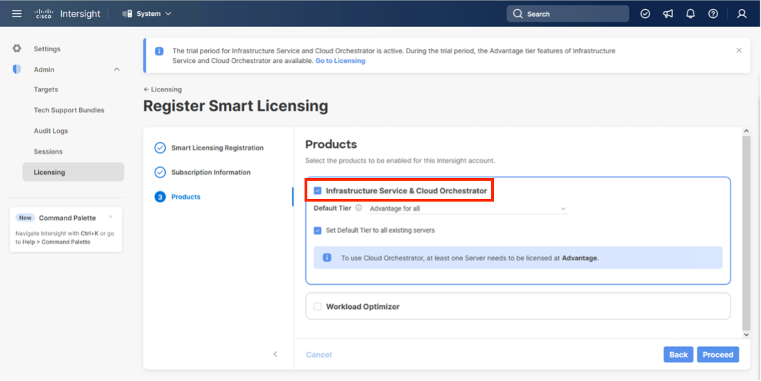
Step 9. Select the Infrastructure Service & Cloud Orchestrator option, adjust the default tier for licensing if needed, and if this should be used for existing servers, click Proceed. Click Confirm when asked to verify options.
On successfully syncing the Smart Licensing, the following page displays:
On successfully creating the Intersight account with trial licensing, the following page displays:
Procedure 3. Configure Cisco Intersight Resource Group
In this procedure, a Cisco Intersight resource group is created where resources such as targets will be logically grouped. In this deployment, a single resource group is created to host all the resources, but you can choose to create multiple resource groups for granular control of the resources.
Step 1. Log in to Cisco Intersight.
Step 2. At the top, select System. On the left, click Settings (the gear icon).
Step 3. Click Resource Groups in the middle panel.
Step 4. Click + Create Resource Group in the top-right corner.
Step 5. Provide a name for the Resource Group (for example, AA24-rg).
Step 6. Click Create.
Procedure 4. Configure Cisco Intersight Organization
This procedure creates an Intersight organization where all Cisco Intersight managed mode configurations including policies are defined. To create a new organization, follow these steps:
Step 1. Log in to the Cisco Intersight portal.
Step 2. At the top, select System. On the left, click Settings (the gear icon).
Step 3. Click Organizations in the middle panel.
Step 4. Click + Create Organization in the top-right corner.
Step 5. Provide a name for the organization (for example, AA24) and click Next.
Step 6. Select the Resource Group created in the last step (for example, AA24-rg) and click Next.
Step 7. Review the Summary and click Create.
The UCS domain contained within the Fabric Interconnects will be added directly to the account as targets. The other infrastructure components will be onboarded as targets through the Intersight Assist Appliance after it has been deployed, explained later in section Management Configuration.
Procedure 1. Configure the Cisco UCS X-Direct Fabric Interconnects
The Cisco UCS X-Direct fabric interconnects support UCSM mode but will default to IMM mode with the currently shipping code. This guide will cover IMM deployment and configuration, UCSM configuration can be implemented following previous CVD examples, or referencing the current Cisco documentation covering UCSM configuration.
Note: Configuring X-Direct is started through the serial console, this connection will be 115200 baud instead of 9600 baud used by many other Cisco devices.
To start the configuration, follow these steps:
Step 1. Configure Fabric Interconnect A (FI-A) by connecting to the FI-A console. On the Basic System Configuration Dialog screen, set the management mode to Intersight:
Cisco UCS Fabric Interconnect A
Enter the configuration method. (console/gui) ? console
The Fabric interconnect will be configured in the intersight managed mode. Choose (y/n) to proceed: y
Enforce strong password? (y/n) [y]: Enter
Enter the password for "admin": <password>
Confirm the password for "admin": <password>
Enter the switch fabric (A/B) []: A
Enter the system name: <ucs-cluster-name>
Physical Switch Mgmt0 IP address : <ucsa-mgmt-ip>
Physical Switch Mgmt0 IPv4 netmask : <ucs-mgmt-mask>
IPv4 address of the default gateway : <ucs-mgmt-gateway>
DNS IP address : <dns-server-1-ip>
Configure the default domain name? (yes/no) [n]: n <optional>
Following configurations will be applied:
Management Mode=intersight
Switch Fabric=A
System Name=<ucs-cluster-name>
Enforced Strong Password=yes
Physical Switch Mgmt0 IP Address=<ucsa-mgmt-ip>
Physical Switch Mgmt0 IP Netmask=<ucs-mgmt-mask>
Default Gateway=<ucs-mgmt-gateway>
DNS Server=<dns-server-1-ip>
Apply and save the configuration (select 'no' if you want to re-enter)? (yes/no): yes
Step 2. After applying the settings, make sure you can ping the fabric interconnect management IP address. When Fabric Interconnect A is correctly set up and is available, Fabric Interconnect B will automatically discover Fabric Interconnect A during its setup process as shown in the next step.
Step 3. Configure Fabric Interconnect B (FI-B). For the configuration method, choose console. Fabric Interconnect B will detect the presence of Fabric Interconnect A and will prompt you to enter the admin password for Fabric Interconnect A. Provide the management IP address for Fabric Interconnect B and apply the configuration:
Cisco UCS Fabric Interconnect B
Enter the configuration method. (console/gui) ? console
Installer has detected the presence of a peer Fabric interconnect. This Fabric interconnect will be added to the cluster. Continue (y/n) ? y
Enter the admin password of the peer Fabric interconnect: <password>
Connecting to peer Fabric interconnect... done
Retrieving config from peer Fabric interconnect... done
Peer Fabric interconnect management mode : intersight
Peer Fabric interconnect Mgmt0 IPv4 Address: <ucsa-mgmt-ip>
Peer Fabric interconnect Mgmt0 IPv4 Netmask: <ucs-mgmt-mask>
Peer FI is IPv4 Cluster enabled. Please Provide Local Fabric Interconnect Mgmt0 IPv4 Address
Physical Switch Mgmt0 IP address : <ucsb-mgmt-ip>
Apply and save the configuration (select 'no' if you want to re-enter)? (yes/no): yes
Applying configuration. Please wait.
Procedure 2. Claim Cisco UCS Fabric Interconnects in Cisco Intersight
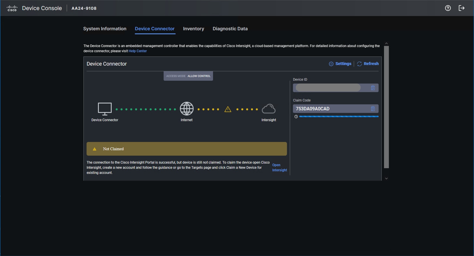
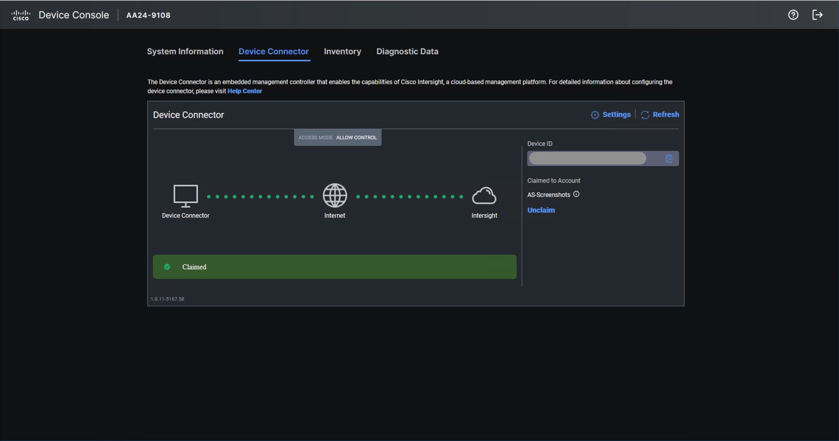
Note: With the initial Basic System Configuration Dialog previously completed for the fabric interconnects, log into the Fabric Interconnect A Device Console using a web browser to capture the Cisco Intersight connectivity information.
Step 1. Use the management IP address of Fabric Interconnect A to access the device from a web browser and the previously configured admin password to log into the device.
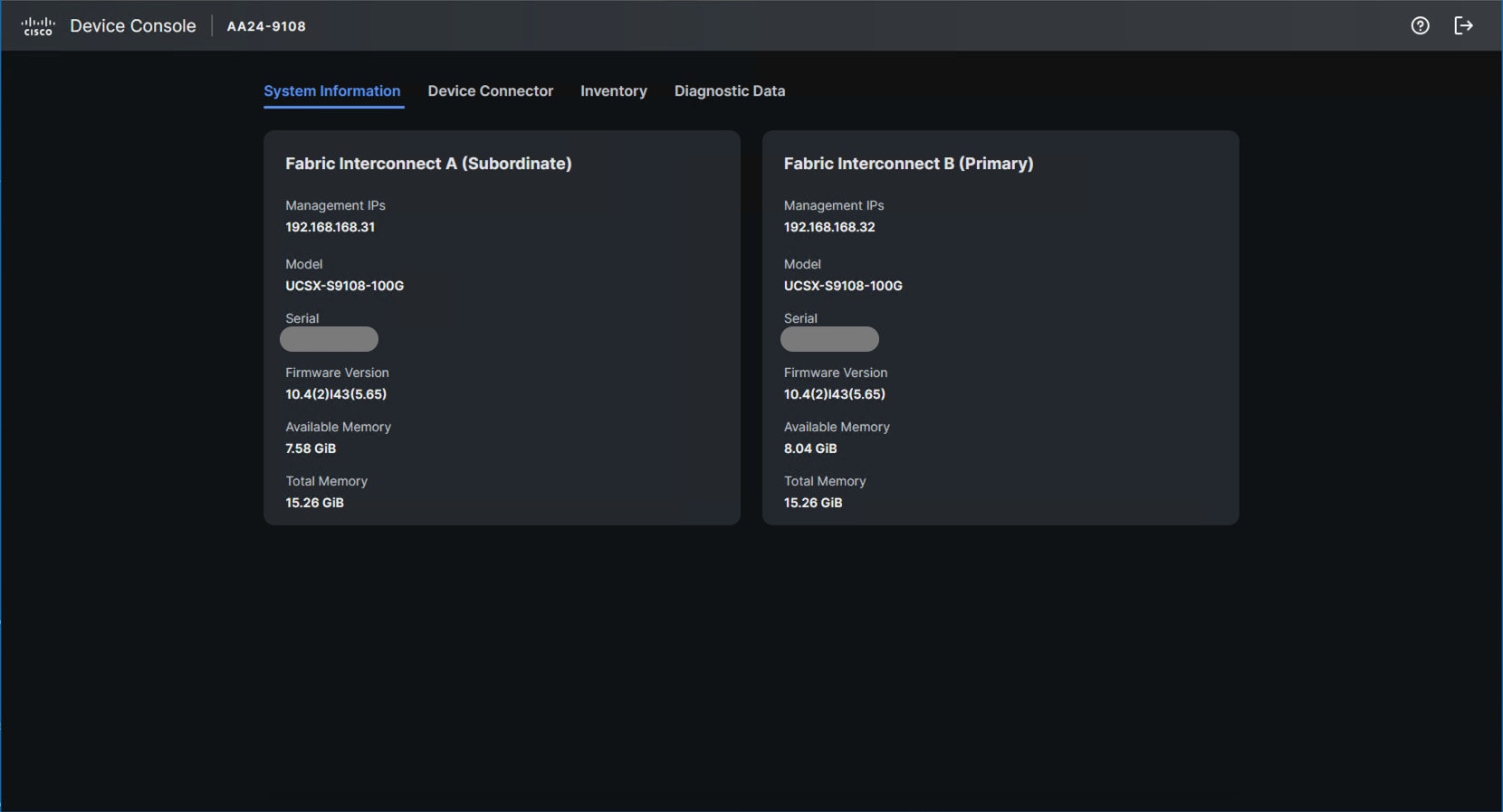
Step 2. Under DEVICE CONNECTOR, the current device status will show Not claimed. Note or copy the Device ID and Claim Code information for claiming the device in Cisco Intersight.
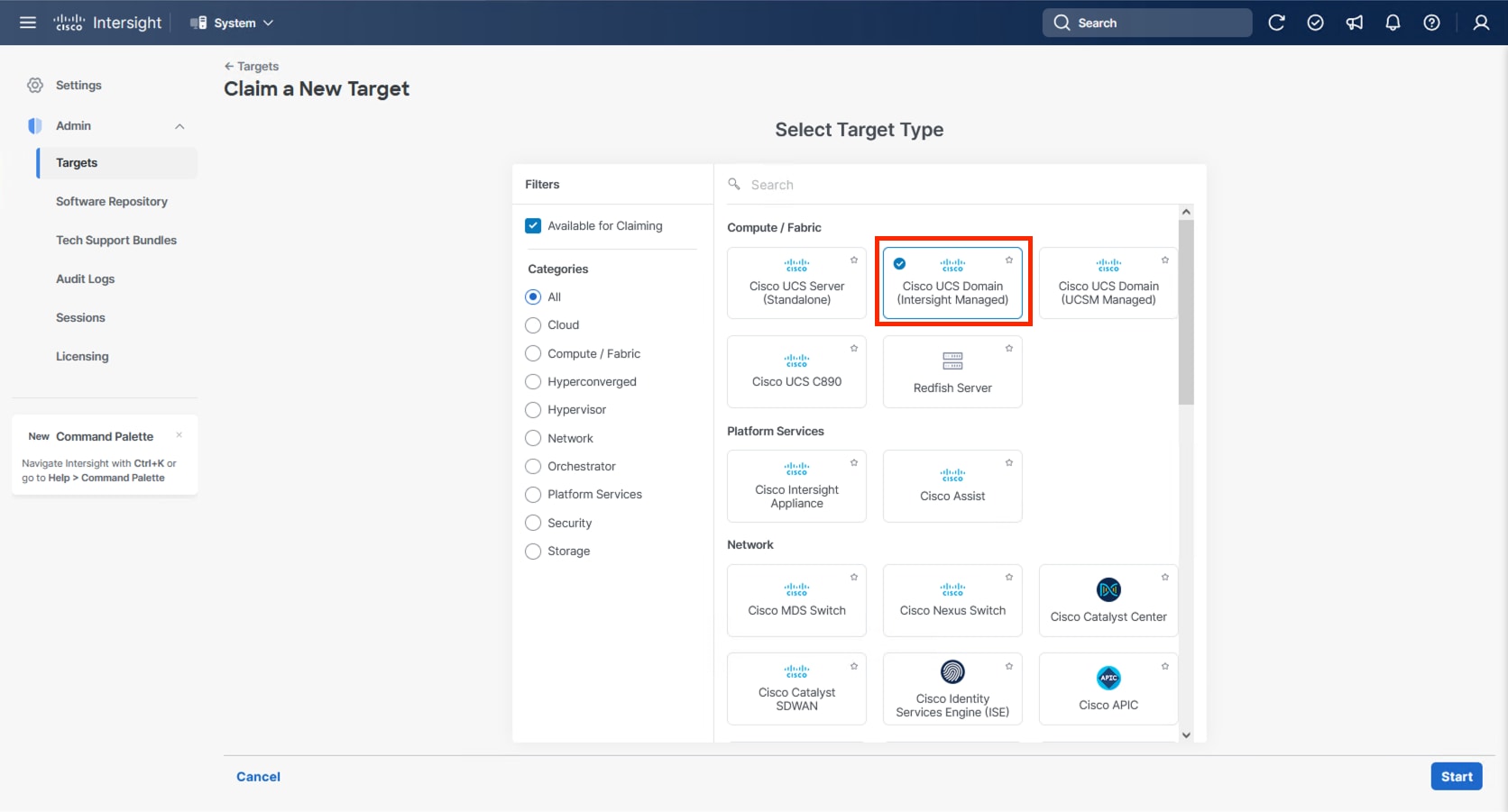
Step 3. Log in to Cisco Intersight.
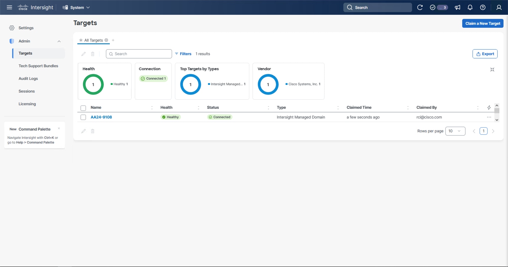
Step 4. At the top, select System. On the left, click Administration > Targets.
Step 5. Click Claim a New Target.
Step 6. Select Cisco UCS Domain (Intersight Managed) and click Start.
Step 7. Copy and paste the Device ID and Claim Code from the Cisco UCS FI in Step 2 to Intersight.
Step 8. Select the previously created resource group and click Claim.
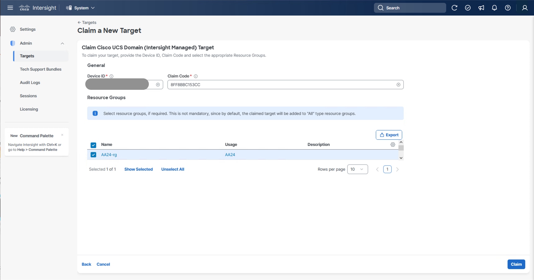
With a successful device claim, Cisco UCS FI appears as a target in Cisco Intersight:
Step 9. Log into the web GUI of the Cisco UCS fabric interconnect and click the browser Refresh button.
The fabric interconnect status is now set to Claimed:
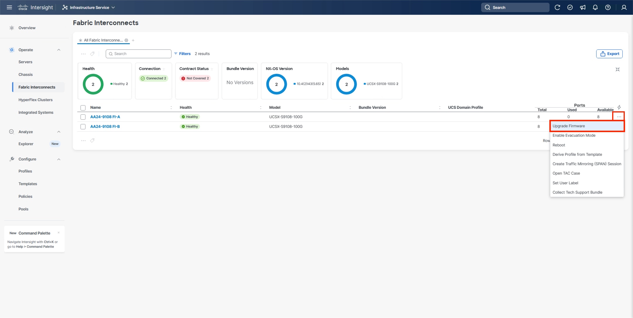
Procedure 3. Upgrade Fabric Interconnect Firmware using Cisco Intersight
Step 1. Log into the Cisco Intersight portal.
Step 2. At the top, from the drop-down list select Infrastructure Service and then select Fabric Interconnects under Operate on the left.
Step 3. Click the ellipses “…” at the end of the row for either of the Fabric Interconnects and select Upgrade Firmware.
Step 4. Click Start.
Step 5. Verify the Fabric Interconnect information and click Next.
Step 6. Enable Advanced Mode using the toggle switch and uncheck Fabric Interconnect Traffic Evacuation.
Step 7. Select 4.3(5) or other currently appropriate release from the list and click Next.
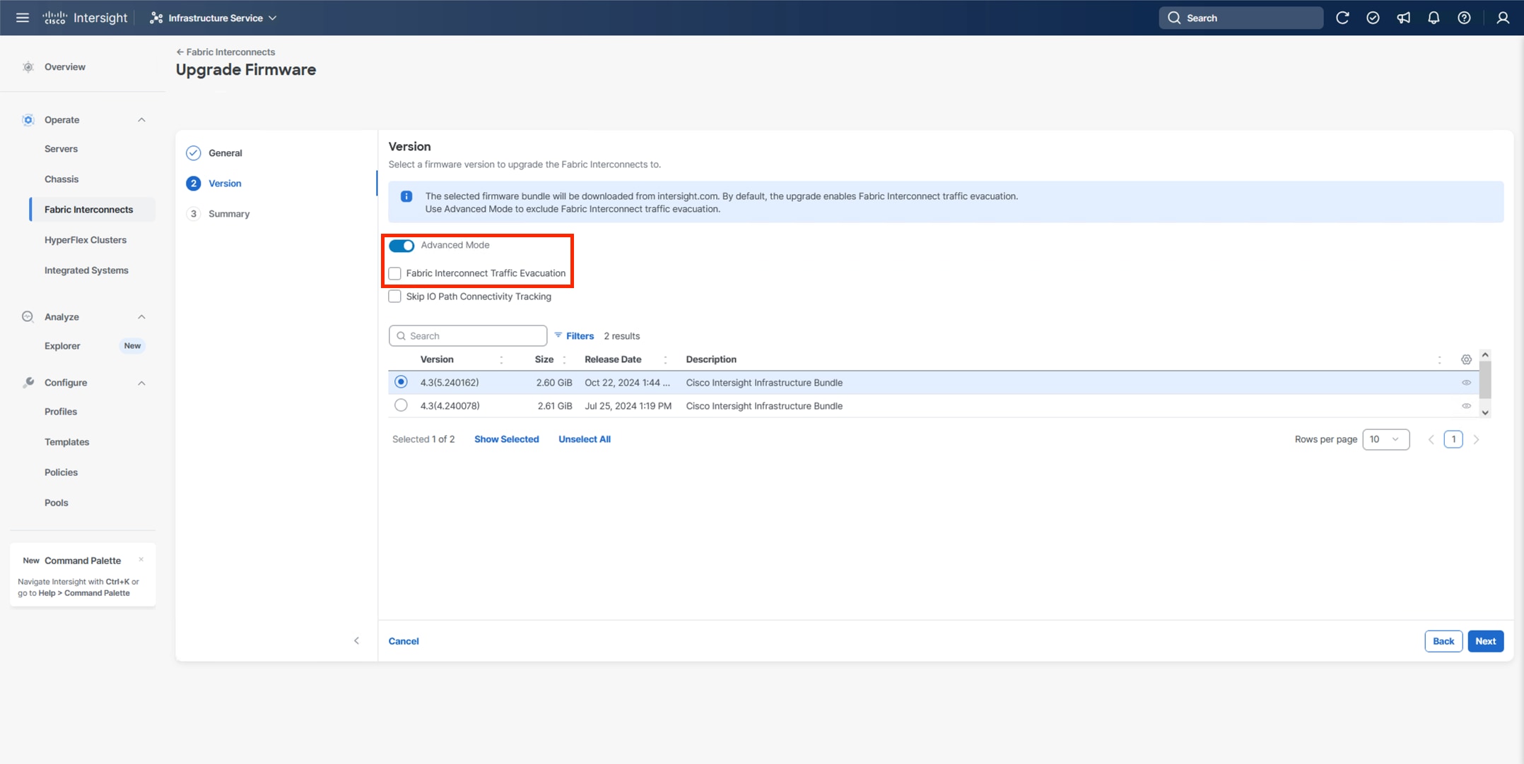
Note: 4.3(5) is the minimum required release version for supporting X215c M8 Compute Nodes.
Step 8. Verify the information and click Upgrade to start the upgrade process.
Step 9. Watch the Request panel of the main Intersight screen since the system will prompt for user permission before upgrading each FI. Click the Circle with Arrow and follow the prompts on the screen to grant permission.
Step 10. Wait for both the FIs to successfully upgrade.
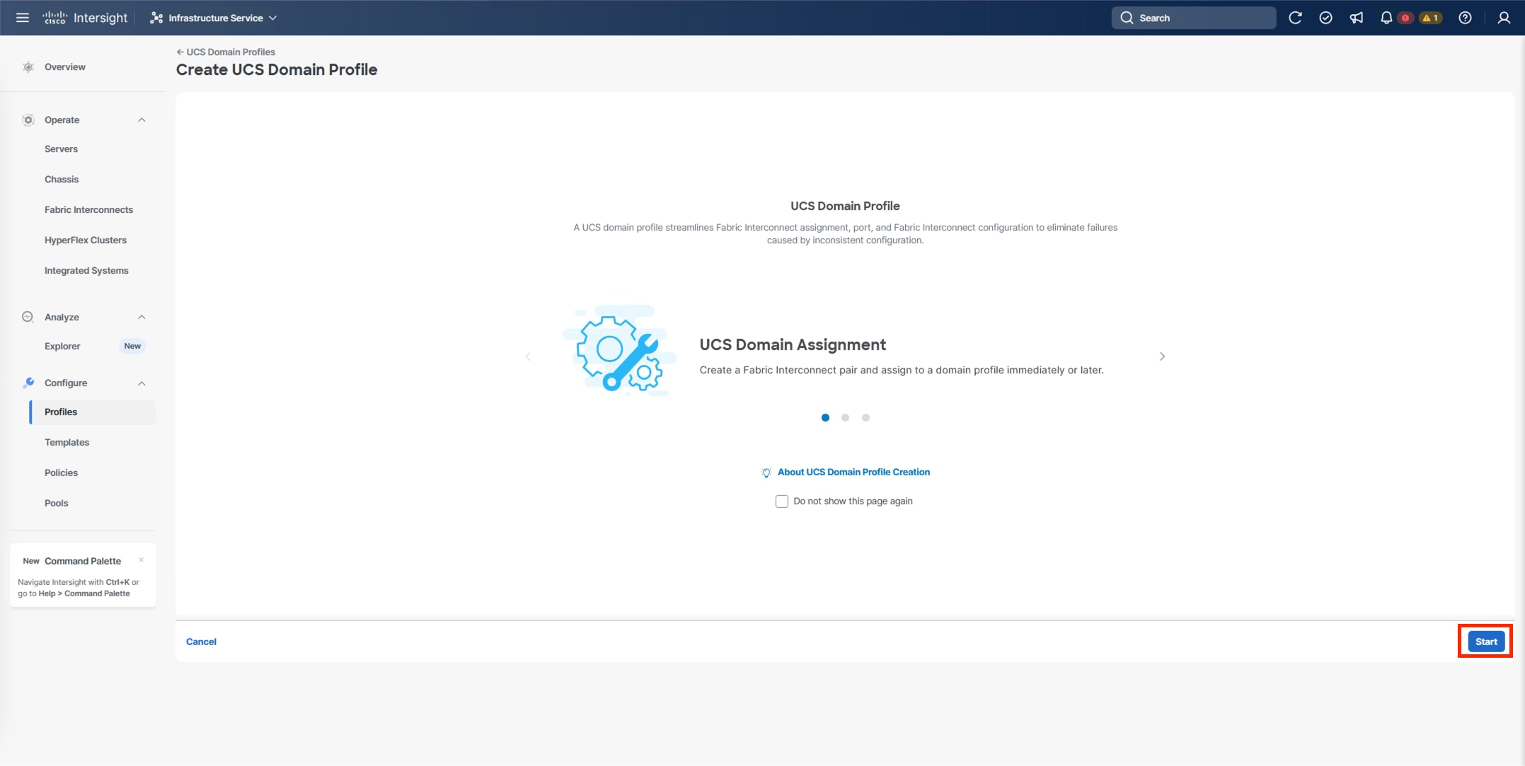
A Cisco UCS domain profile configures a fabric interconnect pair through reusable policies, allows configuration of the ports and port channels, and configures the VLANs and VSANs in the network. It defines the characteristics of and configured ports on fabric interconnects. The domain-related policies can be attached to the profile either at the time of creation or later. One Cisco UCS domain profile can be assigned to one fabric interconnect domain.
Procedure 1. Configure a Cisco UCS Domain Profile
Step 1. Log into the Cisco Intersight portal.
Step 2. At the top, from the drop-down list, select Infrastructure Service and under Configure, select Profiles.
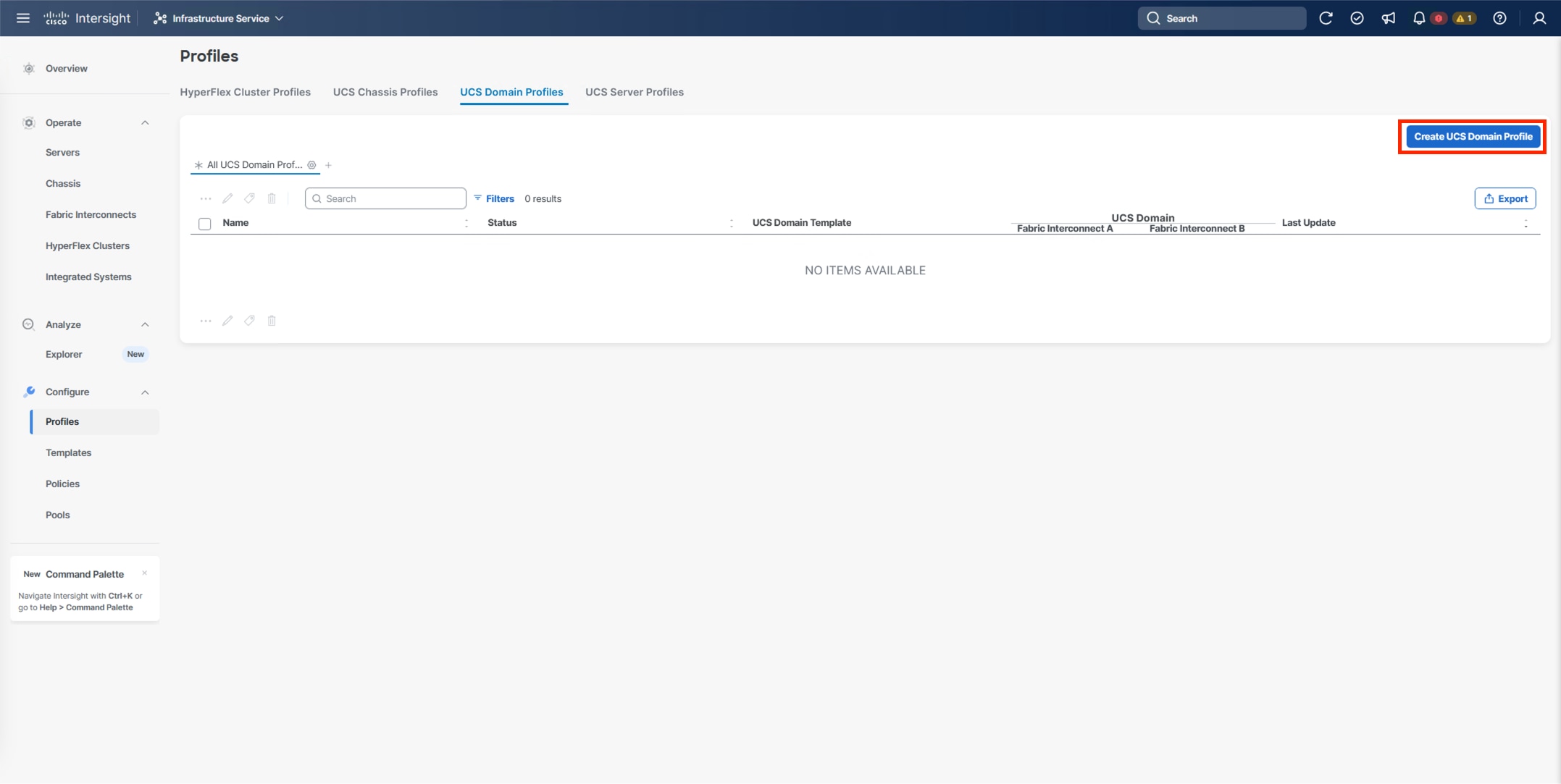
Step 3. In the main window, select UCS Domain Profiles and click Create UCS Domain Profile.
Step 4. From the Create UCS Domain Profile screen, click Start.
Procedure 2. UCS Domain Profile General Configuration
Step 1. Select the organization from the drop-down list (for example, AA24).
Step 2. Provide a name for the domain profile (for example, AA24-X-Direct-Domain-Profile).
Step 3. Provide an optional Description.
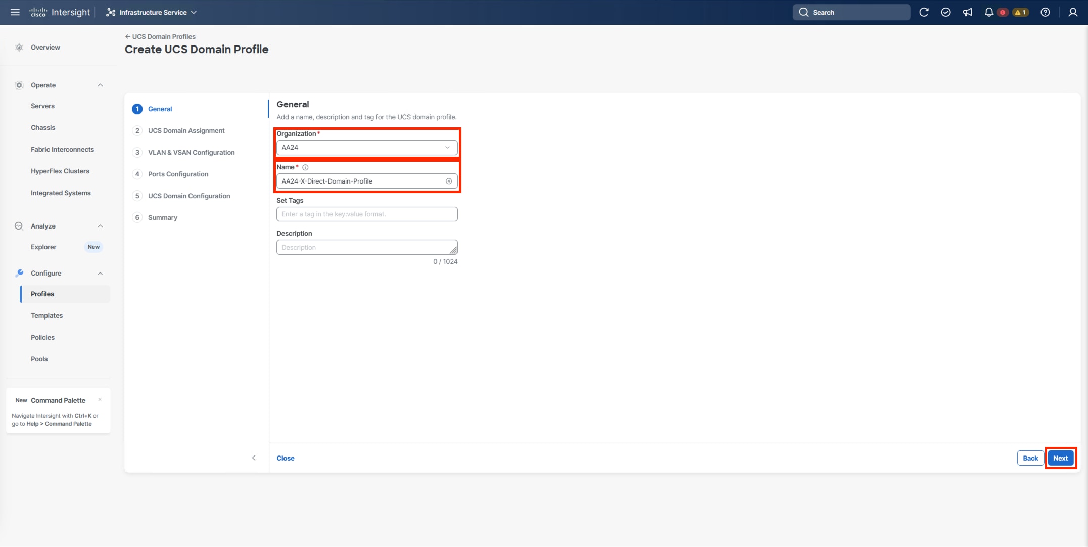
Step 4. Click Next.
Procedure 3. UCS Domain Assignment
Step 1. Assign the Cisco UCS domain to this new domain profile by clicking Assign Now and select the previously added Cisco UCS domain (for example, AA24-9108).
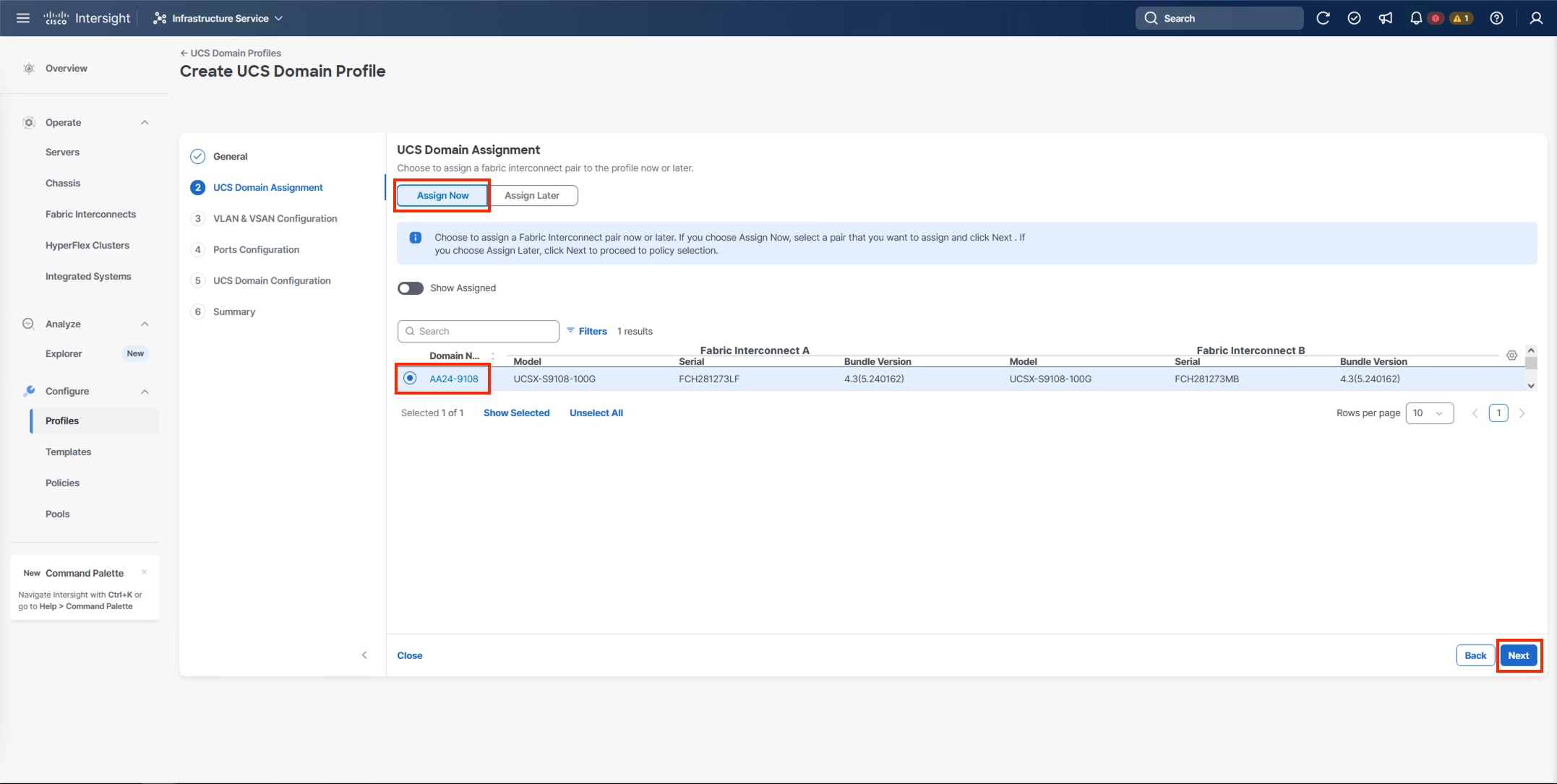
Step 2. Click Next.
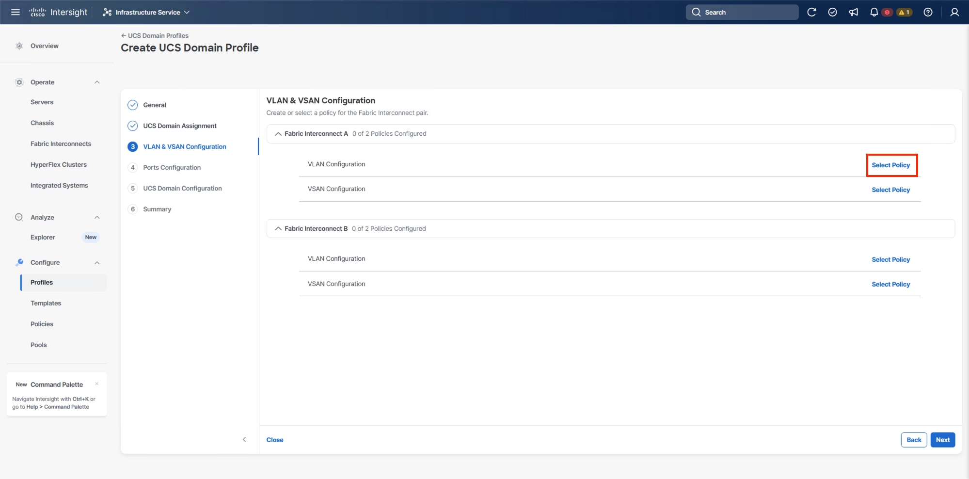
Procedure 4. VLAN and VSAN Configuration
In this procedure, a single VLAN policy is created for both fabric interconnects and two individual VSAN policies are created because the VSAN IDs are unique for each fabric interconnect that are applied to the UCS Domain.
VLAN Configuration
Step 1. Click Select Policy next to VLAN Configuration under Fabric Interconnect A.
Step 2. In the pane on the right, click Create New.
Step 3. Verify the correct organization is selected from the drop-down list (for example, AA24) and provide a name for the policy (for example, AA24-VLAN).
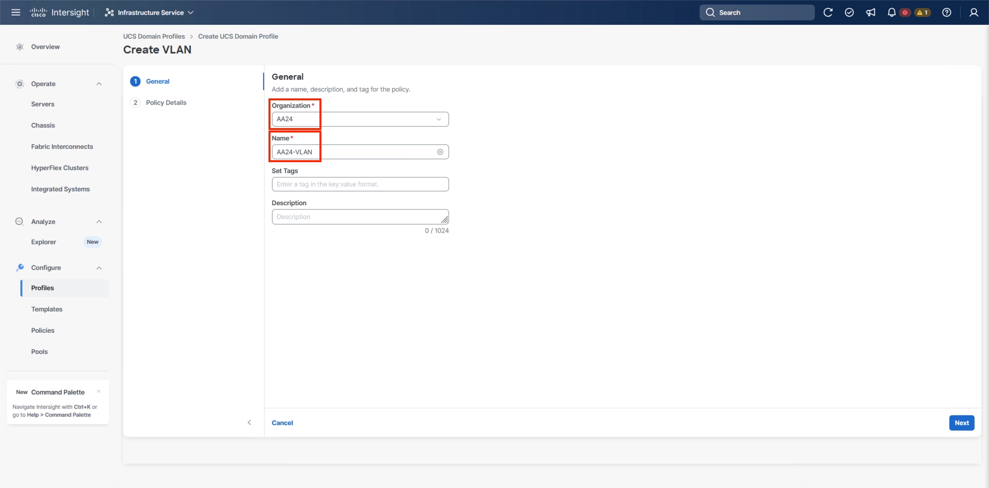
Step 4. Click Next.
Step 5. Click Add VLANs.
Step 6. Provide a name and VLAN ID for the native VLAN.
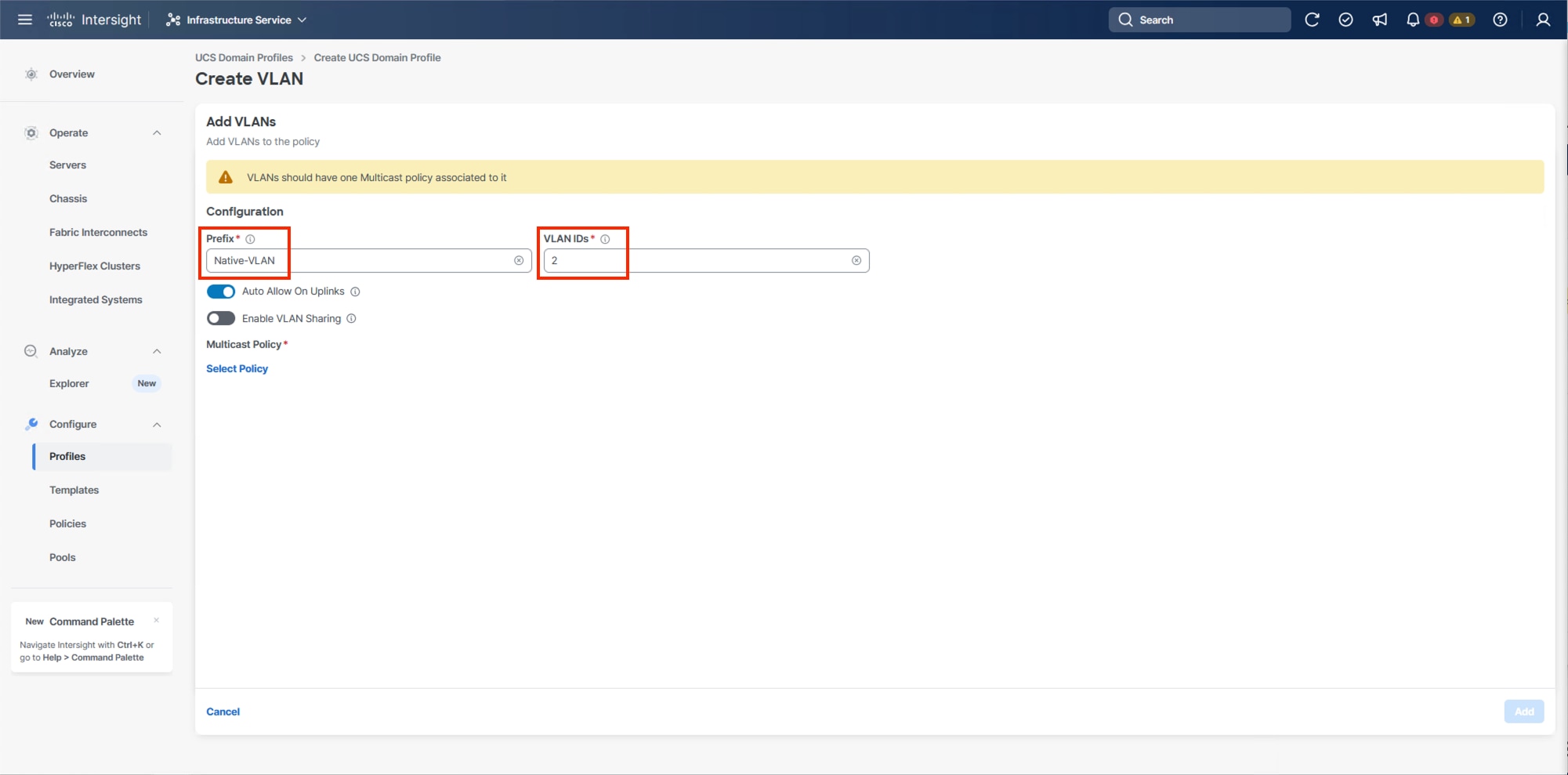
Step 7. Make sure Auto Allow On Uplinks is enabled.
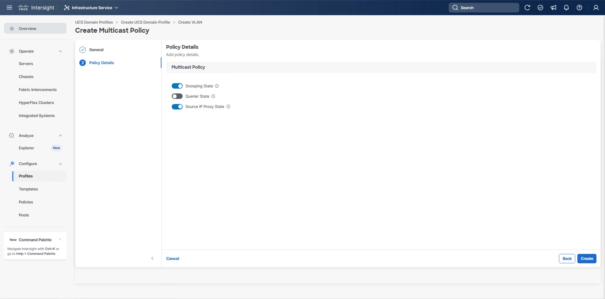
Step 8. To create the required Multicast policy, click Select Policy under Multicast Policy*.
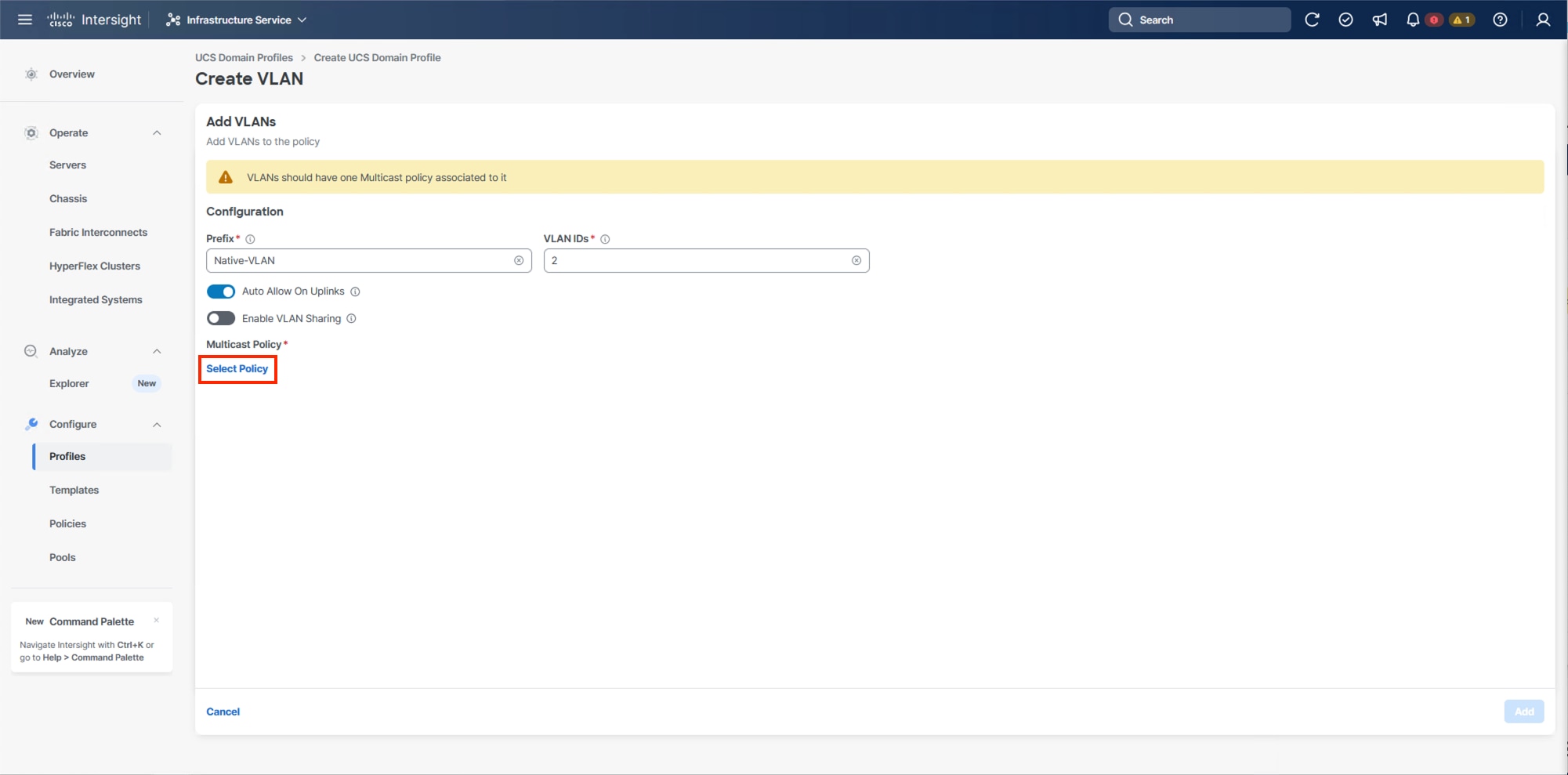
Step 9. In the window on the right, click Create New to create a new Multicast Policy.
Step 10. Provide a Name for the Multicast Policy (for example, AA24-MCAST).
Step 11. Provide optional Description and click Next.
Step 12. Leave the default settings selected and click Create.
Step 13. Click Add to add the VLAN.
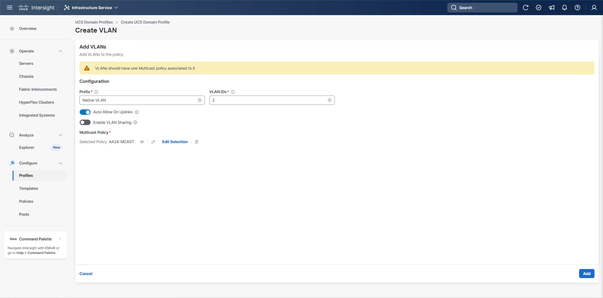
Step 14. Add the remaining VLANs listed in Table 2. Click Add VLANs and enter the VLANs one by one. Reuse the previously created multicast policy for all the VLANs.
Step 15. Select Set Native VLAN ID and enter the VLAN number (for example, 2) under VLAN ID.
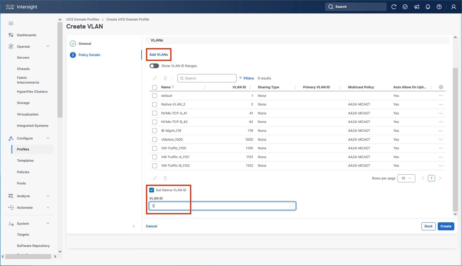
Step 16. Click Create to finish creating the VLAN policy and associated VLANs.
Step 17. Click Select Policy next to VLAN Configuration for Fabric Interconnect B and select the same VLAN policy.
VSAN Configuration
Note: The VSAN Configuration will not be used in this X-Direct solution. VSP One based design using IP storage, FC and FC-NVMe based implementations should reference the previous VSI CVD Deployment Guide.
Step 1. Confirm the VLAN Policy is applied to both fabric interconnects.
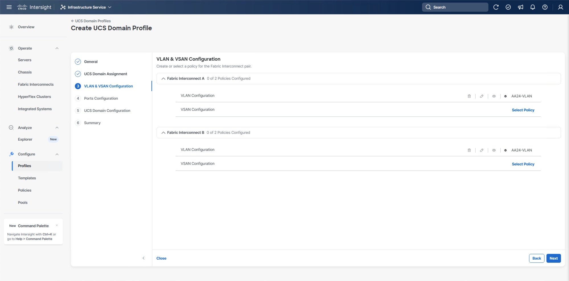
Step 2. Click Next.
Procedure 5. Ports Configuration
This procedure creates the Ports Configuration policies for Fabric Interconnect A and uses the same Port Configuration policy for Fabric Interconnect B. If there are variances in port configuration and between the two fabric interconnects, separate policies can be created.
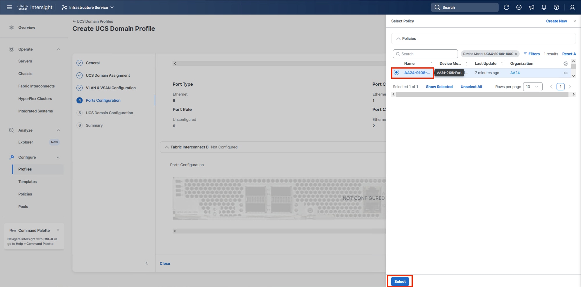
Step 1. Click Select Policy for Fabric Interconnect A.
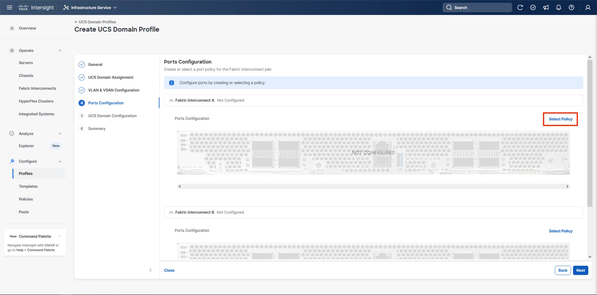
Step 2. Click Create New in the pane on the right to define a new port configuration policy.
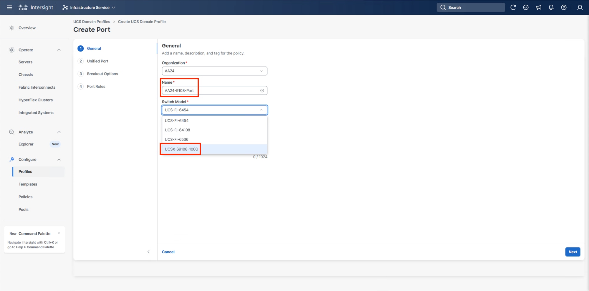
Step 3. Verify that the correct organization is selected from the drop-down list (for example, AA24) and provide a name for the policy (for example, AA24-9108-Port). Select the UCSX-S9108-100G Switch Model.
Step 4. Click Next.
Step 5. Ignore the Unified Port configuration. Click Next.
Step 6. There are no breakout ports configured in the validated architecture, ignore the Breakout Options unless making adjustments required by your placement. Click Next.
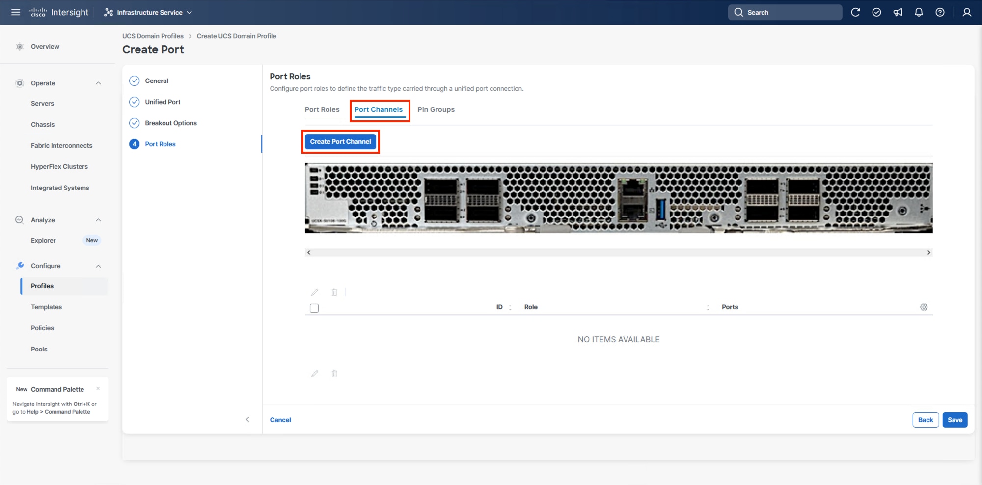
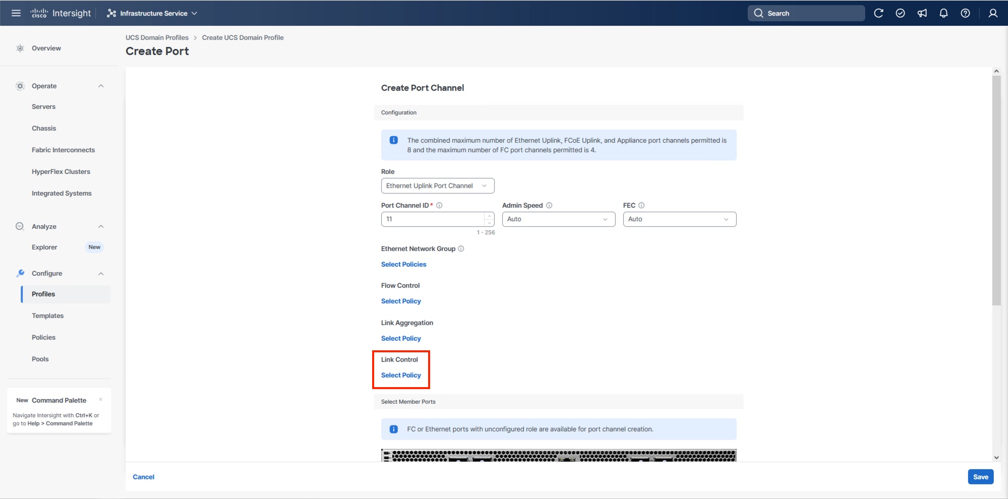
Step 7. In Port Roles, click the Port Channels tab in the center and click Create Port Channel.
Step 8. To create the network uplinks to the Nexus 93600CD-GX switches, leave the Role as Ethernet Uplink Port selected.
Step 9. Specify a Port Channel ID (example 11). Specify an Admin Speed if the upstream ports require it, otherwise leave it as Auto, and leave Forward Error Correction (FEC) as Auto.
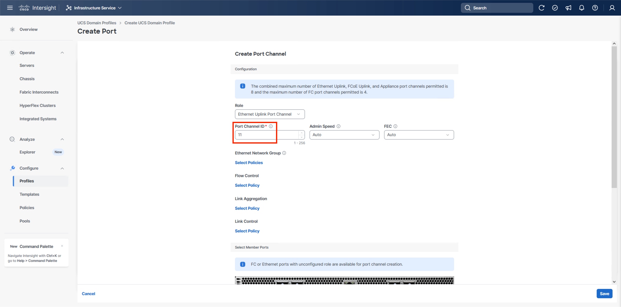
Note: Ethernet Network Group, Flow Control, and Link Aggregation policies for defining a disjoint Layer-2 domain or fine tune port-channel parameters can be configured here, but these policies were not used in this deployment and system default values were utilized.
Step 10. Scroll down to Link Control and if Select Member Ports is not visible within the Create Port Channel dialogue, click Select Policy under Link Control and then select Create New.
Step 11. Provide a name for the policy (example, AA24-UDLD-Link-Control) and click Next.
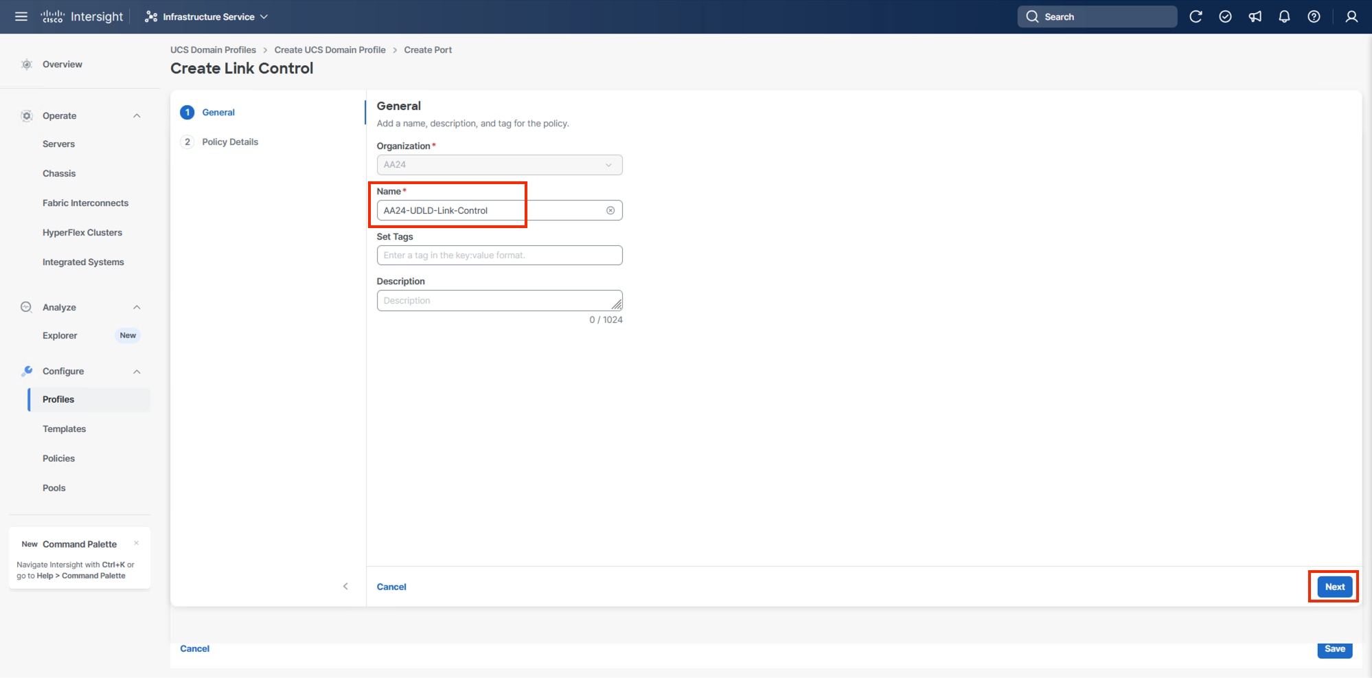
Step 12. Leave the default values selected and click Create.
Step 13. Scroll down to select the ports connected to the upstream Nexus switches (example, port 7 and 8).
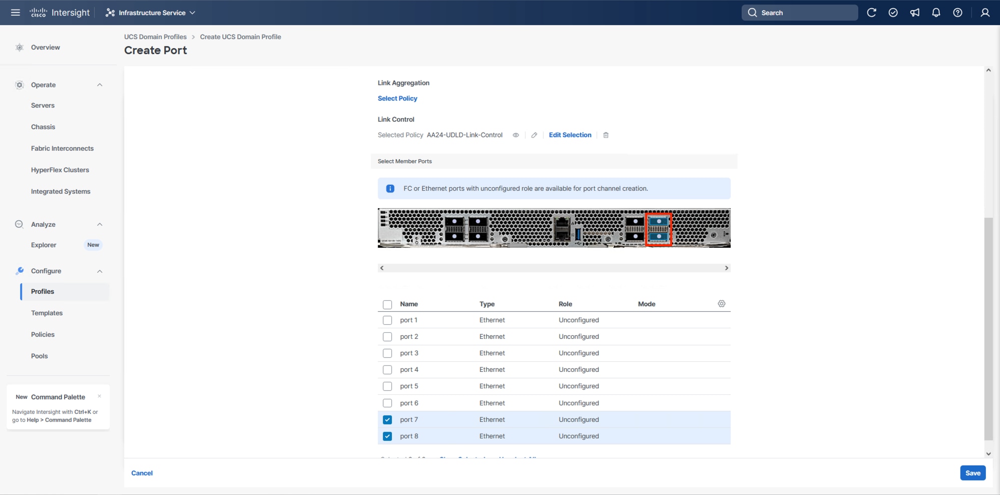
Step 14. Click Save.
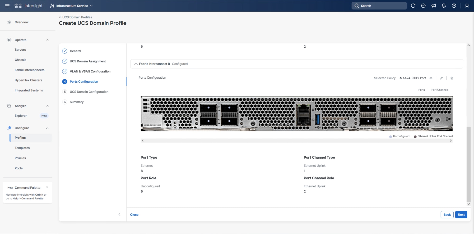
Step 15. Scroll down to Fabric Interconnect B and click Select Policy.
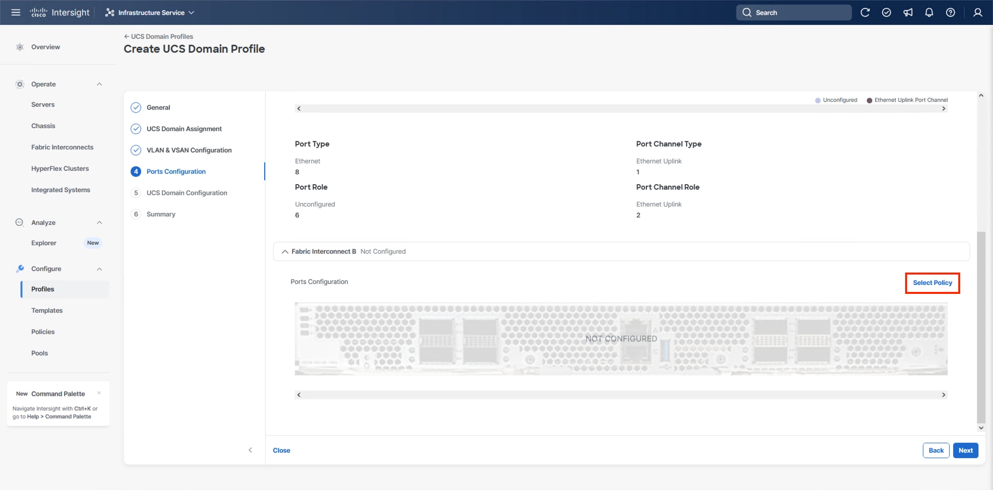
Step 16. On the right-side panel, select the previously created Port Policy and click Select.
Note: Without a need for FC port-channels needed in this design, the same Port Policy can be used on both fabrics.
Step 17. Click Save.
Step 18. Click Next.
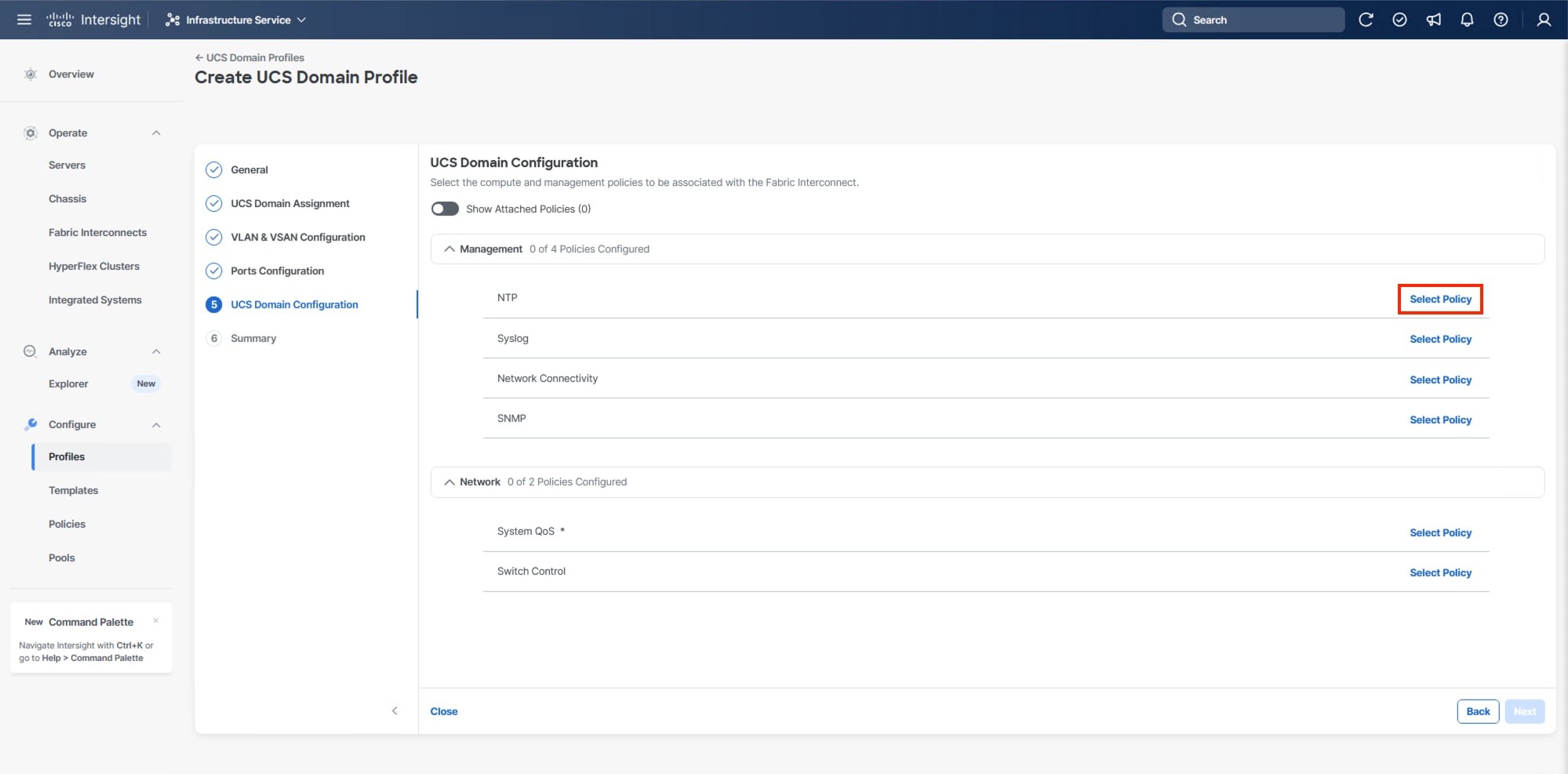
Configure UCS Domain
Under UCS domain configuration, additional policies can be configured to set up NTP, Syslog, DNS settings, SNMP, QoS and the UCS operating mode (end host or switch mode). For this deployment, four policies (NTP, Network Connectivity, SNMP, and System QoS) will be configured.
Procedure 1. Configure NTP Policy
Step 1. Click Select Policy next to NTP and in the pane on the right, click Create New.
Step 2. Verify the correct organization is selected from the drop-down list (for example, AA24) and provide a name for the policy (for example, AA24-NTP).
Step 3. Click Next.
Step 4. Enable NTP should be selected, provide the first NTP server IP address, and select the time zone from the drop-down list.
Step 5. (Optional) Add a second NTP server by clicking + next to the first NTP server IP address.
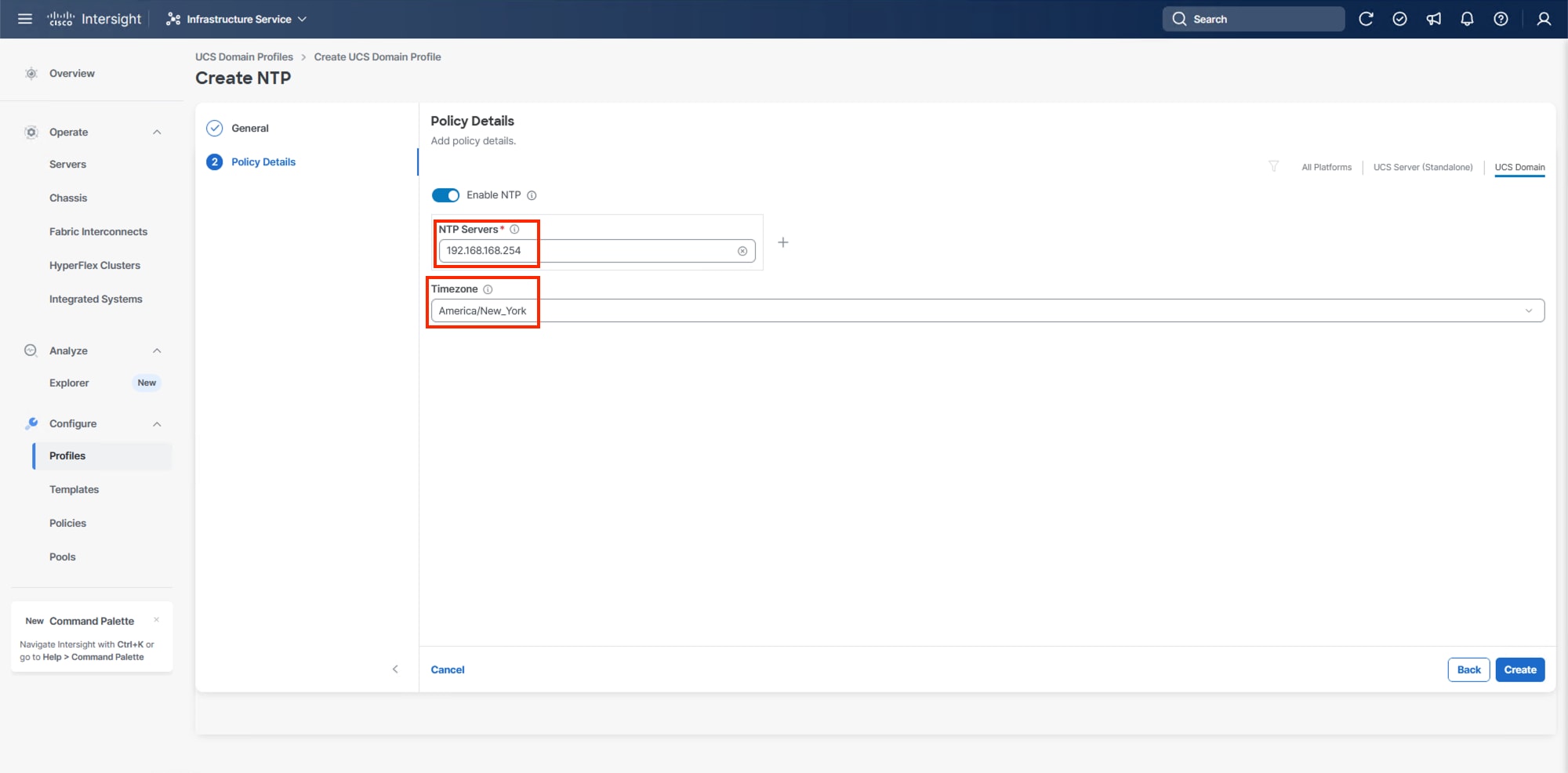
Step 6. Click Create.
Procedure 2. Configure Network Connectivity Policy
Step 1. Click Select Policy next to Network Connectivity and then, in the pane on the right, click Create New.
Step 2. Verify that the correct organization is selected from the drop-down list (for example, AA24) and provide a name for the policy (for example, AA24-NetConn).
Step 3. Click Next.
Step 4. Provide the appropriate DNS server IP addresses for the Cisco UCS domain.
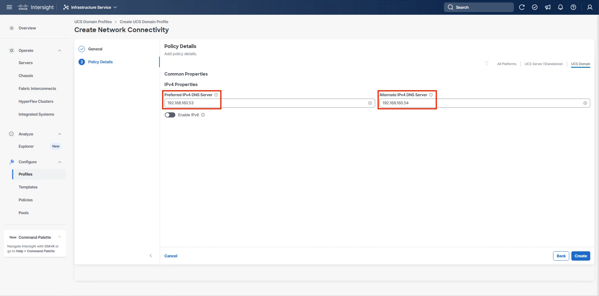
Step 5. Click Create.
Procedure 3. Configure SNMP Policy (Optional)
Step 1. Click Select Policy next to SNMP and then, in the pane on the right, click Create New.
Step 2. Verify that the correct organization is selected from the drop-down list (for example, AA24) and provide a name for the policy (for example, AA24-SNMP).
Step 3. Click Next.
Step 4. Provide a System Contact email address, a System Location, and optional Community Strings.
Step 5. Under SNMP Users, click Add SNMP User.
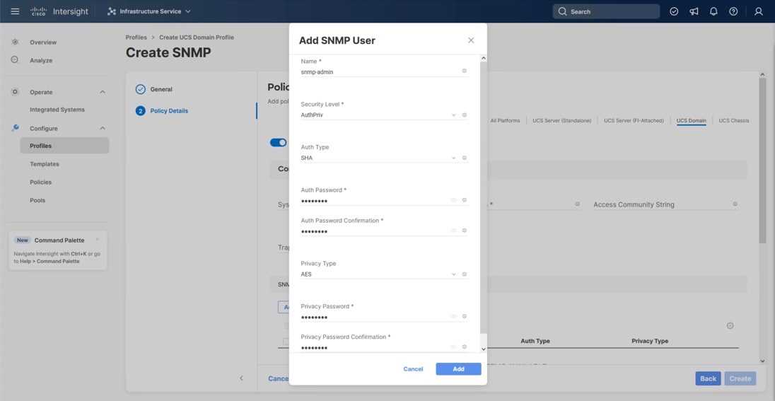
Step 6. Optionally, add an SNMP Trap Destination (for example, the NDFC IP Address). If the SNMP Trap Destination is V2, you must add a Trap Community String.
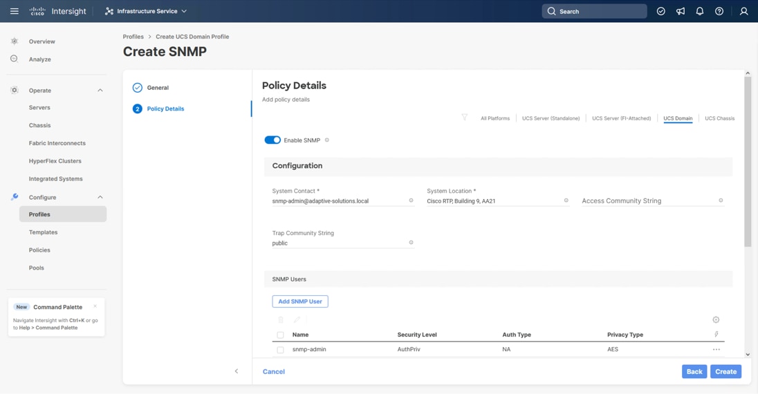
Step 7. Click Create.
Procedure 4. Configure System QoS Policy
The System QoS policy will be adjusted to expand the capacity of the Ethernet uplinks to support jumbo frames. All Ethernet traffic is set within a common class of Best Effort in this design, which will have the MTU adjusted. Different strategies can be implemented for QoS giving weighted priorities, but any such effort would need to take care to match settings implemented upstream of the fabric interconnects.
Step 1. Click Select Policy next to System QoS* and in the pane on the right, click Create New.
Step 2. Verify that the correct organization is selected from the drop-down list (for example, AA24) and provide a name for the policy (for example, AA24-QoS).
Step 3. Click Next.
Step 4. Change the MTU for Best Effort class to 9216.
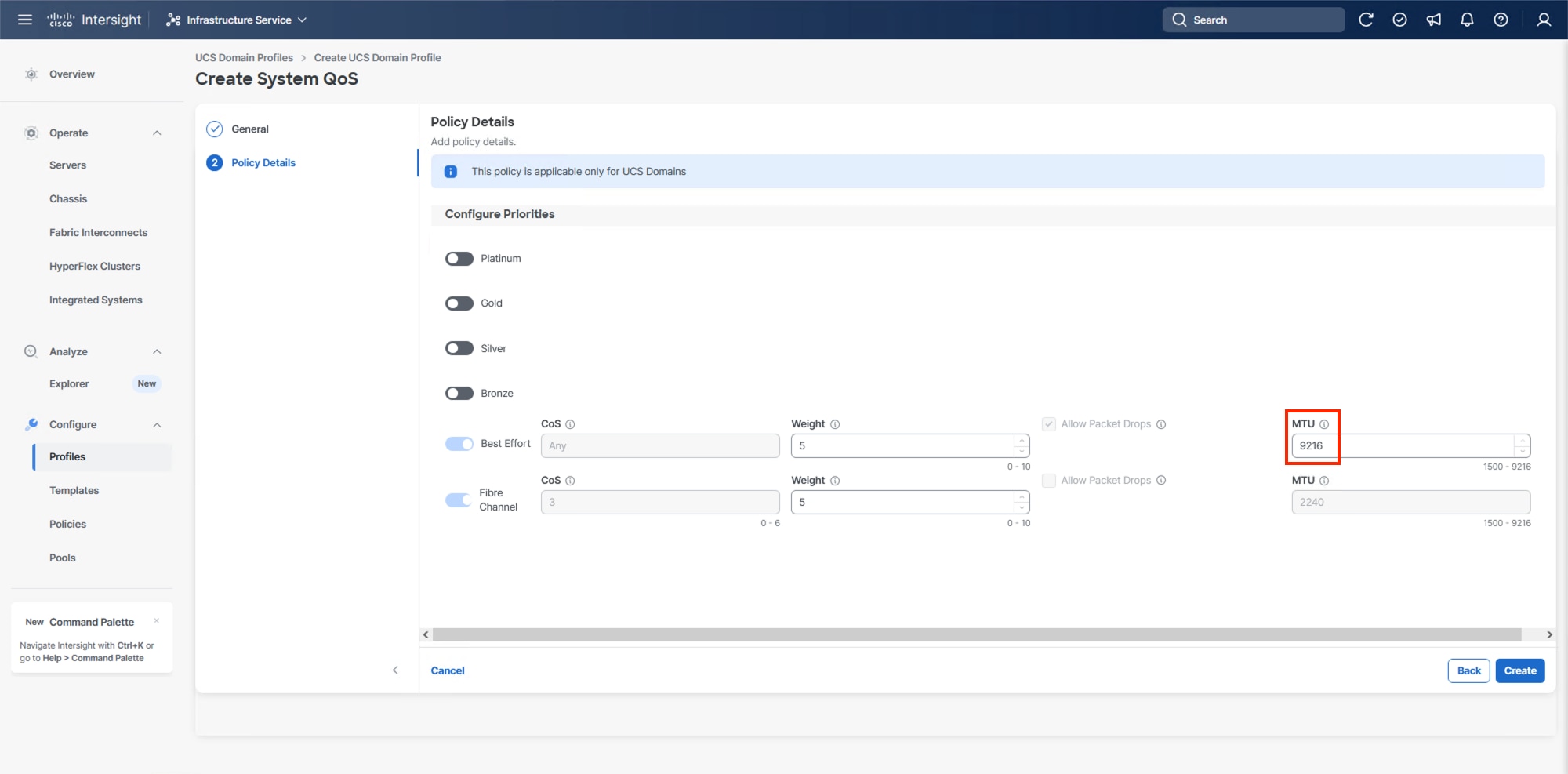
Step 5. Click Create.
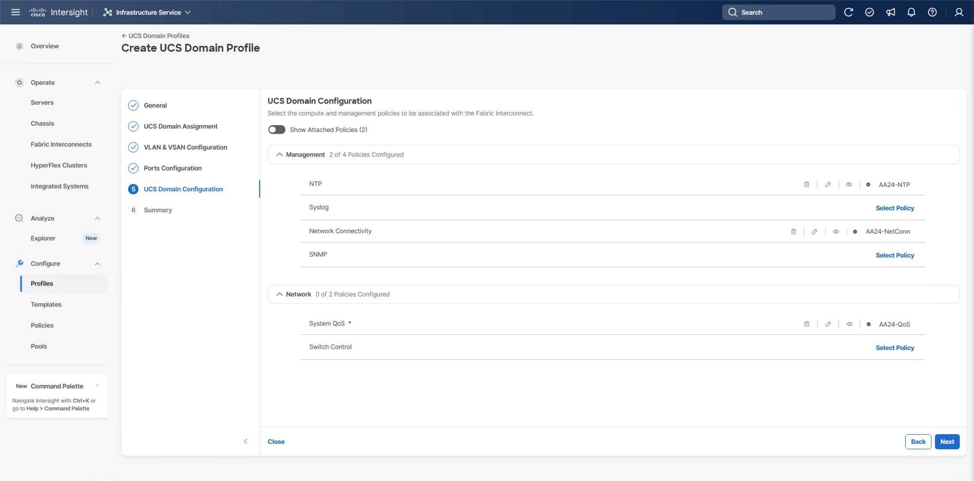
Step 6. Click Next.
Procedure 5. Deploy the UCS Domain Profile
Step 1. Verify all settings, including the fabric interconnect settings, by expanding the settings and making sure that the configuration is correct.
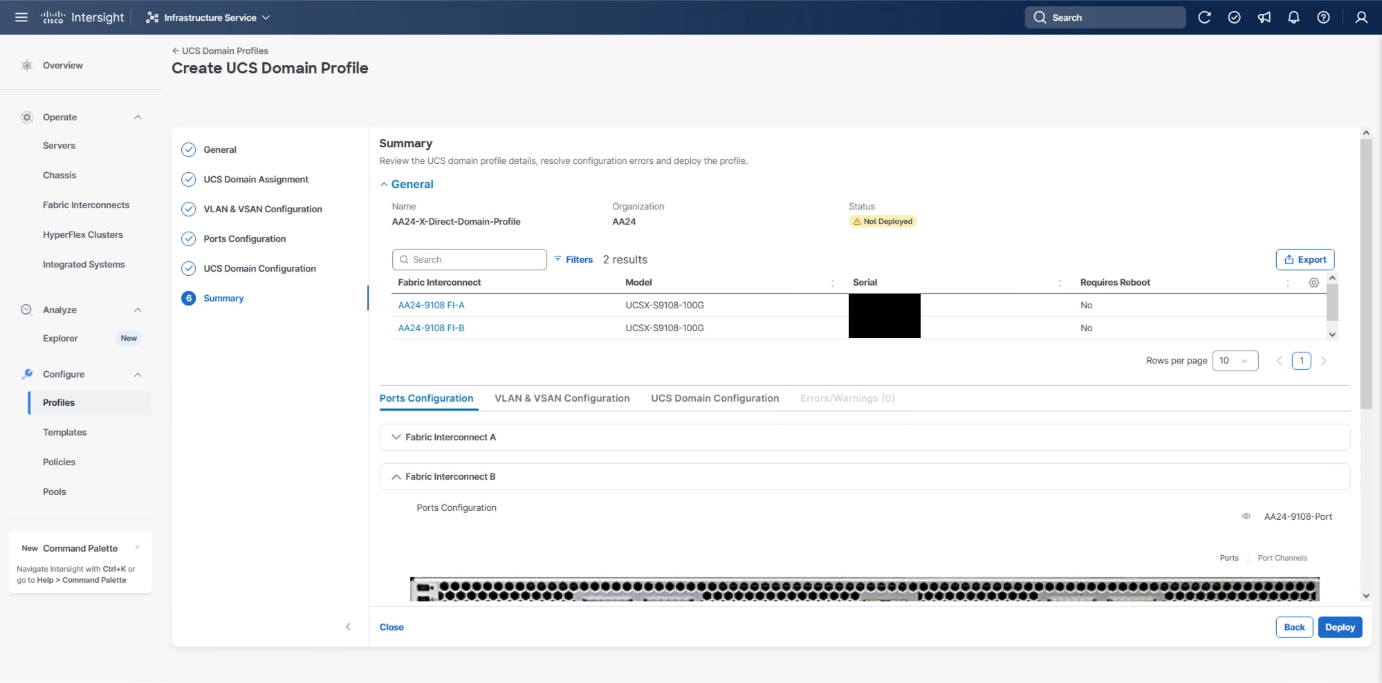
Step 2. Click Deploy.
Step 3. Acknowledge any warnings and click Deploy again.
Note: The system will take some time to validate and configure the settings on the fabric interconnects. Log into the console servers to see when the Cisco UCS fabric interconnects have finished configuration and are successfully rebooted.
Procedure 6. Verify Cisco UCS Domain Profile Deployment
When the Cisco UCS domain profile has been successfully deployed, the Cisco UCS chassis and the blades should be successfully discovered.
Note: It takes some time to discover the blades for the first time. Watch the number of outstanding requests in Cisco Intersight.
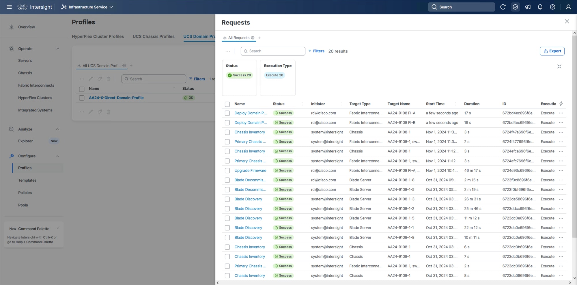
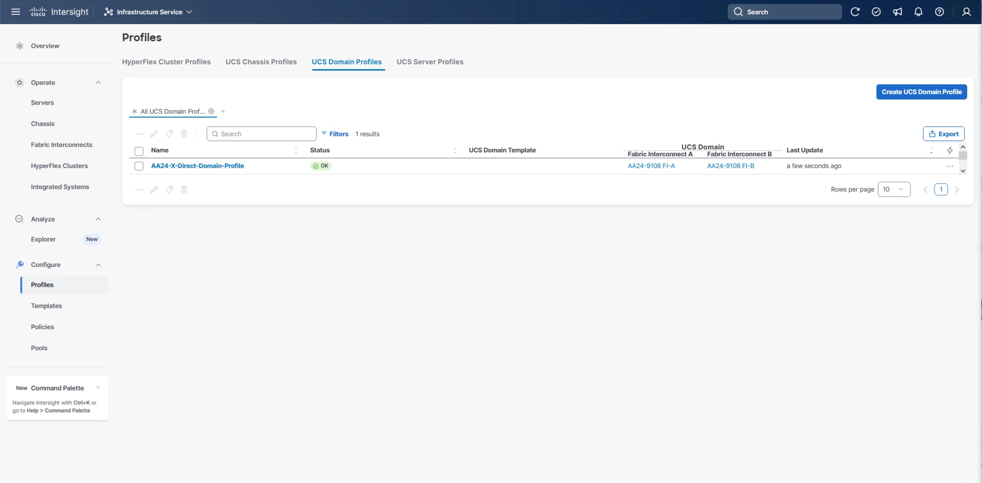
Step 1. Log into Cisco Intersight. Go to Infrastructure Service > Configure > Profiles > UCS Domain Profiles, verify that the domain profile has been successfully deployed.
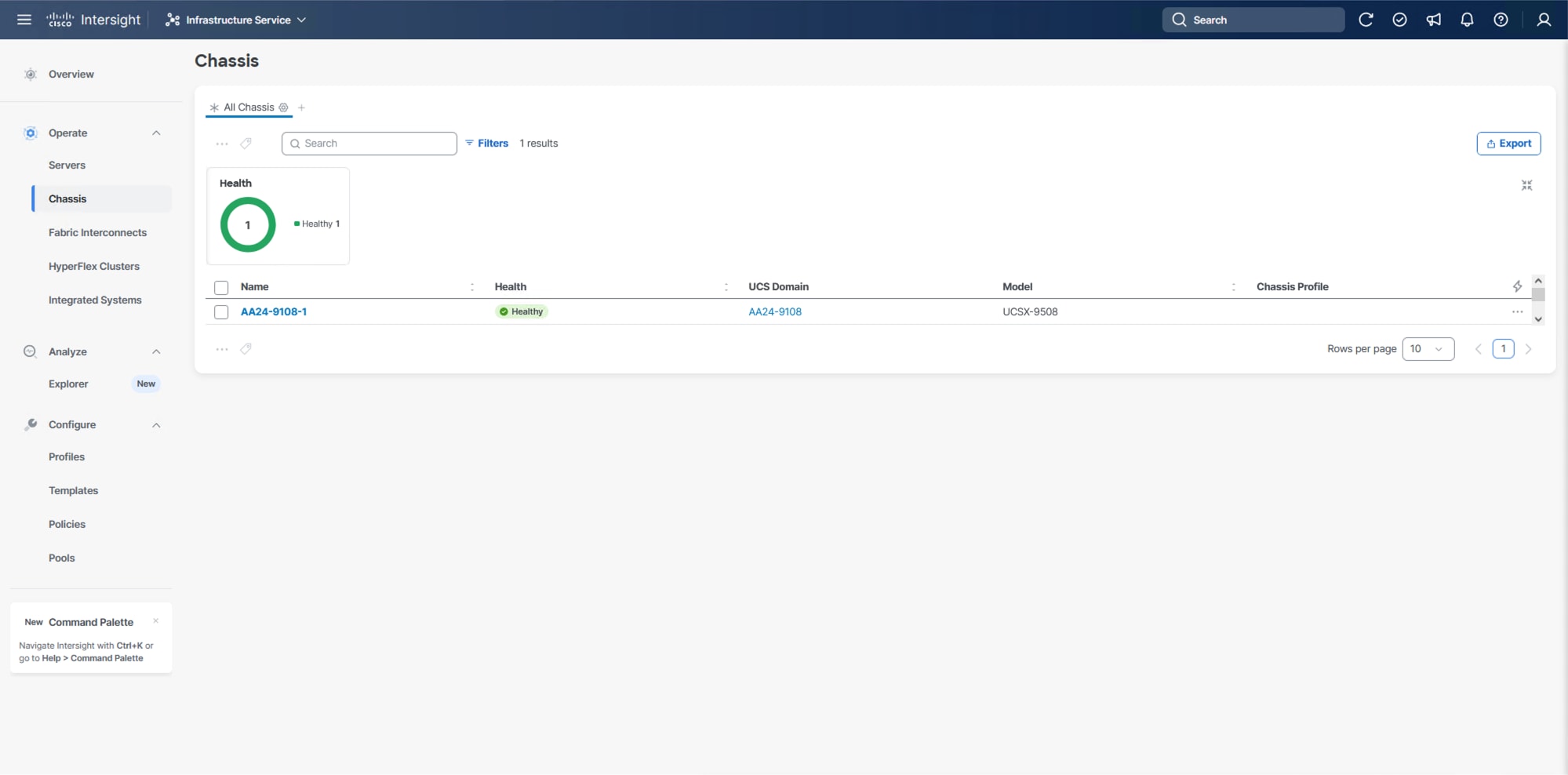
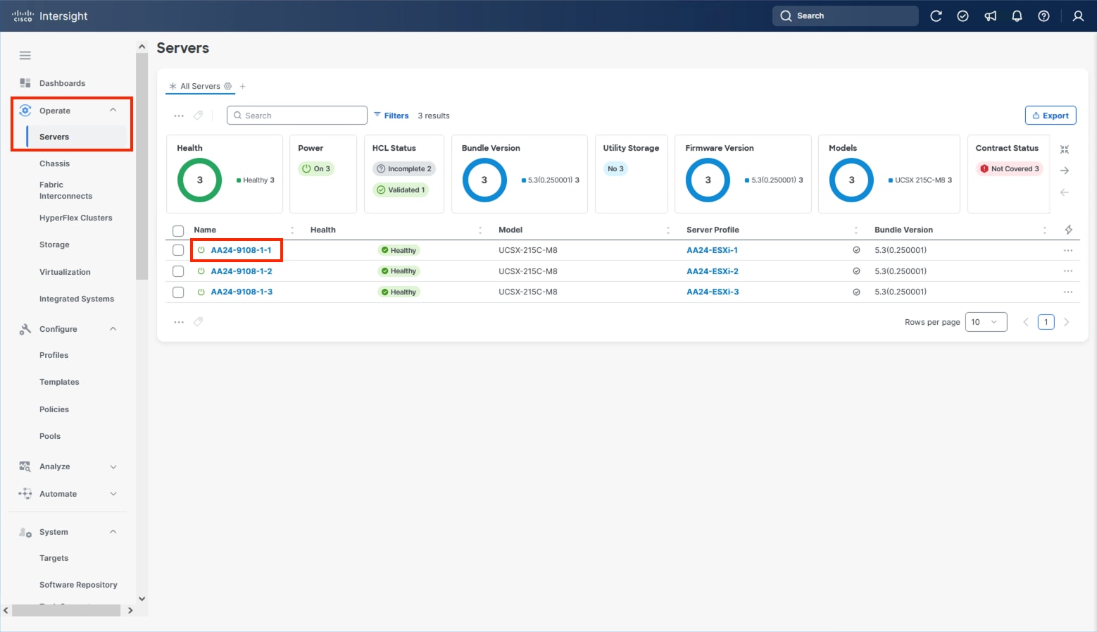
Step 2. Verify that the chassis has been discovered and is visible from Infrastructure Service > Operate > Chassis.
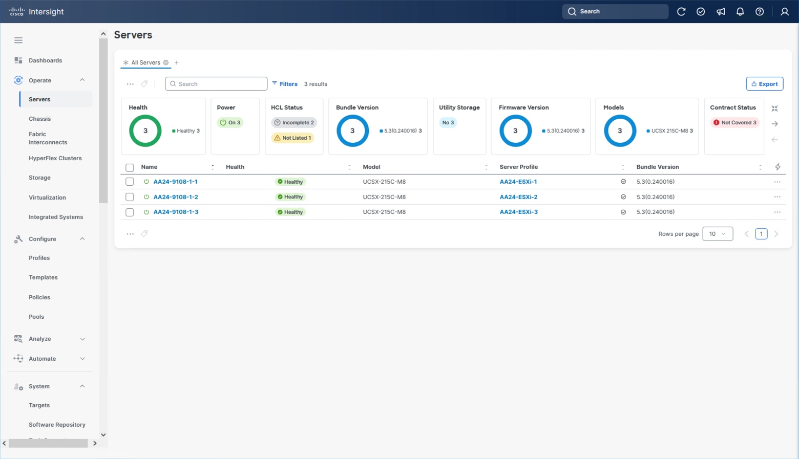
Step 3. Verify that the servers have been successfully discovered and are visible from Infrastructure Service > Operate > Servers.
Procedure 7. Update Server Firmware
Step 1. With the servers recognized, the servers can be upgraded from the most recent Servers view from Infrastructure Service > Operate > Servers.
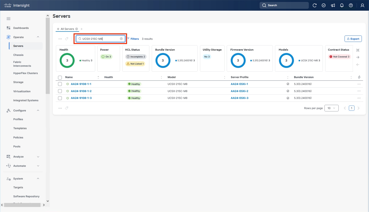
Step 2. Optionally, specify the desired model to work with from the list (example UCSX-215C-M8 if more types were present) and enter it within the filter box.
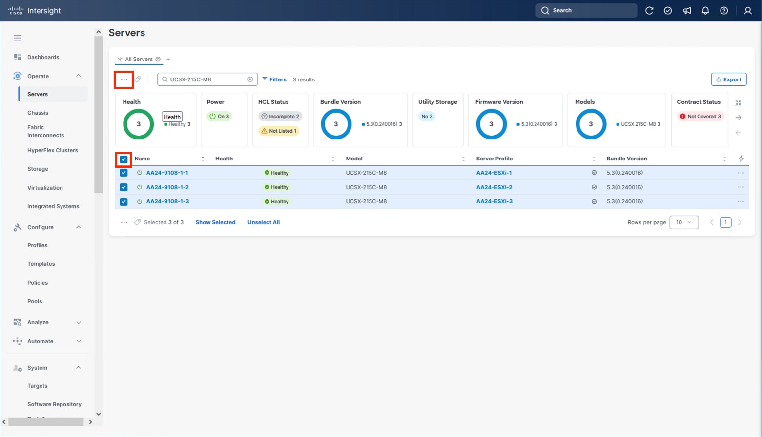
Step 3. Select all servers from the resulting list by clicking the left side box of the column header or manually select a specific set from the results.
Step 4. Click the ellipsis (…) near the top left for the drop-down list.
Step 5. Select Upgrade Firmware.
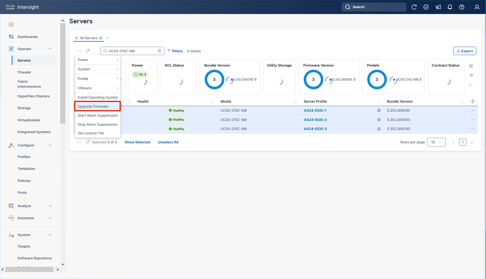
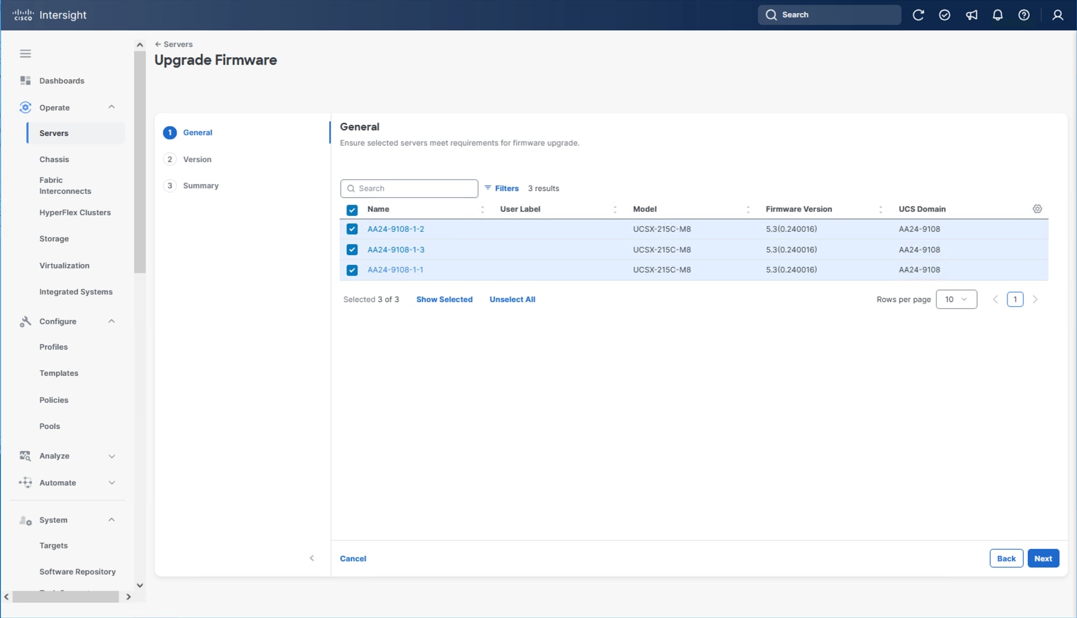
Step 6. Click Start and click Next after confirming that the servers to be upgraded have been selected.
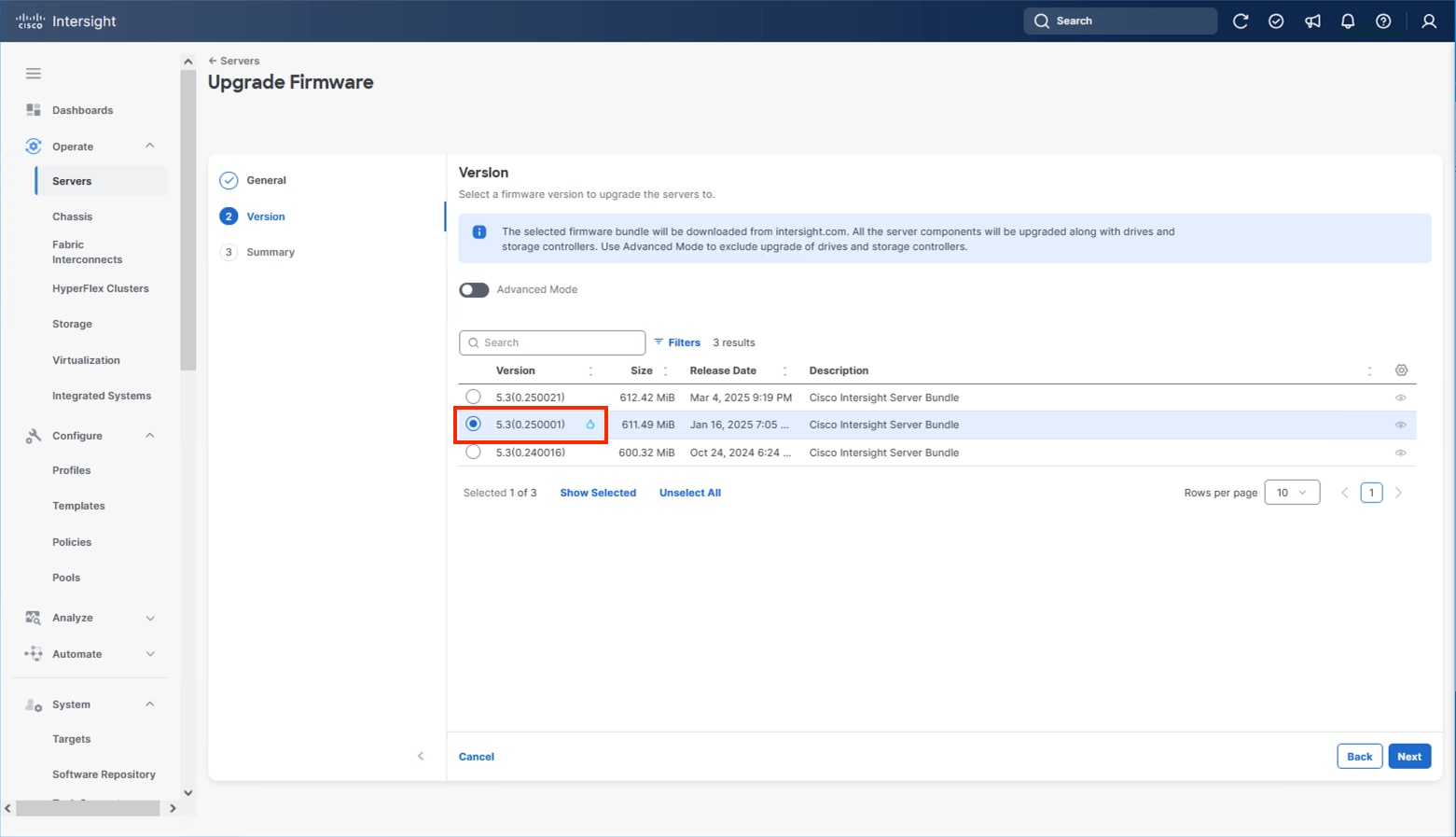
Step 7. Select the version to upgrade the servers to and click Next.
Step 8. Click Upgrade and select the toggle to Reboot Immediately to Begin Upgrade and click Upgrade again.
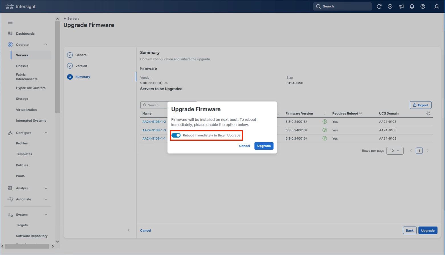
Firmware upgrade times will vary, but 30-45 minutes is a safe estimate for completion.
Configure Cisco UCS Chassis Profile (Optional)
The Cisco UCS Chassis profile in Cisco Intersight allows you to configure various parameters for the chassis, including:
● IMC Access Policy: IP configuration for the in-band chassis connectivity. This setting is independent of Server IP connectivity and only applies to communication to and from the chassis.
● SNMP Policy, and SNMP trap settings.
● Power Policy to enable power management and power supply redundancy mode.
● Thermal Policy to control the speed of fans.
A chassis policy can be assigned to any number of chassis profiles to provide a configuration baseline for a chassis. In this deployment, no chassis profile was created or attached to the chassis, but you can configure policies to configure SNMP or Power parameters and attach them to the chassis.
Configure Server Profile Template
In the Cisco Intersight platform, a server profile enables resource management by simplifying policy alignment and server configuration. The server profiles are derived from a server profile template. A server profile template and its associated policies can be created using the server profile template wizard. After creating the server profile template, you can derive multiple consistent server profiles from the template.
The server profile templates captured in this deployment guide support AMD based Cisco UCS X215c M8 compute nodes with 5th Generation VICs. AMD based Cisco UCS M8 C-Series profile templates can be nearly identical to configurations used in this document but can differ in aspects such as power policies. Intel based X-Series or B-Series servers will have some differences in BIOS policies so will generally use differing templates.
The configuration of server profiles for this IP storage-based architecture will show connectivity for NVMe/TCP storage utilizing a local M.2 boot option.
vNIC Placement for Server Profile Template
This section explains the vNIC layout used in this deployment.
Six vNICs are configured to support management, application traffic, and IP Storage traffic supporting NVMe/TCP. The vNICs are split up into pairs with the management traffic connecting to a standard vSwitch supporting the management VMkernel, the application traffic is carried on two vNICs connecting into a vSphere Distributed Switch (VDS) to carry vMotion and application traffic, and the IP storage traffic are carried on separate vNICs reflecting the A vs B traffic connecting NVMe/TCP as needed for both vSphere datastores. These devices are manually placed as listed in Table 10.
| vNIC/vHBA Name |
Slot |
Switch ID |
PCI Order |
| 00-vSwitch0-A |
MLOM |
A |
0 |
| 01-vSwitch0-B |
MLOM |
B |
1 |
| 02-VDS0-A |
MLOM |
A |
2 |
| 03-VDS0-B |
MLOM |
B |
3 |
| 04-IPStorage-A |
MLOM |
A |
4 |
| 05-IPStorage-B |
MLOM |
B |
5 |
Procedure 1. Create Server Profile Template
Step 1. Log into Cisco Intersight.
Step 2. Go to Infrastructure Service > Configure > Templates and in the main window click Create UCS Server Profile Template.
Procedure 2. General Configuration
Step 1. Select the organization from the drop-down list (for example, AA24).
Step 2. Provide a name for the server profile template. (for example, M.2-Boot-100G-IPStorage-Template)
Step 3. Select UCS Server (FI-Attached).
Step 4. Provide a description (optional).
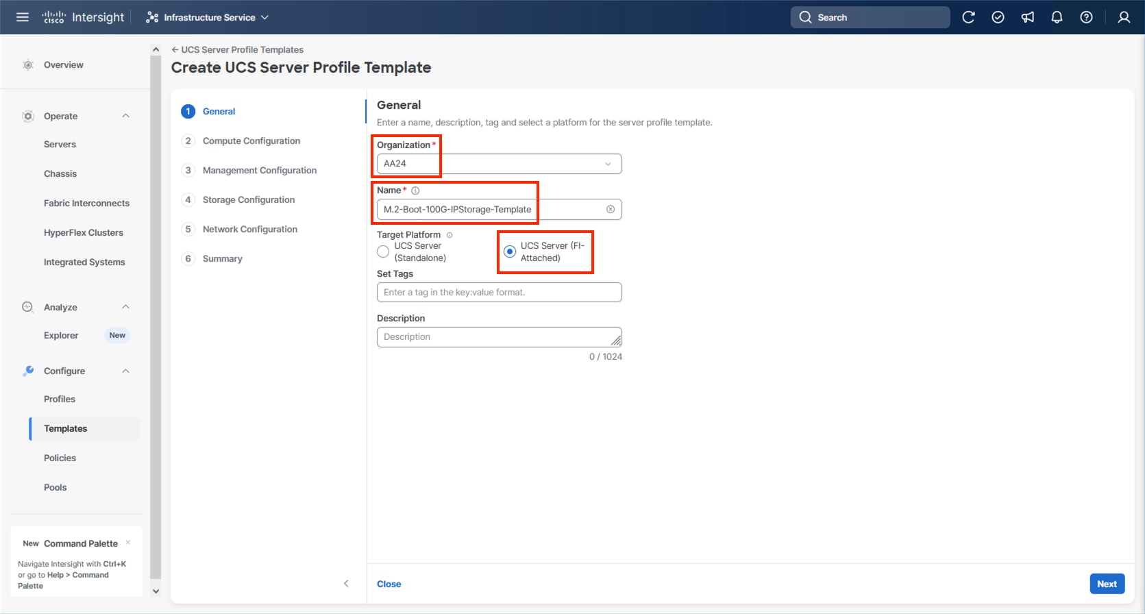
Step 5. Click Next.
Compute Configuration
The following subcomponents of pools and policies will be addressed in the Compute Configuration:
● A UUID Pool will be created to be used for the identities of Server Profiles derived from the Server Profile Template
● A BIOS Policy to set the available settings for the underlying hardware of the UCS Compute Nodes
● A Boot Order Policy to set the boot order of the Compute Nodes
● A Virtual Media Policy to enable virtual media accessibility to the KVM
Procedure 1. Configure UUID Pool
Step 1. Click Select Pool under UUID Pool and then in the pane on the right, click Create New.
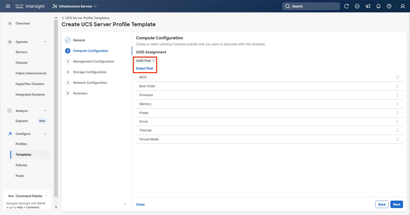
Step 2. Verify that the correct organization is selected from the drop-down list (for example, AA24) and provide a name for the UUID Pool (for example, AA24-UUID-Pool).
Step 3. Provide a Description (optional) and click Next.
Step 4. Provide a hexadecimal UUID Prefix (for example, a prefix of AA240000-0000-0001 was used).
Step 5. Add a UUID block specifying a From starting value (example AA24-000000000001) and a Size.
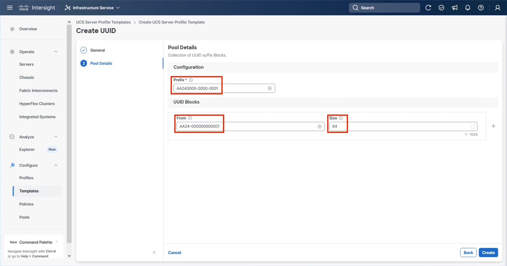
Step 6. Click Create.
Procedure 2. Configure BIOS Policy
Step 1. Click Select Policy next to BIOS and in the pane on the right, click Create New.
Step 2. Verify that the correct organization is selected from the drop-down list (for example, AA24) and provide a name for the policy (for example, AA24-AMD-M8-VSI-BIOS).
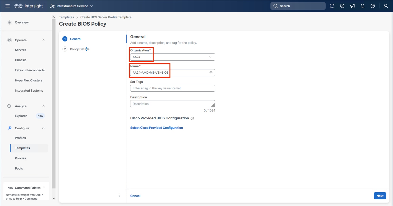
Note: At the time of this publication, there is not a Cisco Provided BIOS Configuration option for the AMD M8 servers within Intersight, so a manual configuration will be used.
Step 3. Click Next.
Step 4. From the Policy Details screen, select the appropriate values for the BIOS settings. In this deployment, the BIOS values were selected based on recommendations in the Performance Tuning for Cisco UCS M8 Platforms with AMD EPYC 4th Gen and 5th Gen Processors guide for Cisco UCS M8 BIOS published for the Cisco UCS C245 M8 servers. The platform defaults will primarily align with recommendations for virtual workloads, so adjust the parameter shown below and leave all other parameters set to platform-default.
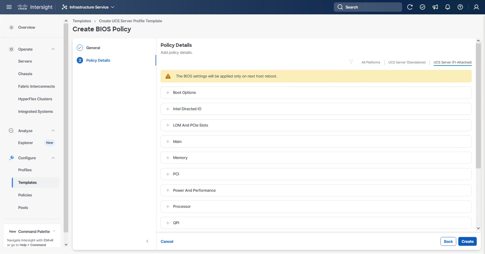
Step 5. Go to Power and Performance > CPPC: Enabled.
Step 6. Click Create.
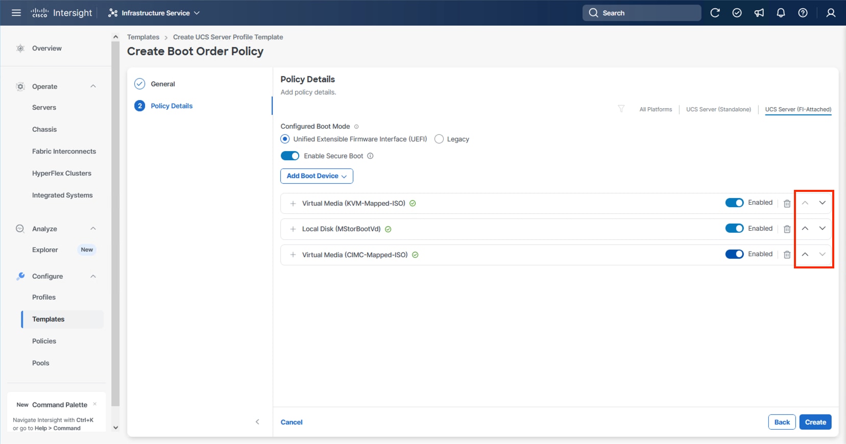
Procedure 3. Configure Boot Order Policy
The M.2 boot option, as a local boot option, is recommended within this design. Identification of the storage controller ID will be needed for this configuration.
Step 1. Without closing your configuration dialogue, open a new tab or window by right-clicking Servers on the left side from the Operate section of your Intersight browser and select the link.
Step 2. From the new tab or window, go to Operate > Servers and click one of your servers.
Step 3. From the server view, go to Inventory > Storage Controllers and select the RAID controller and confirm the ID name associated with it.
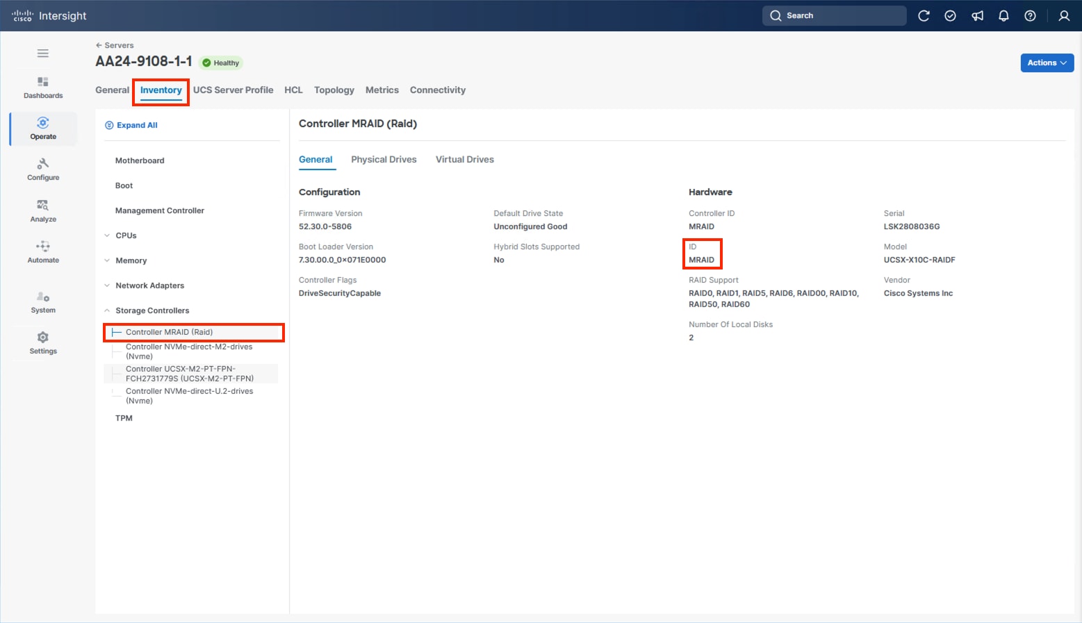
Step 4. Go to the Server Profile Template browser window.
Step 5. Click Select Policy next to Boot Order and in the right pane click Create New.
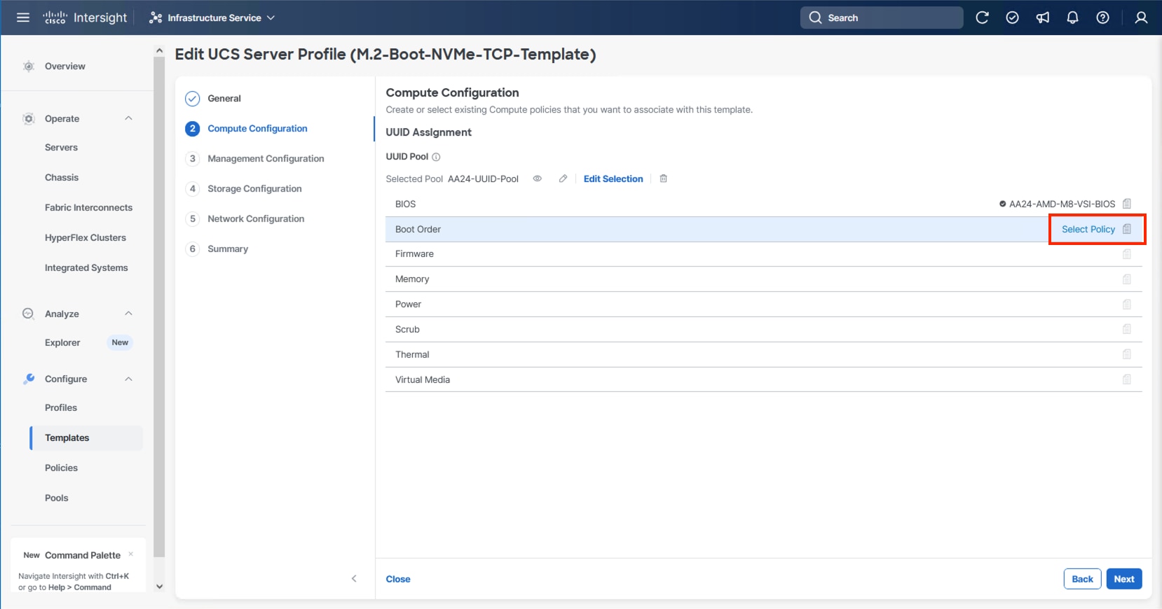
Step 6. Verify that the correct organization is selected from the drop-down list (for example, AA24) and provide a name for the policy (for example, AA24-M.2-MSTOR-Boot-Order).
Step 7. Click Next.
Step 8. For Configured Boot Mode, select Unified Extensible Firmware Interface (UEFI).
Step 9. Turn on Enable Secure Boot.
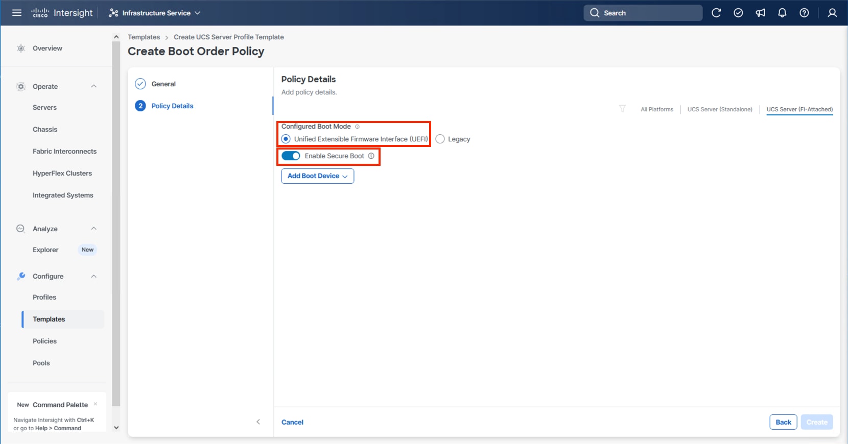
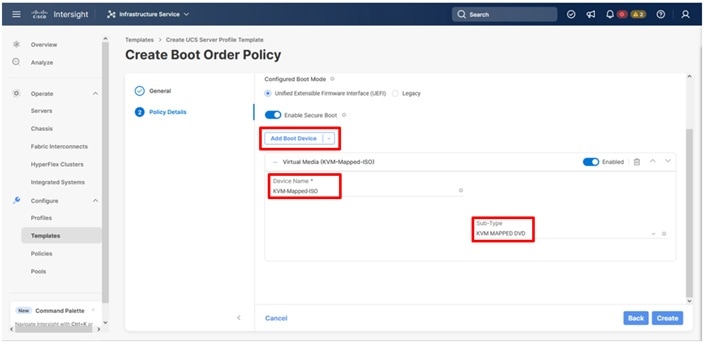
Step 10. From the Add Boot Device drop-down list, select Virtual Media.
Step 11. Provide a Device Name (for example, KVM-Mapped-ISO) and for the Sub-Type, select KVM Mapped DVD.
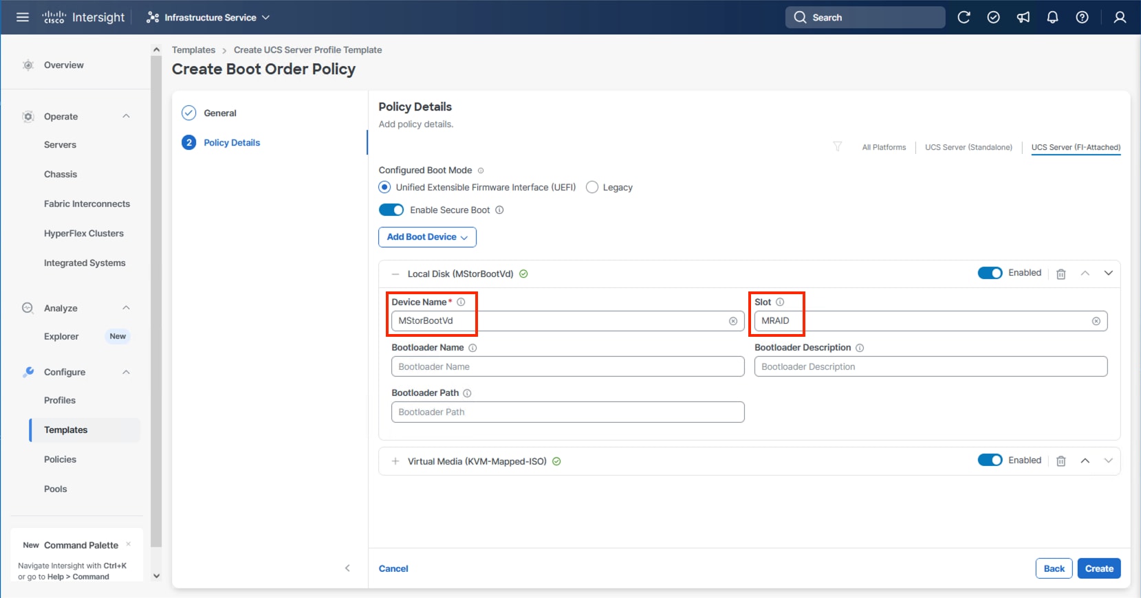
Step 12. From the Add Boot Device drop-down list, select Local Disk.
Step 13. Enter MStorBootVd (this will be used later for the Storage Policy created) for the Device Name and enter the ID found from the server Storage Controller in Step 3 for the Slot.
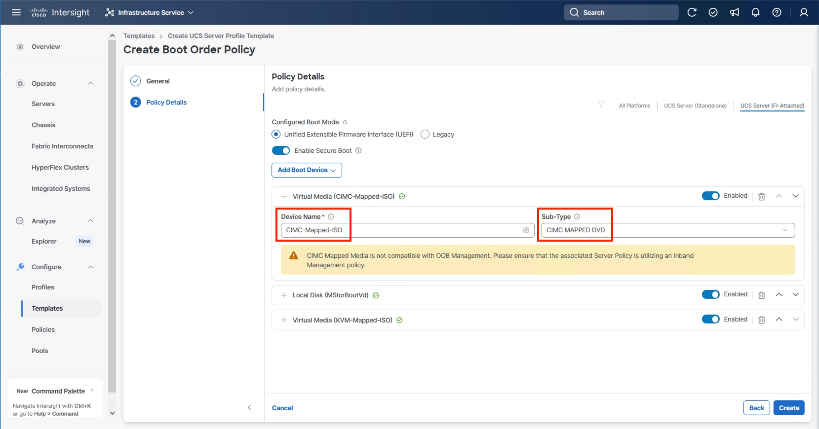
Step 14. (Optional) From the Add Boot Device drop-down list and select Virtual Media again to add a CIMC boot option providing an option to boot from ISO defined within the vMedia policy.
Step 15. Use the up/down arrows of each defined boot device to create the order that will be checked at boot time and click Create.
Procedure 4. Configure Power Policy
The Power Policy will be used to set the state when bringing up the nodes in the event of a loss of power.
Step 1. Click Select Policy next to Power and click Create Policy.
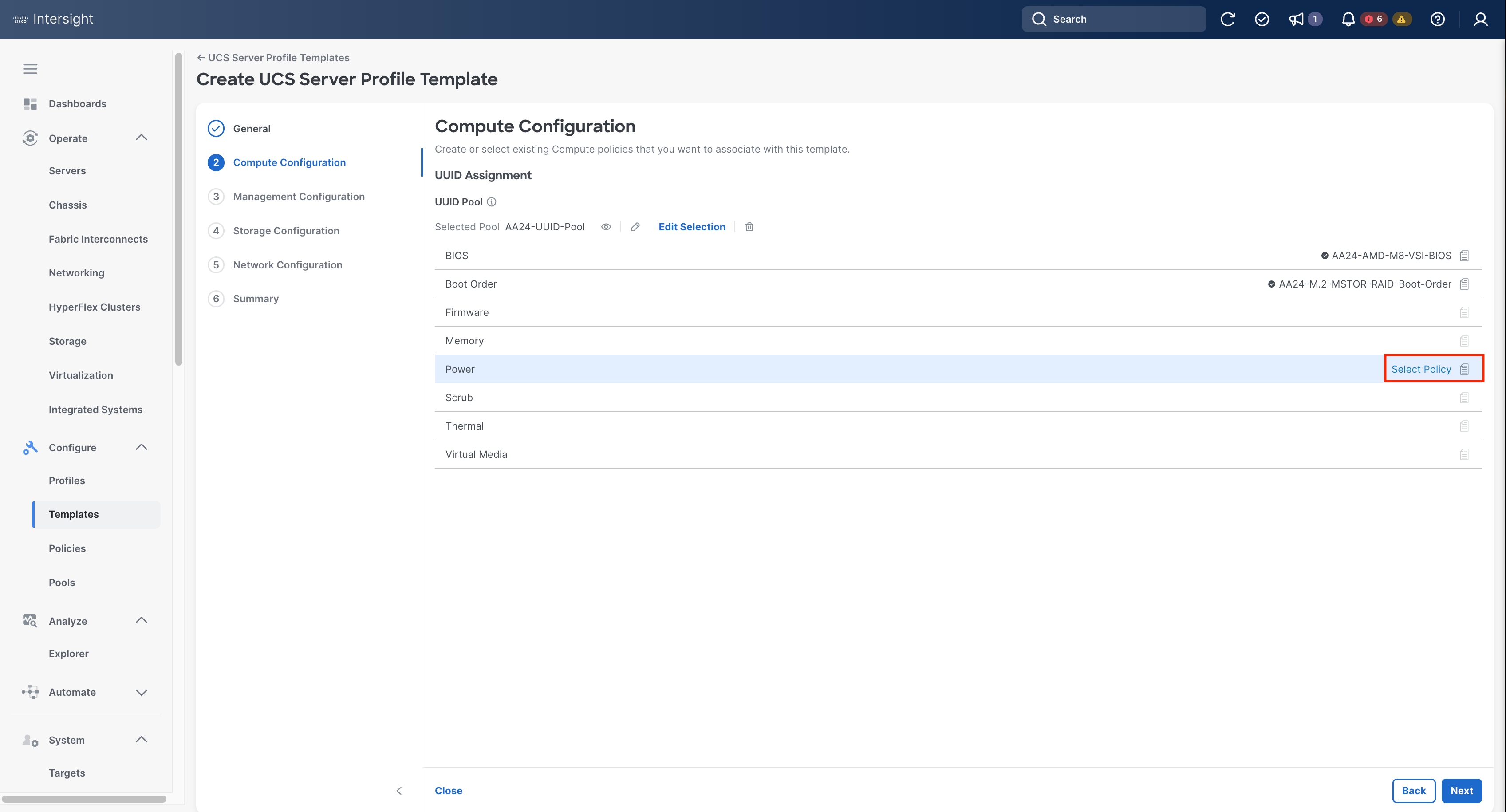
Step 2. Verify that the correct organization is selected from the drop-down list (for example, AA24) and provide a name for the policy (for example, AA24-NodePower).
Step 3. From the Power Restore drop-down list, select Last State.
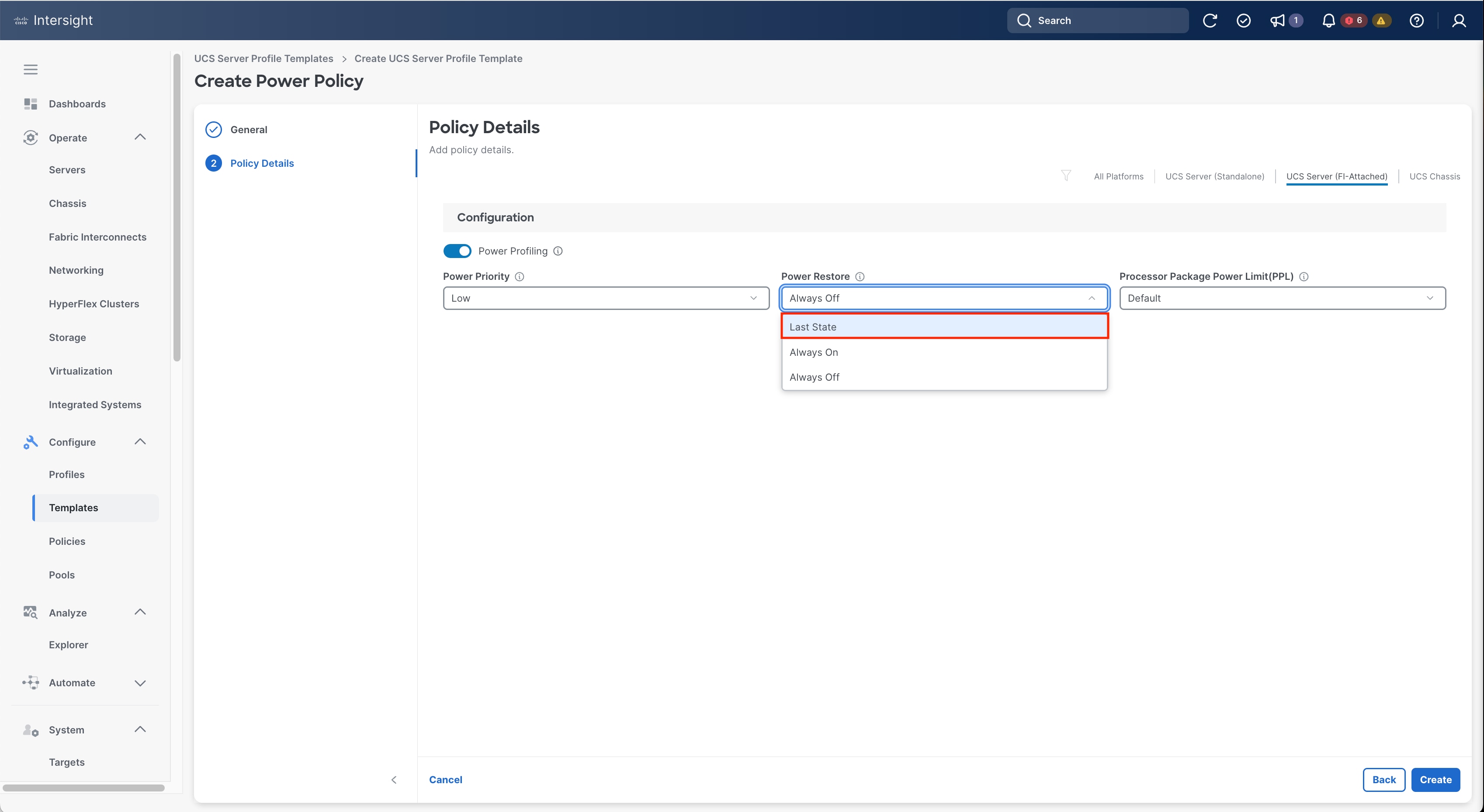
Step 4. Click Create.
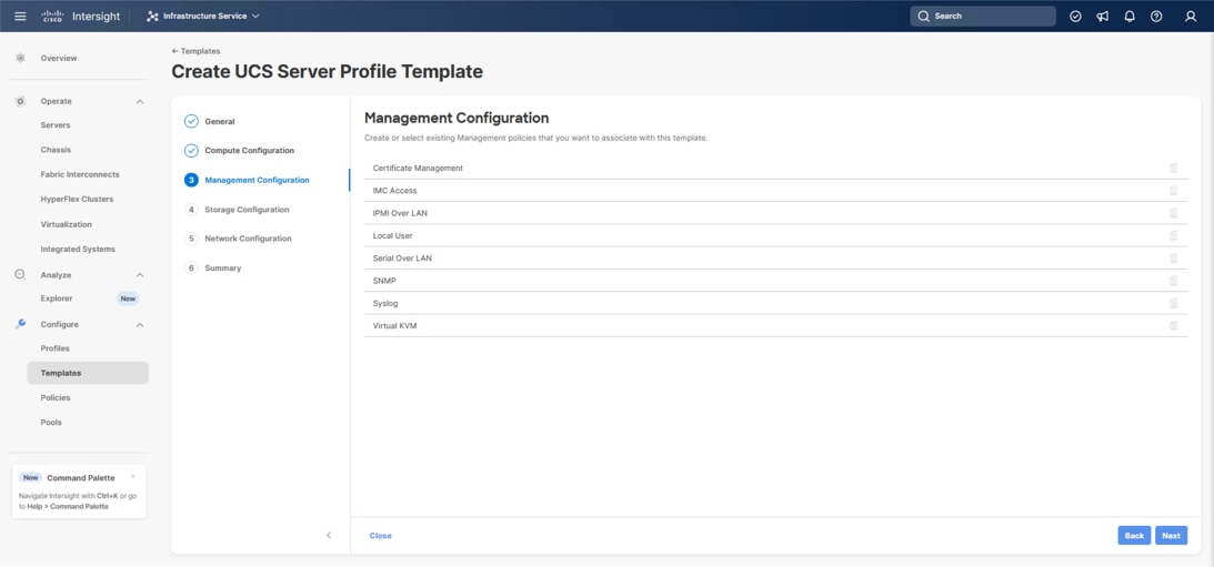
The following policies will be added to the management configuration:
● IMC Access to define the pool of IP addresses for compute node KVM access
● IPMI Over LAN to allow Intersight to manage IPMI messages
● Virtual KVM to allow the Tunneled KVM
Procedure 1. Configure Cisco IMC Access Policy
Step 1. Click Select Policy next to IMC Access and click Create New.
Step 2. Verify that the correct organization is selected from the drop-down list (for example, AA24) and provide a name for the policy (for example, AA24-IMC-Access-Policy).
Step 3. Click Next.
Step 4. Click UCS Server (FI-Attached) if not selected.
Step 5. Leave the toggle to enable In-Band Configuration and specify the VLAN ID to use for the IB-Mgmt or other network to use for the IMC connectivity.
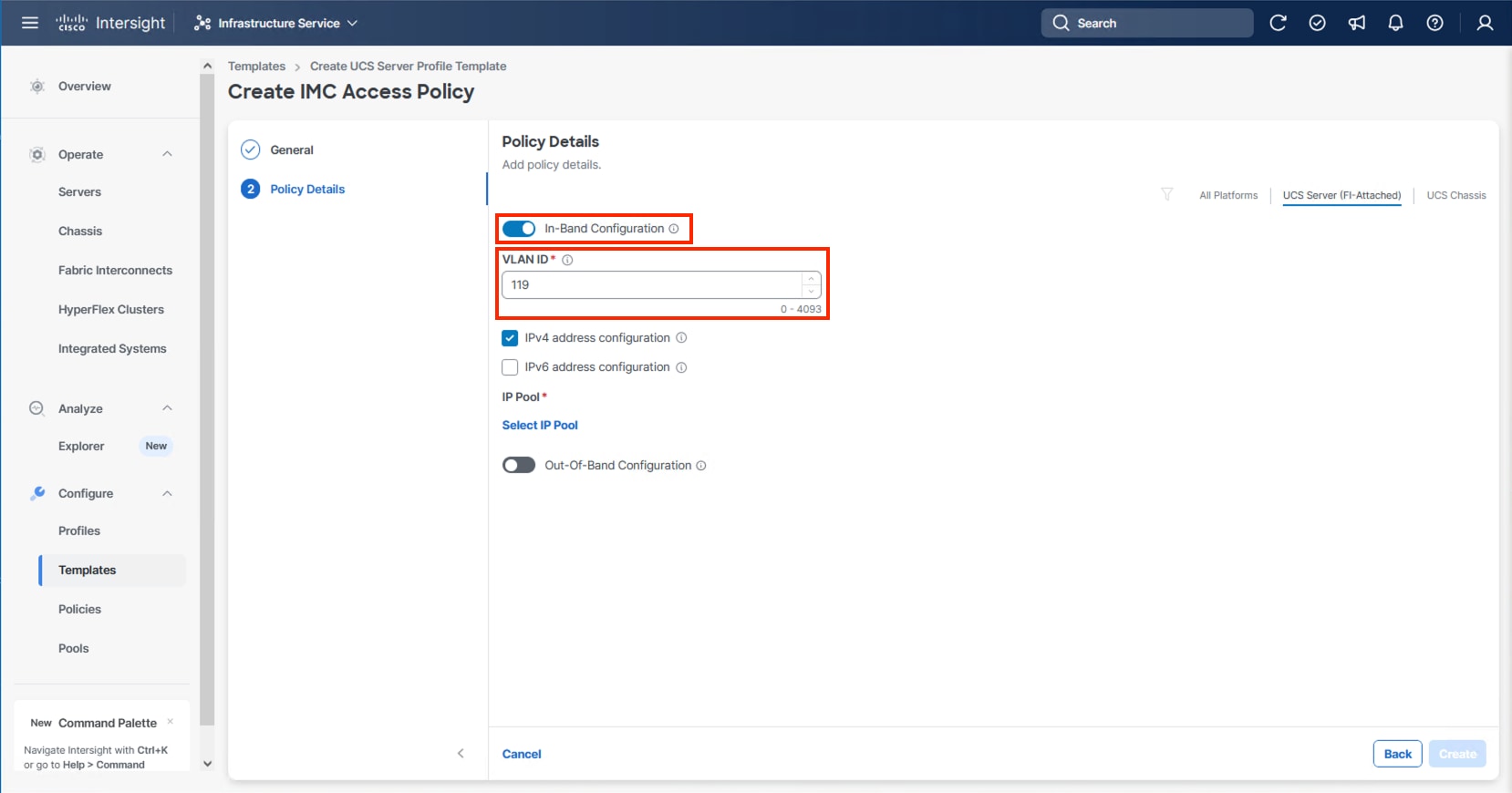
Note: Deselecting In-Band Configuration will bring up the option to enable Out-Of-Band Configuration within the IMC Access Policy. An Out-Of-Band Configuration can be used for IMC and KVM connectivity out of the management network of the fabric interconnect. If Out-Of-Band is used, there will not be a VLAN specification, and CIMC vMedia will not be possible.
Step 6. Click Select IP Pool and click Create New.
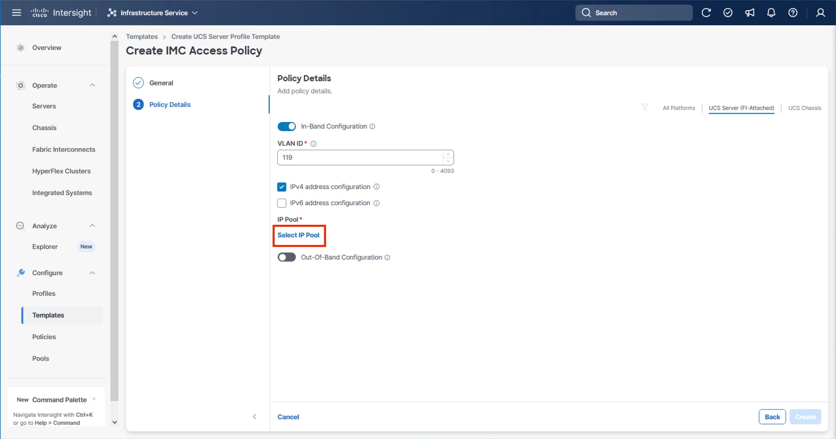
Step 7. Verify that the correct organization is selected from the drop-down list (for example, AA24) and provide a name for the policy (for example, AA24-IB-Mgmt-Pool). Click Next.
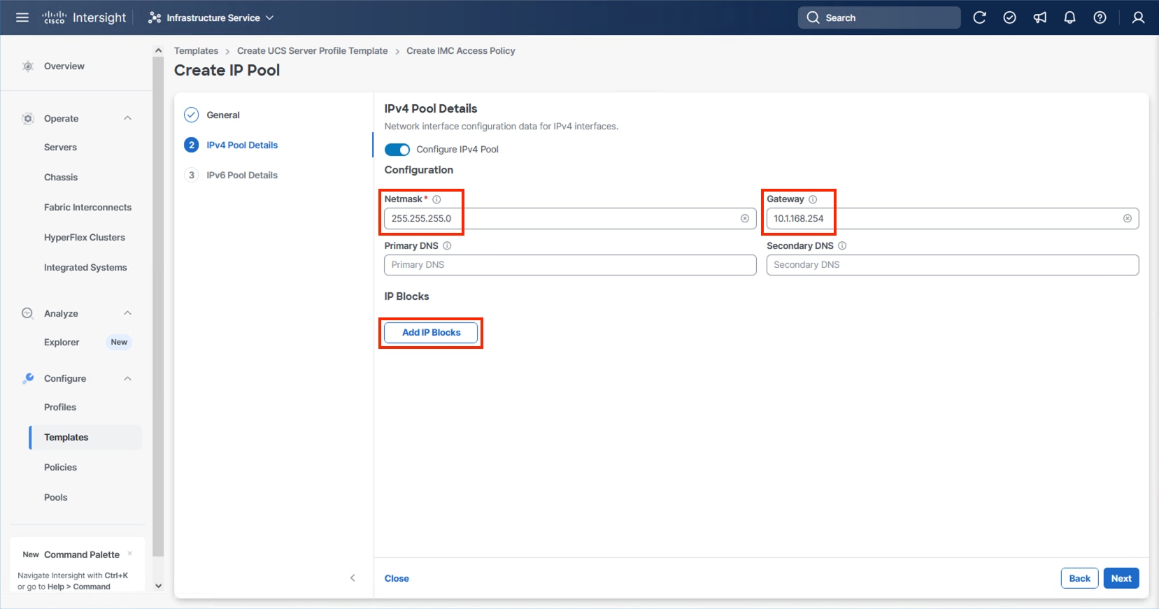
Step 8. Enter the appropriate Netmask and Gateway for the IPv4 Pool and click Add IP Blocks.
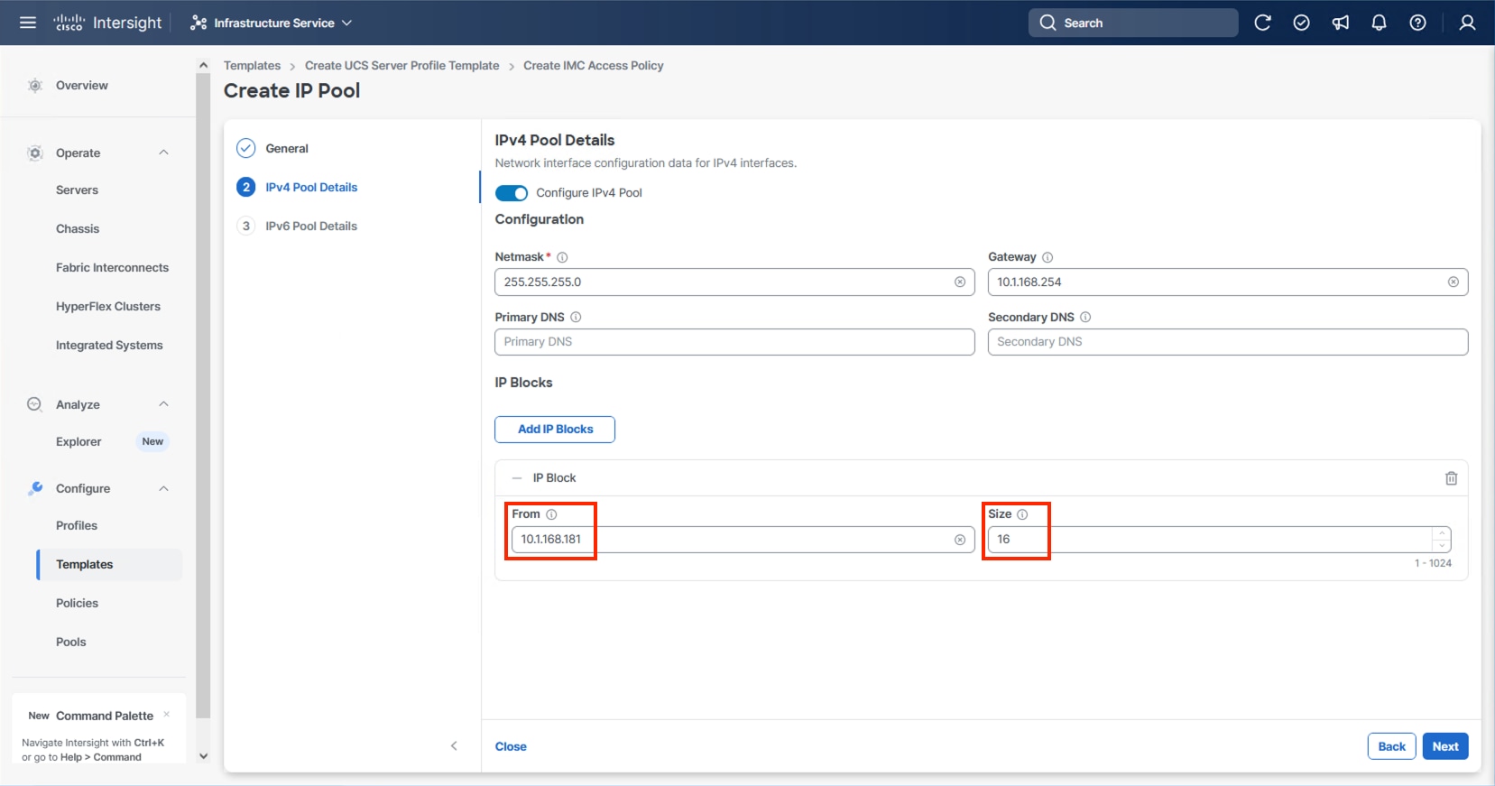
Step 9. Specify a starting IP for the block in From and a Size for the block. Click Add IP Blocks if you want to create multiple blocks within the In-Band network.
Step 10. Click Next and deselect the Configure IPv6 Pool option unless appropriate and click Create.
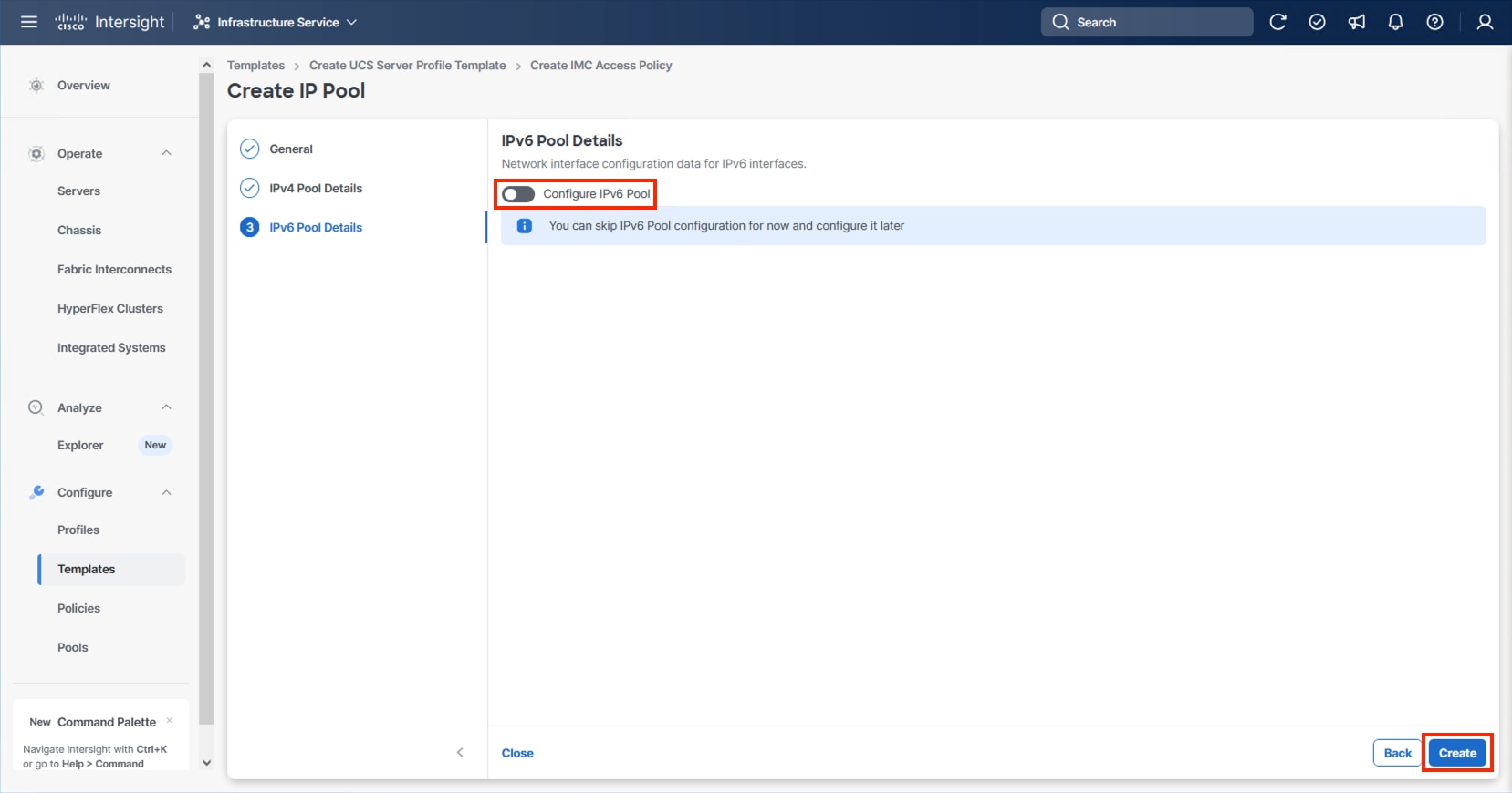
Step 11. Click Create to finish configuring the IMC access policy.
Procedure 2. Configure IPMI Over LAN Policy
Step 1. Click Select Policy next to IPMI Over LAN and click Create New.
Step 2. Verify that the correct organization is selected from the drop-down list (for example, AA24) and provide a name for the policy (for example, AA24-Enable-IPMIoLAN-Policy).
Step 3. Click Next.
Step 4. Leave the default settings in place for this policy.
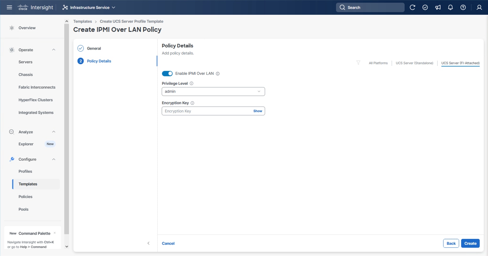
Step 5. Click Create.
Procedure 3. Configure Local User Policy
Step 1. Click Select Policy next to Local User and click Create New.
Step 2. Verify that the correct organization is selected from the drop-down list (for example, AA24) and provide a name for the policy (for example, AA24-LocalUser).
Step 3. Verify that Enforce Strong Password is selected.
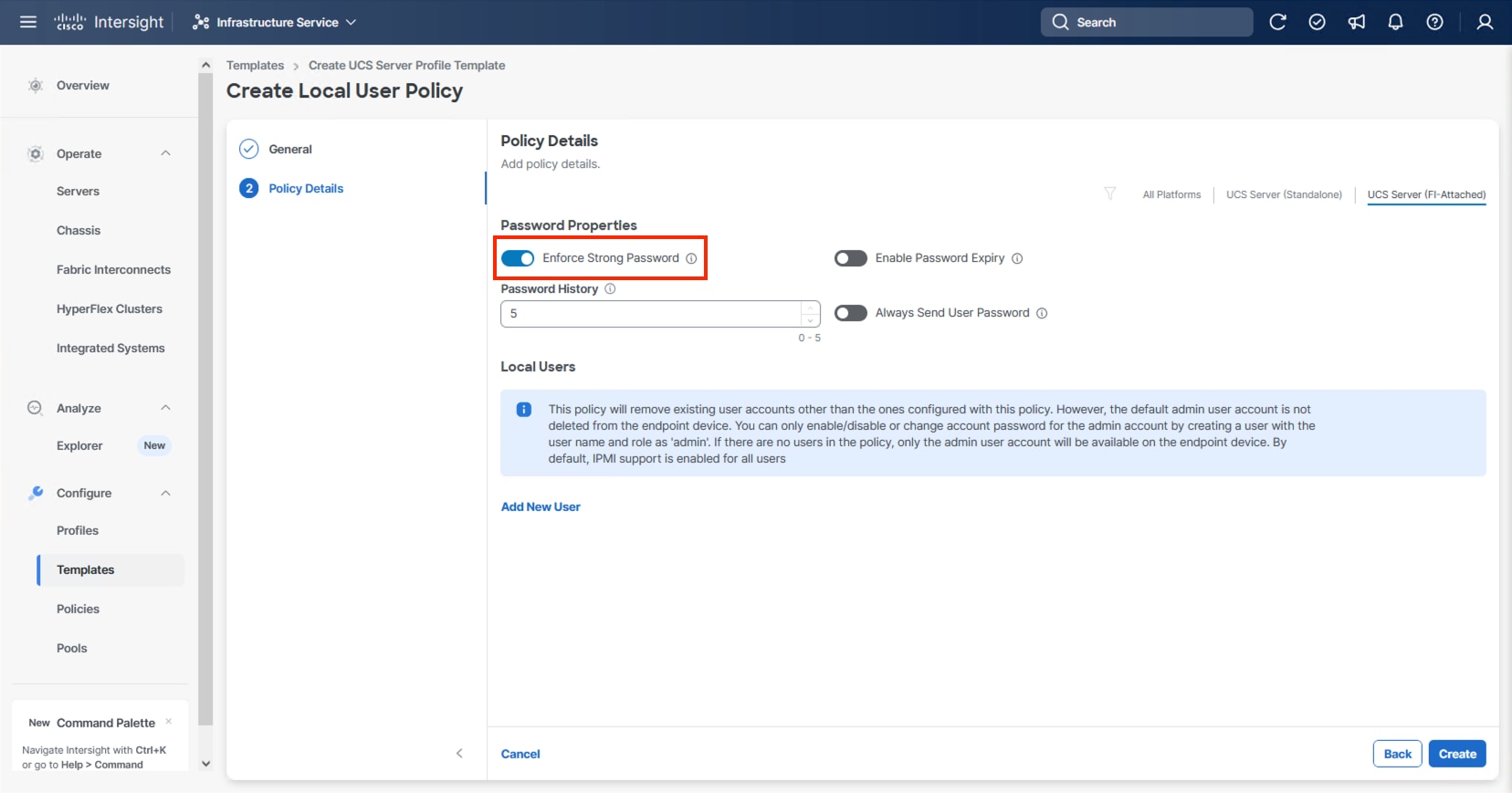
Step 4. Click Add New User and then click + next to the New User.
Step 5. Provide a username (for example, vsiuser), choose a role (for example, admin), and provide a password.
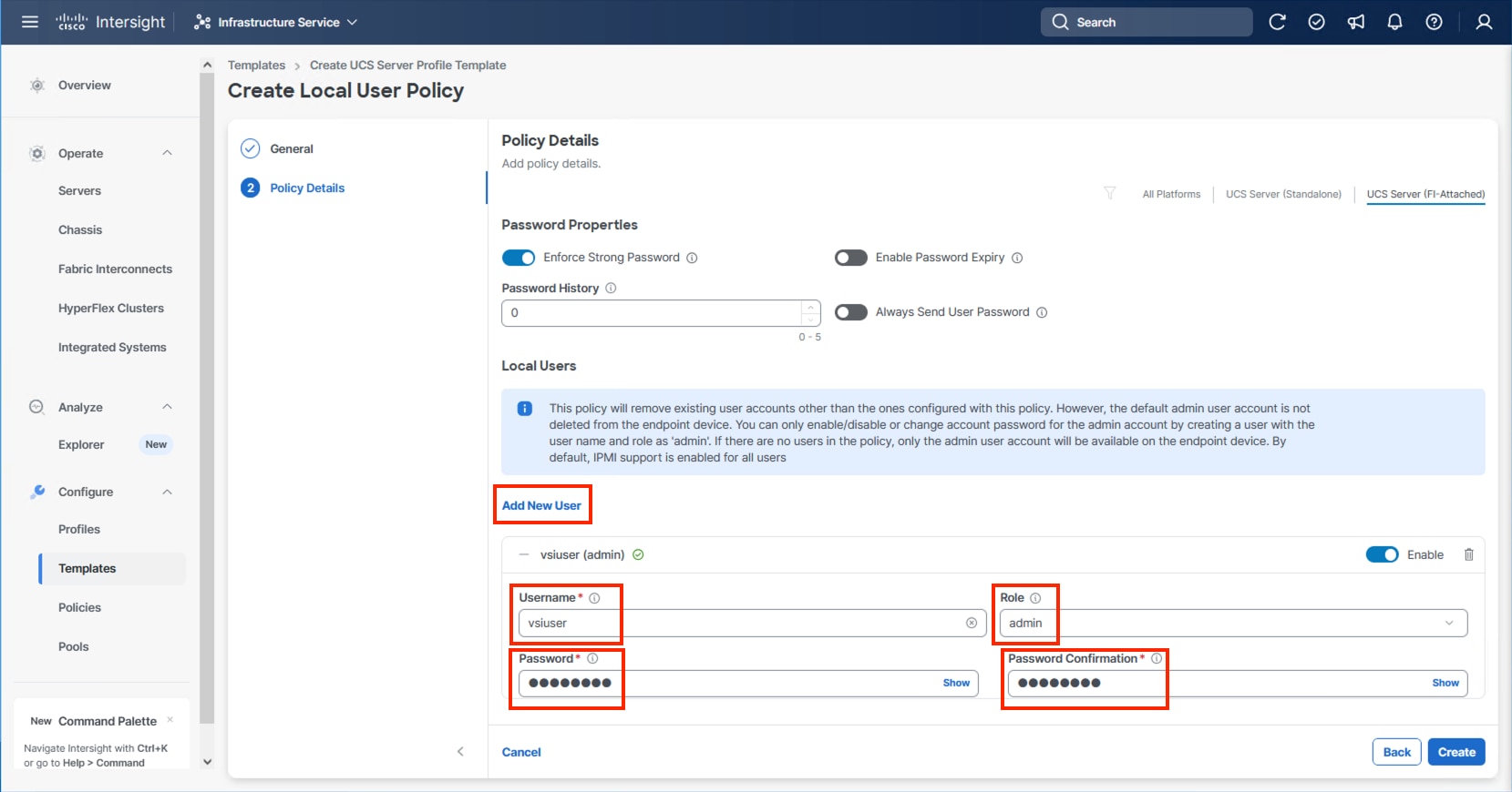
Note: The username and password combination defined here will be used as an alternate to log in to KVMs and can be used for IPMI.
Step 6. Click Create to finish configuring the user.
Step 7. Click Create to finish configuring the Local User Policy.
Procedure 4. Configure Virtual KVM Policy
Step 1. Click Select Policy next to Virtual KVM and click Create New.
Step 2. Verify that the correct organization is selected from the drop-down list (for example, AA24) and provide a name for the policy (for example, AA24-KVM-Policy).
Step 3. Turn on Allow Tunneled vKVM.
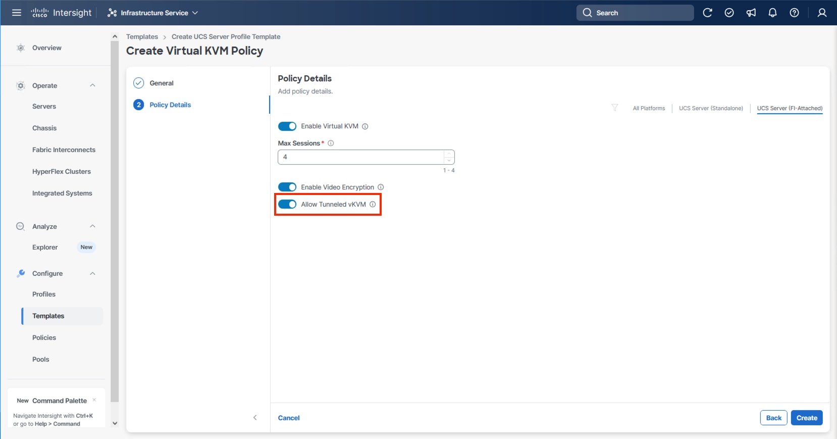
Step 4. Click Create.
Note: To fully enable Tunneled KVM, after the Server Profile Template has been created, go to System > Settings > Security and Privacy and click Configure. Turn on Allow Tunneled vKVM Launch and Allow Tunneled vKVM Configuration.
Step 5. Click Next to continue to Storage Configuration.
Storage Configuration
The Storage Configuration section of the Server Profile Template is required for configuring internal storage in the UCS servers using M.2 boot.
Procedure 1. Create Storage Configuration
Step 1. Click Select Policy and click Create New.
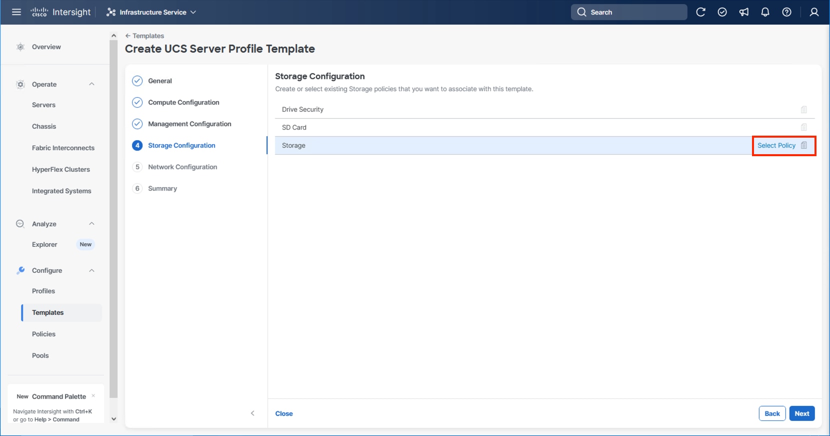
Step 2. Verify that the correct organization is selected from the drop-down list (for example, AA24) and provide a name for the policy (for example, AA24-Storage-Policy).
Step 3. Click Next.
Step 4. Enable M.2 RAID Configuration.
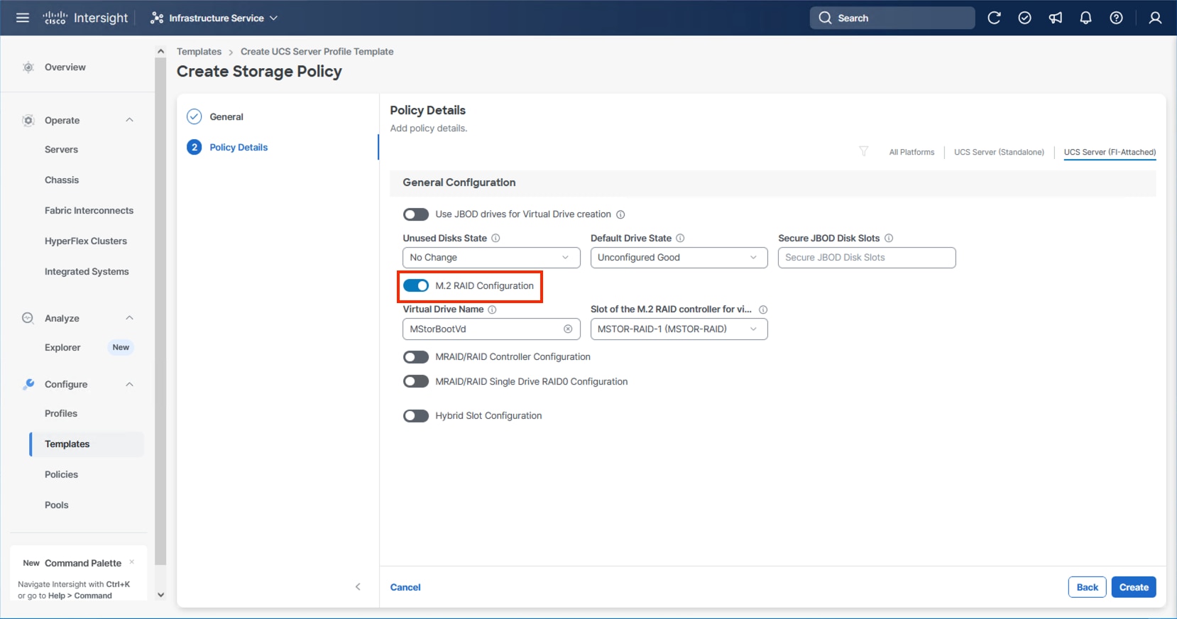
Step 5. Leave the default Virtual Drive Name and leave Slot of the M.2 RAID controller selected as MSTOR-RAID-1. Click Create.
Step 6. Click Next on the Storage Configuration screen.
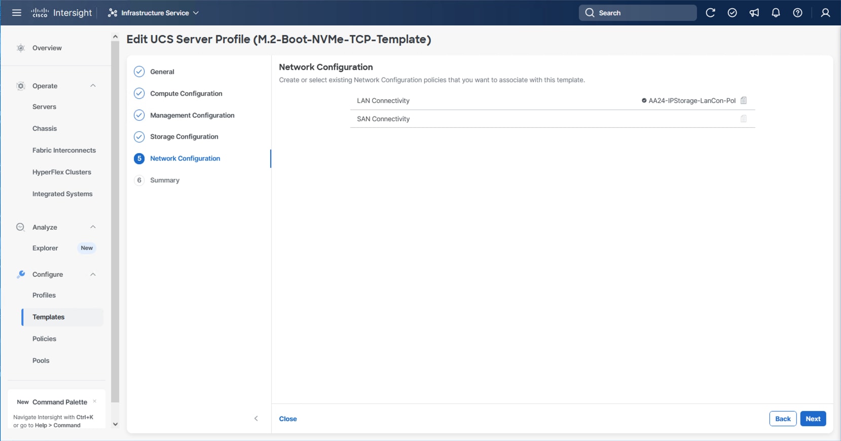
This section details how to create the LAN Connectivity policy used by the derived Server Profiles.
LAN Connectivity
Procedure 1. Create Network Configuration - LAN Connectivity Policy
The LAN connectivity policy defines the connections and network communication resources between the server and the LAN. This policy uses pools to assign MAC addresses to servers and to identify the vNICs that the servers use to communicate with the network.
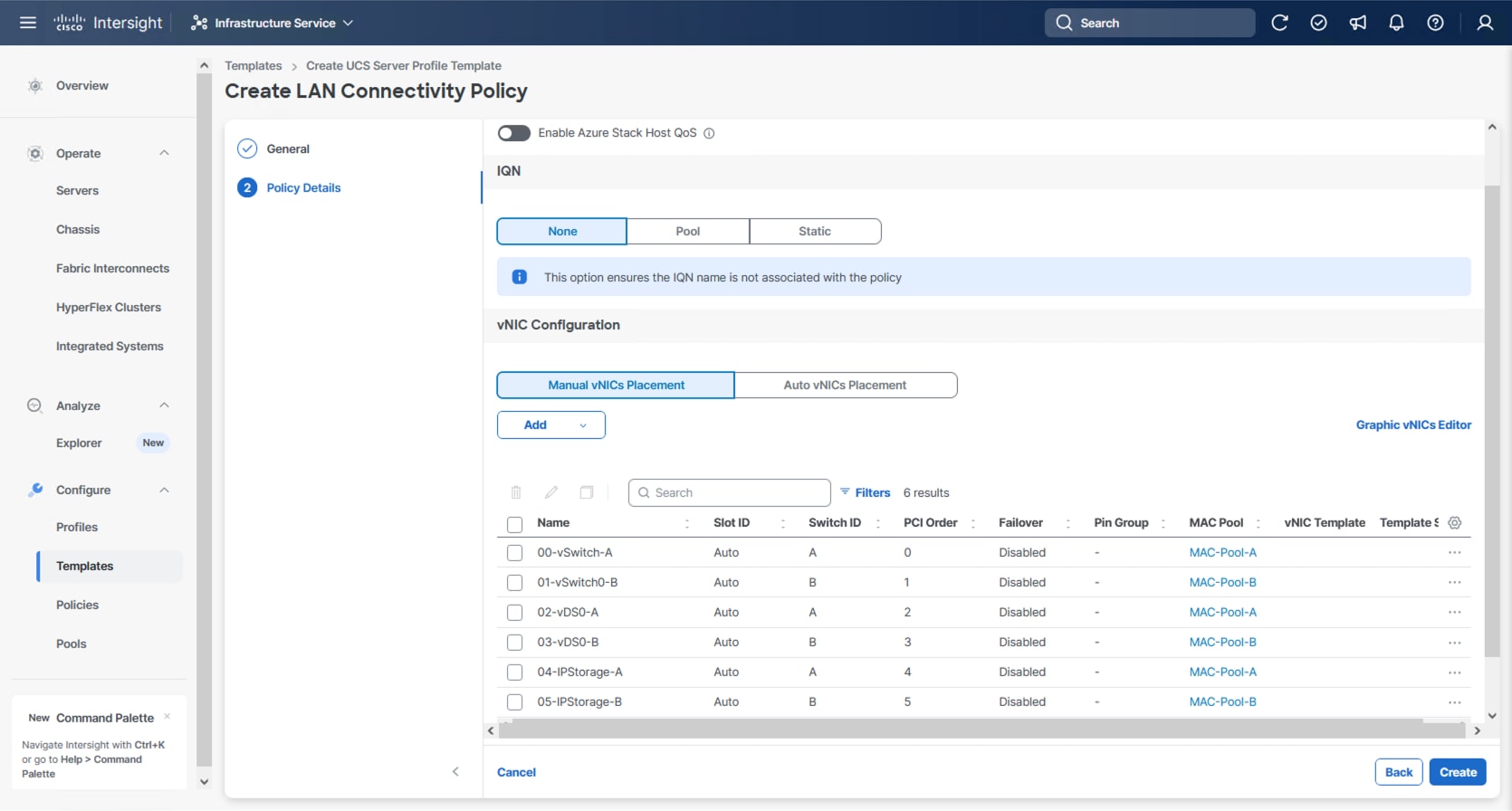
For consistent vNIC placement, manual vNIC placement is used. The six vNICs configured are listed in Table 11.
Table 11. vNICs defined in LAN Connectivity
| vNIC/vHBA Name |
Slot ID |
Switch ID |
PCI Order |
VLANs |
| 00-vSwitch0-A |
MLOM |
A |
0 |
IB-Mgmt |
| 01-vSwitch0-B |
MLOM |
B |
1 |
IB-Mgmt |
| 02-vDS0-A |
MLOM |
A |
2 |
IB-Mgmt, VM Traffic, VM Traffic-A, VM Traffic-B, vMotion |
| 03-vDS0-B |
MLOM |
B |
3 |
IB-Mgmt, VM Traffic, VM Traffic-A, VM Traffic-B, vMotion |
| 04-IPStorage-A |
MLOM |
A |
4 |
NVMe-TCP-A |
| 05-IPStorage-B |
MLOM |
B |
5 |
NVMe-TCP-B |
Step 1. Click Select Policy next to LAN Connectivity and click Create New from the column that appears to the right.
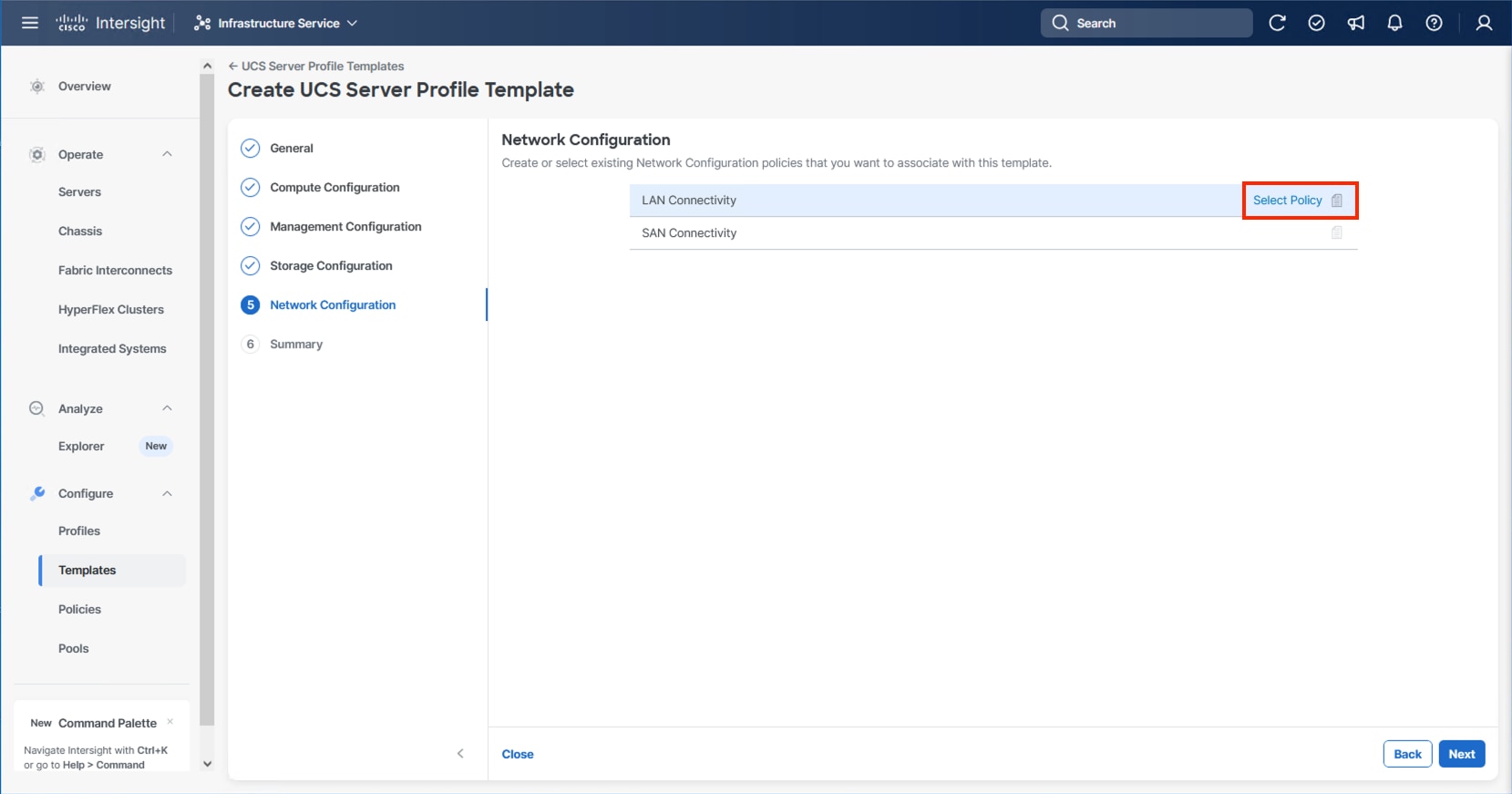
Step 2. Verify that the correct organization is selected from the drop-down list (for example, AA24) and provide a name for the policy (for example, AA24-IPStorage-LanCon). Click Next.
Step 3. In the vNIC Configuration section, from the Add drop-down list, select vNIC.
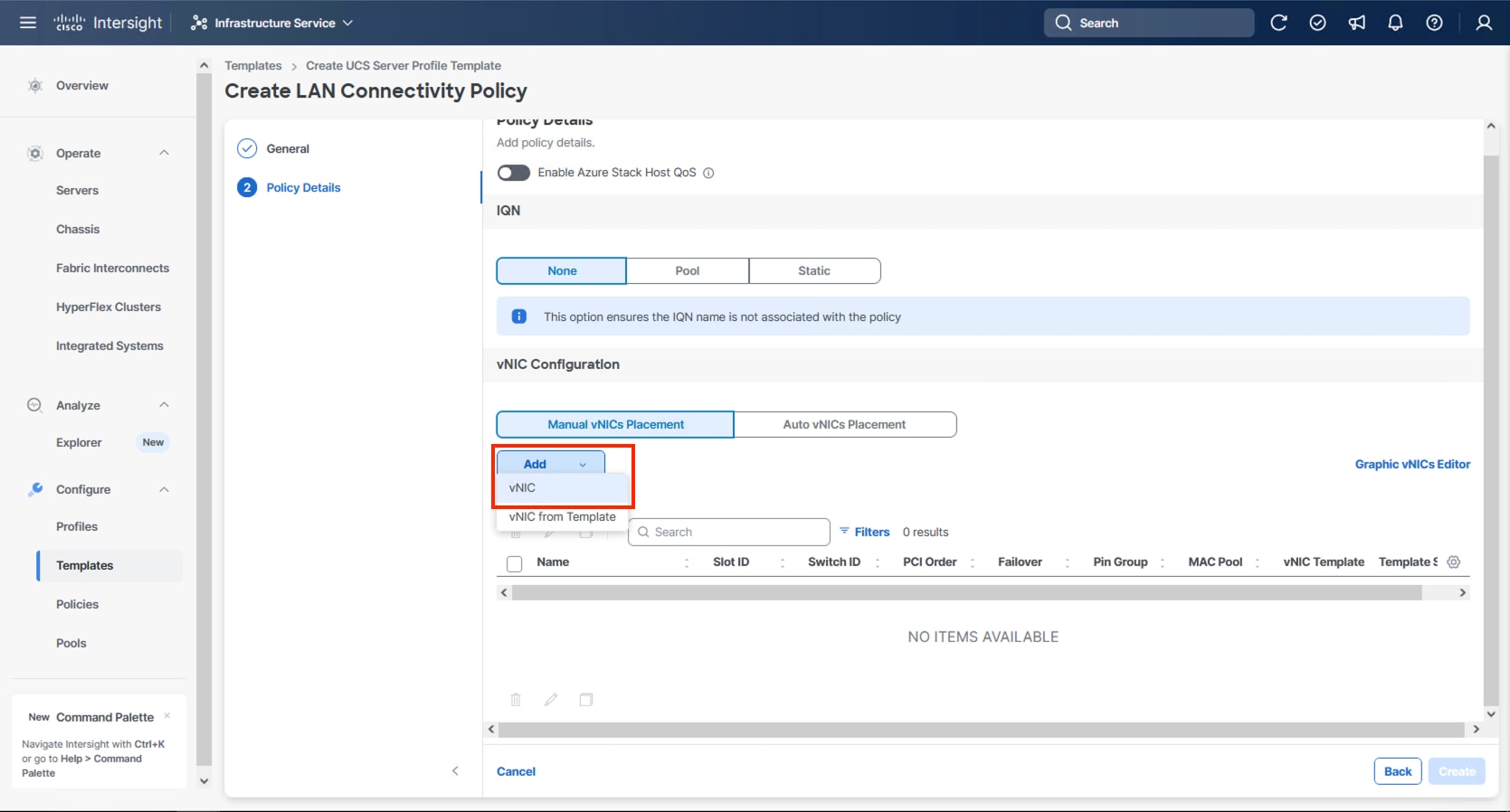
Step 4. Specify the appropriate first vNIC name from Table 11, click Select Pool and click Create New in the pane that appears to the right.
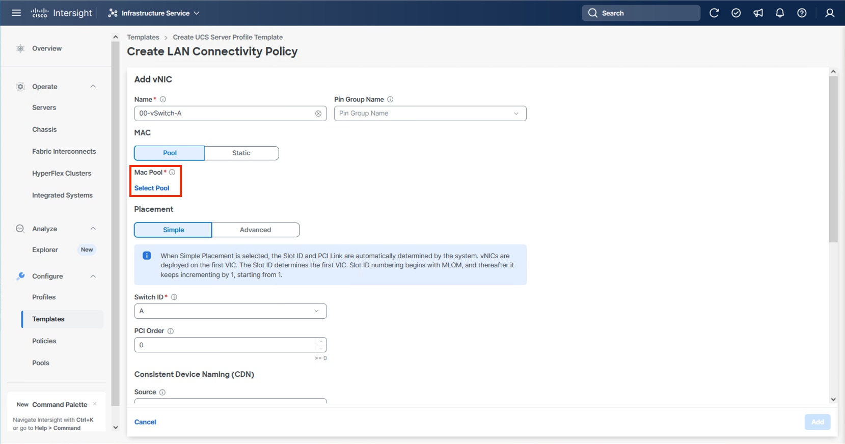
Note: When creating the first vNIC, the MAC address pool has not been defined yet therefore a new MAC address pool will need to be created. Two separate MAC address pools are configured for each fabric. MAC-Pool-A will be reused for all Fabric-A vNICs, and MAC-Pool-B will be reused for all Fabric-B vNICs.
| Pool Name |
Starting MAC Address |
Size |
vNICs |
| MAC-Pool-A |
00:25:B5:24:0A:00 |
256 |
00-vSwitch0-A, 02-VDS0-A, 04-IPStorage-A |
| MAC-Pool-B |
00:25:B5:24:0B:00 |
256 |
01-vSwitch0-B, 03-VDS0-B, 05-IPStorage-B |
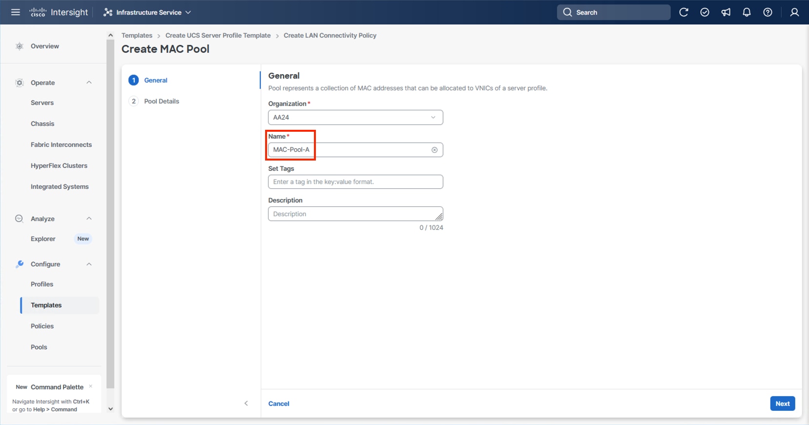
Note: Each server requires 3 MAC addresses from each pool. Adjust the size of the pool according to your requirements.
Step 5. Select the MAC Pool appropriate fabric or click Create New if one has not been created.
Step 6. If creating a new pool, verify that the correct organization is selected from the drop-down list (for example, AA24) and provide a Name for the pool from Table 12 depending on the vNIC being created (for example, MAC-Pool-A for Fabric A).
Step 7. Click Next.
Step 8. Provide the starting MAC address from Table 12 (for example, 00:25:B5:24:0A:00)
Step 9. Provide the size of the MAC address pool from Table 12 (for example, 256).
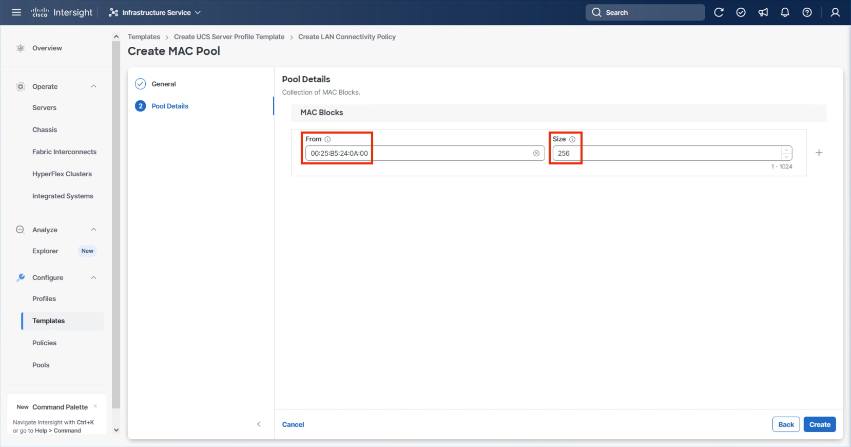
Step 10. Click Create to finish creating the MAC address pool.
Step 11. Confirm the Switch ID and PCI Order values are correct for the vNIC being configured per Table 11.
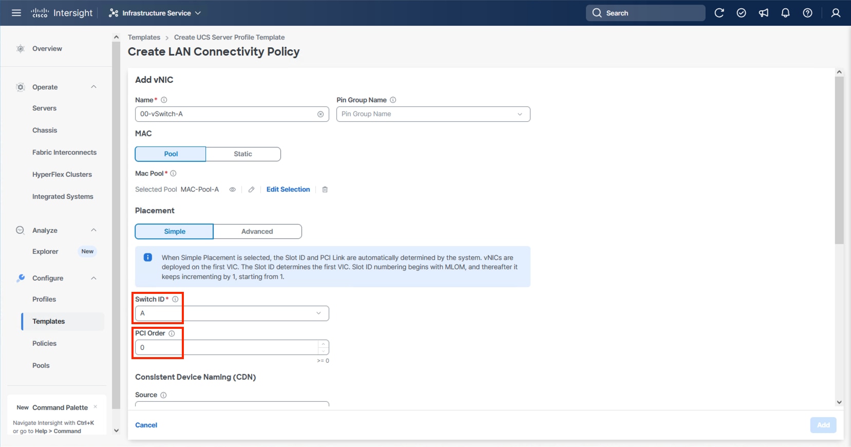
Step 12. Click Select Policy for Ethernet Network Group.
Note: Four Ethernet Network Group policies will be created, one for vSwitch0 vNICs, one for vDS0 vNICs, and one each for the A vs B IPStorage vNICs, detailing the Native VLAN and VLANs that will be carried within the vNICs.
Step 13. When creating the vSwitch0 vNICs and the vSwitch0 Ethernet Network Group Policy is not created, select Create New. Select the appropriate policy if it is created and skip the next six steps.
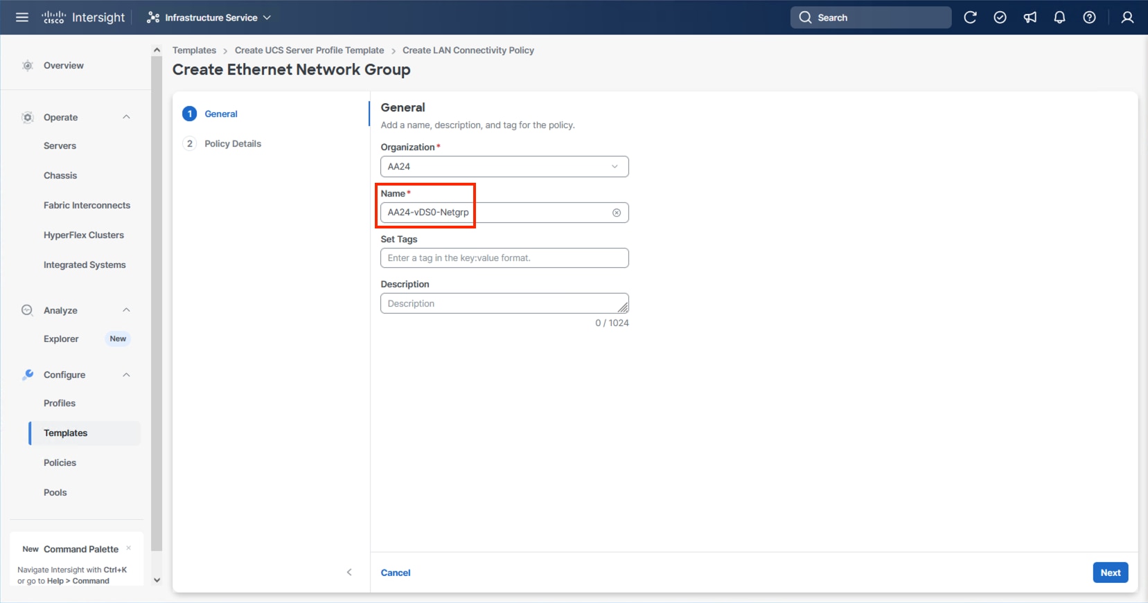
Step 14. Provide a Name for the policy and click Next.

Step 15. Click Add VLANs and select Enter Manually.
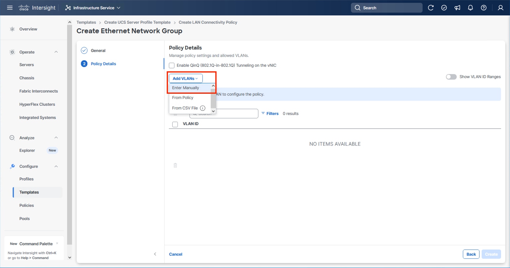
Step 16. Specify the IB-Mgmt VLAN to be used for the ESXi management network and click Enter.
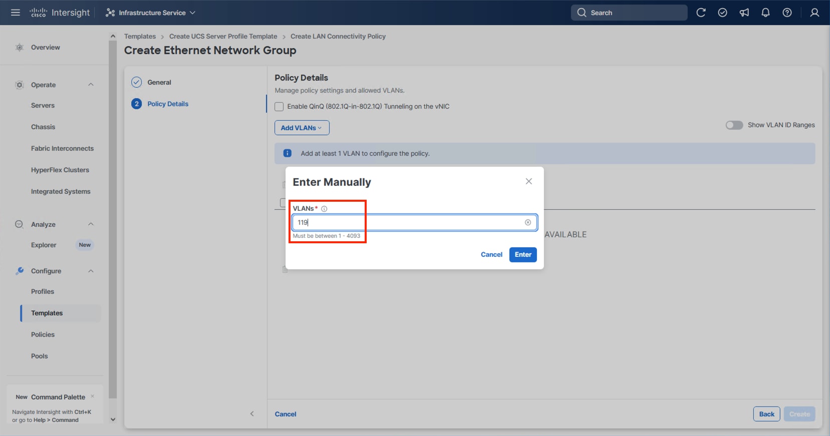
Step 17. Select the entered IB-Mgmt VLAN and click the ellipsis on the right and select Set Native VLAN.
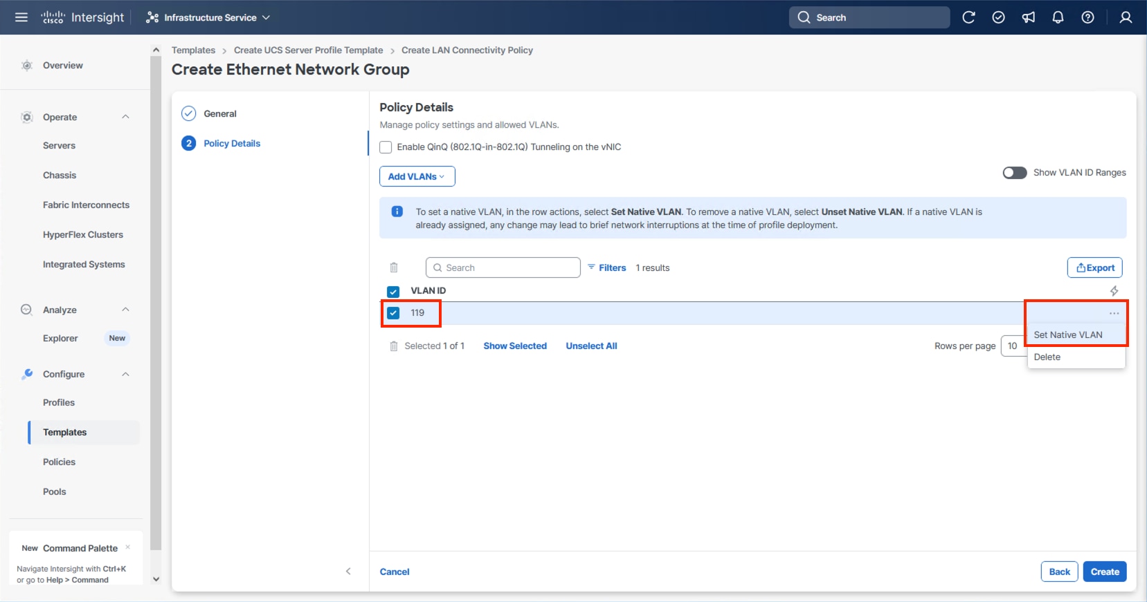
Step 18. Click Create.
Step 19. Select the newly created Ethernet Network Group policy and click Select.
Step 20. When creating the vDS0 vNICs and the vDS0 Ethernet Network Group Policy is not created, click Select Policy under the Ethernet Network Group and select Create New from the right-side pane. Select the appropriate policy if it is created and skip the next five steps.
Step 21. Provide a Name for the policy and click Next.
Step 22. Click Add VLANs and select Enter Manually.
Step 23. Specify the vDS0 appropriate VLANs from Table 11 and click Enter.
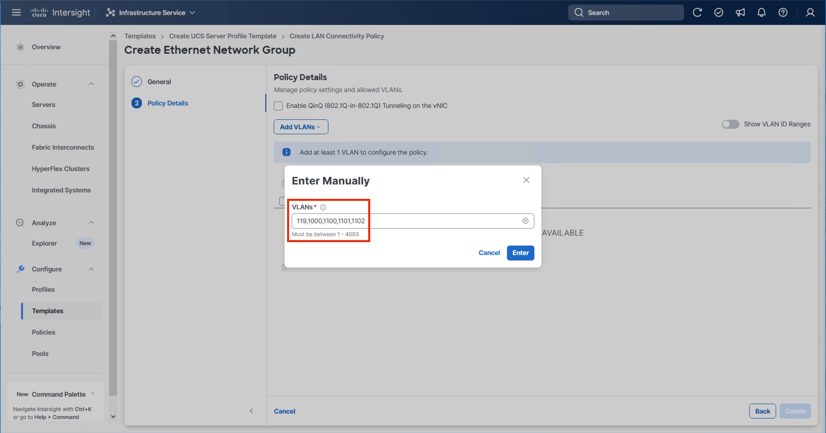
Step 24. Click Create.
Step 25. Select the newly created Ethernet Network Group policy and click Select.
Note: When creating the IPStorage vNICs a distinct Ethernet Network Group Policy is created for each A vs B vNIC. For creating the A fabric side IPStorage vNIC Network Group Policy select Create New. When creating the B fabric side IPStorage vNIC Network Group Policy, follow these steps using the equivalent B side name and values.
Step 26. Provide a Name for the policy and click Next.

Step 27. Click Add VLANs and select Enter Manually.
Step 28. Specify the IPStorage-A appropriate VLANs from Table 11 and click Enter.
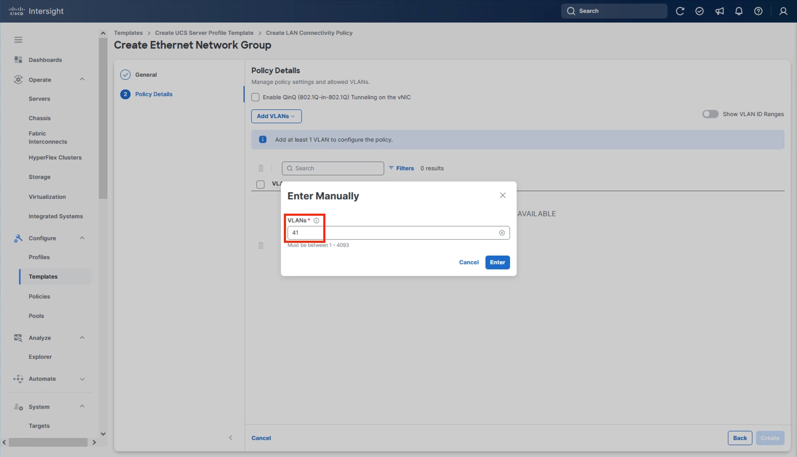
Step 29. Click Create.
Step 30. Select the newly created Ethernet Network Group policy and click Select.
Step 31. For any type of vNIC, click Select Policy under Ethernet Network Control.
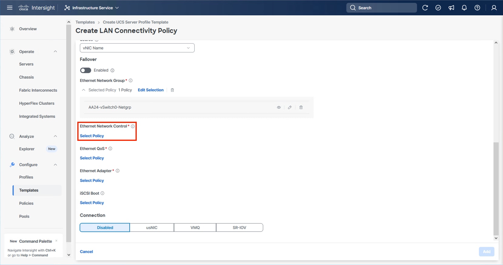
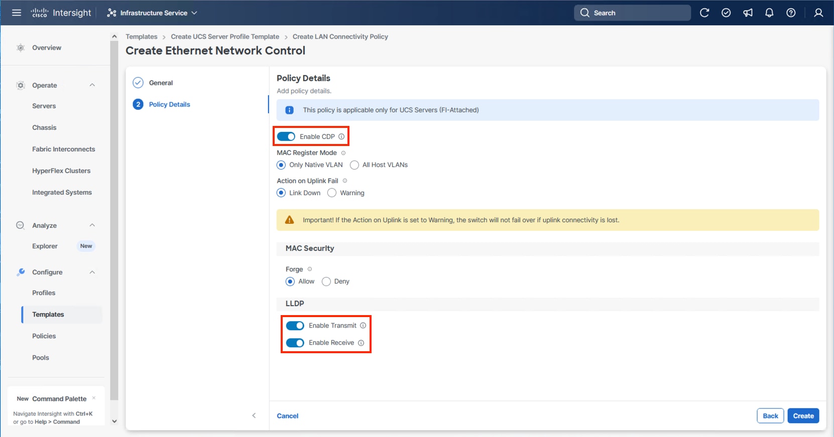
Step 32. Click Create New or select the Ethernet Network Control policy if it has already been created and skip the next two steps.
Step 33. Provide a Name for the policy and click Next.

Step 34. Select Enable CDP, Enable Transmit, and Enable Receive toggles under LLDP and click Create.
Step 35. For any type of vNIC, click Select Policy under Ethernet QoS.
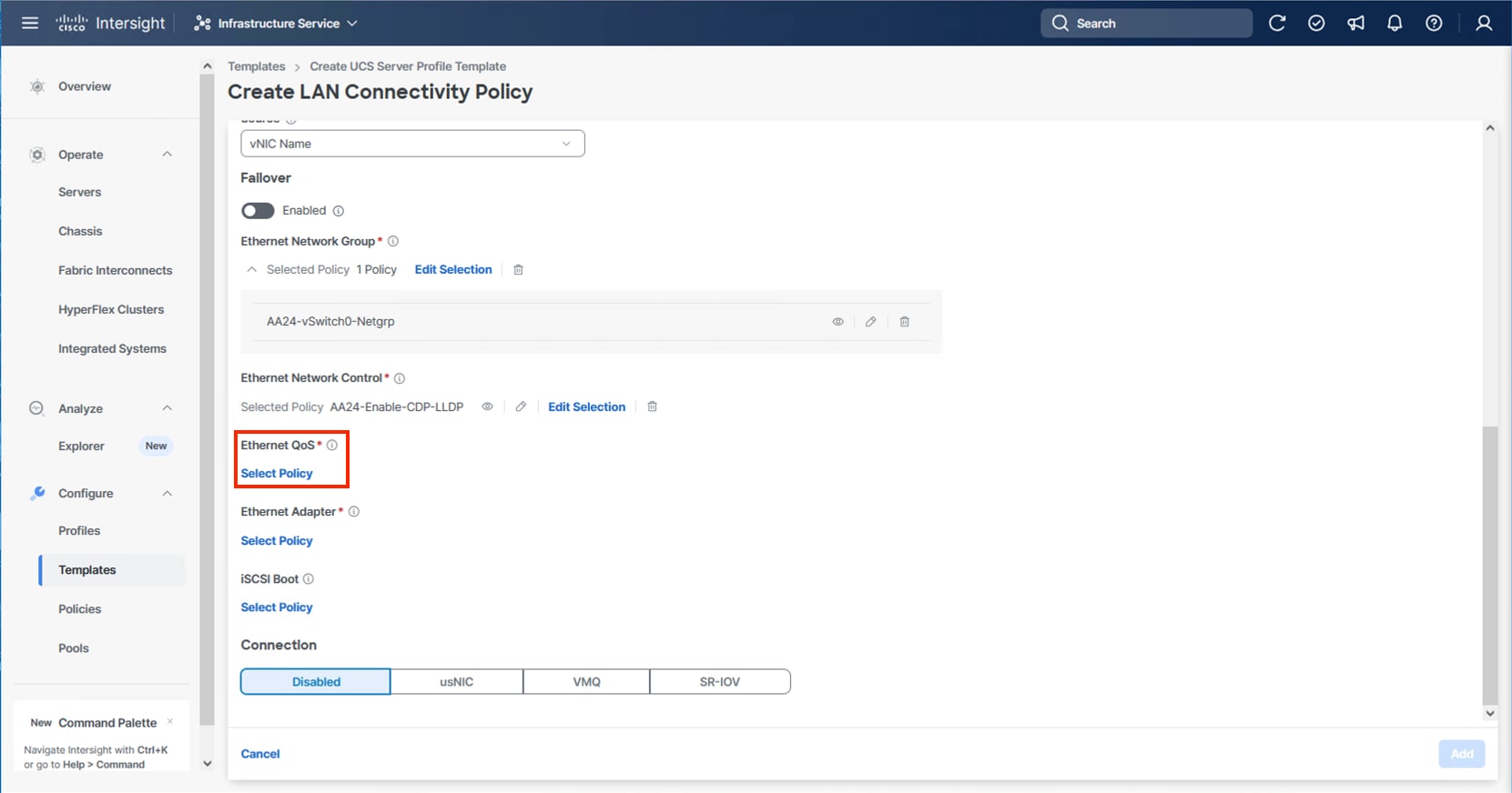
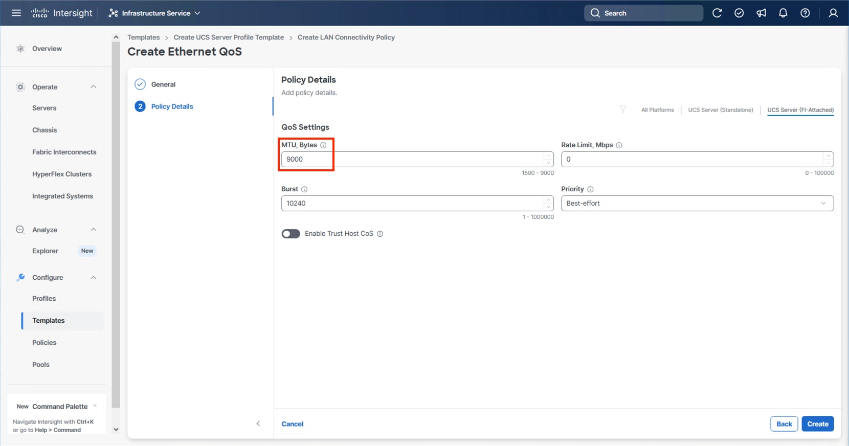
Step 36. Click Create New or select the Ethernet QoS policy if it has already been created and skip the next two steps.
Step 37. Provide a Name for the policy and click Next.
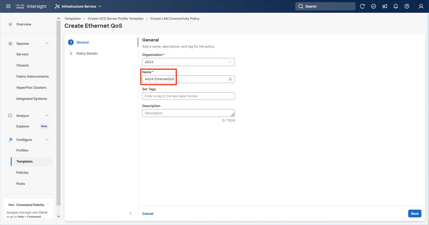
Step 38. Change the MTU, Bytes settings to 9000 and click Create.
Step 39. For any type of vNIC, click Select Policy under Ethernet Adapter.
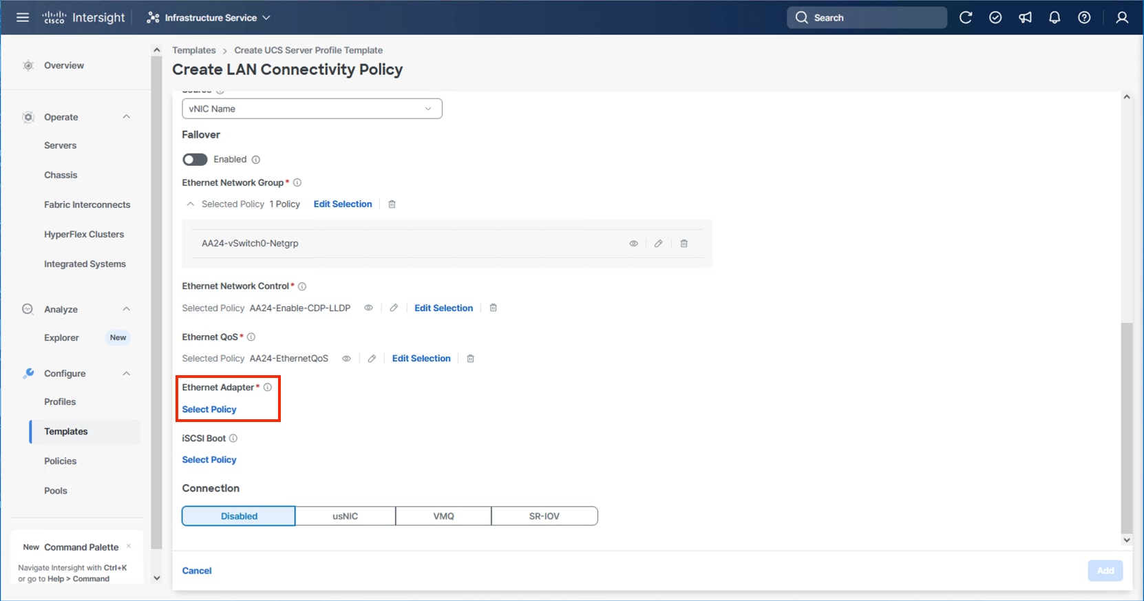
Step 40. Click Create New or select the Ethernet Adapter policy if it has already been created and skip the next three steps. Different policies will be created for the vSwitch0 vNICs and the vDS0 vNICs versus the IPStorage vNICs.
Step 41. To create the vSwitch0 and vDS0 policy, specify a Name for the policy and click Select Cisco Provided Configuration.
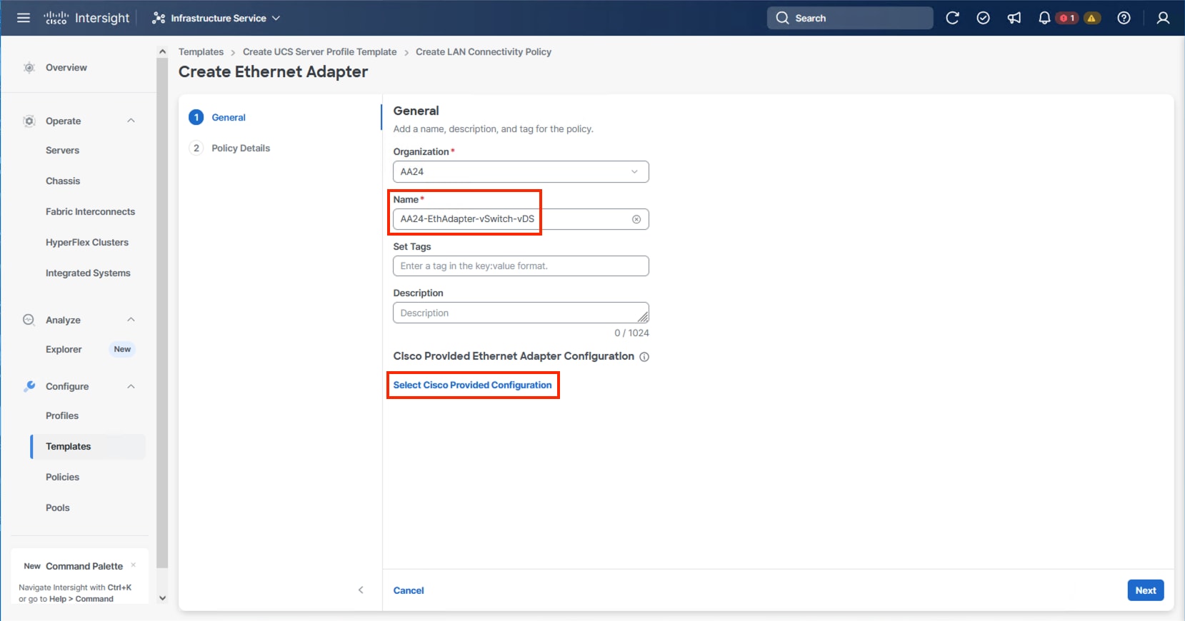
Step 42. Select VMware-v2, click Select and then click Next.
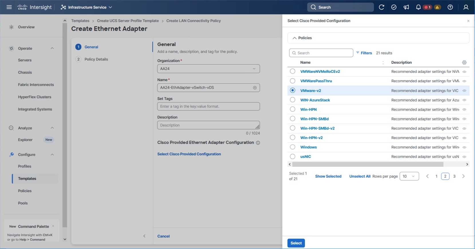
Step 43. Leave all options set to their default settings and click Create.
Step 44. To create the IPStorage Ethernet Adapter policy, specify a Name for the higher traffic settings used in the policy and click Select Cisco Provided Configuration.
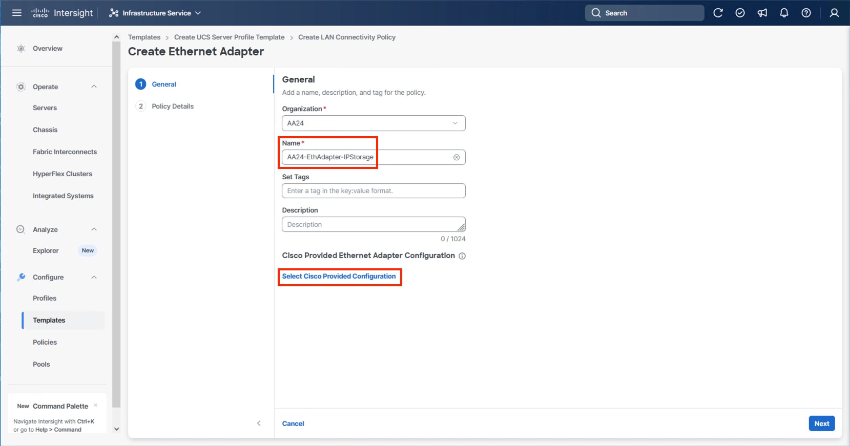
Step 45. Select VMWare-v2 and click Next.
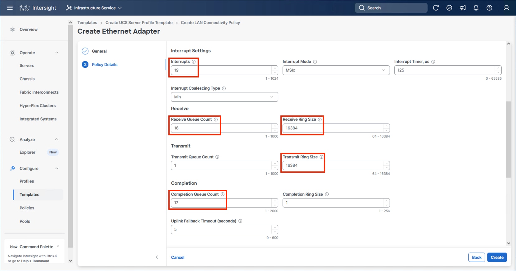
Step 46. Increase Interrupts to 19, the Receive Queue Count to 16, the Receive Ring Size to 16384, the Transmit Ring Size to 16384, and the Completion Queue Count to 17. Click Create.
Step 47. Click Create.
Step 48. Verify the vNIC selections and click Add.
Step 49. Repeat steps 3-48 for each additional vNIC, creating the appropriate pools and policies as required.
Step 50. Click Create to finish the LAN Connectivity Policy.
Step 51. In the IP Storage based topology, a SAN Connectivity Policy will not be needed. Click Next to continue to the Summary.
Procedure 2. Review Summary
Step 1. In the Summary screen, verify that the intended policies are mapped to the appropriate settings.
Cisco UCS IMM Setup Completion
Procedure 1. Derive Server Profiles
Step 1. From the Server profile template Summary screen, click Derive Profiles.
Note: This action can also be performed later by navigating to Templates, clicking “…” next to the template name and selecting Derive Profiles.
Step 2. Under Server Assignment, select Assign Now and select Cisco UCS X215c M8 server(s). You can select one or more servers depending on the number of profiles to be deployed. Optionally, provide a Model filter to exclude additional connected servers as required.
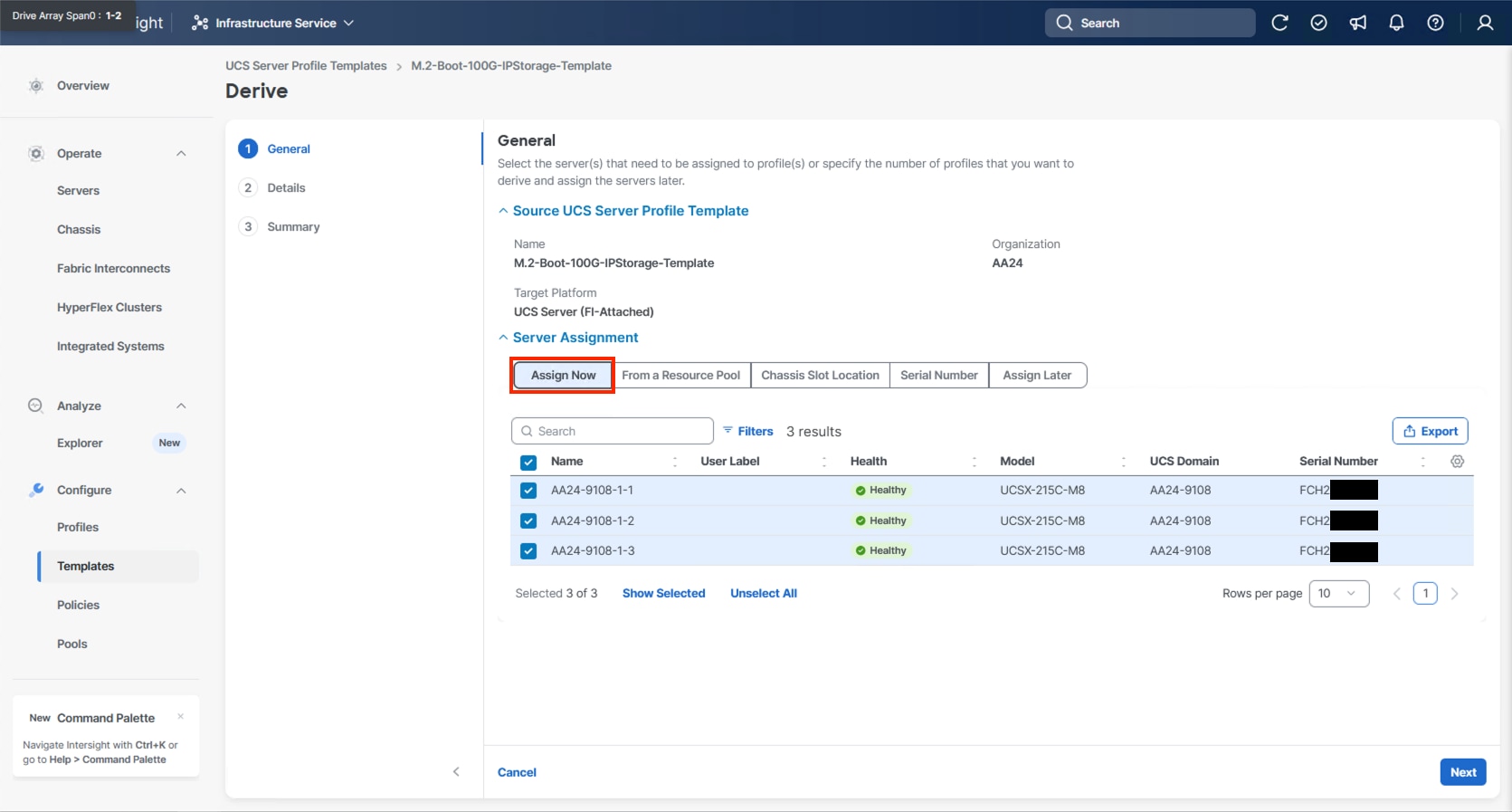
Step 3. Click Next.
Note: Cisco Intersight will fill in the default information for the number of servers selected (3 in this case).
Step 4. Adjust the fields as needed, providing an appropriate Profile Name Prefix.
Note: It is recommended to use the server hostname for the Server Profile name.
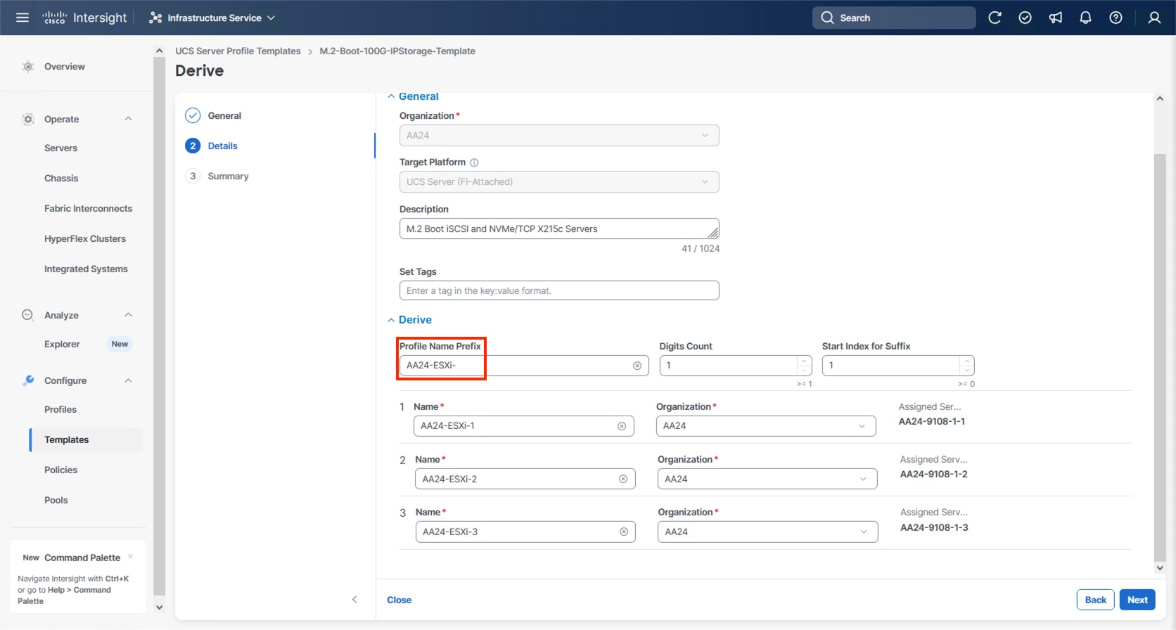
Step 5. Click Next.
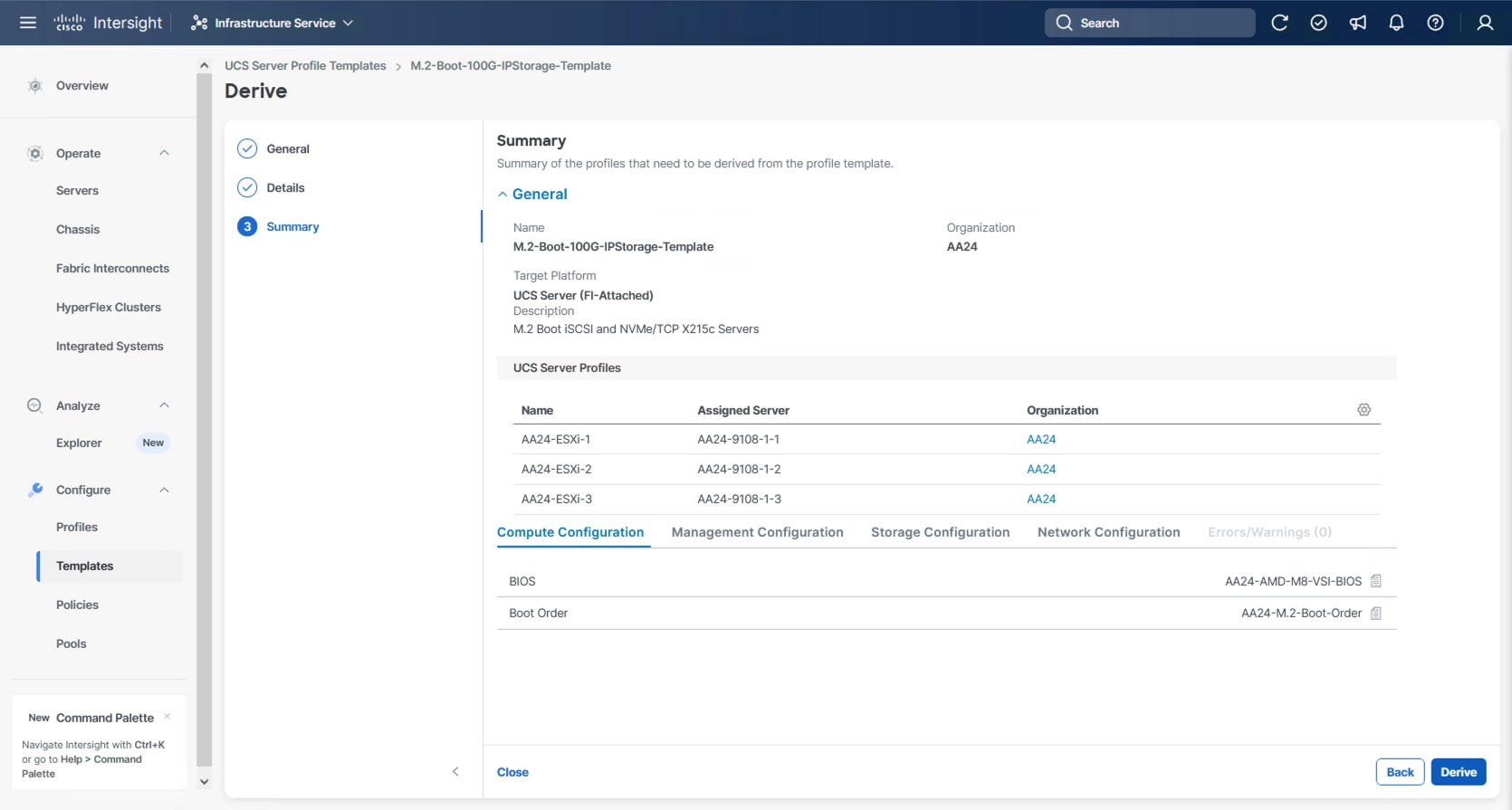
Step 6. Verify the information and click Derive to create the Server Profile(s).
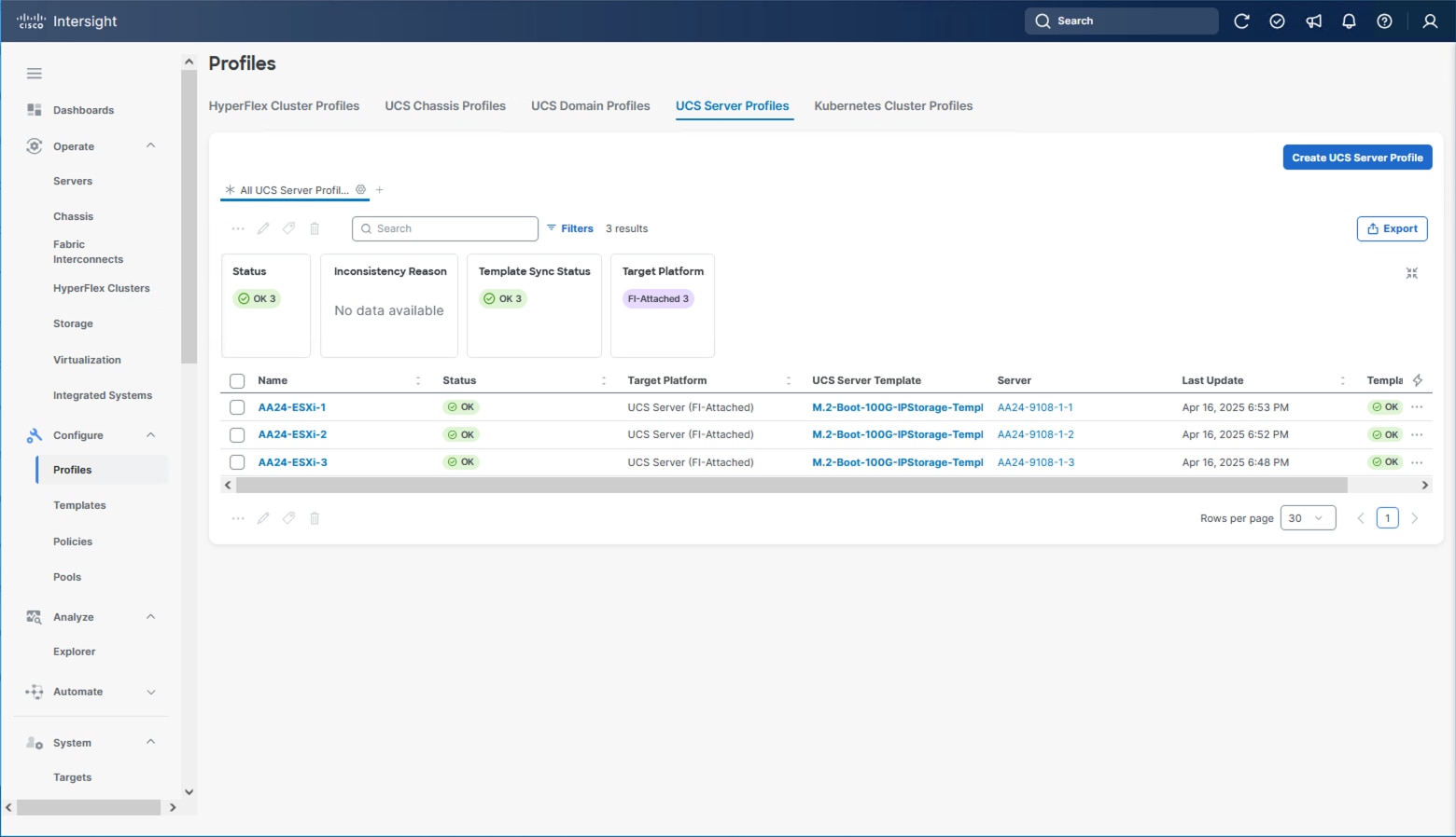
Step 7. Go to Infrastructure Service > Configure > Profiles > UCS Server Profiles list, select the profile(s) just created and click the … at the top of the column and select Deploy. Select Reboot Immediately to Activate and click Deploy.
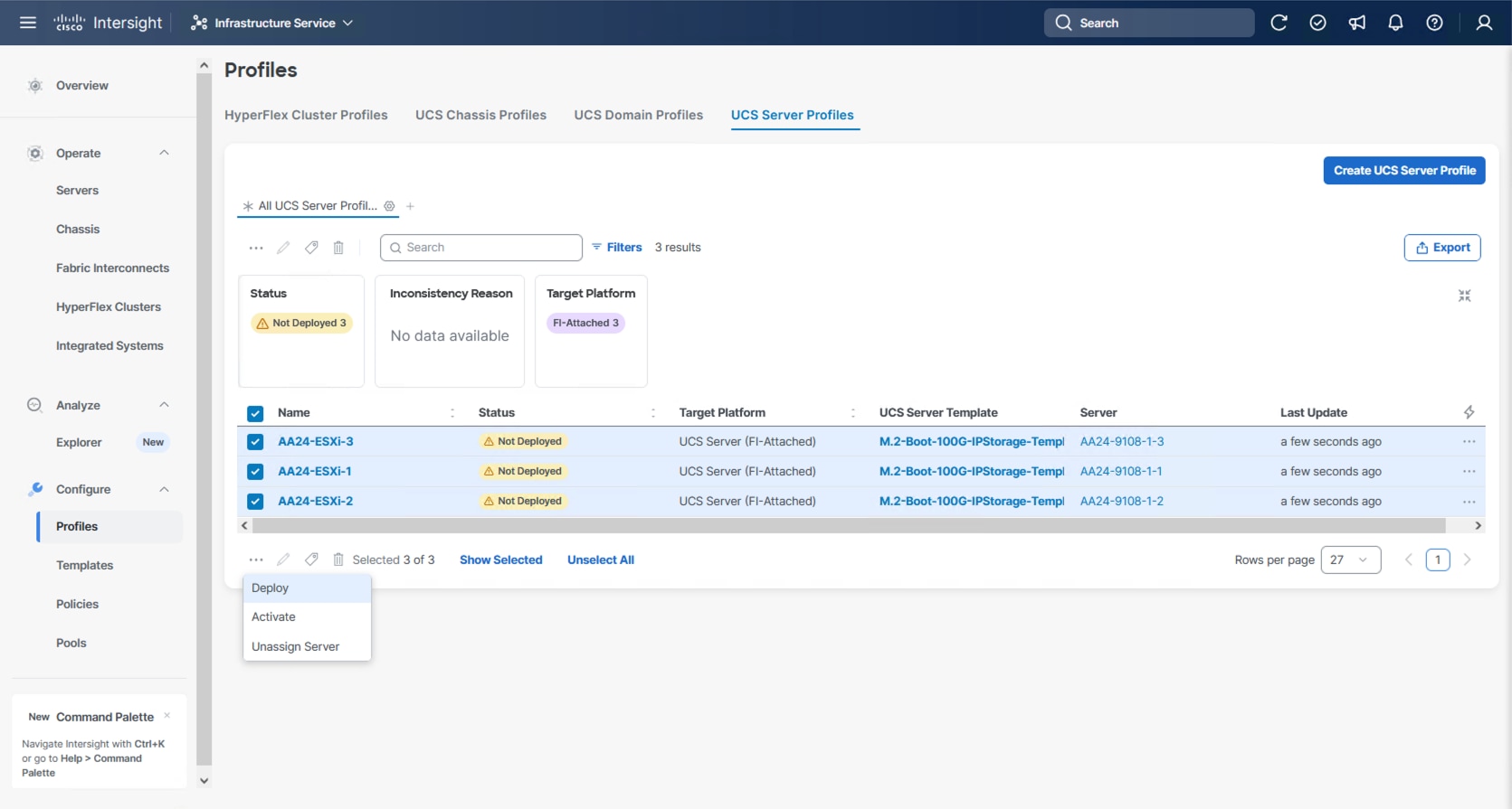
Step 8. Cisco Intersight will start deploying the server profile(s) and will take some time to apply all the policies. Go to the Requests tab to see the progress.
When the Server Profile(s) are deployed successfully, they will appear under the Server Profiles with the status of OK.
Tunneled KVM Setting within System
The additional settings within the System section of Intersight were described in the Create Server Profile Template process to fully enable Tunneled KVM.
Note: If this step has not been performed, complete the following procedure.
Procedure 1. Tunneled KVM Setting
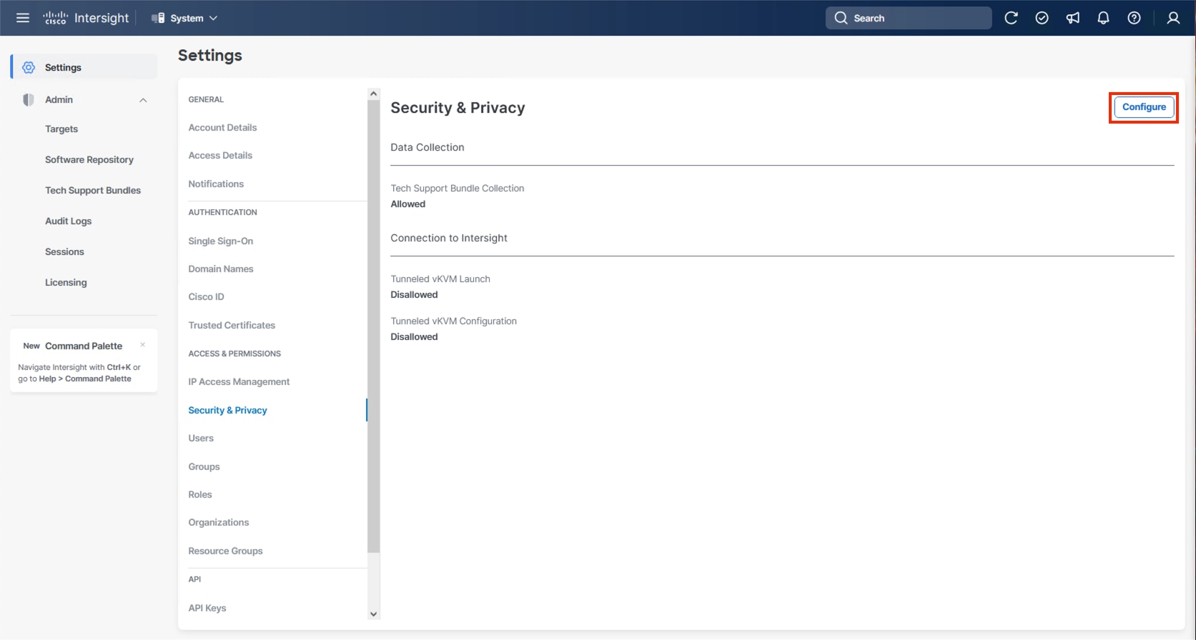
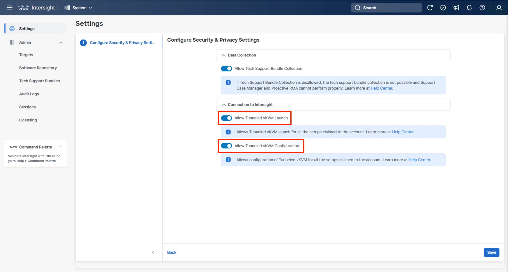
Step 1. Go to System > Settings > Security and Privacy and click Configure.
Step 2. Turn on Allow Tunneled vKVM Launch and Allow Tunneled vKVM Configuration.
Step 3. Click Save to apply the changes.
Hitachi VSP One Block Storage Configuration
This chapter contains the following sections:
● NVMe/TCP Ports on Hitachi VSP One Block
● Hitachi Dynamic Provisioning Pool for LDEVs for UCS Servers
● NVM Subsystem, LDEV, and Host Access
Hitachi VSP One Block NVMe/TCP ports must be configured according to best practices. To access VSP One Block Administrator, you must use the built-in service IP. This service IP can be obtained by contacting your authorized Hitachi Vantara representative.
NVMe/TCP Ports on Hitachi VSP One Block
This section provides the procedure to configure NVMe/TCP ports on Hitachi VSP One Block.
Procedure 1. Configure NVMe/TCP Ports on Hitachi VSP One Block
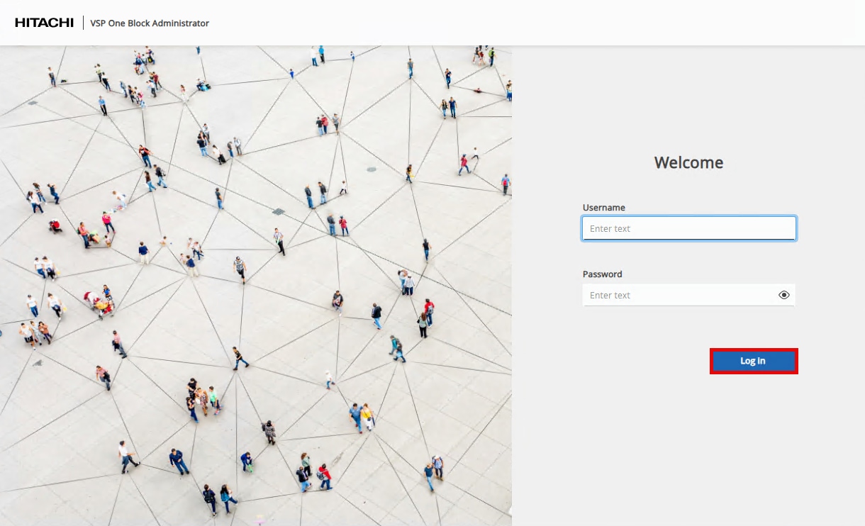
Step 1. Log into VSP One Block Administrator by navigating to the service IP in a web browser. Enter the required credentials and then click Log In.
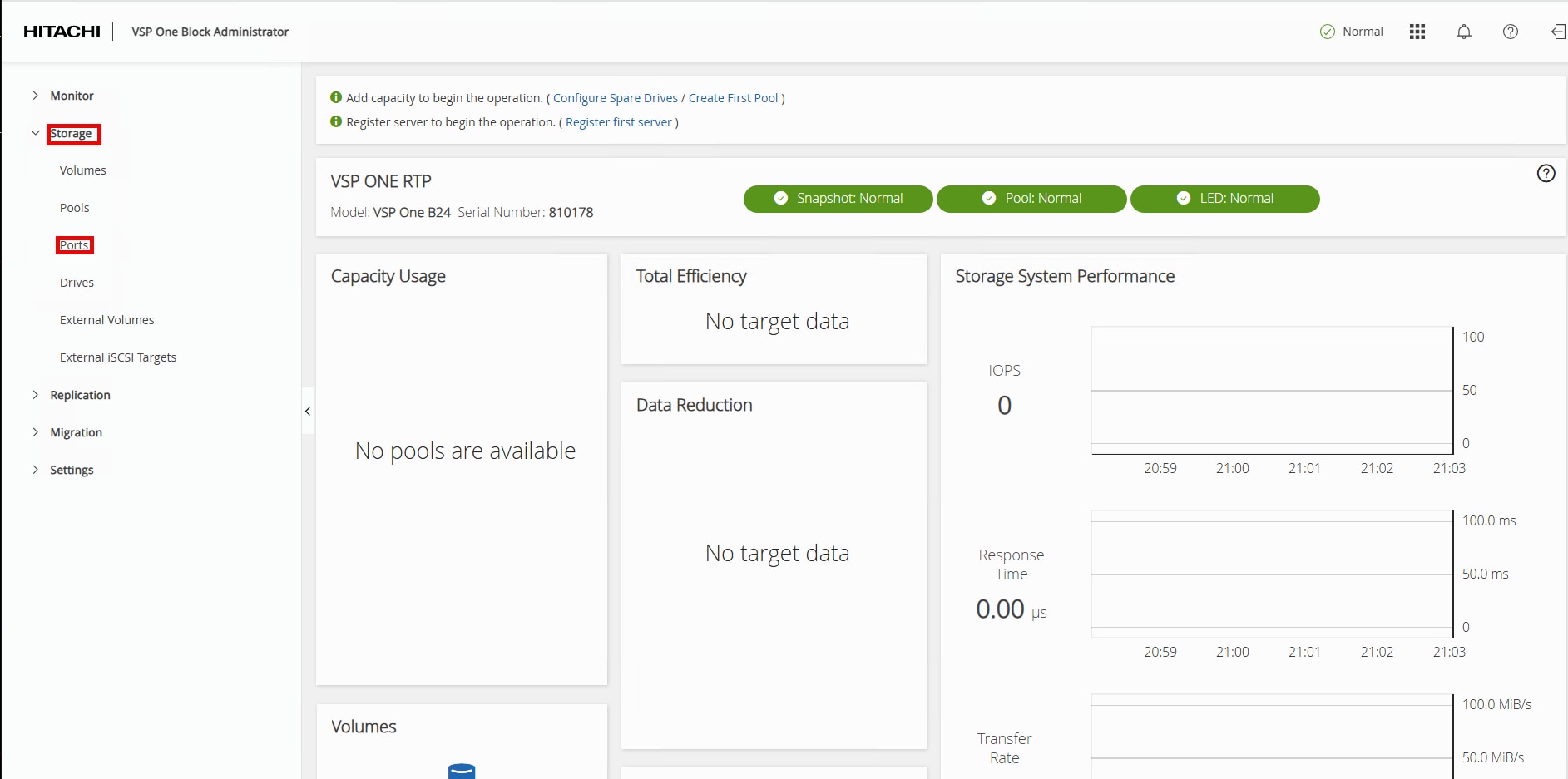
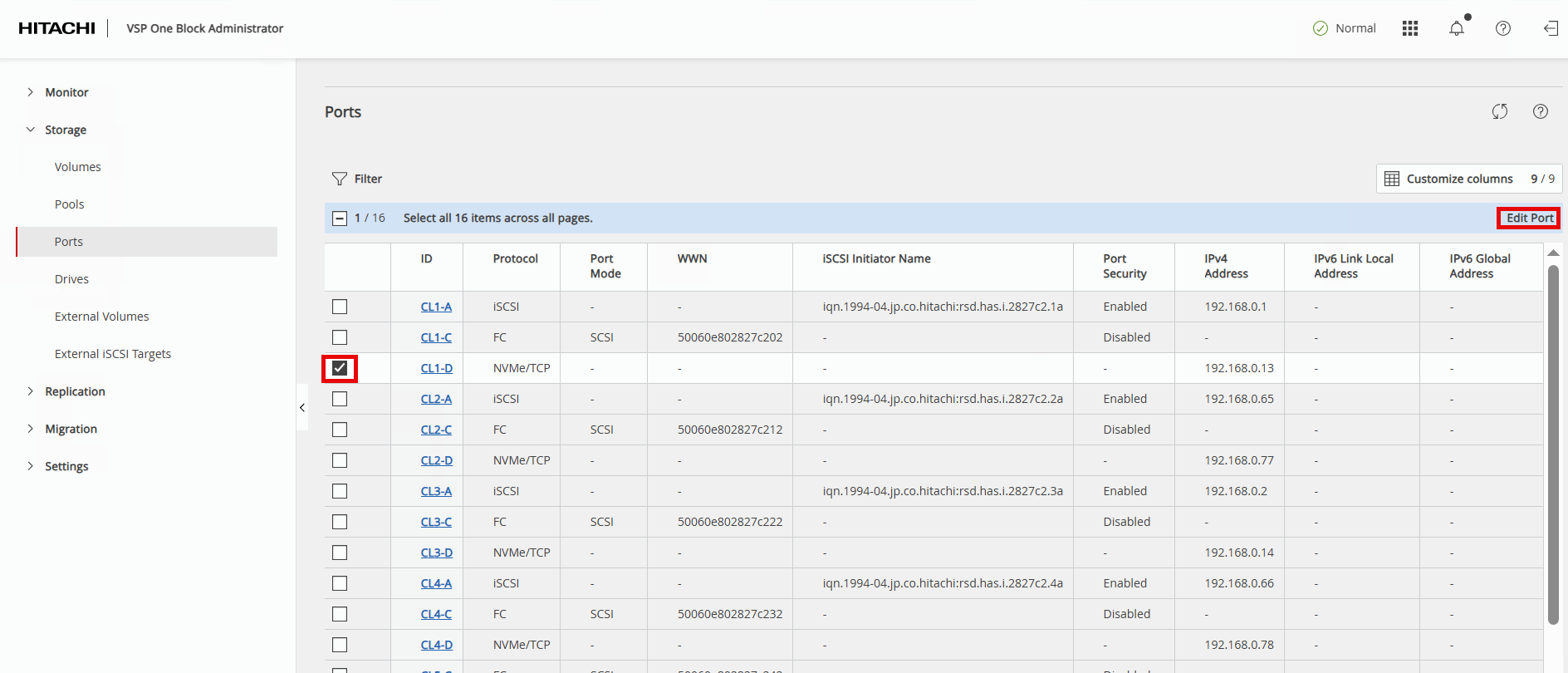
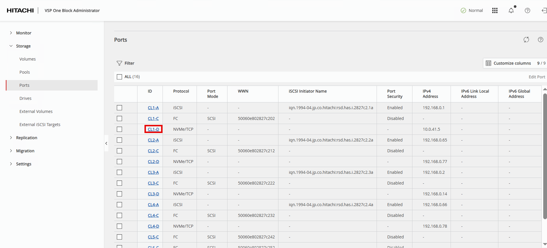
Step 2. In the left navigation pane, expand Storage and click Ports to view the installed storage ports on the storage system.
Step 3. To modify NVMe/TCP ports, select the first NVMe/TCP ID value and click Edit Port in the Actions pane.
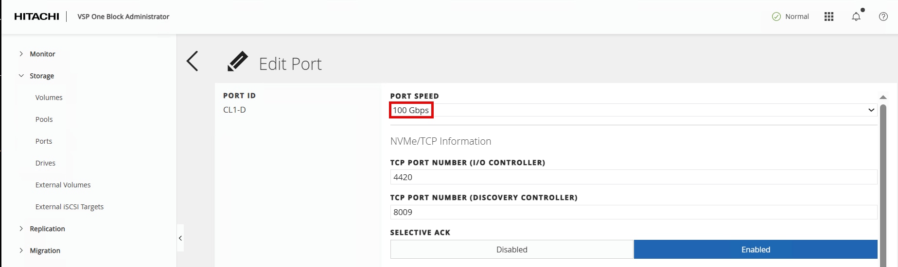
Step 4. In the Edit NVMe/TCP Port dialog box, update the following fields and click Submit.
| Field |
Value |
| PORT SPEED |
keep 100Gbps |
| TCP PORT NUMBER (I/O Controller) |
keep 4420 |
| TCP PORT NUMBER (Discovery Controller) |
keep 8009 |
| SELECTIVE ACK |
keep Enabled |
| DELAYED ACK |
keep Enabled |
| MAXIMUM WINDOW SIZE |
keep 1024 KiB |
| MTU SIZE |
change to 9000 bytes |
| IPV4 ADDRESS |
update based on customer’s network requirements In this validation: Nexus A (CL1-D/CL2-D): Traffic uses VLAN 41 with subsequent IP 10.0.41.x Nexus B (CL3-D/CL4-D): Traffic uses VLAN 42 with subsequent IP 10.0.42.x |
| SUBNET MASK |
update based on customer’s network requirements |
| DEFAULT GATEWAY |
update based on customer’s network requirements |
| IPV6 SETTINGS |
keep Disabled |
| VLAN |
keep Disabled |
Edit Port dialogue continued between screenshots:
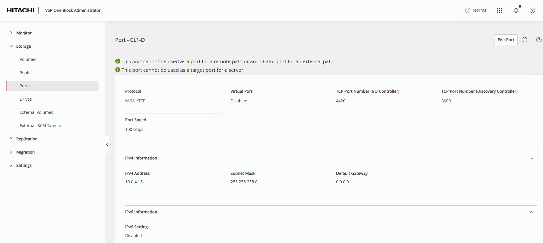
Step 5. The VSP One Block Administrator window will return to the Ports page. Select the port that was just updated to verify the new parameters.
The Ports – CL1-D page will display the updated parameters:
Step 6. Repeat Steps 1 – 6 for all remaining NVMe/TCP ports on the VSP One Block.
Hitachi Dynamic Provisioning Pool for LDEVs for UCS Servers
This section provides the procedure to create a Hitachi Dynamic Provisioning pool for LDEVs for UCS servers.
Procedure 1. Create a Hitachi Dynamic Provisioning Pool for LDEVs for UCS Servers
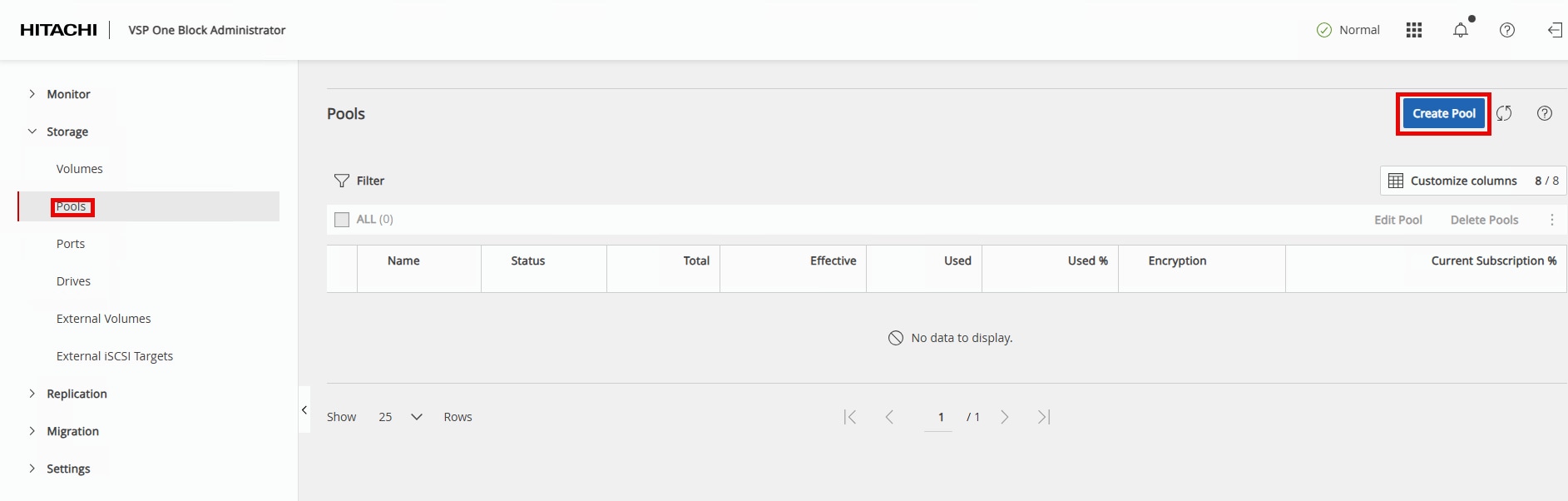
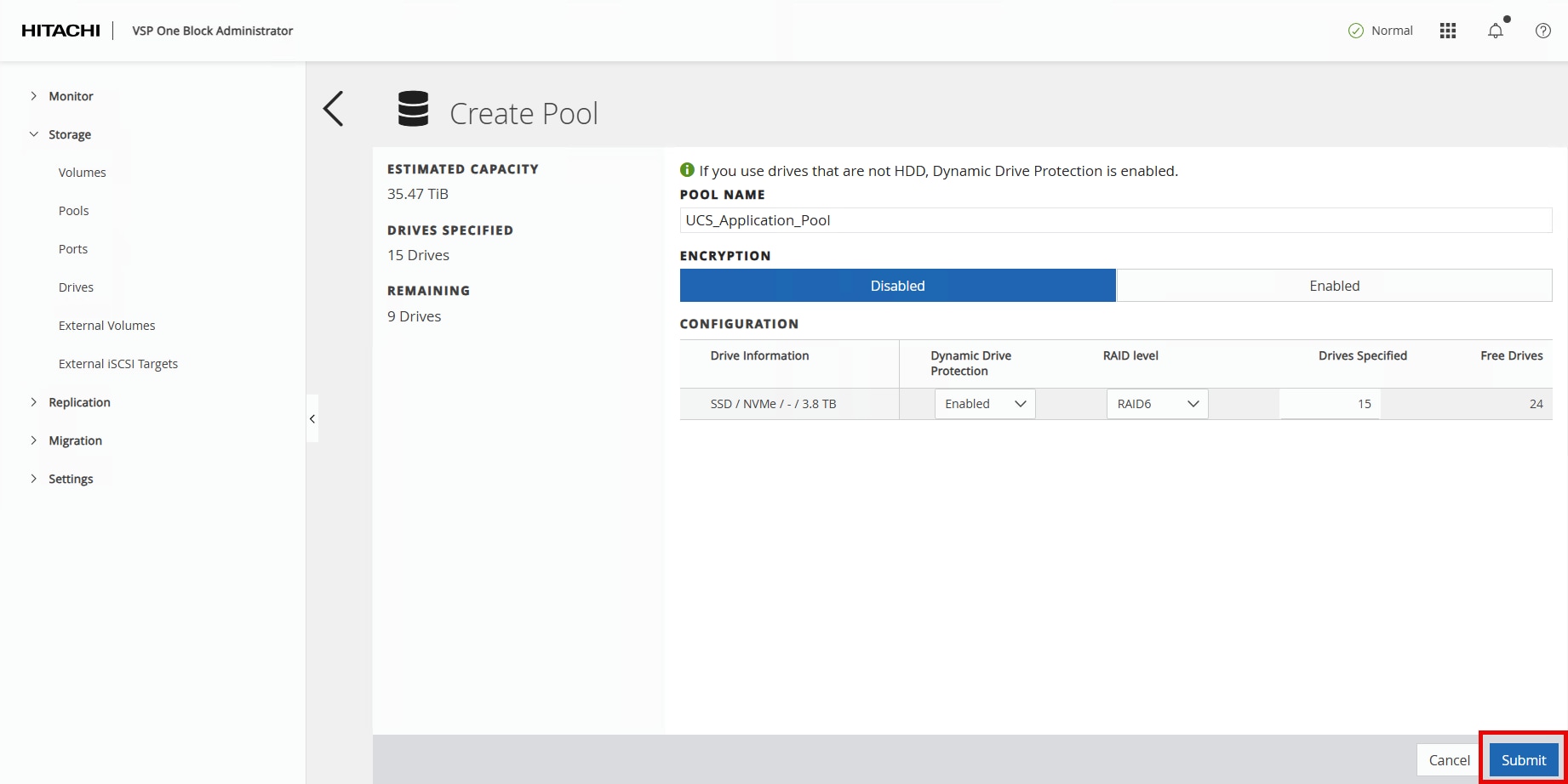
Step 1. In the VSP One Block Administrator window, highlight Pools then click Create Pool.
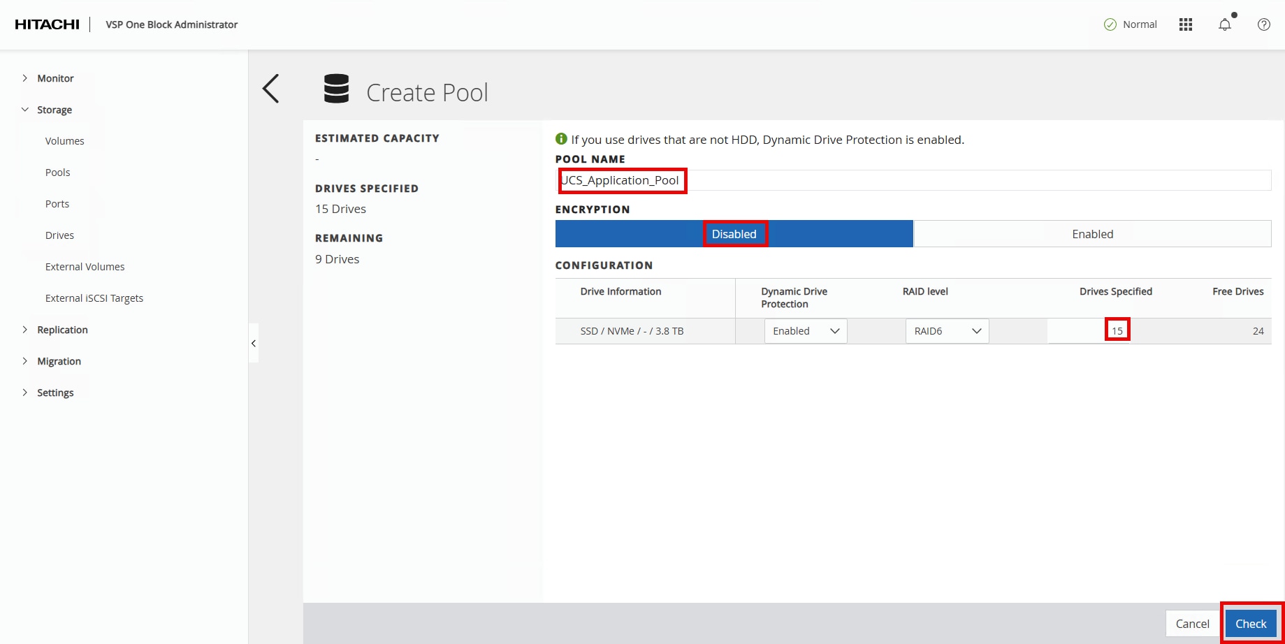
Step 2. Enter the following details in the Create Pool window:
a. POOL NAME: UCS_Application_Pool
b. Encryption: Select Disabled.
c. Drives Specified: Enter 15.
Step 3. Click Check.
Step 4. Click Submit.
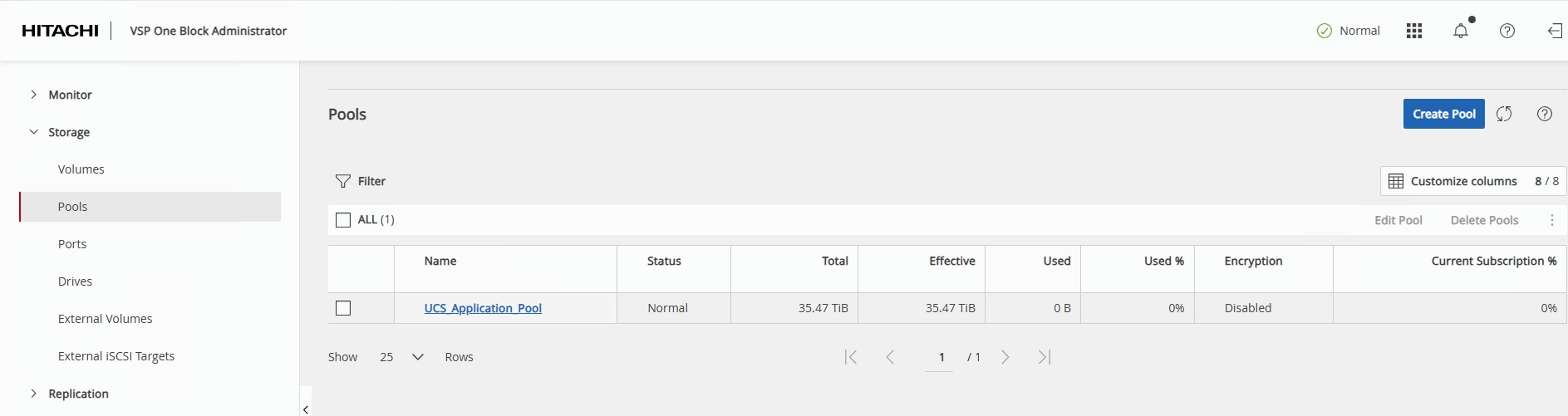
In a few minutes, the new pool creation will be completed.
NVM Subsystem, LDEV, and Host Access
This section provides the procedure to create the NVM Subsystem, LDEV, and enable host access.
Procedure 1. Create the NVM Subsystem and LDEV and enable host access
Step 1. In the current VSP One Block Administrator window, click the Table icon to display the available management tools.
Step 2. Under Management Tools, select Command Console.
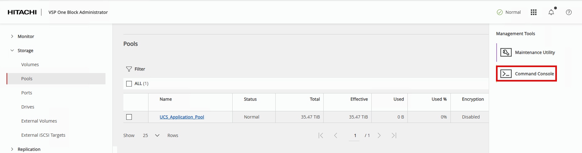
The Command Console opens and is used to configure NVMe/TCP storage using Raidcom commands.
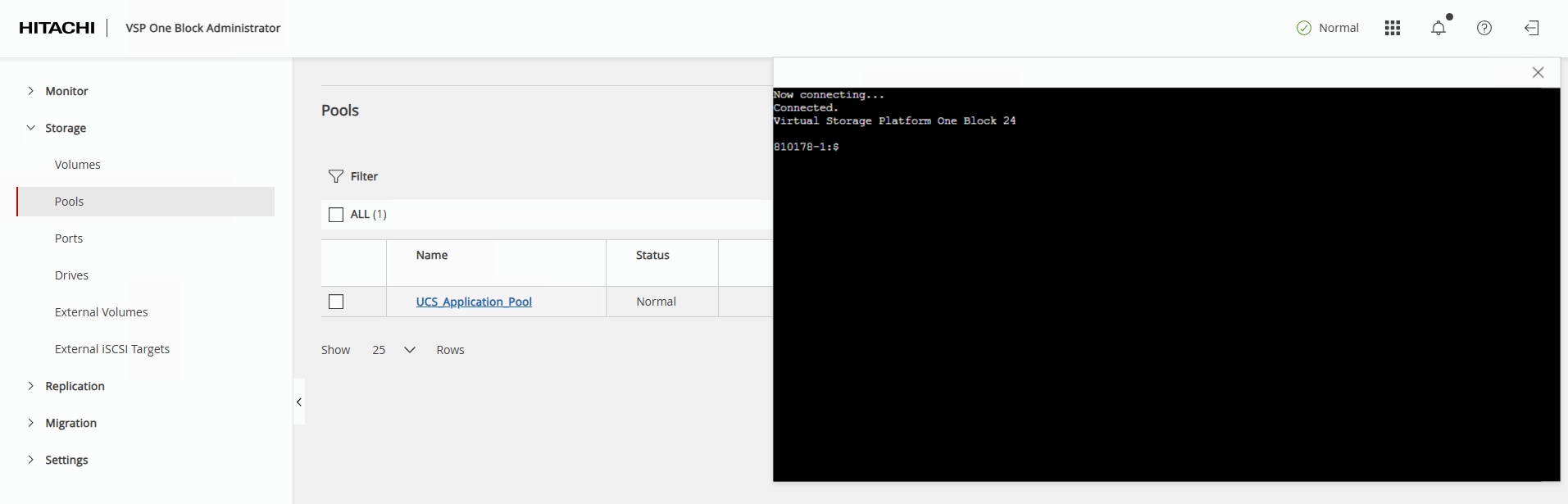
Step 3. Create the NVM Subsystem with ID 10 using the name UCS_NVMe_TCP_VMware and host mode VMWARE_EX with the following command:
raidcom add nvm_subsystem -nvm_subsystem_id 10 -nvm_subsystem_name UCS_NVMe_TCP_VMware -host_mode VMWARE_EX -request_id auto
Step 4. Verify the successful creation of the NVM Subsystem and obtain the new NVM Subsystem NQN with the following command:
raidcom get nvm_subsystem -key opt
Note: The array NVM Subsystem NQN (NVMSS_NQN) is unique for each NVM Subsystems created. ESXi requires the NVM Subsystem NQN to add the array storage controllers.
Example output of NVMSS_NQN:
810178-1:$ raidcom get nvm_subsystem -key opt
NVMSS_ID NVMSS_NAME NVMSS_NQN
10 UCS_NVMe_TCP_VMware nqn.1994-04.jp.co.hitachi:nvme:storage-subsystem-sn.8-10178-nvmssid.00010
Step 5. Register the 100 Gbps NVMe/TCP ports with the NVM Subsystem using the following commands:
raidcom add nvm_subsystem_port -nvm_subsystem_id 10 -port CL1-D -request_id auto
raidcom add nvm_subsystem_port -nvm_subsystem_id 10 -port CL2-D -request_id auto
raidcom add nvm_subsystem_port -nvm_subsystem_id 10 -port CL3-D -request_id auto
raidcom add nvm_subsystem_port -nvm_subsystem_id 10 -port CL4-D -request_id auto
Step 6. Verify the 100 Gbps NVMe/TCP ports have been successfully registered with the NVMe/TCP Subsystem using the following command:
raidcom get nvm_subsystem_port -nvm_subsystem_id 10
Hosts will be added to the nvm_subsystem with a host_nqn value that aligns with the format: nqn.2014.{reverse domain name notation}:nvme:{hostname}. In the validation environment, a DNS domain of adaptive-solutions.local and host names of esxi-[21-23] were used. These values should be adapted to match the target environment.
| Host |
host_nqn |
| esxi-21 |
nqn.2014-08.local.adaptive-solutions:nvme:esxi-21 |
| esxi-22 |
nqn.2014-08.local.adaptive-solutions:nvme:esxi-22 |
| esxi-23 |
nqn.2014-08.local.adaptive-solutions:nvme:esxi-23 |
Step 7. Set the host NQN for the first host to allow access to NVM Subsystem ID 10 using the following command:
raidcom add host_nqn -nvm_subsystem_id 10 -host_nqn nqn.2014-08.local.adaptive-solutions:nvme:esxi-21 \
-request_id auto
Step 8. Verify that the host NQN has been added to the NVM Subsystem ID using the following command:
raidcom get host_nqn -nvm_subsystem_id 10
Step 9. Repeat Steps 7 and 8 for each additional host to be added to the nvm_subsystem.
Note: At this point in the deployment, the ESXi hosts are not installed yet, but can be checked later to confirm the appropriate host_nqn value by logging in to the ESXi host and running the following CLI command: esxcli nvme info get
Step 10. Identify a free LDEV ID and create a new LDEV with capacity savings, deduplication, and compression to create a Data Reduction Shared volume:
raidcom get ldev -ldev_id 0x00010
raidcom add ldev -pool 0 -ldev_id 0x00010 -capacity 1000G -capacity_saving deduplication_compression -drs \
-request_id auto
Step 11. Verify that the new LDEV ID has been created using the following command:
Note: raidcom get ldev -ldev_id 0x00010
Step 12. Assign a name to the newly created LDEV using the following command:
raidcom modify ldev -ldev_id 0x00010 -ldev_name Application_VMFS
Step 13. Verify the name has been added to the LDEV with the following command:
raidcom get ldev -ldev_id 0x00010
Step 14. Create a Namespace for the newly created LDEV by registering them with the NVM Subsystem ID using the following command:
raidcom add namespace -nvm_subsystem_id 10 -ns_id auto -ldev_id 0x00010 -request_id auto
Step 15. Verify that a unique Namespace ID has been created for the LDEV using the following command:
raidcom get namespace -nvm_subsystem_id 10
Step 16. Allow a host to access the LDEV Namespace ID by registering the host NQN to the unique Namespace ID. Set the Host NQN-NameSpace Path using the following Namespace Path command:
raidcom add namespace_path -nvm_subsystem_id 10 -ns_id 1 -host_nqn nqn.2014-08.com.vmware:nvme:esxi-21 -request_id auto
Step 17. Verify the Namespace Path configuration using the following command:
raidcom get namespace_path -nvm_subsystem_id 10
Step 18. Repeat Steps 16 and 17 for any additional ESXi hosts.
Management Tools
This chapter contains the following:
● Cisco Intersight Hardware Compatibility List (HCL) Status
● Deploy Cisco Intersight Assist Appliance
● Claim VMware vCenter using Cisco Intersight Assist Appliance
● Claim Cisco Nexus Switches using Cisco Intersight Assist Appliance
● Claim Hitachi VSP with Cisco Intersight Appliance
Cisco Intersight Hardware Compatibility List (HCL) Status
Cisco Intersight evaluates the compatibility of your UCS system to check if the hardware and software have been tested and validated by Cisco or Cisco partners. Cisco Intersight reports validation issues after checking the compatibility of the server model, processor, firmware, adapters, operating system, and drivers, and displays the compliance status with the Hardware Compatibility List (HCL).
To determine HCL compatibility for VMware ESXi, Cisco Intersight uses Cisco UCS Tools as an installed VIB (vSphere Installation Bundle) which will be installed during the vSphere Cluster image update.
For more information about Cisco UCS Tools manual deployment and troubleshooting, go to: https://intersight.com/help/saas/resources/cisco_ucs_tools
Procedure 1. View Compute Node Hardware Compatibility
Step 1. To find detailed information about the hardware compatibility of a compute node, in Cisco Intersight go to Operate > Servers, click a server, select HCL.
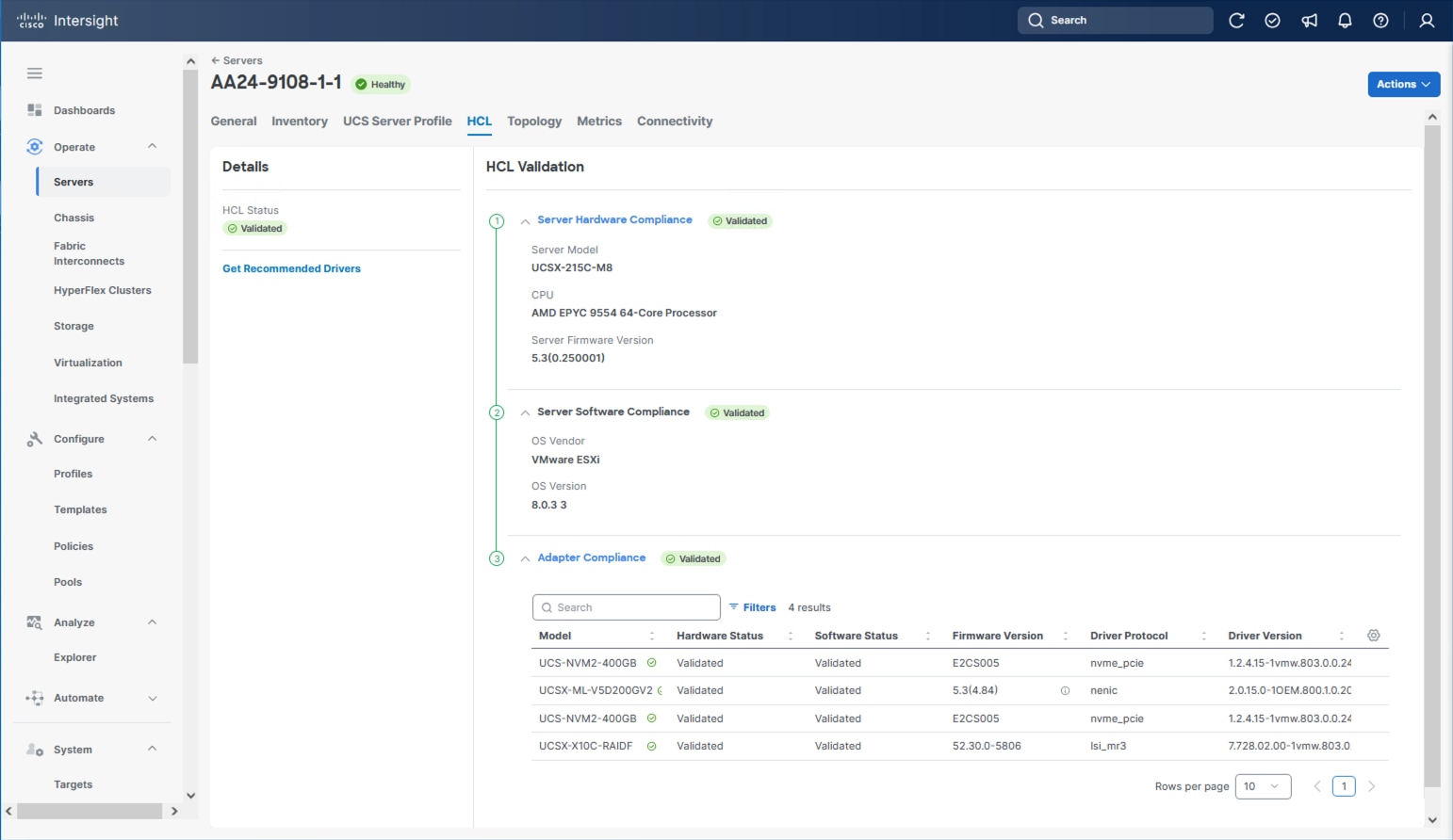
Deploy Cisco Intersight Assist Appliance
Cisco Intersight works with Hitachi VSP and VMware vCenter using third-party device connectors and Cisco Nexus and MDS switches using Cisco device connectors. Since third-party infrastructure and Cisco switches do not contain any usable built-in Intersight device connector, Cisco Intersight Assist virtual appliance enables Cisco Intersight to communicate with these devices.
Note: A single Cisco Intersight Assist virtual appliance can support both the Hitachi VSP storage, VMware vCenter, and Cisco Nexus and MDS switches.
To install Cisco Intersight Assist from an Open Virtual Appliance (OVA), download the latest release of the Cisco Intersight Virtual Appliance for vSphere here: https://software.cisco.com/download/home/286319499/type/286323047/release/1.1.2-0?catid=268439477
Procedure 1. Set up Intersight Assist DNS entries
Setting up Cisco Intersight Virtual Appliance requires an IP address and 2 hostnames for that IP address. The hostnames must be in the following formats:
● myhost.mydomain.com: A hostname in this format is used to access the GUI. This must be defined as an A record and PTR record in DNS. The PTR record is required for reverse lookup of the IP address. If an IP address resolves to multiple hostnames, the first one in the list is used.
● dc-myhost.mydomain.com: The “dc-“ must be prepended to your hostname. This hostname must be defined as the CNAME of myhost.mydomain.com. Hostnames in this format are used internally by the appliance to manage device connections.
In this lab deployment the following example information was used to deploy a Cisco Intersight Assist VM:
● Hostname: as-assist.adaptive-solutions.local
● IP address: 10.1.168.99
● DNS Entries (Windows AD/DNS):
◦ A Record: as-assist.adaptive-solutions.local
◦ CNAME: dc-as-assist.adaptive-solutions.local
For more details, go to https://www.cisco.com/c/en/us/td/docs/unified_computing/Intersight/b_Cisco_Intersight_Appliance_Getting_Started_Guide/b_Cisco_Intersight_Appliance_Install_and_Upgrade_Guide_chapter_00.html.
Procedure 2. Deploy Cisco Intersight OVA
Note: Ensure that the appropriate entries of type A, CNAME, and PTR records exist in the DNS, as explained in the previous section. Log into the vSphere Client and select Hosts and Clusters.
Step 1. From Hosts and Clusters, right-click the cluster and click Deploy OVF Template.
Step 2. Select Local file and click UPLOAD FILES. Browse to and select the intersight-appliance-installer-vsphere-1.0.9-588.ova or the latest release file and click Open. Click NEXT.
Step 3. Name the Intersight Assist VM and select the location. Click NEXT.
Step 4. Select the cluster and click NEXT.
Step 5. Review details, click Ignore, and click NEXT.
Step 6. Select a deployment configuration. If only the Intersight Assist functionality is needed, the default configuration of 16 CPU and 32GB of RAM can be used. Click NEXT.
Step 7. Select the appropriate datastore (for example, VSI-DS-01) for storage and select the Thin Provision virtual disk format. Click NEXT.
Step 8. Select the appropriate management network (for example, IB-MGMT Network) for the OVA. Click NEXT.
Note: The Cisco Intersight Assist VM must be able to access both the IB-MGMT network if holding the vCenter, OOB for connecting to the switches and the VSP One, and intersight.com. Select and configure the management network appropriately. If selecting IB-MGMT network on, make sure the routing and firewall are set up correctly to access the Internet and OOB as needed.
Step 9. Enter all values to customize the template. Click NEXT.
Step 10. Review the deployment information and click FINISH to deploy the appliance.
Step 11. When the OVA deployment is complete, right-click the Intersight Assist VM and click Edit Settings.
Step 12. Expand CPU and verify the socket configuration. For example, in the following deployment, on a 2-socket system, the VM was configured for 16 sockets:
Step 13. Adjust the Cores per Socket so that the number of Sockets matches the server CPU configuration (2 sockets in this deployment):
Step 14. Click OK.
Step 15. Right-click the Intersight Assist VM and go to Power > Power On.
Step 16. When the VM powers on and the login prompt is visible (use remote console), connect to https://intersight-assist-fqdn.
Note: It may take a few minutes for https://intersight-assist-fqdn to respond.
Step 17. Go through the security prompts and select Intersight Assist. Click Start.
Note: If a screen appears prior to the certificate security prompt, the assist may not be ready, and a page refresh may be needed.
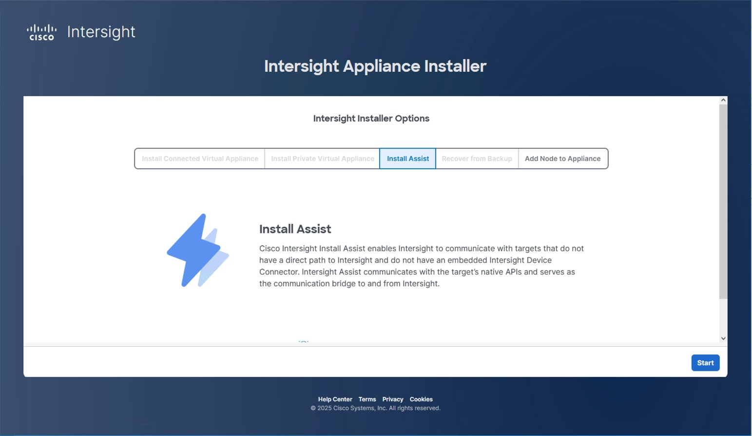
Step 18. Cisco Intersight Assist VM needs to be claimed in Cisco Intersight using the Device ID and Claim Code information visible in the GUI:
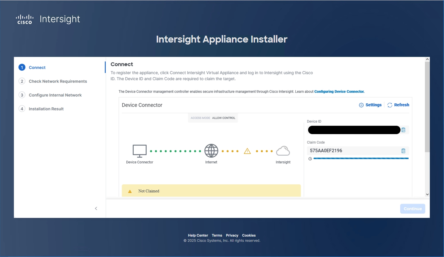
Step 19. Log into Cisco Intersight and connect to the appropriate account.
Step 20. From Cisco Intersight, go to System > Targets.
Step 21. Click Claim a New Target. Filter for Platform Services or find the Cisco Assist option within All. Select Cisco Intersight Assist and click Start.
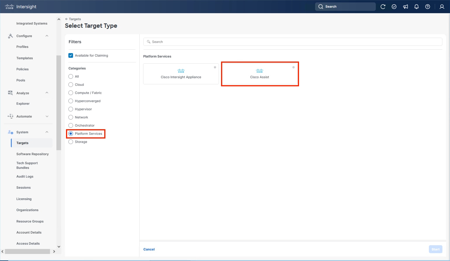
Step 22. Copy and paste the Device ID and Claim Code shown in the Intersight Assist web interface to the Cisco Intersight Device Claim window.
Step 23. Select the Resource Group and click Claim.
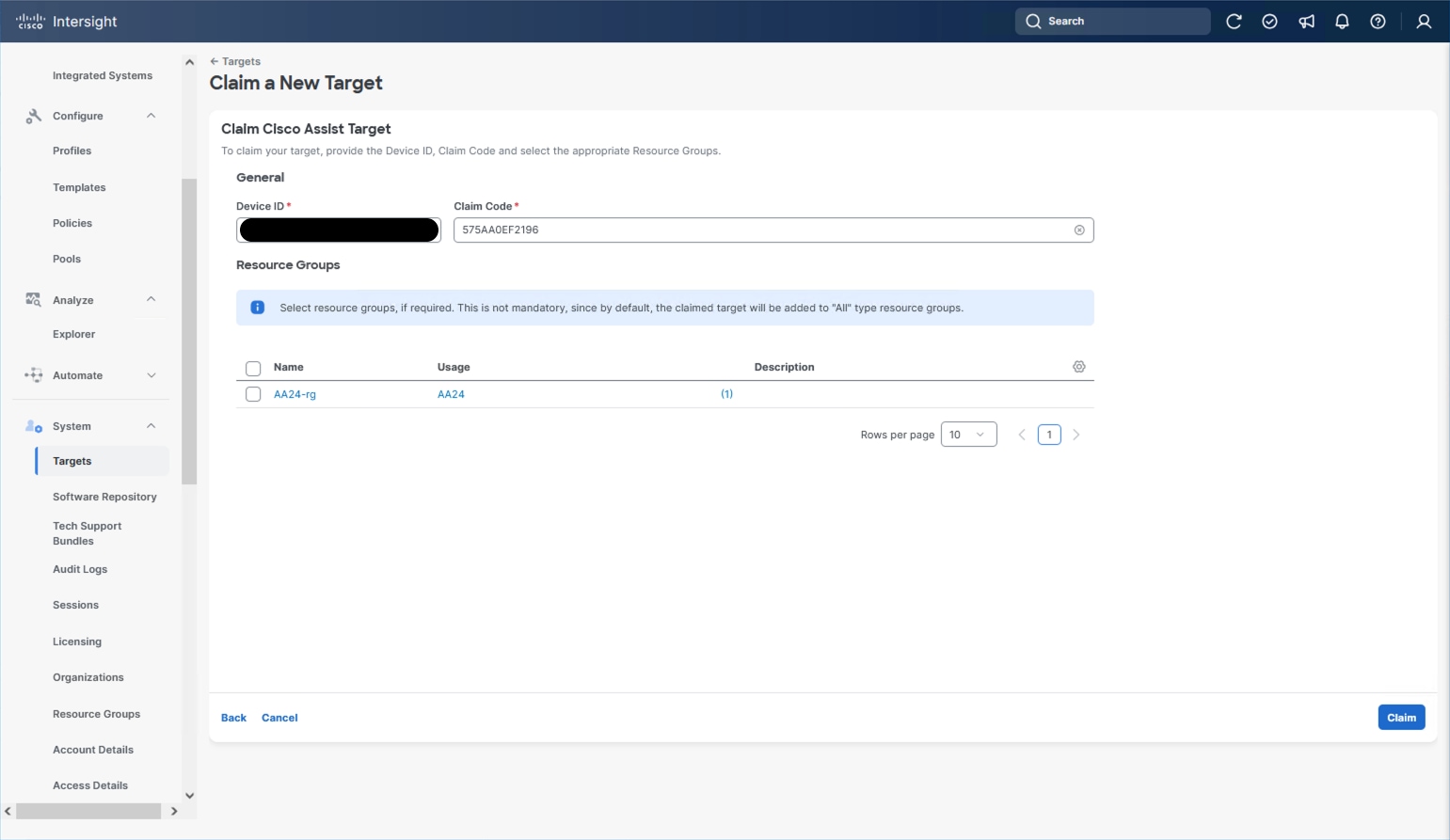
Intersight Assist will now appear as a claimed device.
Step 24. In the Intersight Assist web interface, verify that Intersight Assist is Connected Successfully, and click Continue.
Step 25. Go through the additional network requirement checks and internal network configuration before starting the installation update.
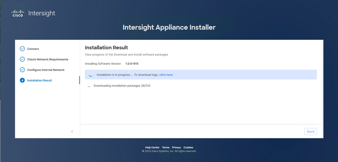
Note: The Cisco Intersight Assist software will be downloaded and installed into the Intersight Assist VM. This can take up to an hour to complete and the Assist VM will be rebooted during this process. It may be necessary to refresh the web browser after the Assist VM has rebooted.
When the software download is complete, an Intersight Assist login screen displays:
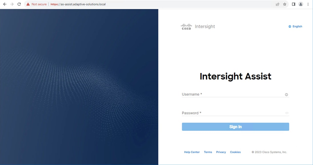
Claim VMware vCenter using Cisco Intersight Assist Appliance
This section contains the procedures to claim VMware vCenter using Cisco Intersight Assist Appliance.
Procedure 1. Claim the vCenter from Cisco Intersight
Step 1. Log into Cisco Intersight and connect to the account registered to Intersight Assist.
Step 2. Go to System > Administration > Targets and click Claim a New Target.
Step 3. Under Select Target Type, filter to Hypervisor, select VMware vCenter under Hypervisor and click Start.
Step 4. In the VMware vCenter window, verify the correct Intersight Assist is selected.
Step 5. Enter the vCenter information. Select Enable Cisco Intersight Plugin for VMware vSphere Client to show Server, Chassis and Fabric Interconnect information within vCenter, also select Enable Hardware Support Manager Plugin to be able to upgrade the IMM server firmware from VMware Lifecycle Manager.
Step 6. Optional, click Enable Datastore Browsing and Enable Guest Metrics for increased visibility and click Claim.
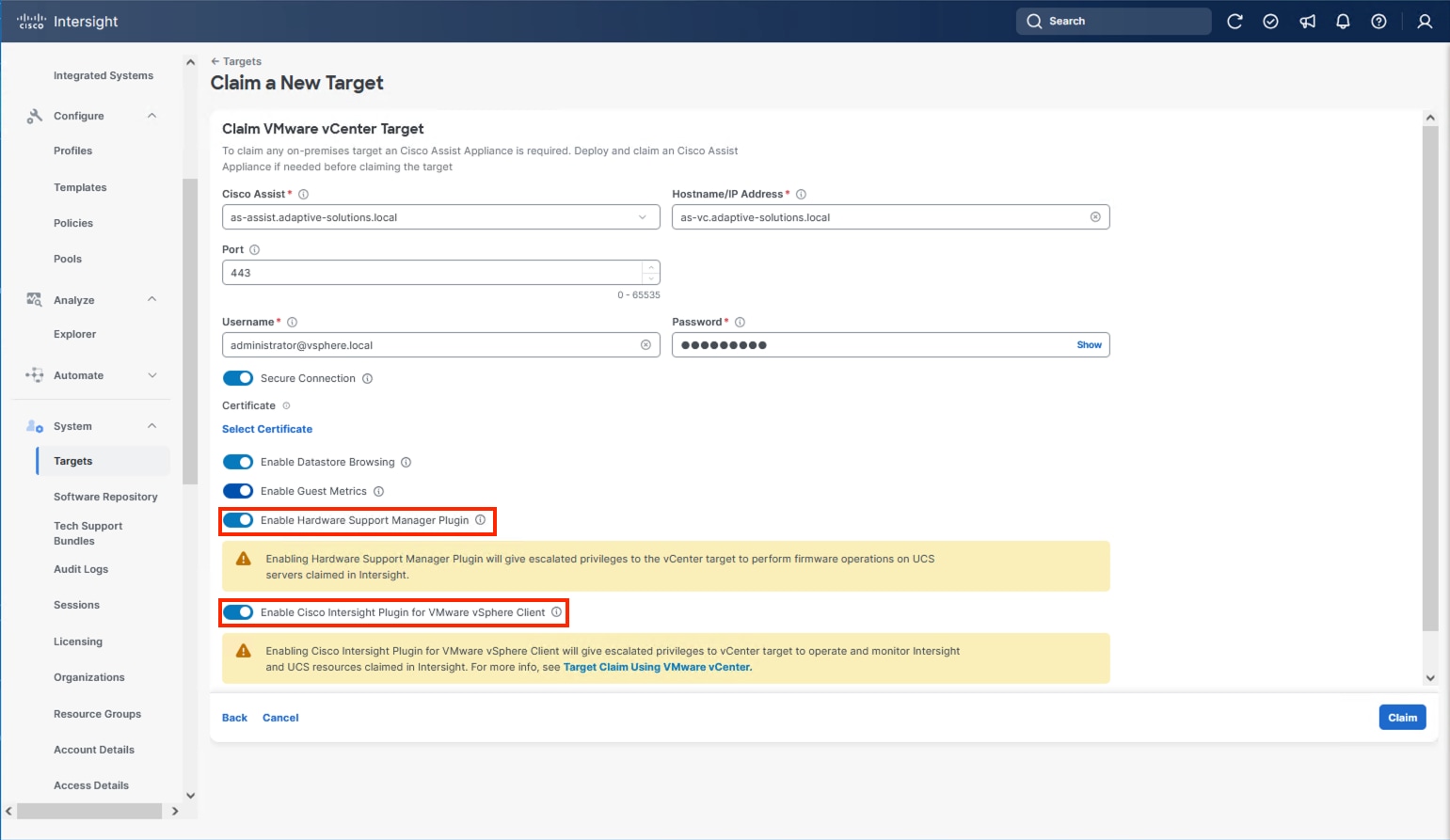
Step 7. After the claim process has completed, you can view the detailed information obtained from the vCenter. Go to Operate > Virtualization and select the Datacenters tab. Other VMware vCenter information can be obtained by navigating through the Virtualization tabs.
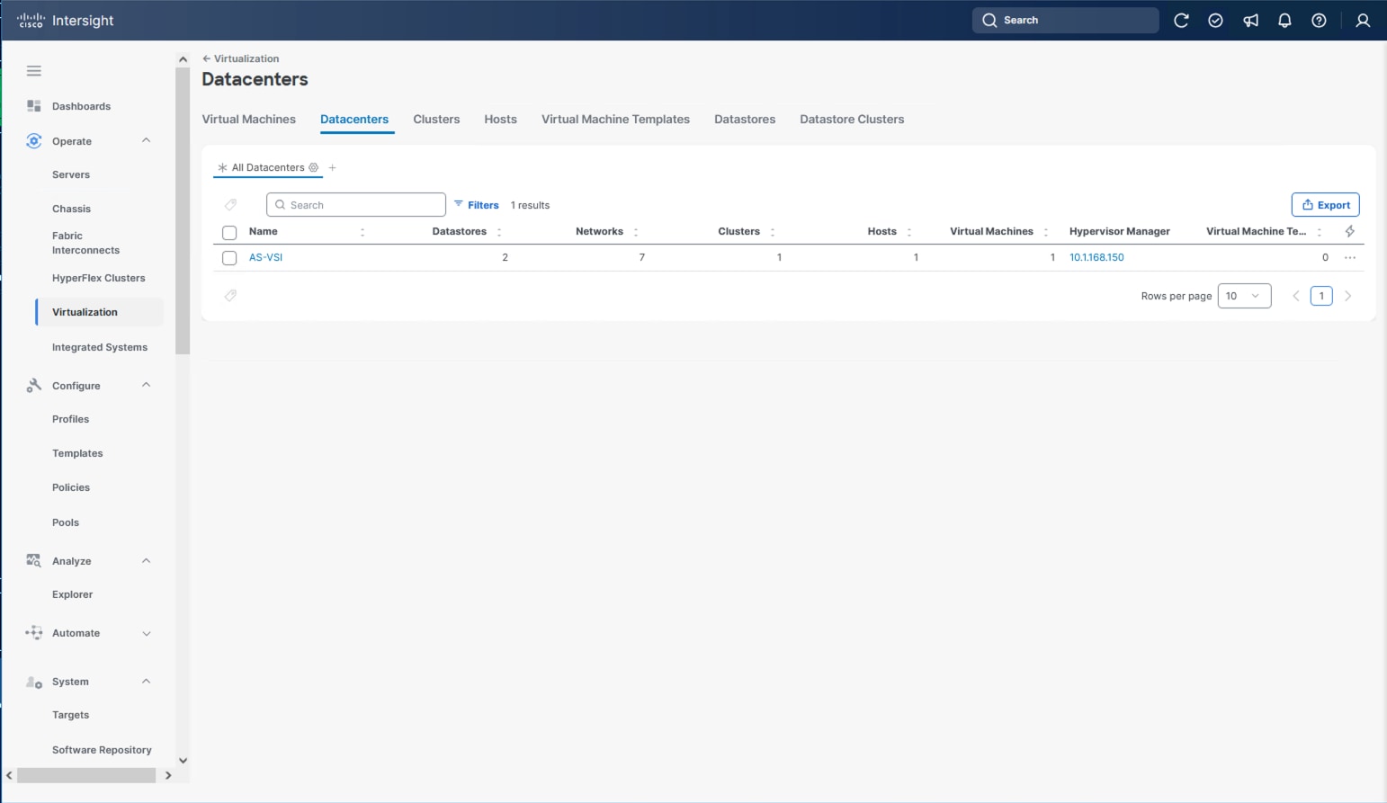
Procedure 2. Interact with Virtual Machines
VMware vCenter integration with Cisco Intersight allows you to directly interact with the virtual machines (VMs) from the Cisco Intersight dashboard. In addition to obtaining in-depth information about a VM, including the operating system, CPU, memory, host name, and IP addresses assigned to the virtual machines, you can use Cisco Intersight to perform the following actions on the virtual machines:
● Start/Resume
● Stop
● Soft Stop
● Suspend
● Reset
● Launch VM Console
Step 1. Log into Cisco Intersight.
Step 2. Go to Operate > Virtualization.
Step 3. Click the Virtual Machines tab.
Step 4. Click “…” to the right of a VM and interact with various VM options.
Step 5. To gather more information about a VM, click a VM name.
Claim Cisco Nexus Switches using Cisco Intersight Assist Appliance
This section provides the procedures to claim Cisco Nexus switches using Cisco Intersight Assist Appliance.
Procedure 1. Claim Cisco Nexus Switches (Optional)
Cisco Intersight can give direct visibility to Nexus switches independent of Cisco Nexus Dashboard Fabric Controller.
Step 1. Log into Cisco Intersight.
Step 2. From Cisco Intersight, go to System > Targets.
Step 3. Click Claim a New Target. In the Select Target Type window, select the Cisco Nexus Switch under Network and click Start.
Step 4. In the Claim Cisco Nexus Switch Target window, click Claim Target with Cisco Assist, and click Leave Page if prompted to switch dialogue windows.
Step 5. Verify the correct Intersight Assist is selected and enter the Cisco Nexus Switch information and click Claim.
Step 6. Repeat Step 1 through Step 5 to add the second Cisco Nexus Switch.
After a few minutes, the two switches will appear under Operate > Networking > Ethernet Switches:
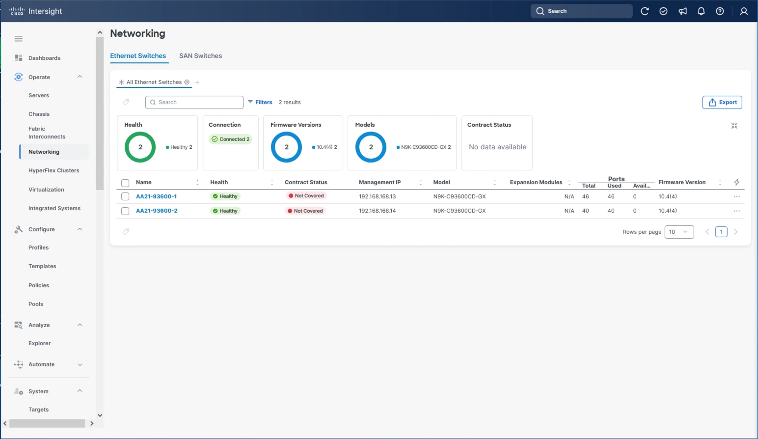
Step 7. Click one of the switch names to get detailed General and Inventory information on the switch.
Claim Hitachi VSP with Cisco Intersight Appliance
Note: Before onboarding the Hitachi VSP One Block to Cisco Intersight, ensure that the prerequisites outlined in the Integrating Hitachi Virtual Storage Platform with Cisco Intersight Quick Start Guide have been completed.
● Begin State
◦ Hitachi Virtual Storage Platform should be online and operational but not claimed by Cisco Intersight.
◦ Intersight Assist VM should be deployed using the Cisco-provided OVA template.
● End State
◦ Cisco Intersight is communicating with Intersight Assist VM.
◦ Hitachi VSP One Block is claimed as a device within Cisco Intersight.
Note: Onboarding a Hitachi VSP One Block only requires using the system’s service IP. The Hitachi Ops Center Configuration Manager REST API server is not required.
Procedure 1. Onboarding Hitachi VSP One Block to Cisco Intersight
Step 1. Log into Cisco Intersight.
Step 2. From the navigation pane, go to System > Targets and click Claim a New Target.
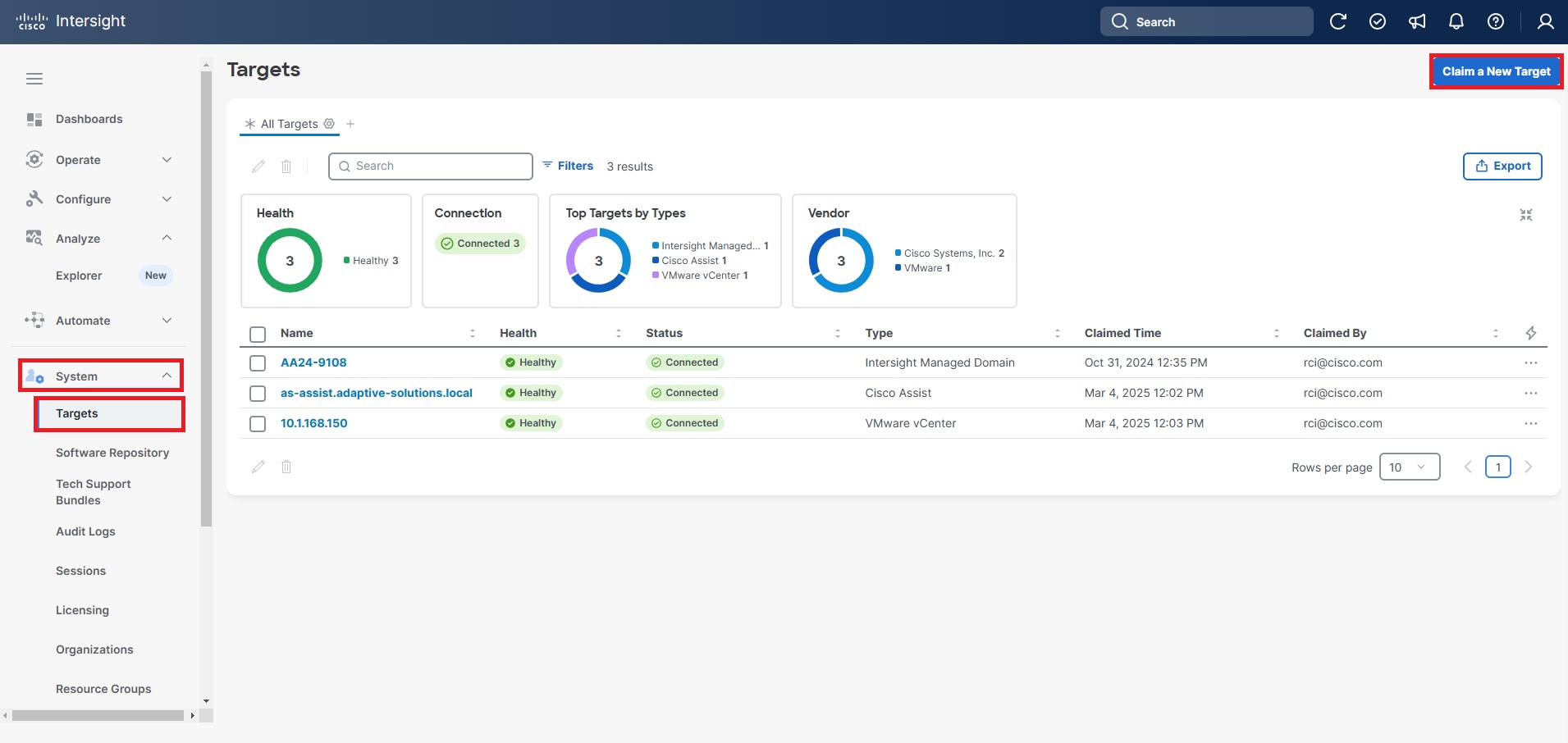
Step 3. From the Categories list, select Storage as the Target Type and select Hitachi Virtual Storage Platform.
Step 4. Click Start.
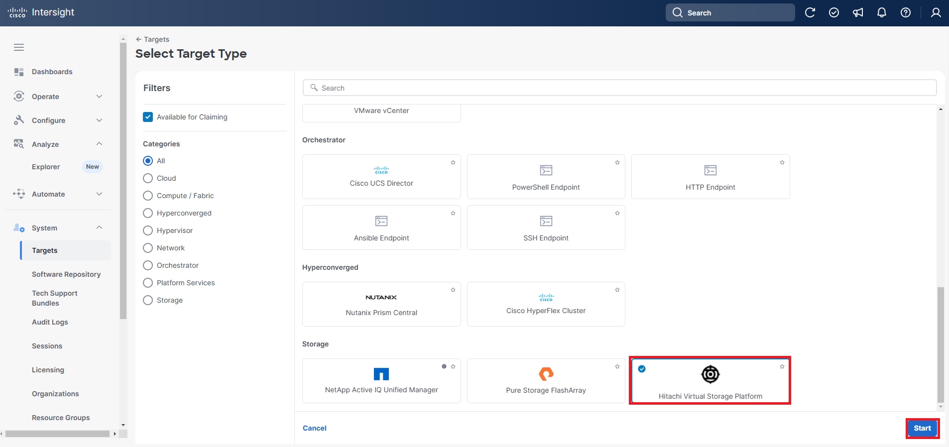
Step 5. Enter the following details to claim the Hitachi Virtual Storage Platform Target:
a. From the Intersight Assist list, select the deployed Intersight Assist Virtual Appliance Hostname/IP Address.
b. For VSP One Block Systems enter the Service IP.
c. Port: Enter 443.
d. Username: Enter the VSP storage system username.
e. Password: Enter the VSP storage system password.
f. Enable the Secure Connection option.
g. In the Hitachi Ops Center API Configuration Manager Address/Storage System Service IP Address field, enter the Storage System Service IP Address for the VSP One Block system.
Step 6. Click Claim.
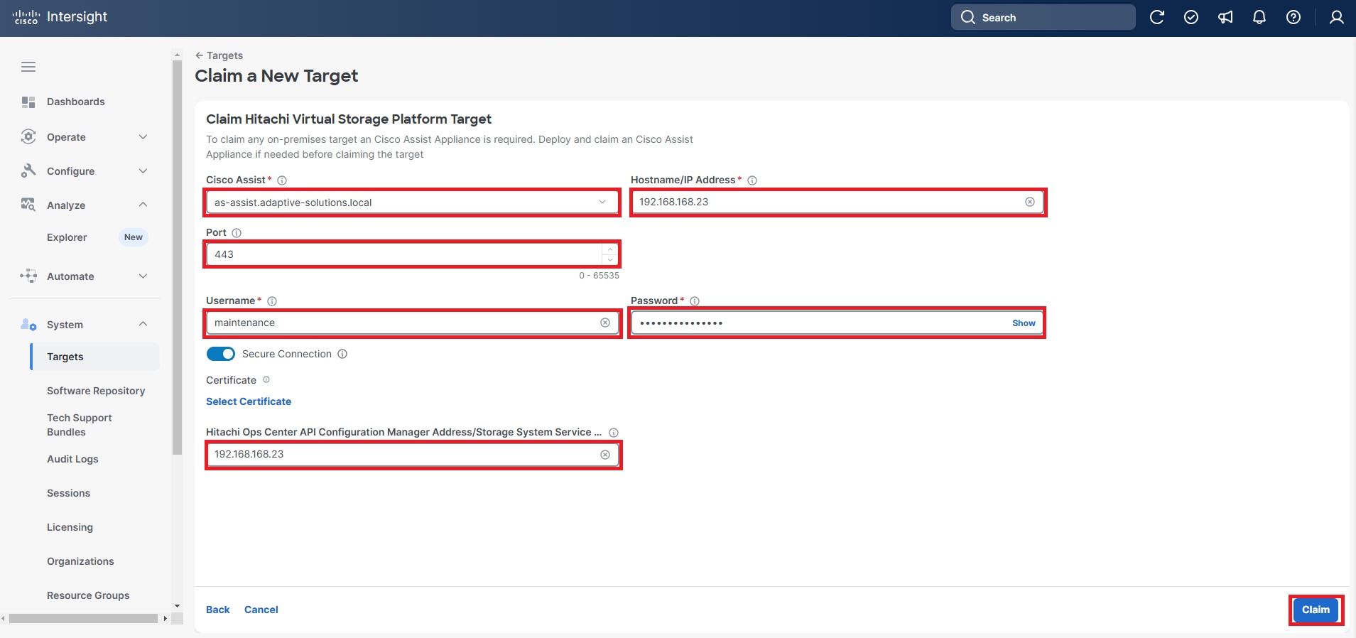
Step 7. Under System, click Targets and All Targets, verify that the newly connected Hitachi VSP storage appears with Device Type as Hitachi Virtual Storage Platform.
Step 8. View the properties of the added VSP storage systems under Operate > Storage.
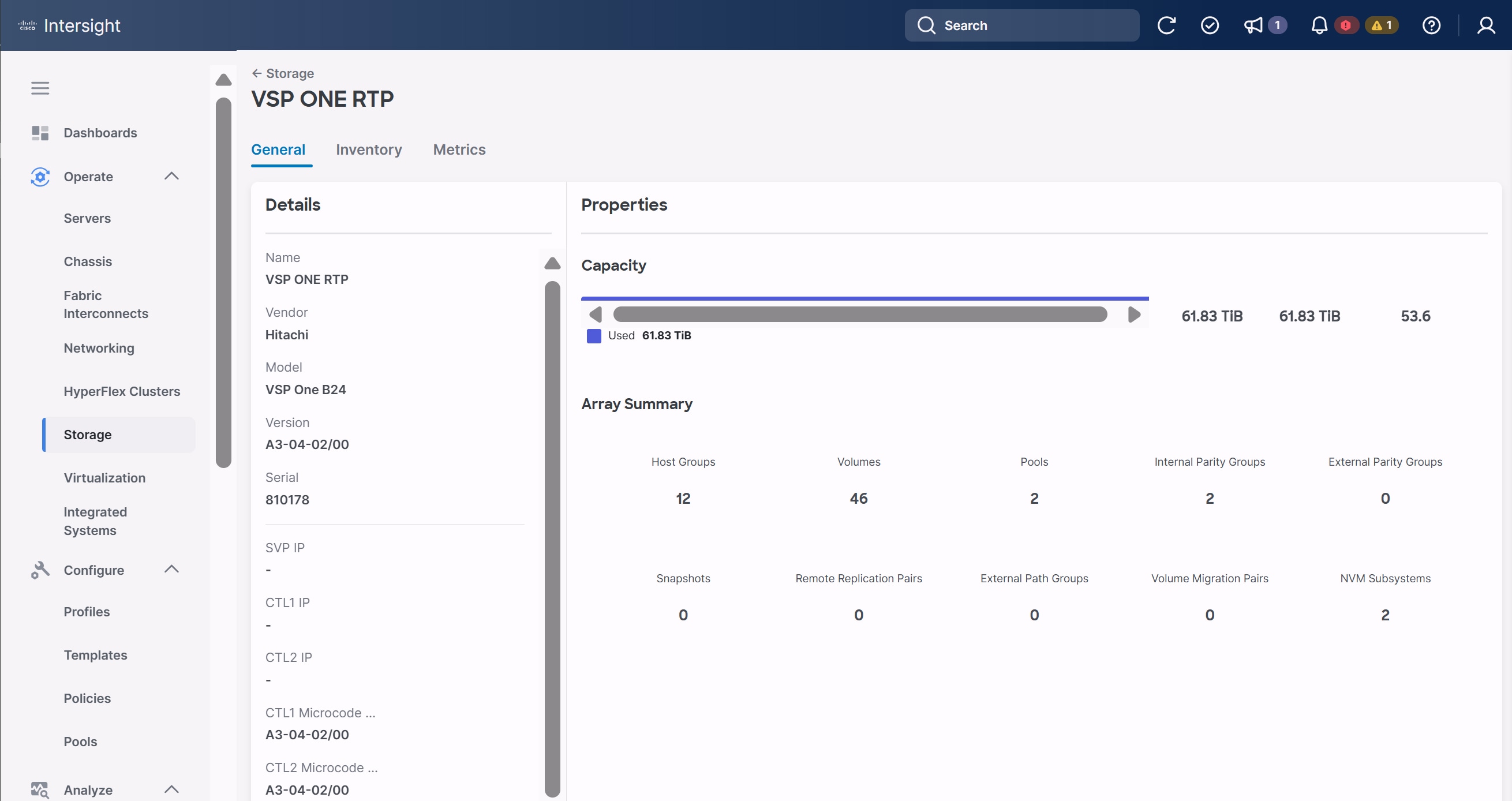
VMware vSphere 8.0 Update 3g Setup
This chapter contains the following:
● vSphere Cluster Image Update
● Add Remaining Hosts to vCenter
● Additional Settings on ESXi Hosts
This chapter provides detailed instructions for installing VMware ESXi 8.0U3 within Adaptive Solutions. On successful completion of these steps, multiple ESXi hosts will be provisioned and ready to be added to VMware vCenter.
Several methods exist for installing ESXi in a VMware environment. These procedures focus on how to use the built-in keyboard, video, mouse (KVM) console, and virtual media features in Cisco Intersight to map remote installation media to individual servers.
The VMware vSphere Hypervisor (ESXi) ISO can be downloaded from the Broadcom Support page, access to this will depend upon your contract and your access may vary.
Procedure 1. Log into Cisco Intersight and Access KVM
The Cisco Intersight KVM enables the administrators to begin the installation of the operating system (OS) through remote media. It is necessary to log into the Cisco Intersight to access the UCS Server KVM connections.
Step 1. Log into Cisco Intersight.
Step 2. From the main menu, go to Operate > Servers.
Step 3. Find the Server with the desired Server Profile assigned and click “…” to see more options.
Step 4. Click Launch vKVM.
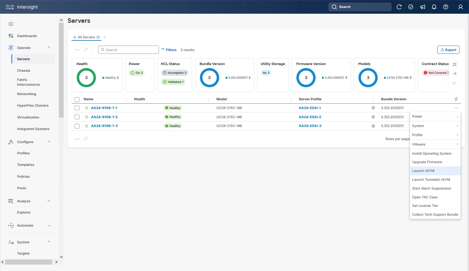
Step 5. Follow the prompts to ignore certificate workings (if any) and launch the HTML5 KVM console.
Step 6. Repeat steps 1 - 5 to launch the vKVM console for all the ESXi servers.
Procedure 2. Prepare the Server for the OS Installation
Note: Follow these steps on each ESXi host.
Step 1. In the KVM window, go to Virtual Media > vKVM-Mapped vDVD.
Step 2. Browse and select the ESXi installer ISO image file (VMware-VMvisor-Installer-8.0U3g-24859861.x86_64.iso).
Step 3. Click Map Drive.
Step 4. Go to Power > Reset System and Confirm to reboot the server if the server is showing a shell prompt. If the server is shut down, click Power > Power On System.
Step 5. Monitor the server boot process in the KVM. The server should find the boot LUNs and begin to load the ESXi installer.
Note: If the ESXi installer fails to load because the software certificates cannot be validated, reset the server, and when prompted, press F2 to go into BIOS and set the system time and date to current. The ESXi installer should load properly.
Procedure 3. Install VMware ESXi onto the M.2 Virtual Disk of the UCS Servers
Note: Follow these steps on each host.
Step 1. After the ESXi installer is finished loading (from the last step), press Enter to continue with the installation.
Step 2. Read and accept the end-user license agreement (EULA). Press F11 to accept and continue.
Note: It may be necessary to map function keys as User Defined Macros under the Macros menu in the KVM console.
Step 3. Select the appropriate disk for the RAID 1 configured M.2 drives. Press Enter to continue with the installation.
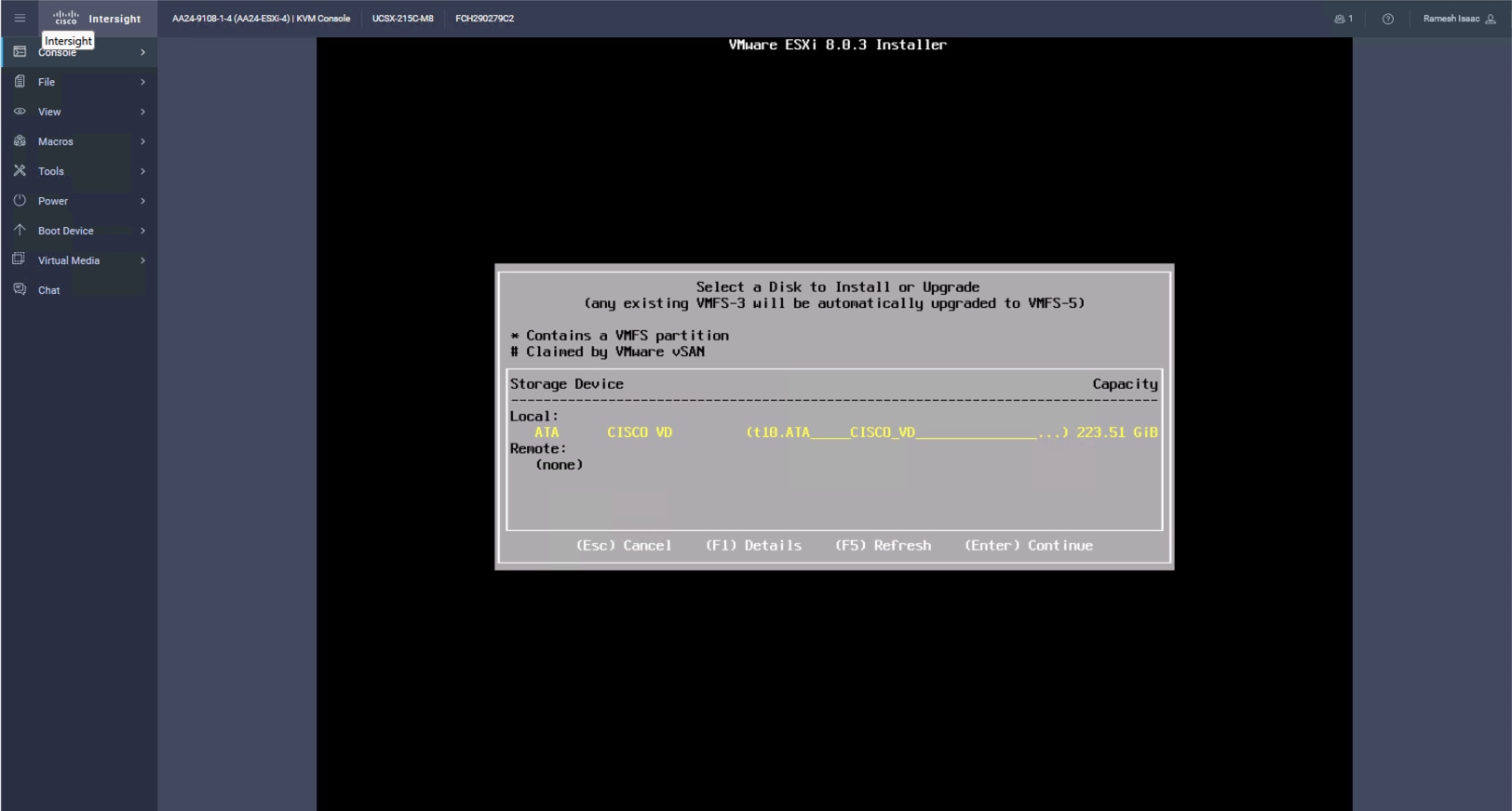
Step 4. Select the appropriate keyboard layout and press Enter.
Step 5. Enter and confirm the root password and press Enter.
Step 6. The installer issues a warning that the selected disk will be repartitioned. Press F11 to continue with the installation.
Step 7. After the installation is complete, press Enter to reboot the server. The ISO will be unmapped automatically.
Procedure 4. Add the Management Network for each VMware Host
Note: This procedure is required for managing the host. To configure the ESXi host with access to the management network, follow these steps on each ESXi host.
Step 1. After the server has finished rebooting, in the UCS KVM console, press F2 to customize VMware ESXi.
Step 2. Log in as root, enter the password set during installation, and press Enter to log in.
Step 3. Use the down arrow key to choose Troubleshooting Options and press Enter.
Step 4. Select Enable ESXi Shell and press Enter.
Step 5. Select Enable SSH and press Enter.
Step 6. Press Esc to exit the Troubleshooting Options menu.
Step 7. Select the Configure Management Network option and press Enter.
Step 8. Select Network Adapters and press Enter. Ensure the vmnic numbers align with the numbers under the Hardware Label (for example, vmnic0 and 00-vSwitch0-A). If these numbers do not align, note which vmnics are assigned to which vNICs (indicated under Hardware Label).
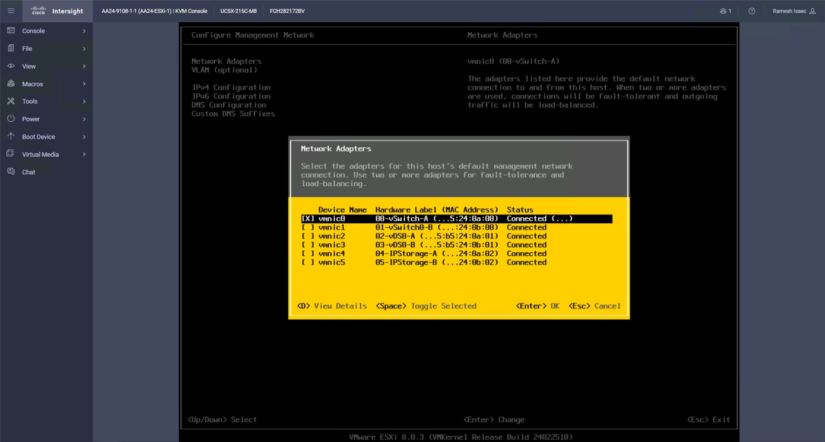
Step 9. Arrow down to select vmnic1 and press the spacebar to select it.
Step 10. Press Enter.
Note: In the UCS Configuration portion of this document, the IB-MGMT VLAN was set as the native VLAN on the 00-vSwitch0-A and 01-vSwitch0-B vNICs. Because of this, the IB-MGMT VLAN should not be set here and should remain Not set.
Step 11. Select IPv4 Configuration and press Enter.
Note: When using DHCP to set the ESXi host networking configuration, setting up a manual IP address is not required.
Step 12. Select the Set static IPv4 address and network configuration option by using the arrow keys and space bar.
Step 13. Under IPv4 Address, enter the IP address for managing the ESXi host.
Step 14. Under Subnet Mask, enter the subnet mask.
Step 15. Under Default Gateway, enter the default gateway.
Step 16. Press Enter to accept the changes to the IP configuration.
Step 17. Select the IPv6 Configuration option and press Enter.
Step 18. Using the spacebar, choose Disable IPv6 (restart required) and press Enter.
Step 19. Select the DNS Configuration option and press Enter.
Step 20. If the IP address is configured manually, the DNS information must be provided.
Step 21. Using the spacebar, select the following DNS server addresses and hostname:
● Under Primary DNS Server, enter the IP address of the primary DNS server.
● Optional: Under Alternate DNS Server, enter the IP address of the secondary DNS server.
● Under Hostname, enter the fully qualified domain name (FQDN) for the ESXi host.
● Press Enter to accept the changes to the DNS configuration.
● Press Esc to exit the Configure Management Network submenu.
● Press Y to confirm the changes and reboot the ESXi host.
Procedure 5. (Optional) Reset VMware ESXi Host VMkernel Port MAC Address
Note: By default, the MAC address of the management VMkernel port vmk0 is the same as the MAC address of the Ethernet port it is placed on. If the ESXi host’s boot LUN is remapped to a different server with different MAC addresses, a MAC address conflict will exist because vmk0 will retain the assigned MAC address unless the ESXi System Configuration is reset.
Step 1. From the ESXi console menu main screen, select Macros > Static Macros > Ctrl + Alt + F’s > Ctrl + Alt + F1 to access the VMware console command line interface.
Step 2. Log in as root.
Step 3. Type “esxcfg-vmknic –l” to get a detailed listing of interface vmk0. vmk0 should be a part of the “Management Network” port group. Note the IP address and netmask of vmk0.
Step 4. To remove vmk0, type esxcfg-vmknic –d “Management Network”.
Step 5. To add vmk0 with a random MAC address, type esxcfg-vmknic –a –i <vmk0-ip> -n <vmk0-netmask> “Management Network”.
Step 6. Verify vmk0 has been added with a random MAC address by typing esxcfg-vmknic –l.
Step 7. Tag vmk0 as the management interface by typing esxcli network ip interface tag add -i vmk0 -t Management.
Step 8. When vmk0 was added, if a message displays stating vmk1 was marked as the management interface, type esxcli network ip interface tag remove -i vmk1 -t Management.
Step 9. Press Ctrl-D to log out of the ESXi console.
Step 10. Select Macros > Static Macros > Ctrl + Alt + F’s > Ctrl + Alt + F2 to return to the VMware ESXi menu.
With the UCS servers finished with their ESXi installation and basic configuration, they can now be added to the vCenter.
Note: In the validated environment, the vCenter is deployed within an existing management cluster independent of the Adaptive Solutions VSI environment. The vCenter Appliance could be deployed within the VSI itself with a first host that is configured through the vSphere web client and had the VSP VMFS datastores associated to it, but that is not covered in our deployment example.
Procedure 1. Add deployed ESXi instances to the vCenter
Step 1. Open a web browser and navigate to the vCenter server.
Step 2. Select the main menu icon to open the menu options and select the Inventory option.
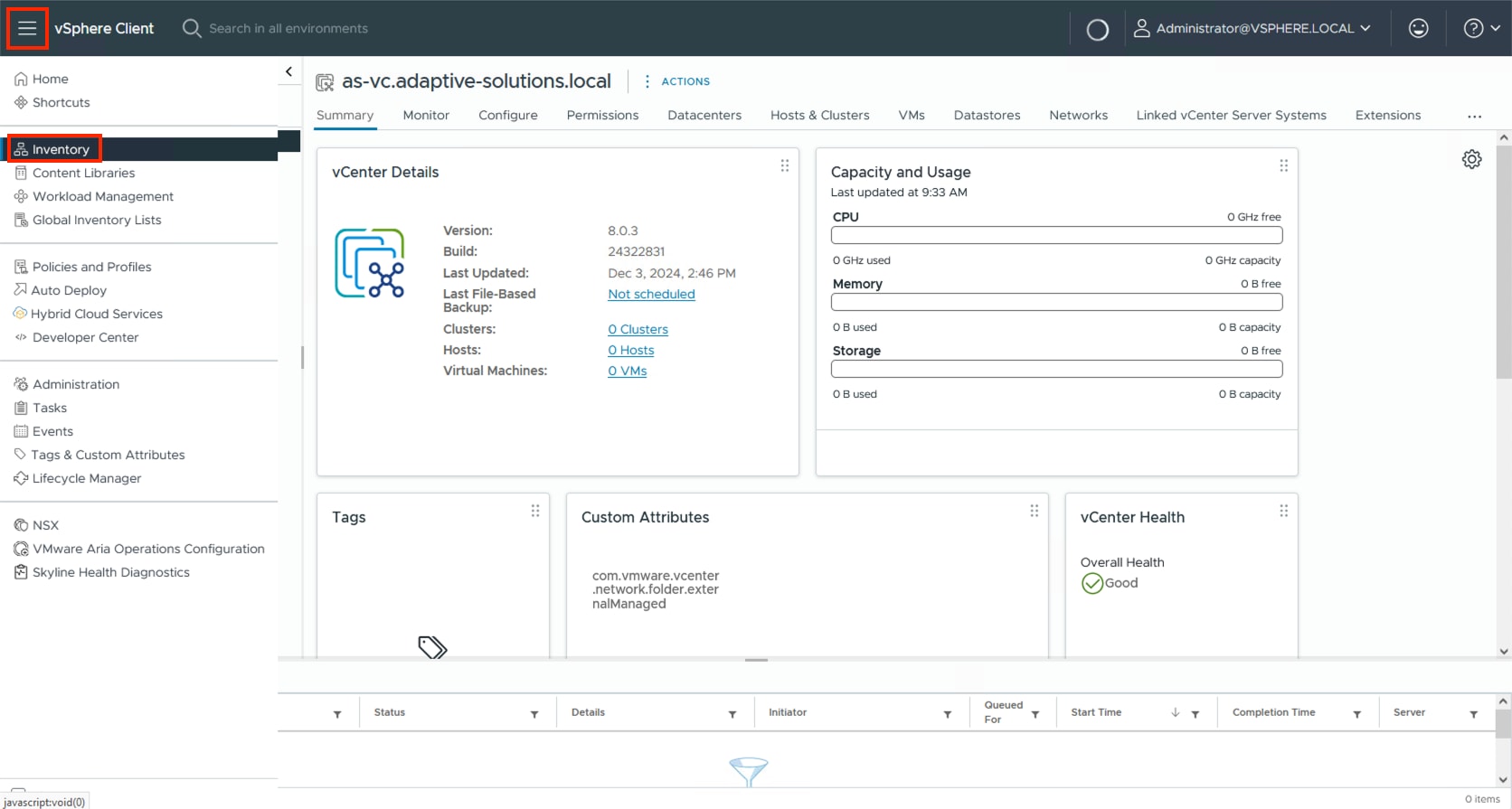
Step 3. If there is not an established Datacenter object within the vCenter, right-click the vCenter on the left and select New Datacenter… and provide the Datacenter with an appropriate name.
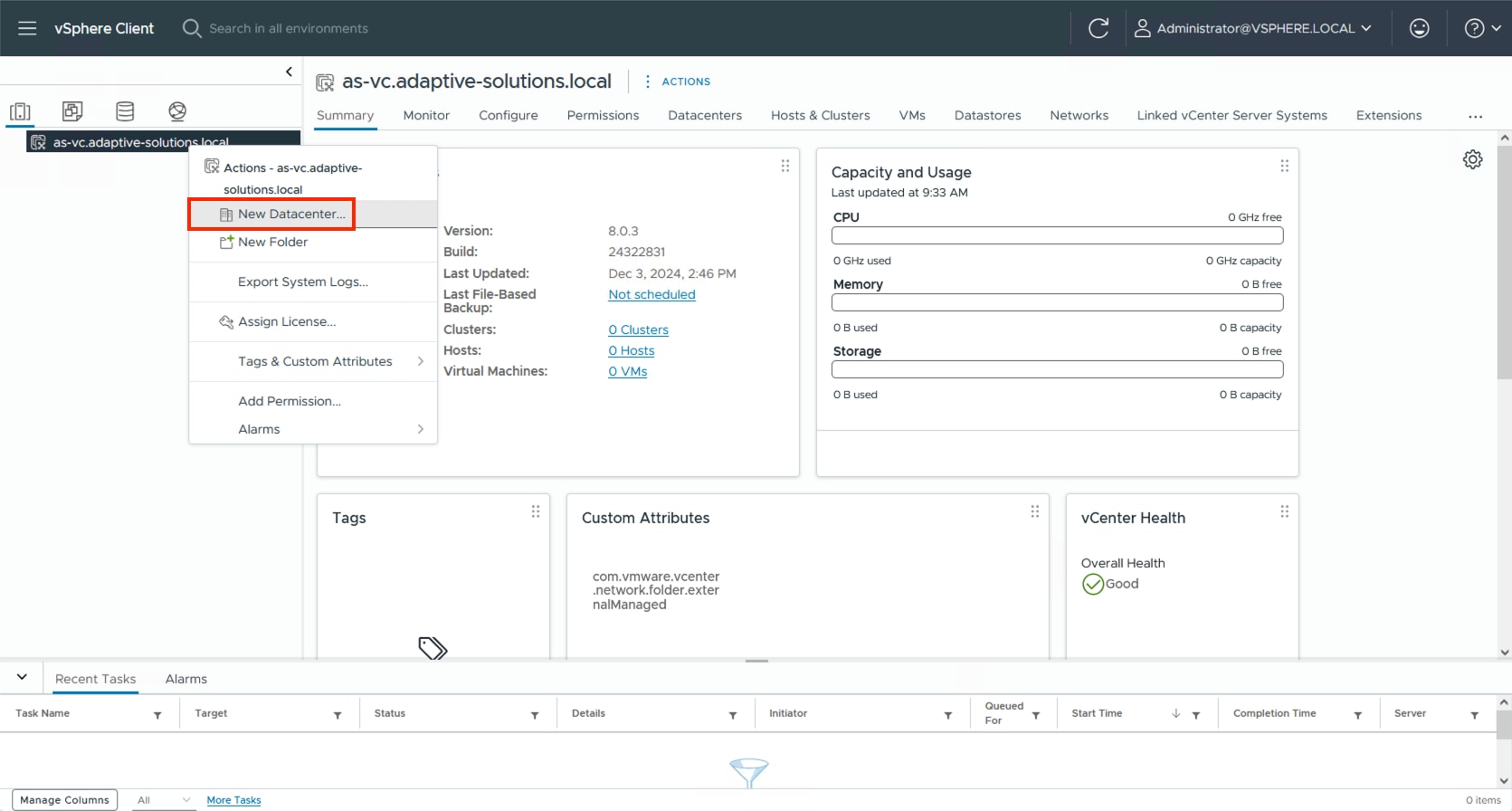
Step 4. Right-click the Datacenter object and select the New Cluster… option.
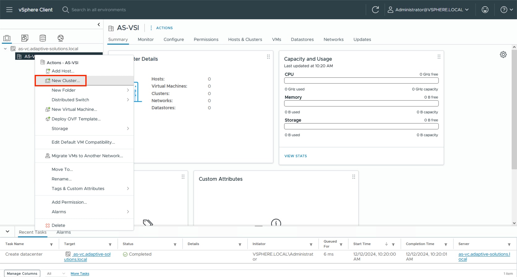
Step 5. Provide a name for the Cluster, enable vSphere DRS and vSphere HA, select Import image from a new host, check the box for Manage configuration at a cluster level, and click NEXT.
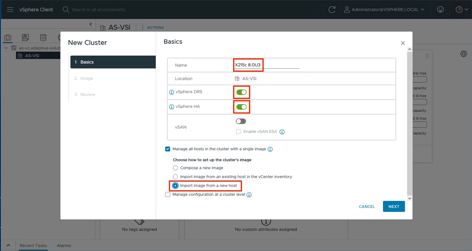
Step 6. Enter the IP or FQDN of the first host, enter root for the username, and provide the password specified during initial setup. Click FIND HOST.
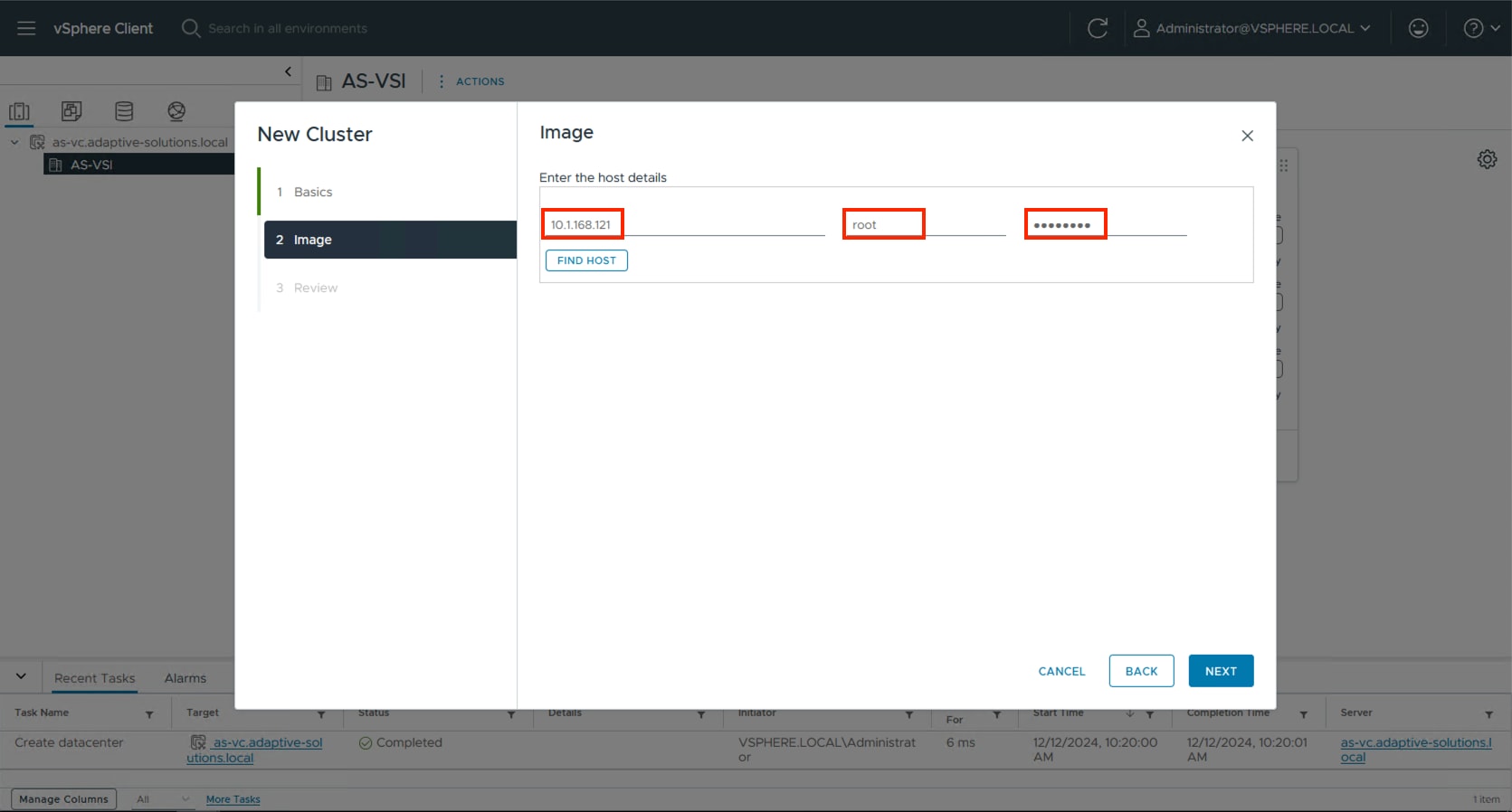
Step 7. Click Yes past the Security Alert if prompted.
Step 8. Confirm the host is found correctly. Leave Also move select host to cluster selected and click Next.
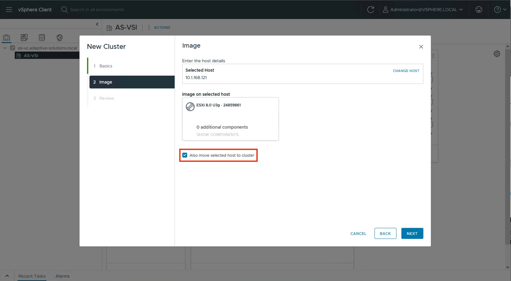
Step 9. Click NEXT past the Configuration screen dialogue summary. Confirm the cluster options and image setup within Review and click FINISH.
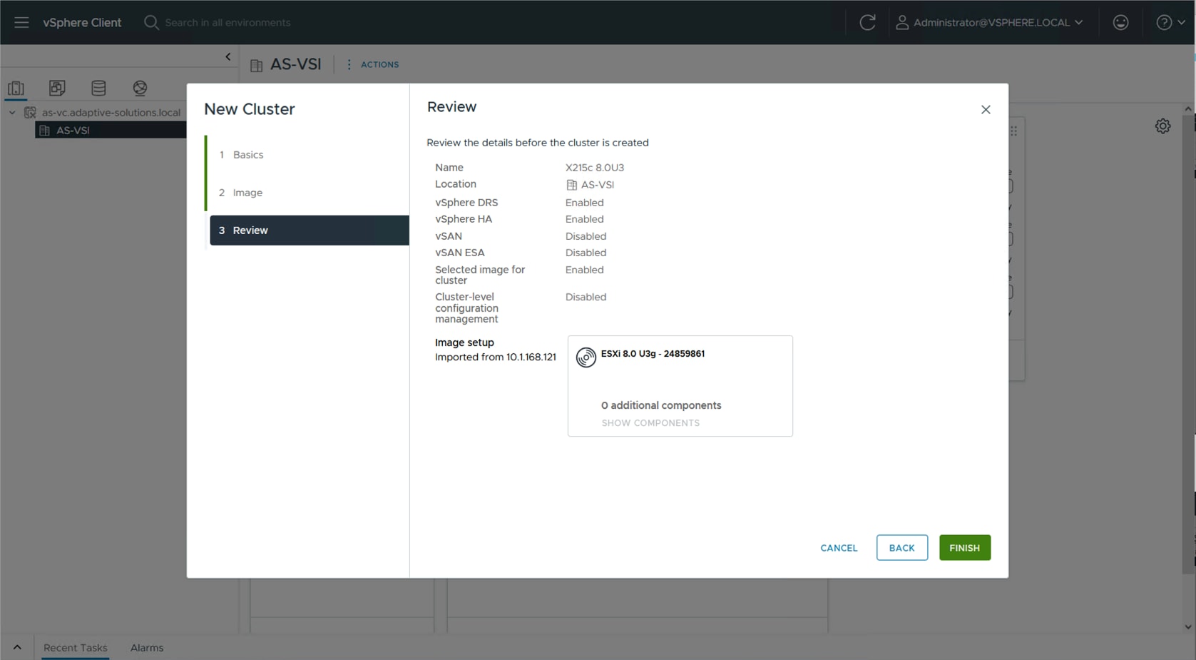
Note: The added ESXi host will have Warnings that the ESXi Shell and SSH have been enabled. These warnings can be suppressed. The host will also have a TPM Encryption Key Recovery alert that can be acknowledged and reset to green.
The vSphere Cluster Image for ESXi 8.0U3 will be adjusted to associate with the Cisco UCS Addon for ESXi to align with the appropriate nenic, UCS Tool, and so on, as component VIBs (vSphere Installation Bundle). Additionally, for continued compliance, the Hardware Support Manager will be associated to the Intersight Assist that was previously created to update the host firmware as needed.
Procedure 1. Download the required drivers and addons
The required drivers and addons will need to be download to a system that will later be able to upload them to the vCenter.
Step 1. To determine the required components go to the UCS Hardware and Software Compatibility page.
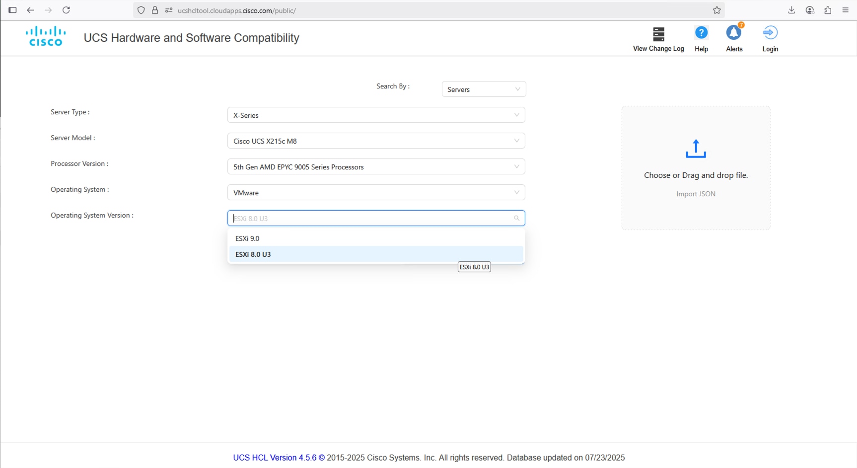
Step 2. Find the appropriate Firmware and select the CNA option.
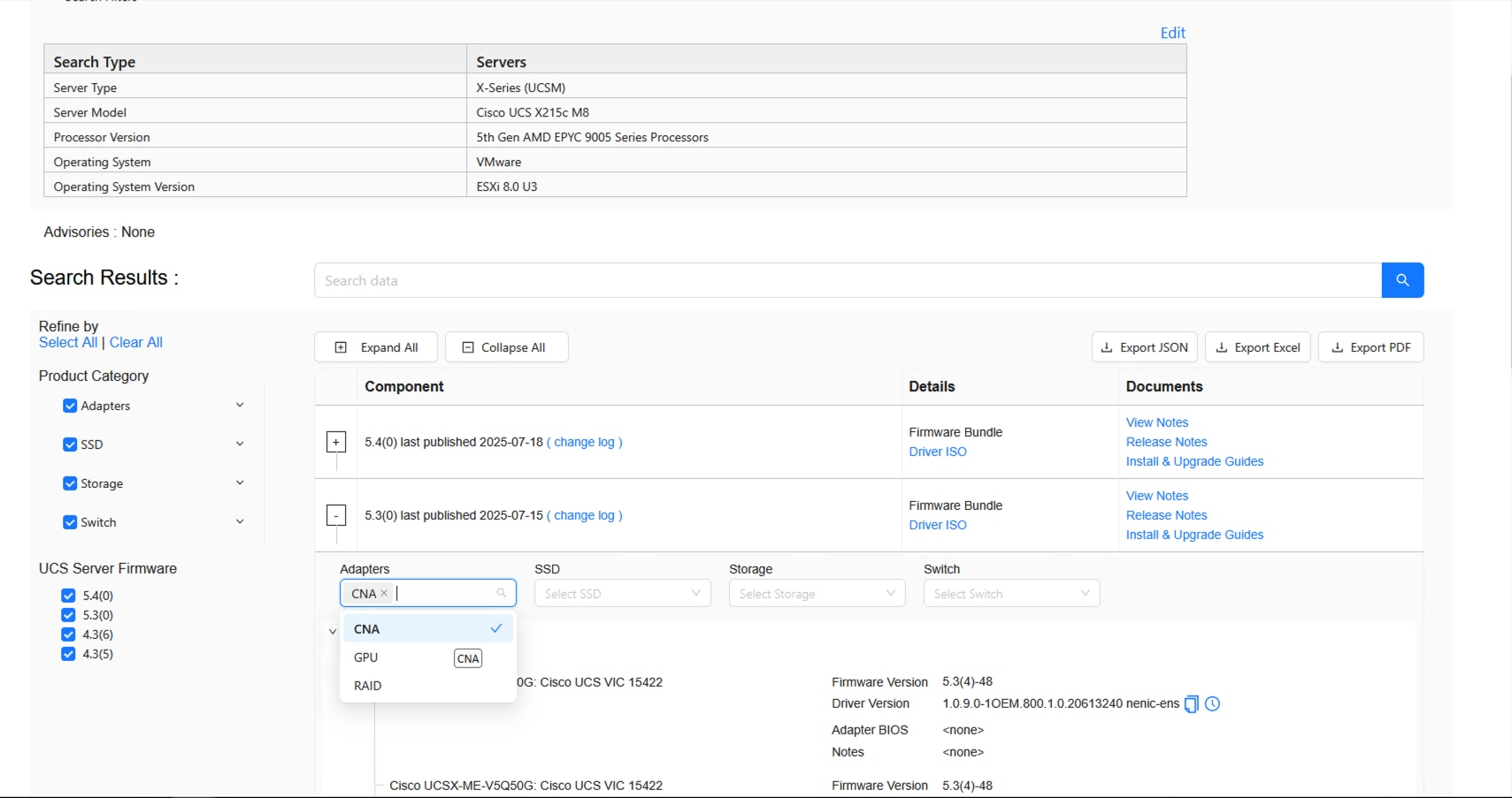
Step 3. Find the adapter and identify the required nenic.
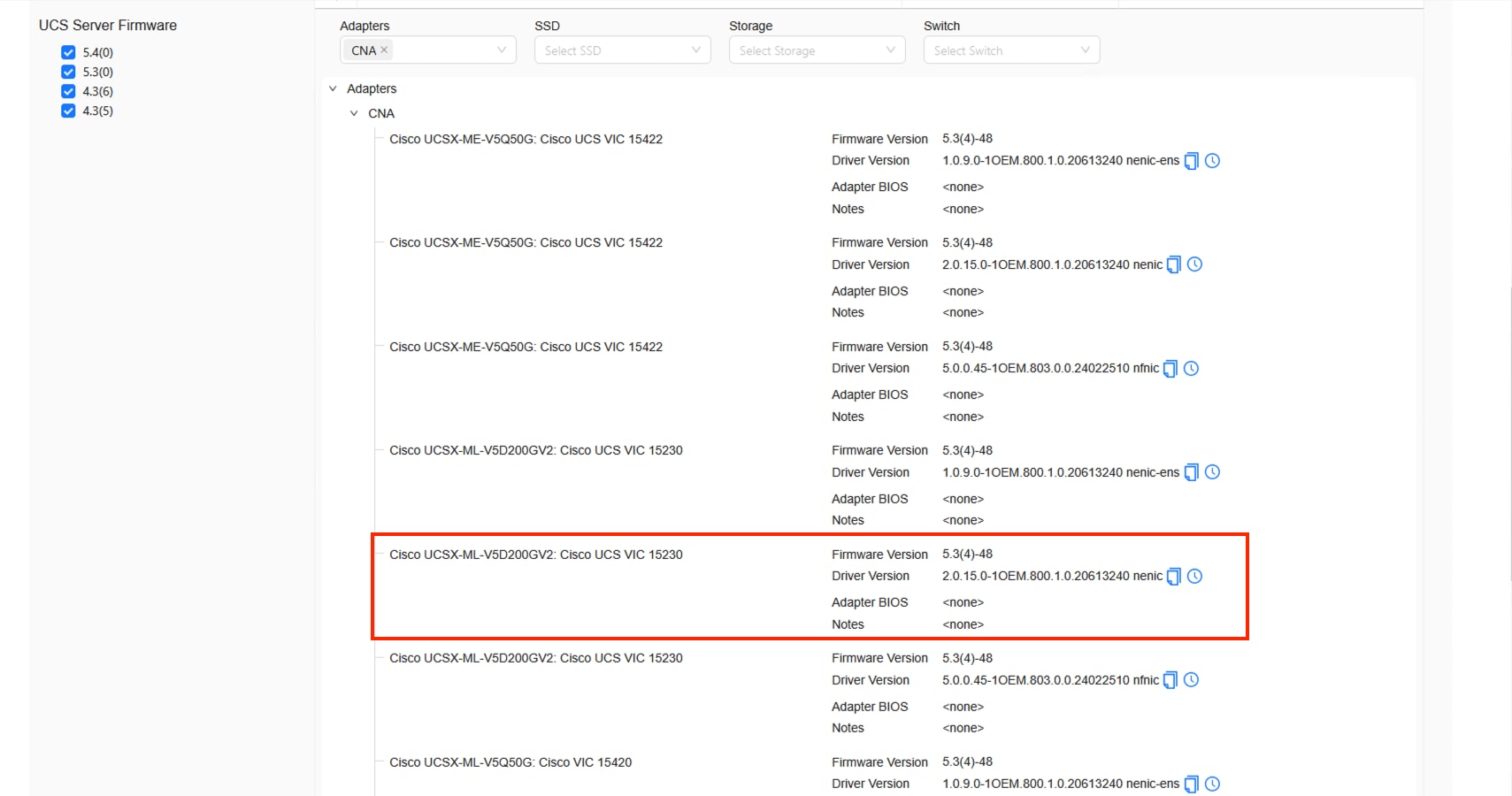
Step 4. Open the Cisco Software Download page and select the appropriate ISO.
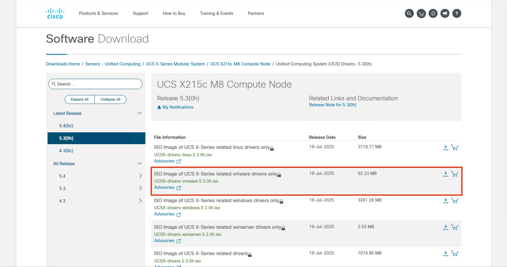
Step 5. Find the zip file for this driver after mounting the ISO and go to Network > Cisco > VIC > ESXi8.0U3 > nenic.
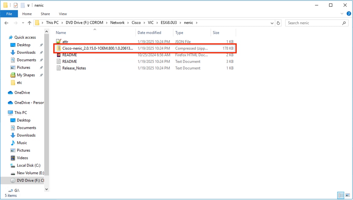
Step 6. The zip file within this folder is a package file that will need to be copied elsewhere to find the contained driver zip that will be used.
Step 7. Download the Cisco UCS Tools from the Software Download page.
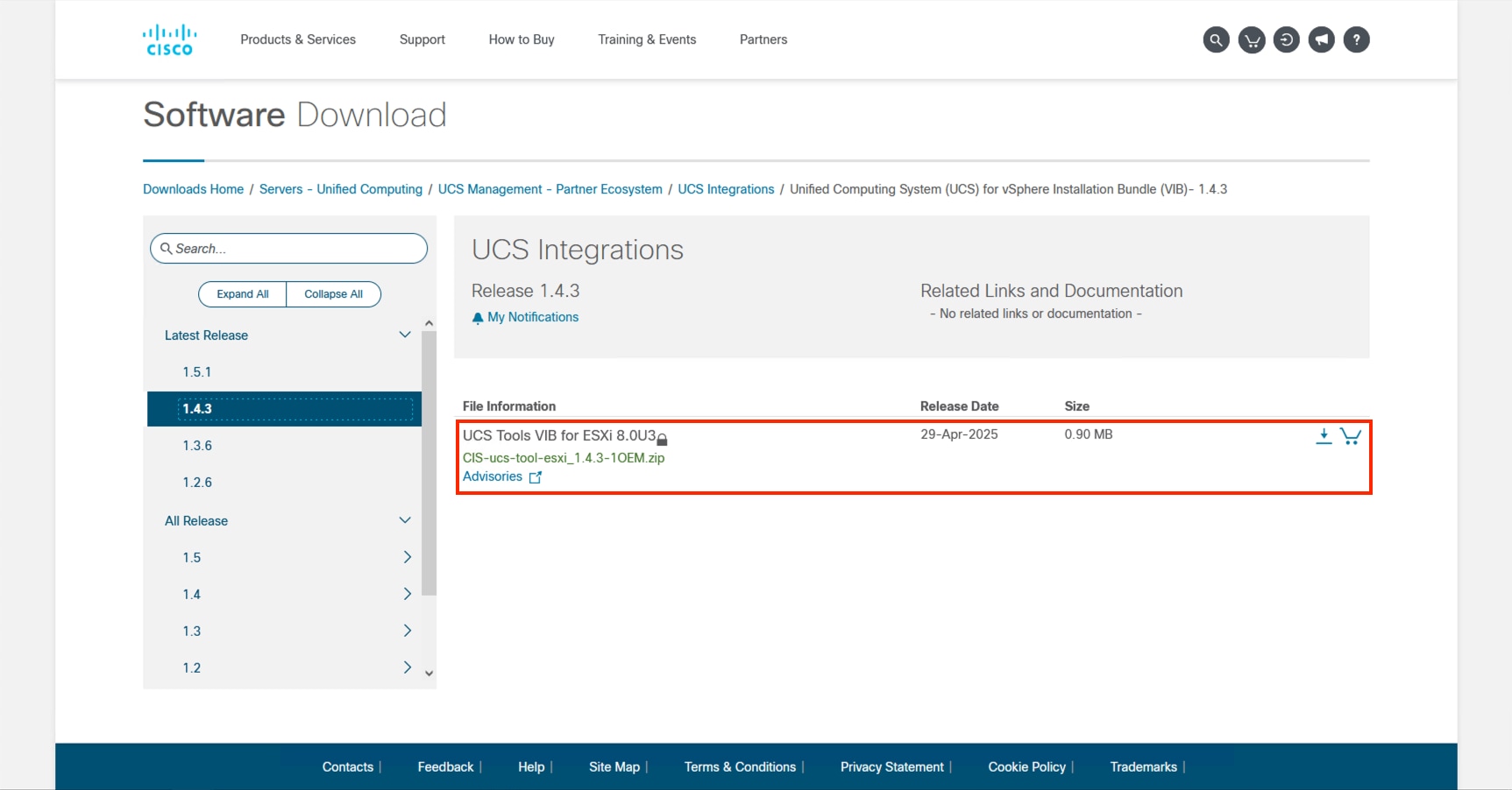
Procedure 2. Import zip files into Lifecycle Manager
Return to vCenter and perform the following steps:
Step 1. Click the main menu icon to open the left side menu and select the Lifecycle Manager option.
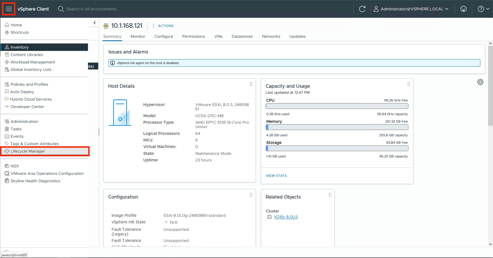
Step 2. Click ACTIONS and select the Import Updates option.
Step 3. Click BROWSE and find the driver zip (Cisco-nenic_2.0.15.0-1OEM.800.1.0.20613240_24387781.zip) that was extracted from the package zip within the ISO and click Open.
The driver should now appear within the Components section at the bottom of the page:
Step 4. Click ACTIONS and select the Import Updates option.
Step 5. BROWSE and navigate to the location of the downloaded UCS Tools VIB and click Open.
The UCS Tools will display within the Components.
Procedure 3. Update Cluster Image
Return to the cluster and perform the following steps to the cluster image.
Step 1. Select the cluster, click the Updates tab, and then click EDIT within the Image section.
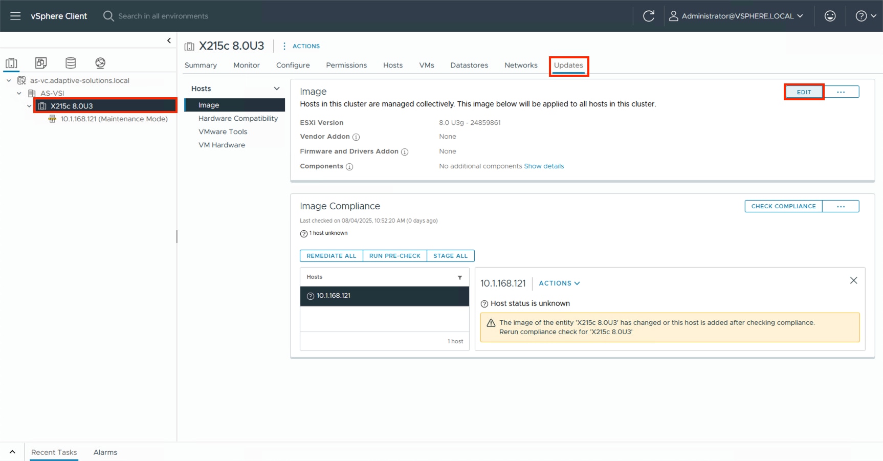
Step 2. Click the Show details option for the Components.
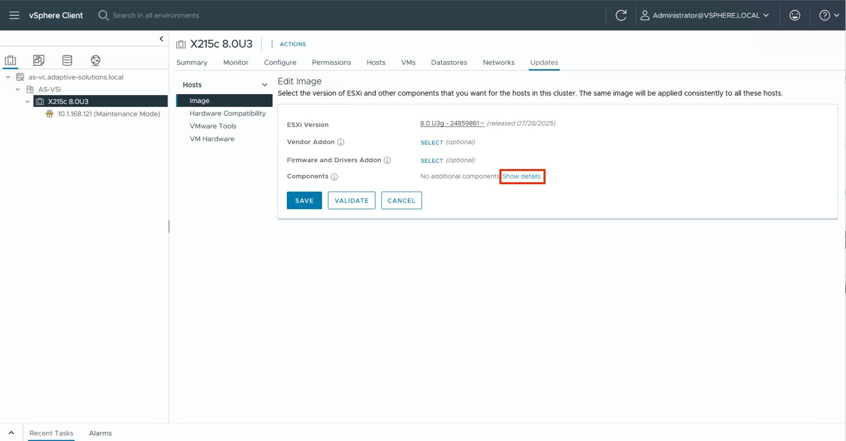
Step 3. Click ADD COMPONENTS.
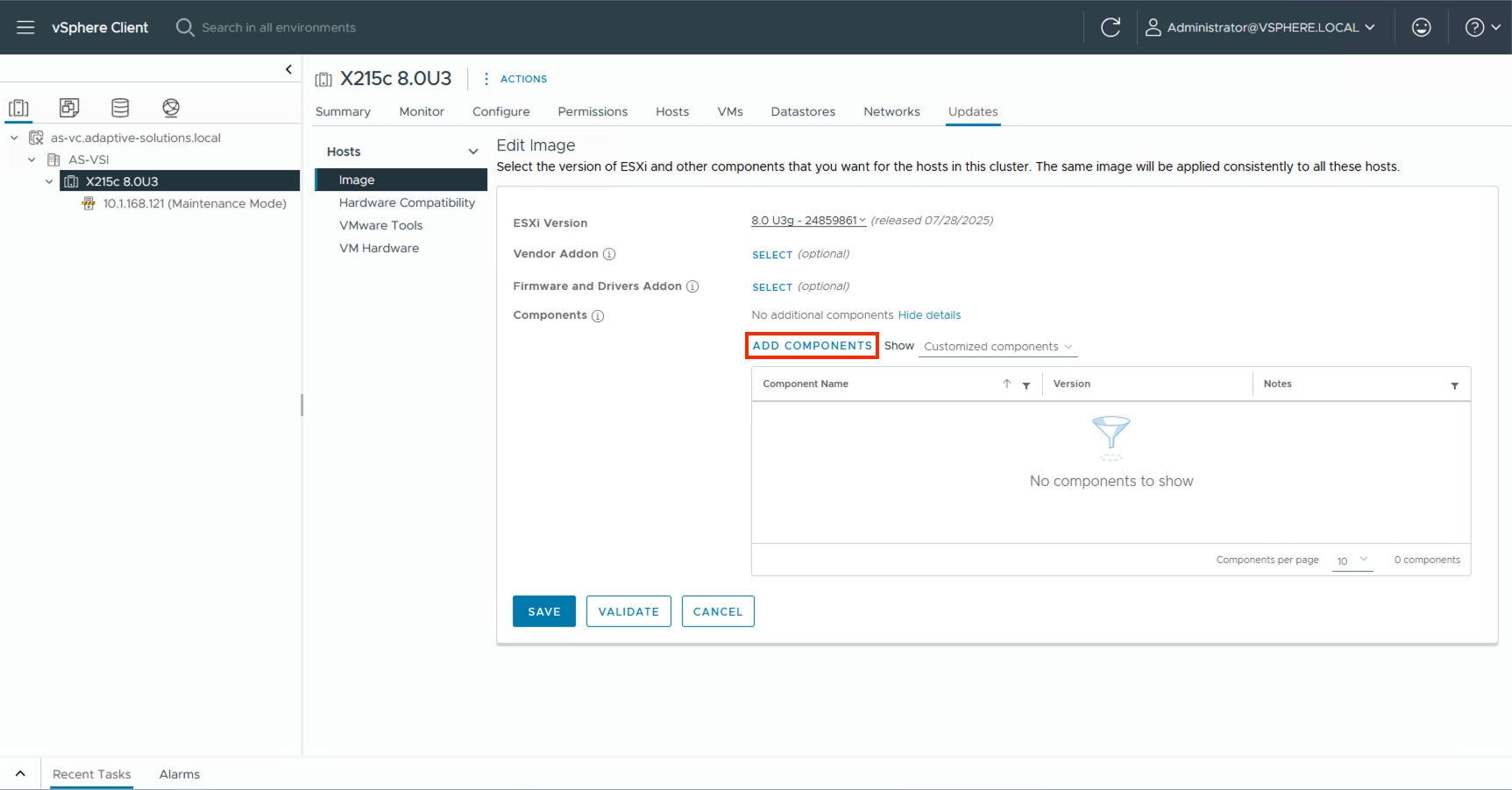
Step 4. Click the imported components and click SELECT.
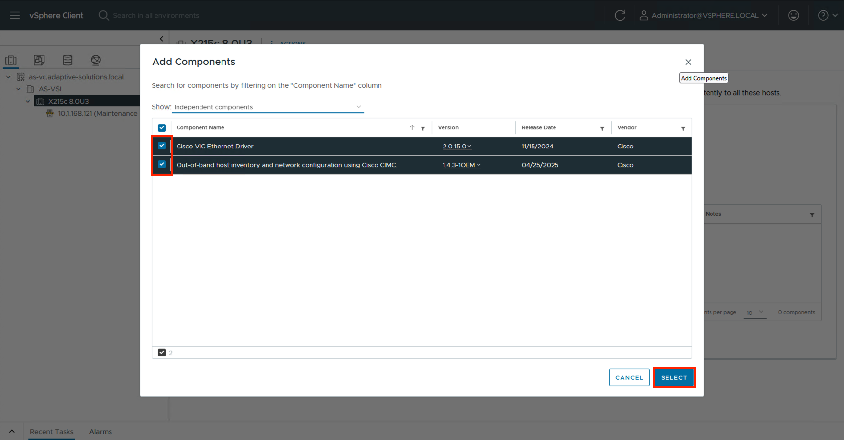
Step 5. Click SELECT for the Firmware and Drivers Addon.
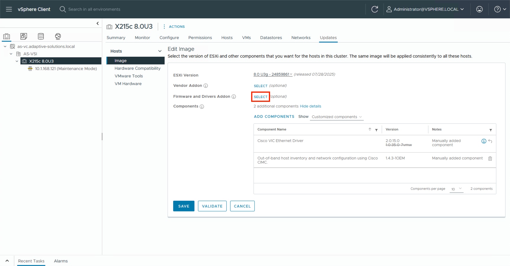
Step 6. From the drop-down list under Select the hardware support manager, select the previously installed Intersight Assist.
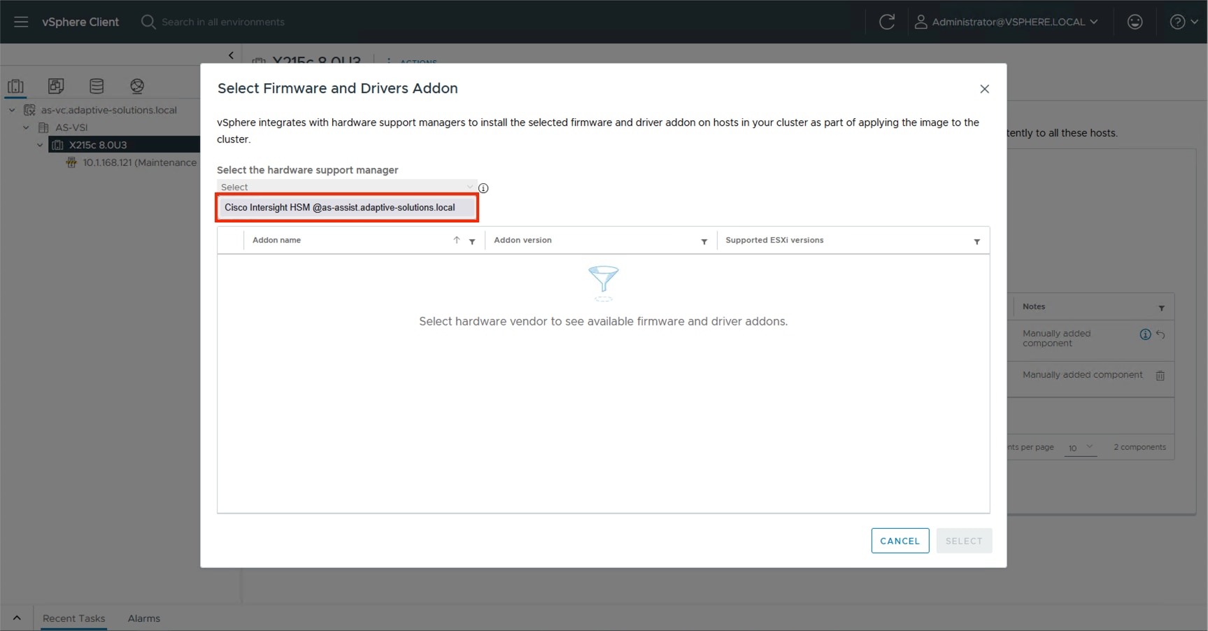
Step 7. Find the recommended firmware and driver addon that corresponds with the currently identified firmware for the X215c servers.
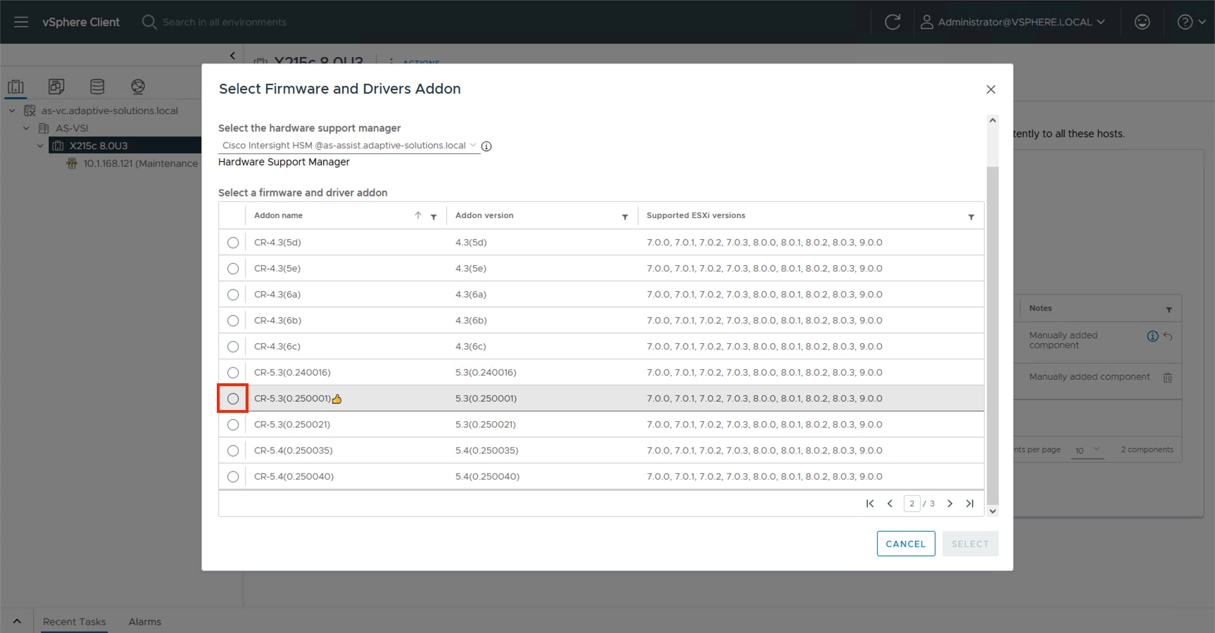
Step 8. Click Select.
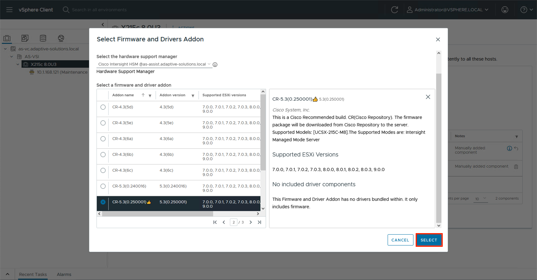
Step 9. Click Validate.
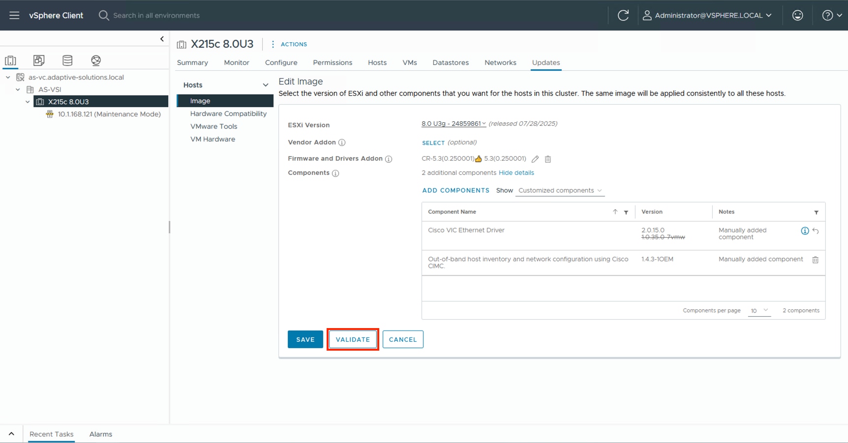
Step 10. Confirm the image is valid and click SAVE.
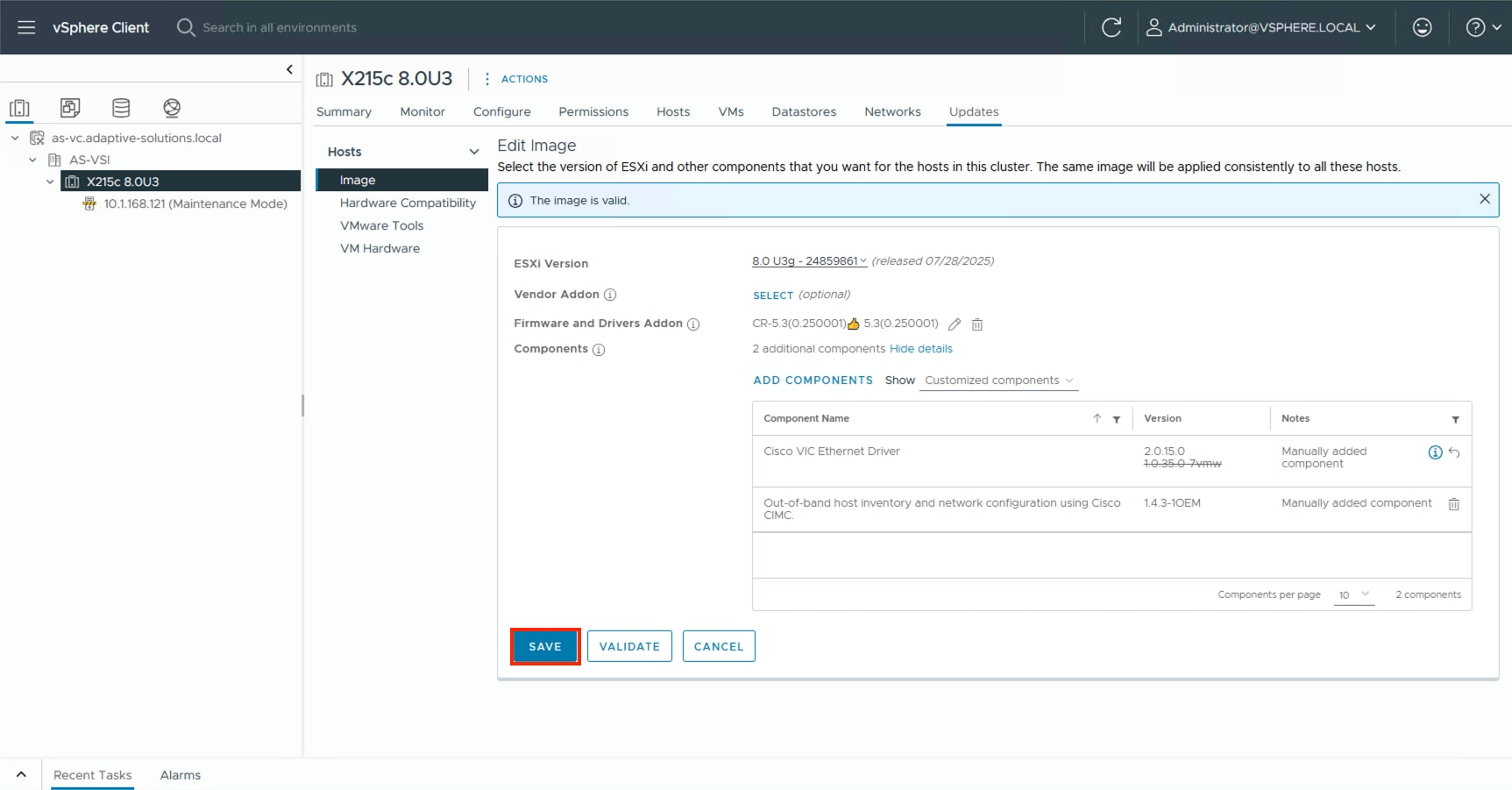
Add Remaining Hosts to vCenter
This procedure details the steps to add and configure an ESXi host in vCenter.
Procedure 1. Add the ESXi Hosts to vCenter
Step 1. From the Home screen in the VMware vCenter HTML5 Interface, select Hosts and Clusters.
Step 2. Right-click the cluster and click Add Hosts.
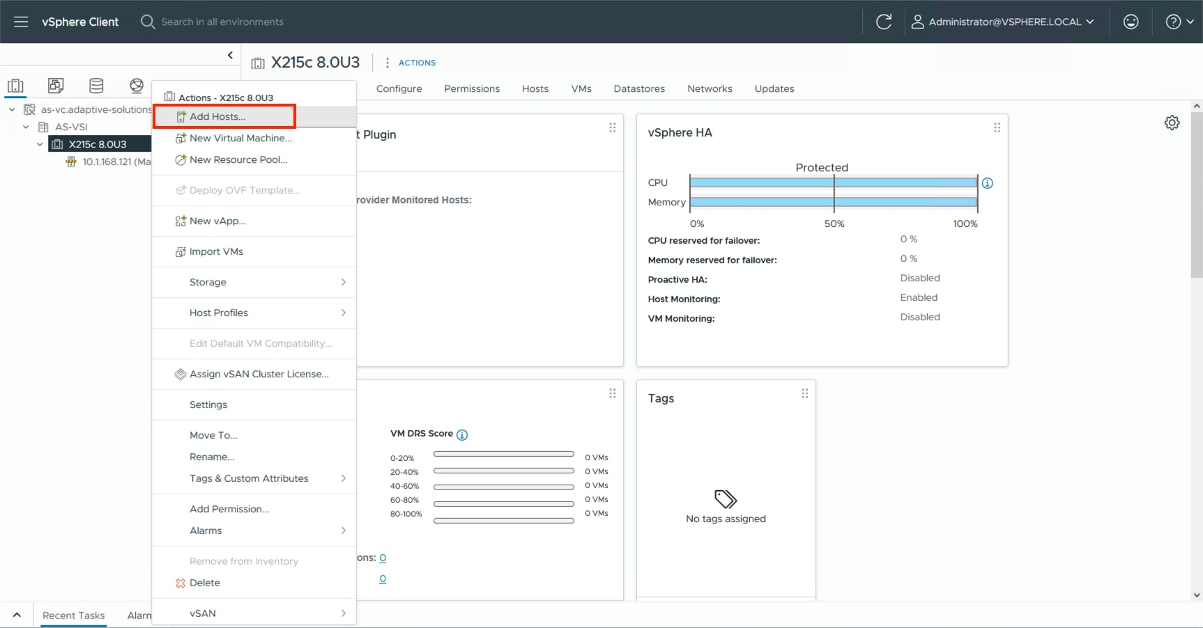
Step 3. In the IP address or FQDN field, enter either the IP address or the FQDN name of the configured VMware ESXi host. Enter the user id (root) and associated password. If more than one host is being added, add the corresponding host information, optionally selecting “Use the same credentials for all hosts.” Click NEXT.
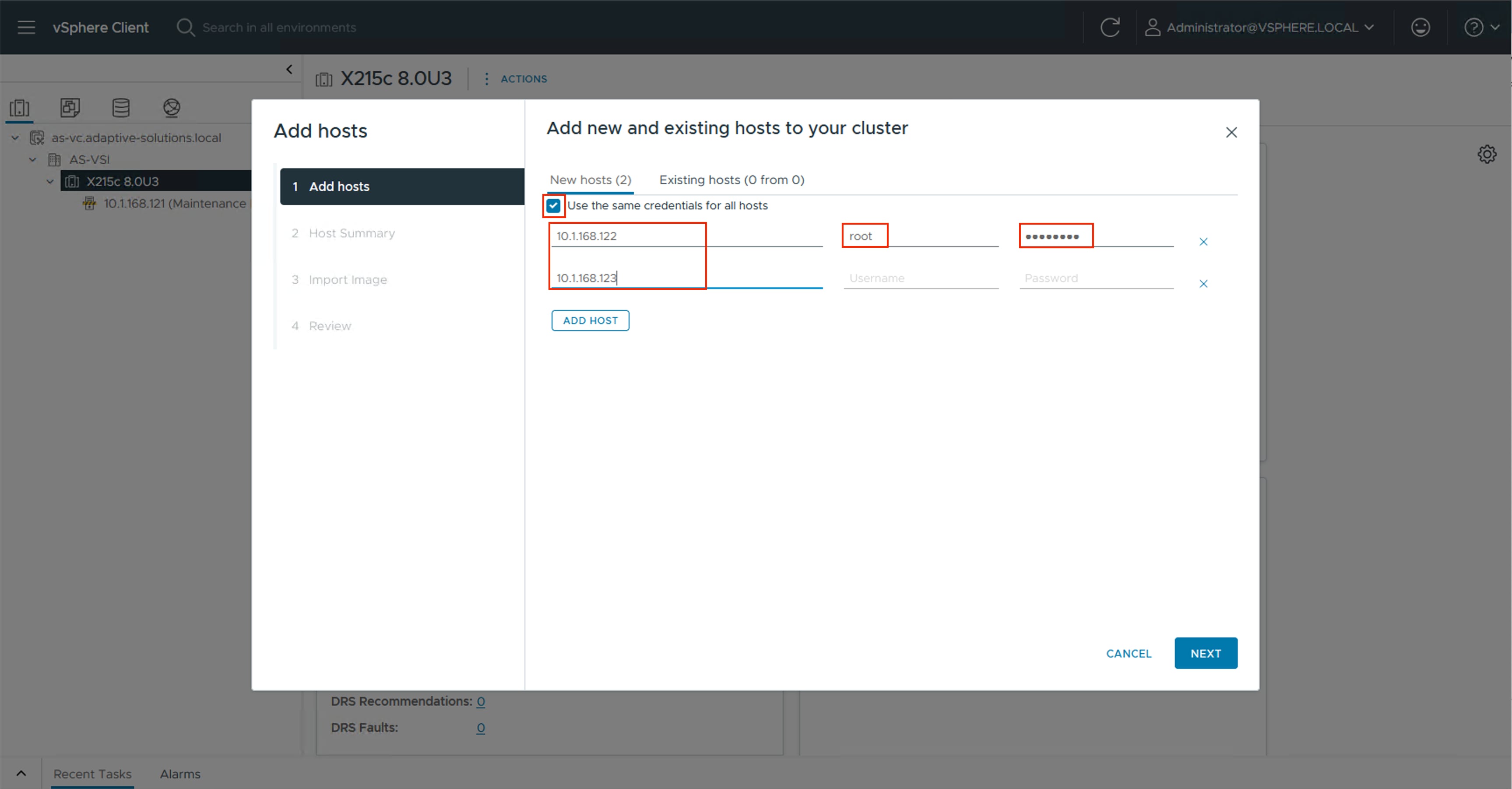
Step 4. Select all hosts to add and click OK to accept the thumbprint(s) when prompted with the Security Alert pop-up.
Step 5. Review the host details and click NEXT to continue.
Step 6. Leave Don’t import an image selected and then click NEXT.
Step 7. Review the configuration parameters and click FINISH to add the host(s).
Note: The added ESXi host(s) will be placed in Maintenance Mode and will have Warnings that the ESXi Shell and SSH have been enabled. These warnings can be suppressed. The TPM Encryption Recovery Key Backup Alarm can also be Reset to Green.
Procedure 2. Image Reconciliation on Added Hosts
Step 1. Go to Updates > Hosts > Image for the VSI cluster and select RUN PRE-CHECK.
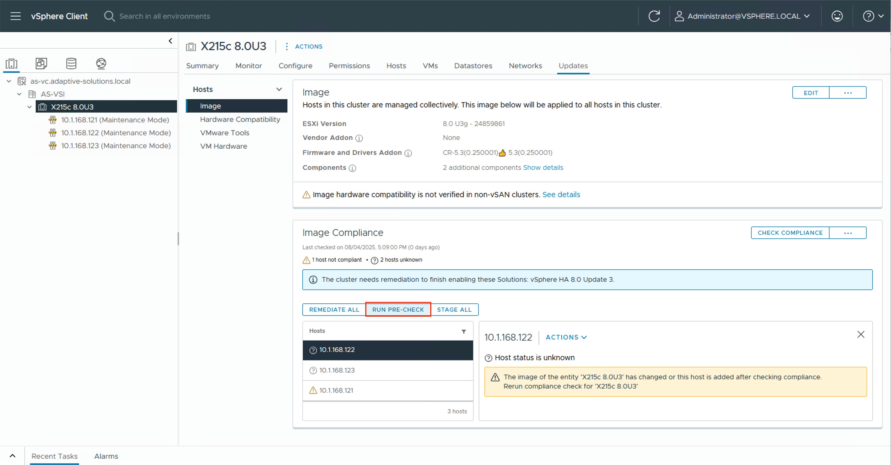
Step 2. After the pre-check resolves, click REMEDIATE ALL.
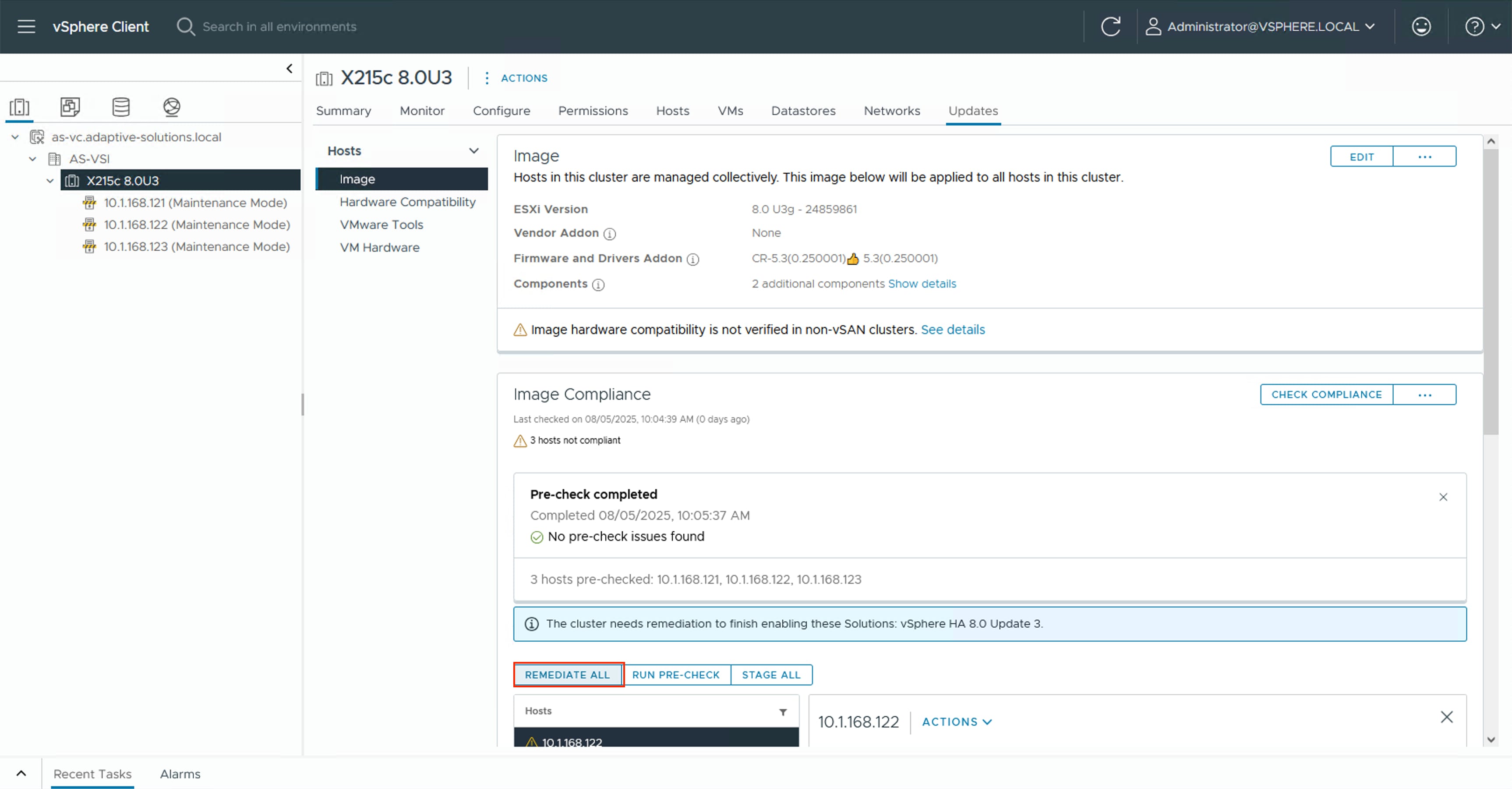
Step 3. Click START REMEDIATION.
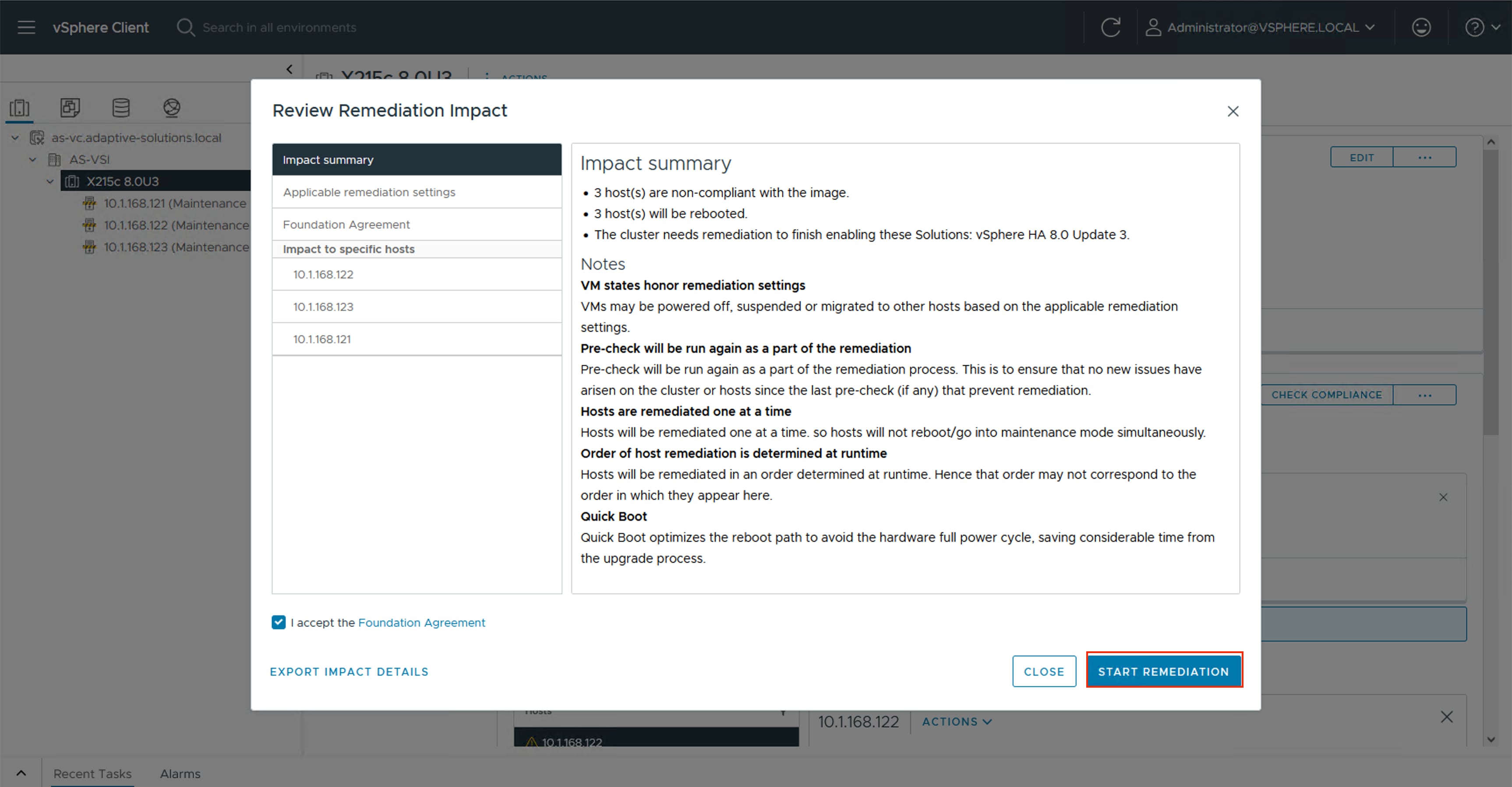
Step 4. Confirm the remediation has completed successfully.
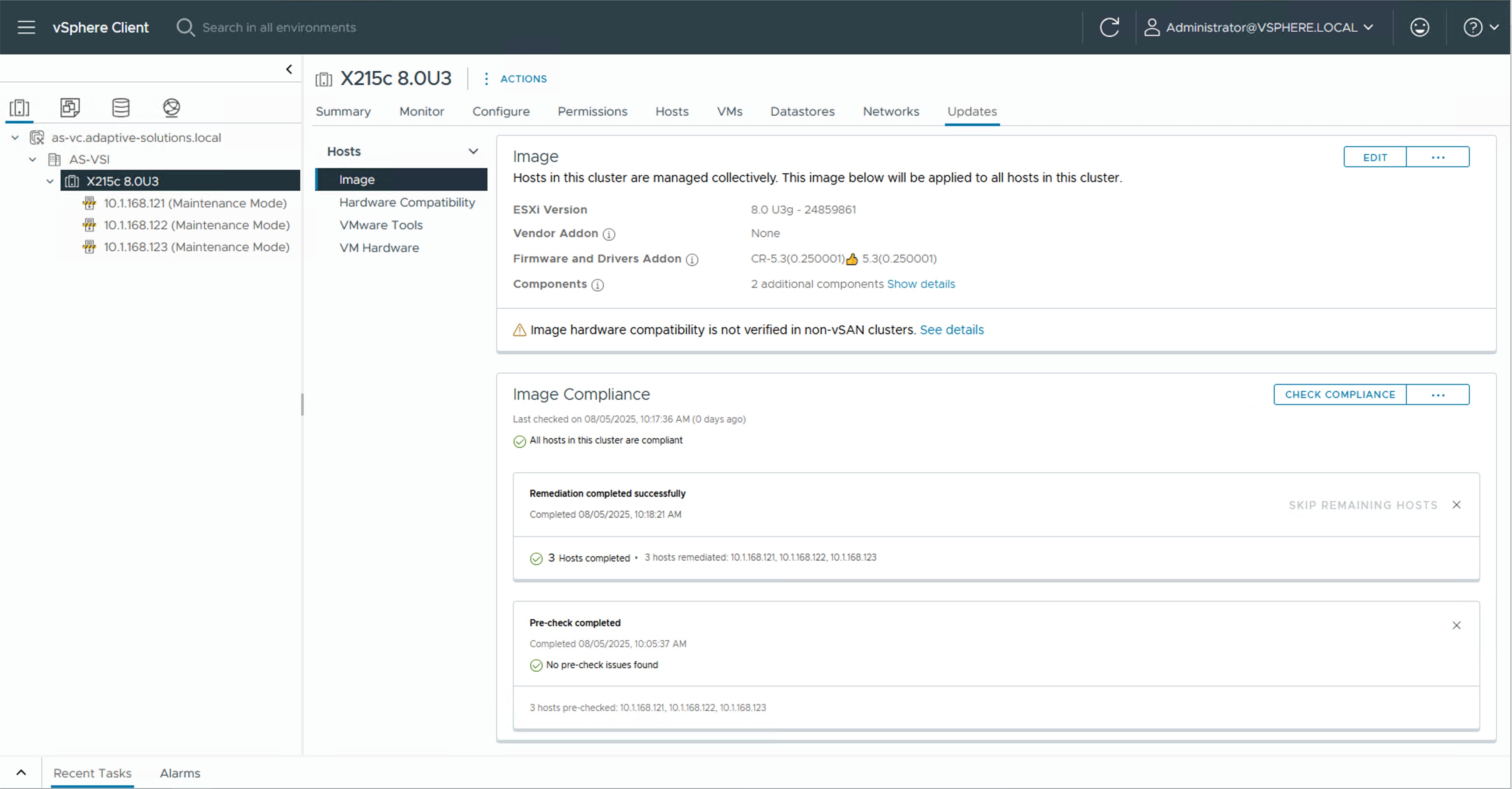
Create vSphere Distributed Switches
Procedure 1. Create VMware vDS for vMotion and Application Traffic
The VMware vDS setup creates the primary vDS for vMotion and Application traffic. To configure the first VMware vDS, follow these steps:
Step 1. Right-click the AS-VSI datacenter and go to Distributed Switch > New Distributed Switch…
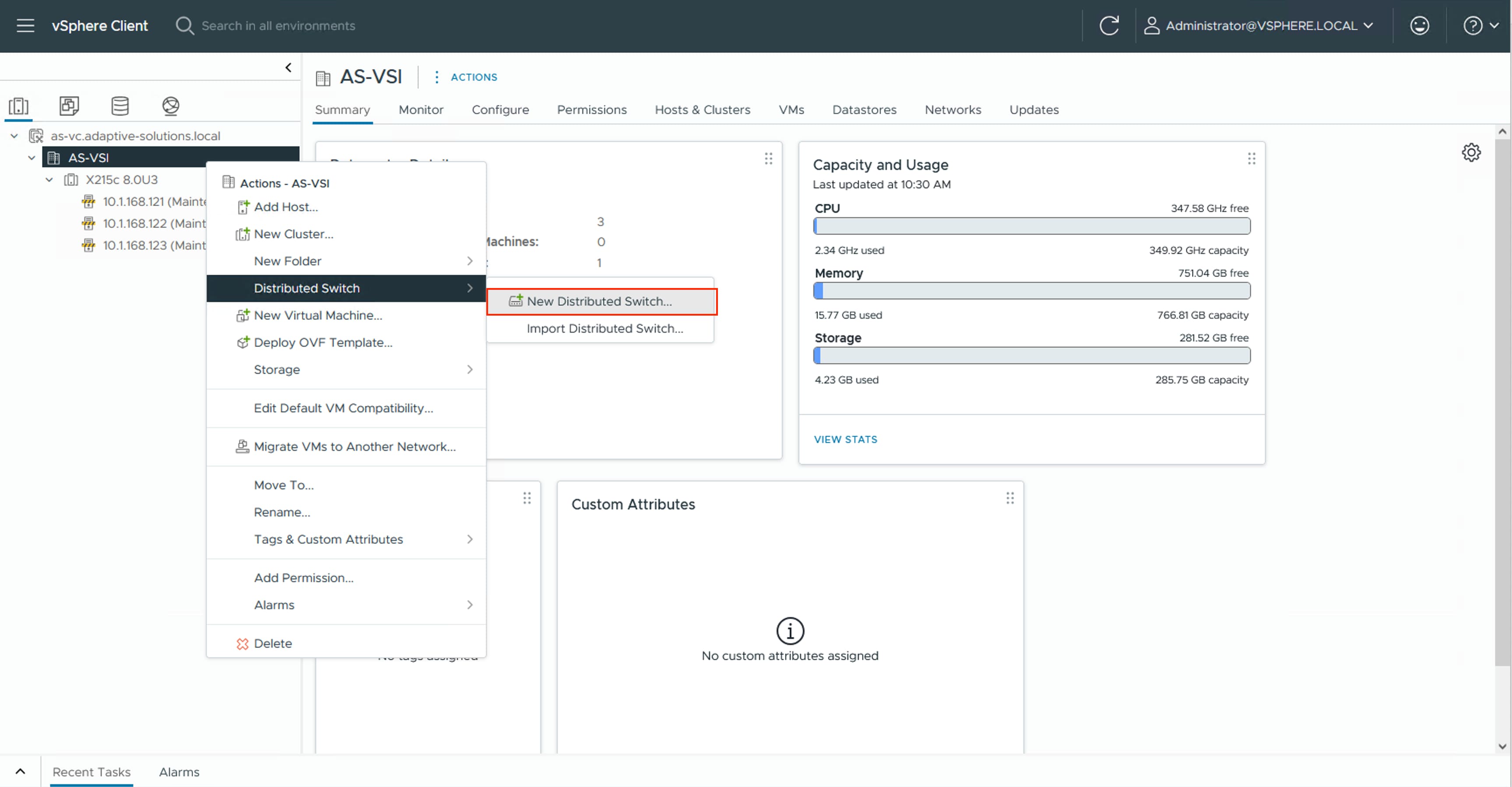
Step 2. Provide a name for the distributed switch “vDS0” in this example and click NEXT.
Step 3. Leave 8.0.3 selected for the distributed switch version and click NEXT.
Step 4. Lower the Number of uplinks from 4 to 2 and provide a Port group name for the default port group to align with the Application traffic. Click NEXT.
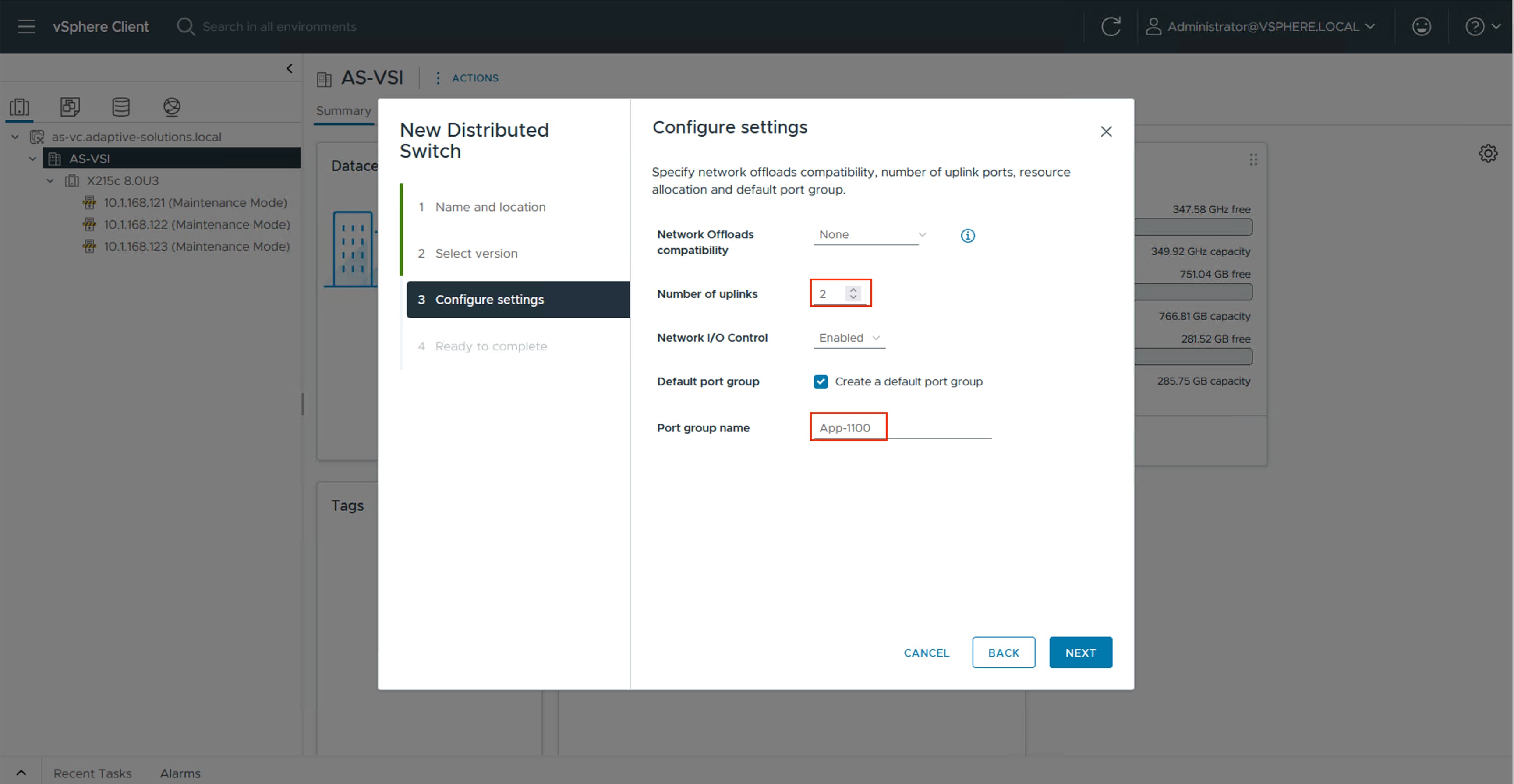
Step 5. Review the settings for the distributed switch and click FINISH.
Step 6. Click the Networking icon and right-click the newly created distributed switch. Under Actions go to Settings > Edit Settings… .
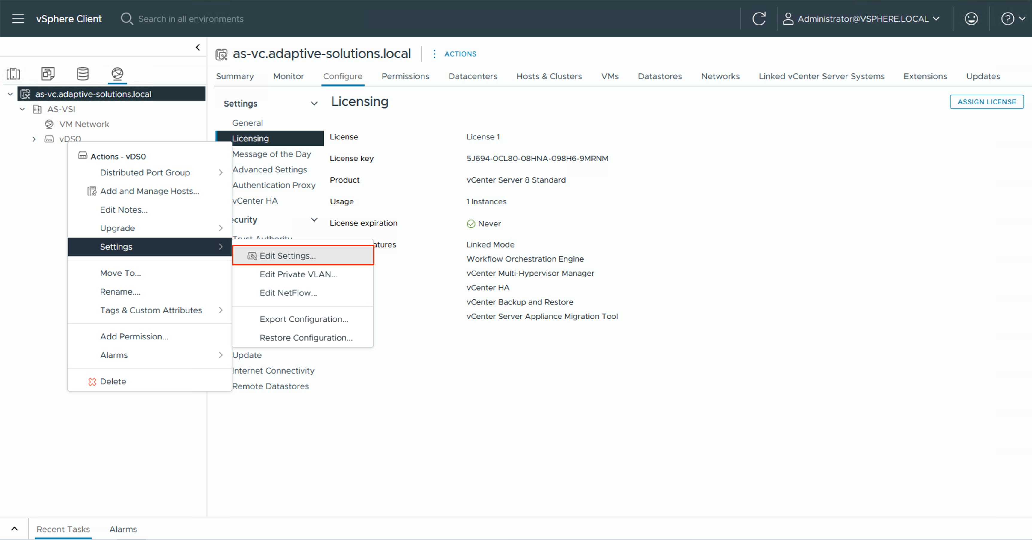
Step 7. Select the Advanced tab and change the MTU from 1500 to 9000. Click OK.
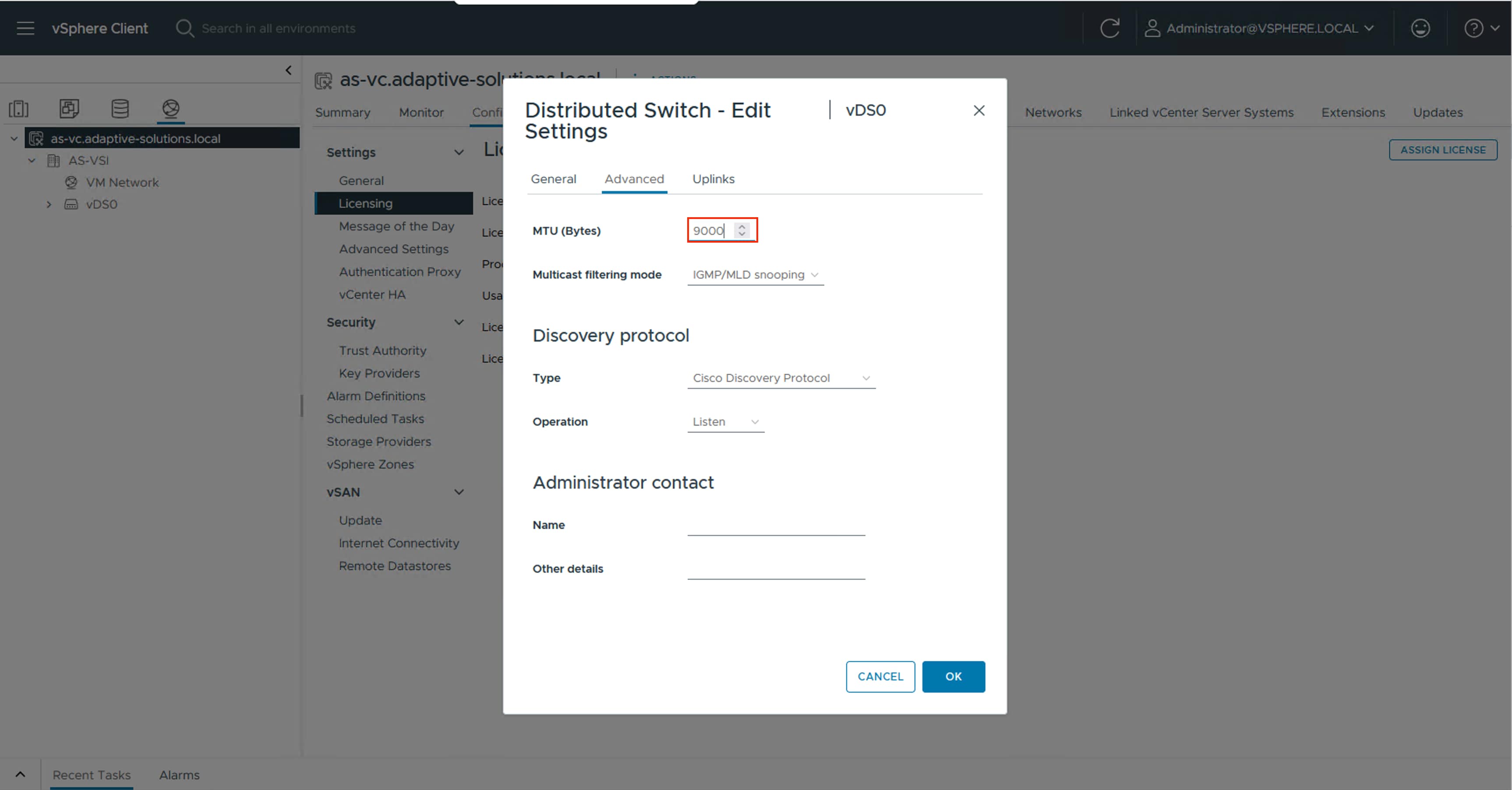
Procedure 2. Create a vMotion Distributed Port Group
Step 1. Right-click the newly created distributed switch. From Actions, go to Distributed Port Group > New Distributed Port Group… .
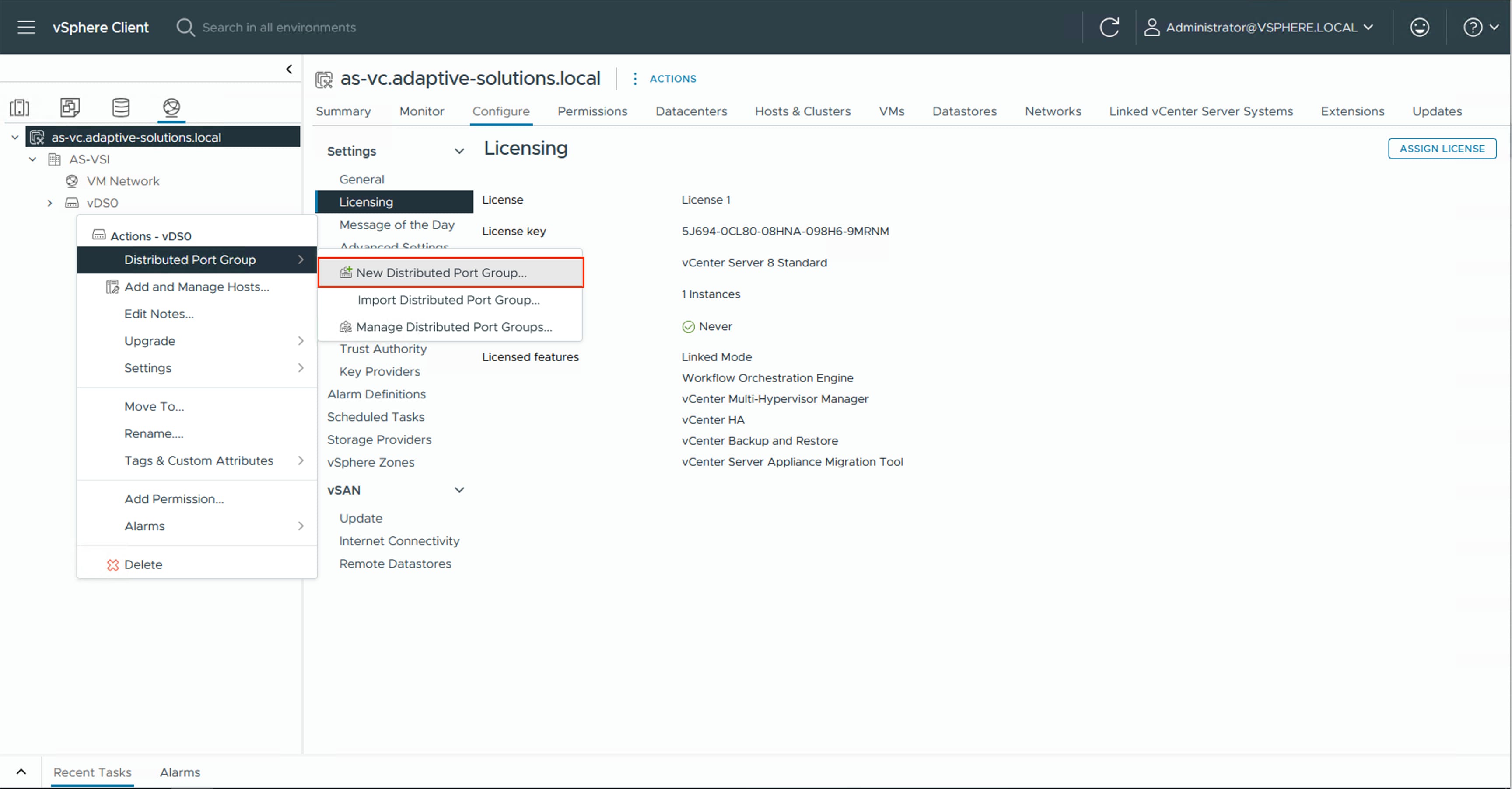
Step 2. Provide a name for the vMotion distributed port group and click NEXT.
Step 3. Select VLAN from the VLAN type drop-down list and specify the appropriate VLAN for vMotion. Check the box for Customize default policies configuration and click NEXT.
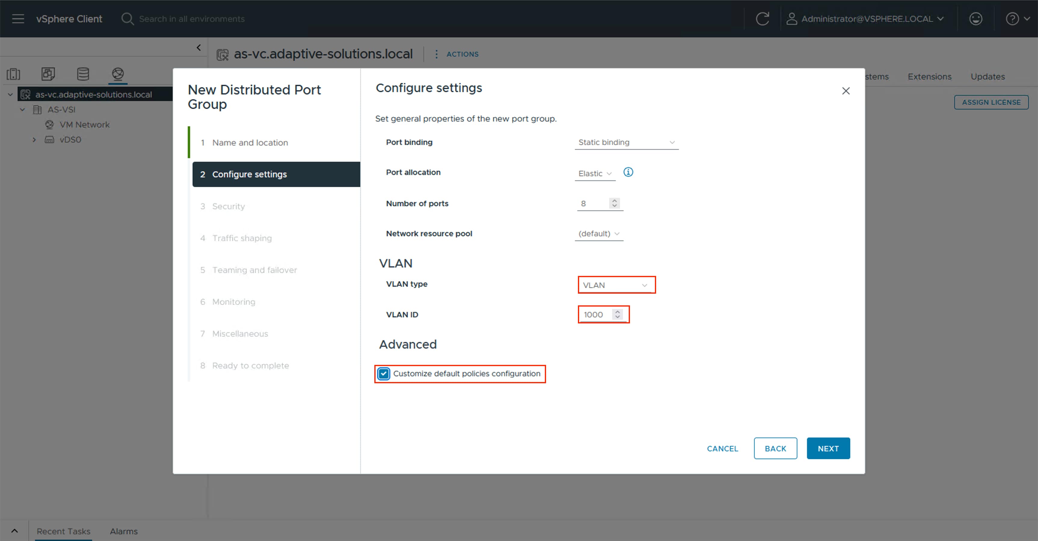
Step 4. Click NEXT through the Security and Traffic shaping dialogue screens.
Step 5. In Teaming and failover, select Uplink 1 and click MOVE DOWN twice to have it set as a standby link. Click NEXT.
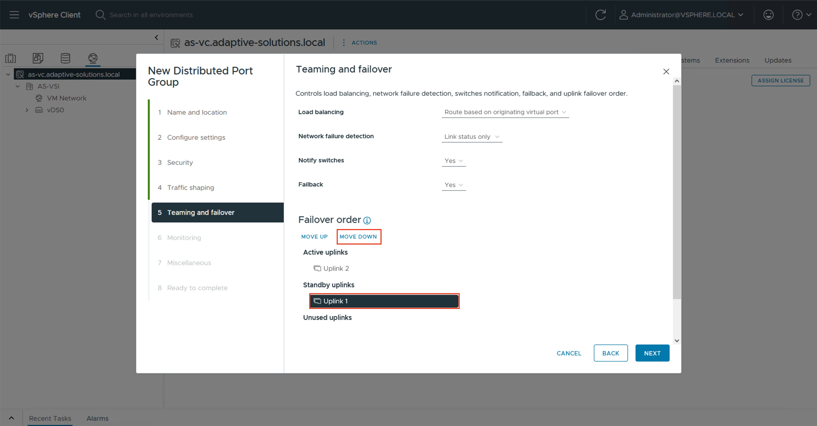
Note: Uplink 2 is made active for this Distributed Port Group, with Uplink 1 as standby to force the vMotion traffic to stay within the B side of the UCS fabric during normal operation, preventing it from having to hairpin up into the Nexus to switch between fabrics.
Step 6. Click NEXT through the Monitoring and Miscellaneous dialogue screens, review the settings presented within Ready to complete, and click FINISH to create the distributed port group.
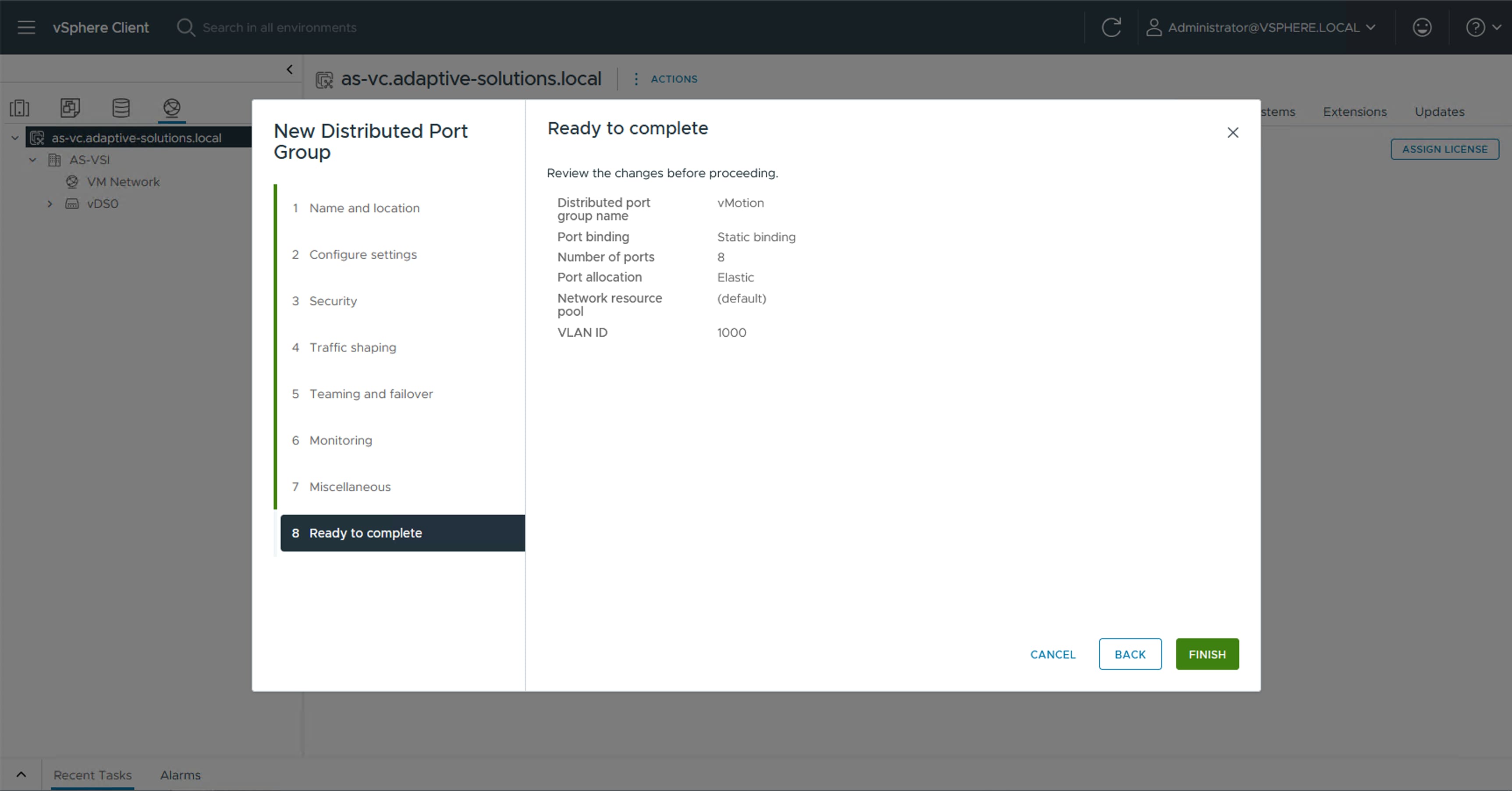
Step 7. Repeat steps 1-6 for each VM application network taking note of desired teaming and failover, leaving both uplinks active if there is no path priority.
Procedure 3. Create VMware vDS for IP Storage
The VMware vDS setup will create a single vDS for NVMe/TCP.
Step 1. Right-click the AS-VSI datacenter and go to Distributed Switch > New Distributed Switch… .
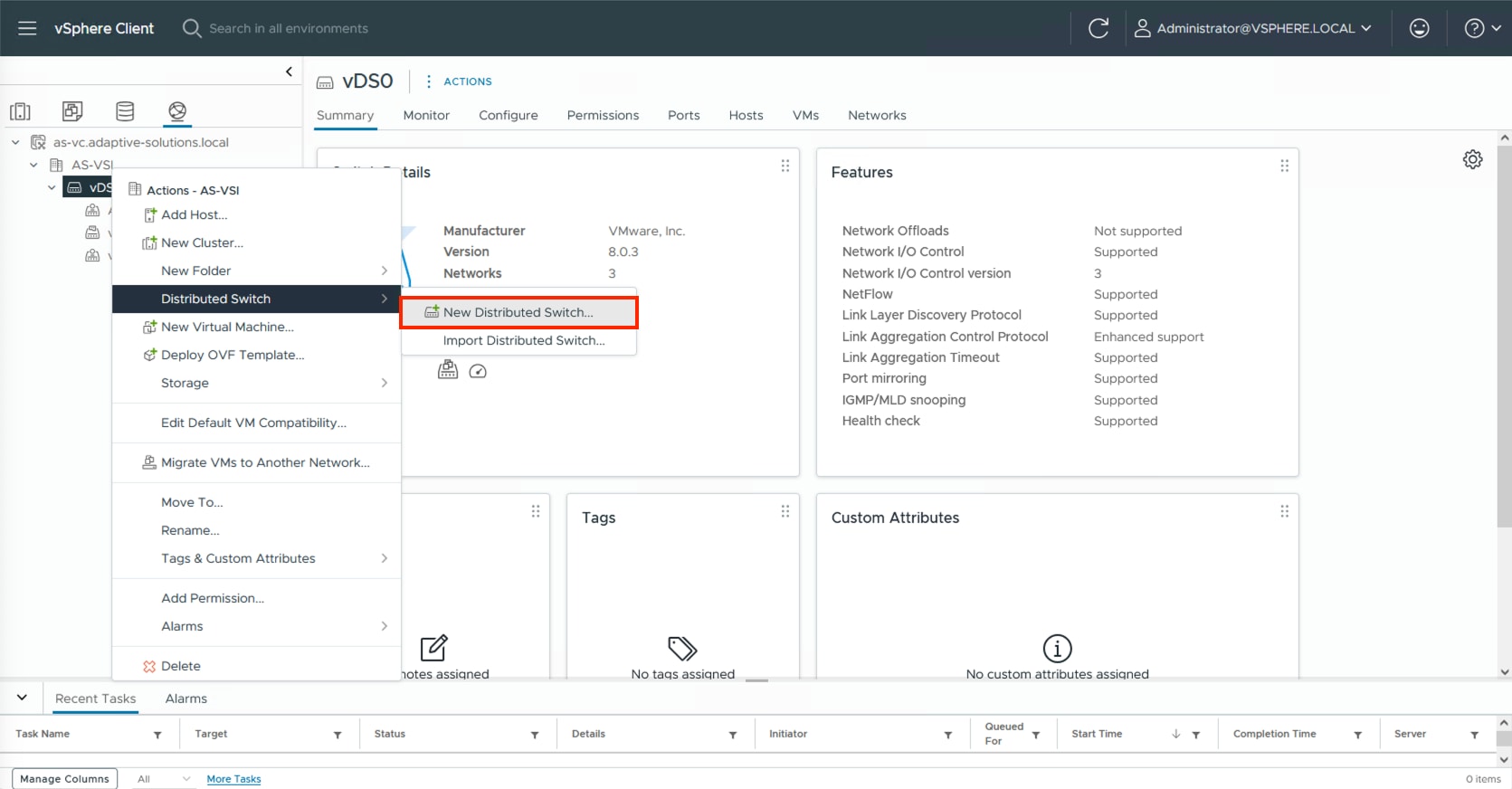
Step 2. Provide a name for the distributed switch and click NEXT.
Step 3. Leave 8.0.3 selected for the distributed switch version and click NEXT.
Step 4. Lower the Number of uplinks from 4 to 2 and deselect the checkbox for Default port group. Click NEXT.
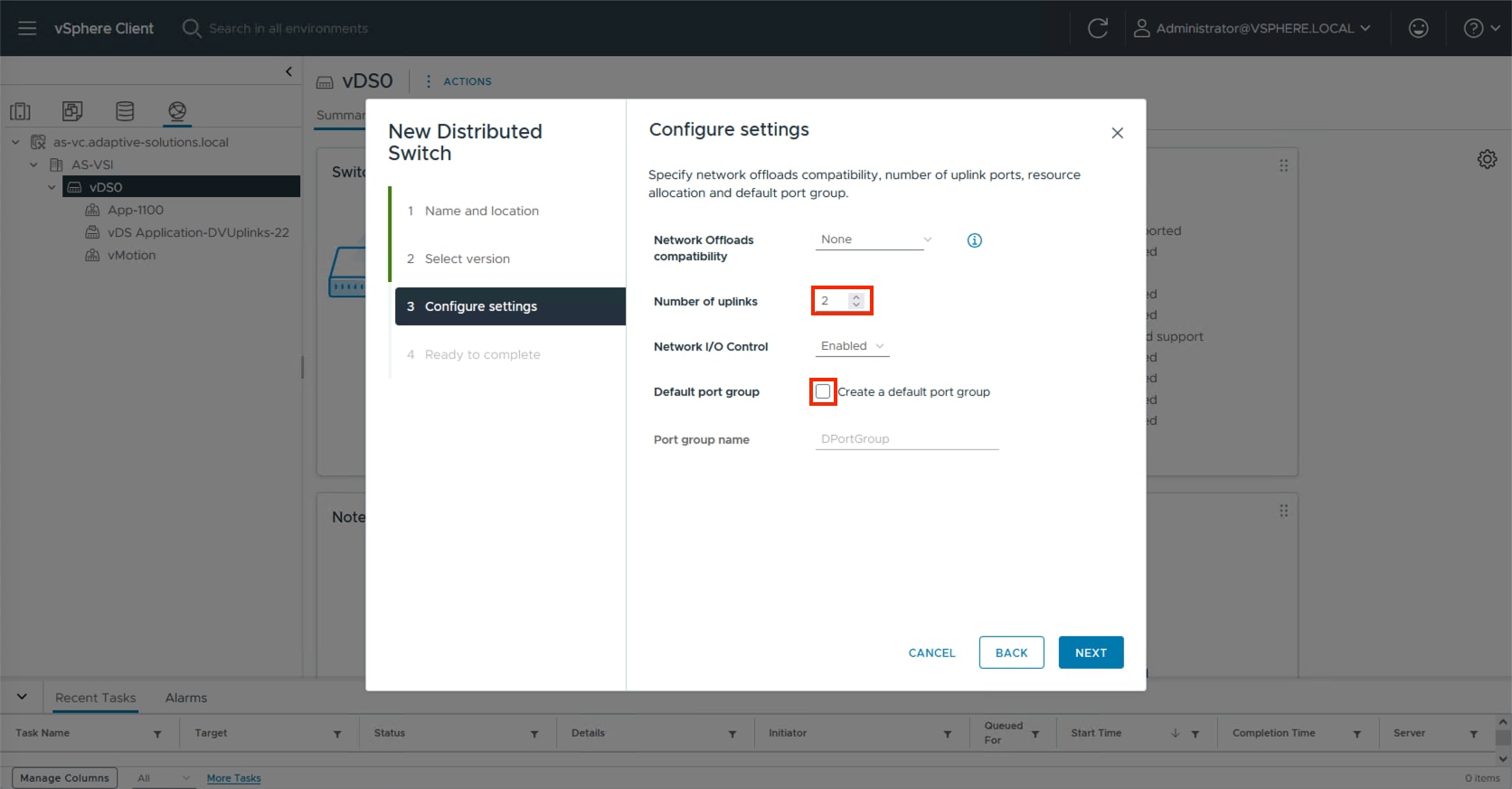
Step 5. Review the settings for the distributed switch and click FINISH.
Step 6. Click the Networking icon and right-click the newly created distributed switch. Under Actions go to Settings > Edit Settings… .
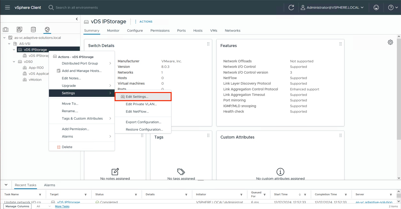
Step 7. Click the Advanced tab and change the MTU from 1500 to 9000. Click OK.
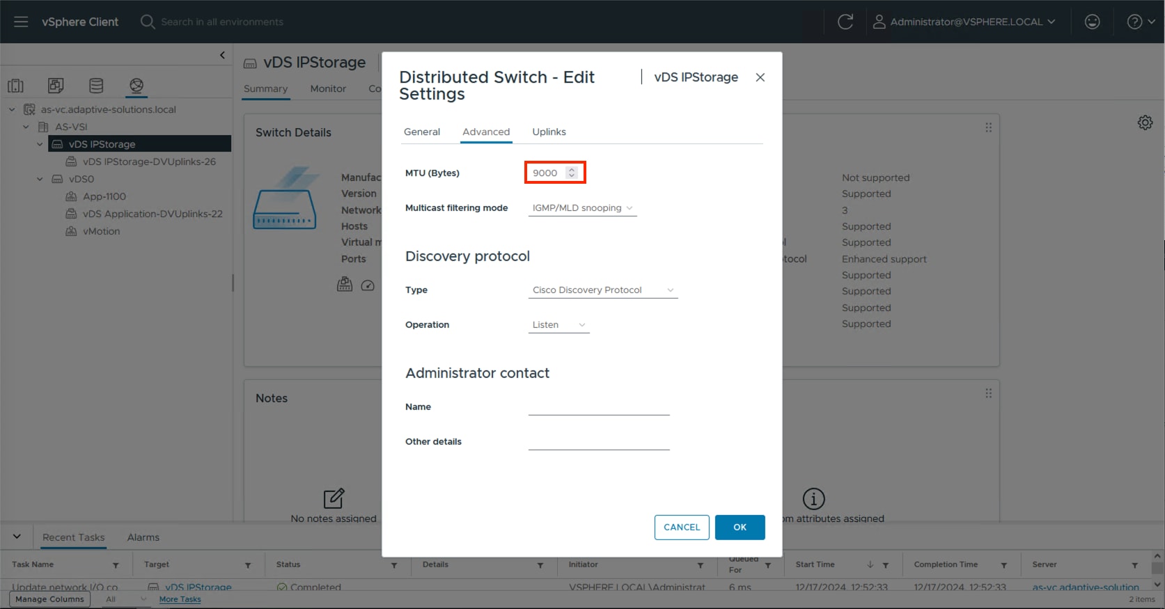
Procedure 4. Create the NVMe/TCP Distributed Port Groups
This procedure creates two distributed port groups for the NVMe/TCP traffic, one for each side of the fabric, with the appropriate vmnic uplink associated to the port group.
Step 1. Right-click the newly created distributed switch. In Actions, go to Distributed Port Group > New Distributed Port Group… .
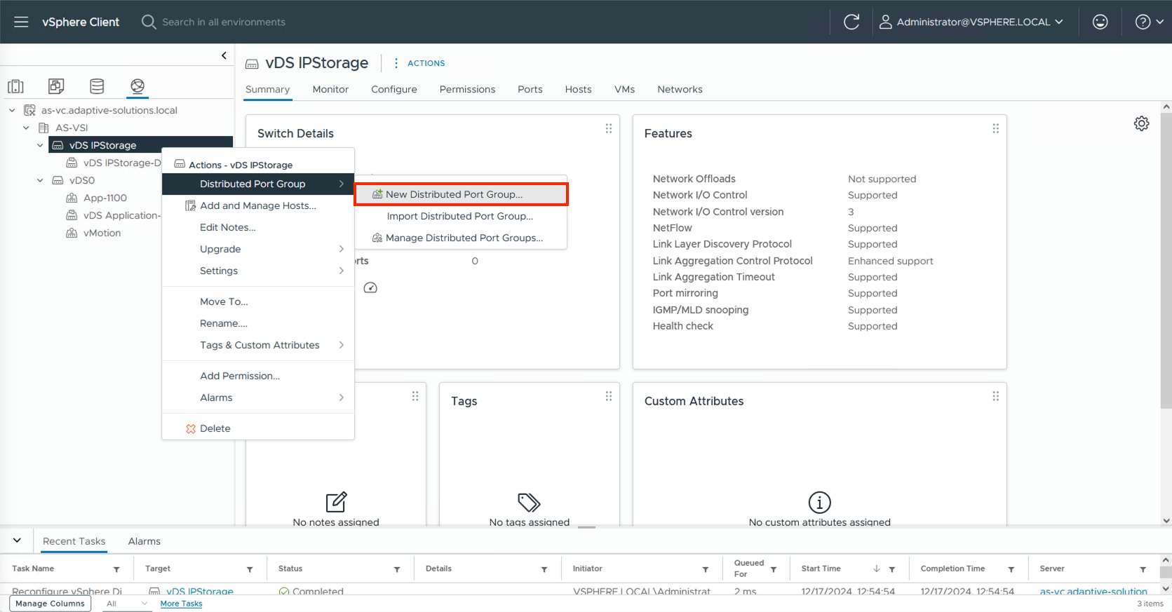
Step 2. Provide a name for the NVMe/TCP-A distributed port group and click NEXT.
Step 3. Select VLAN from the VLAN type drop-down list and specify the appropriate VLAN for NVMe/TCP-A. Check the box for Customize default policies configuration and click NEXT.
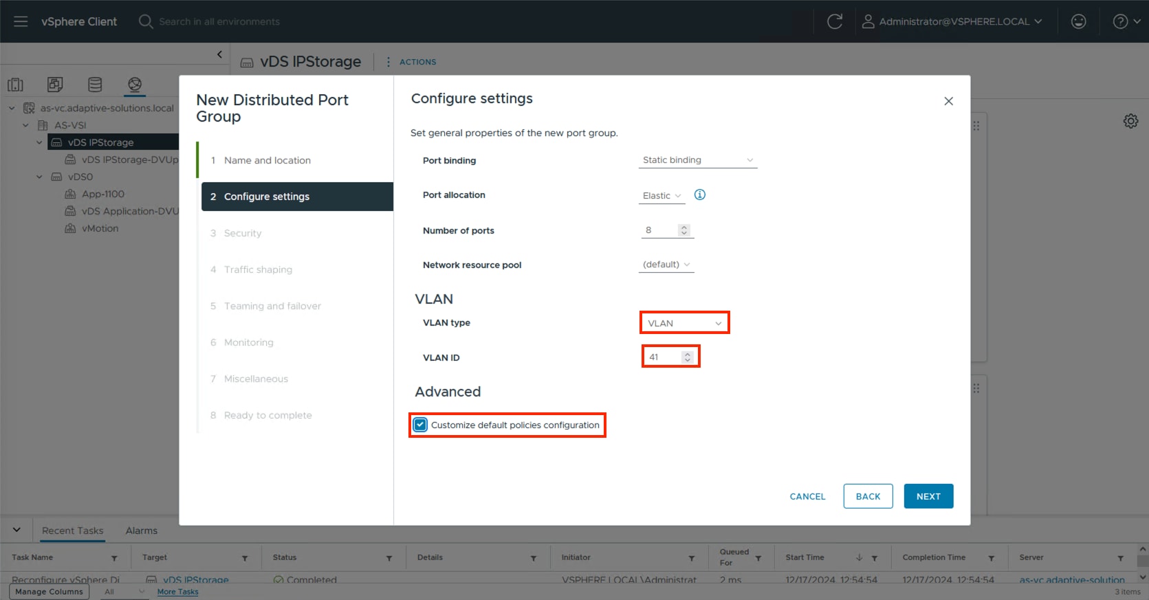
Step 4. Click NEXT through the Security and Traffic shaping dialogue screens.
Step 5. In Teaming and failover, select Uplink 2 and click MOVE DOWN twice to have it set as an unused link. Click NEXT.
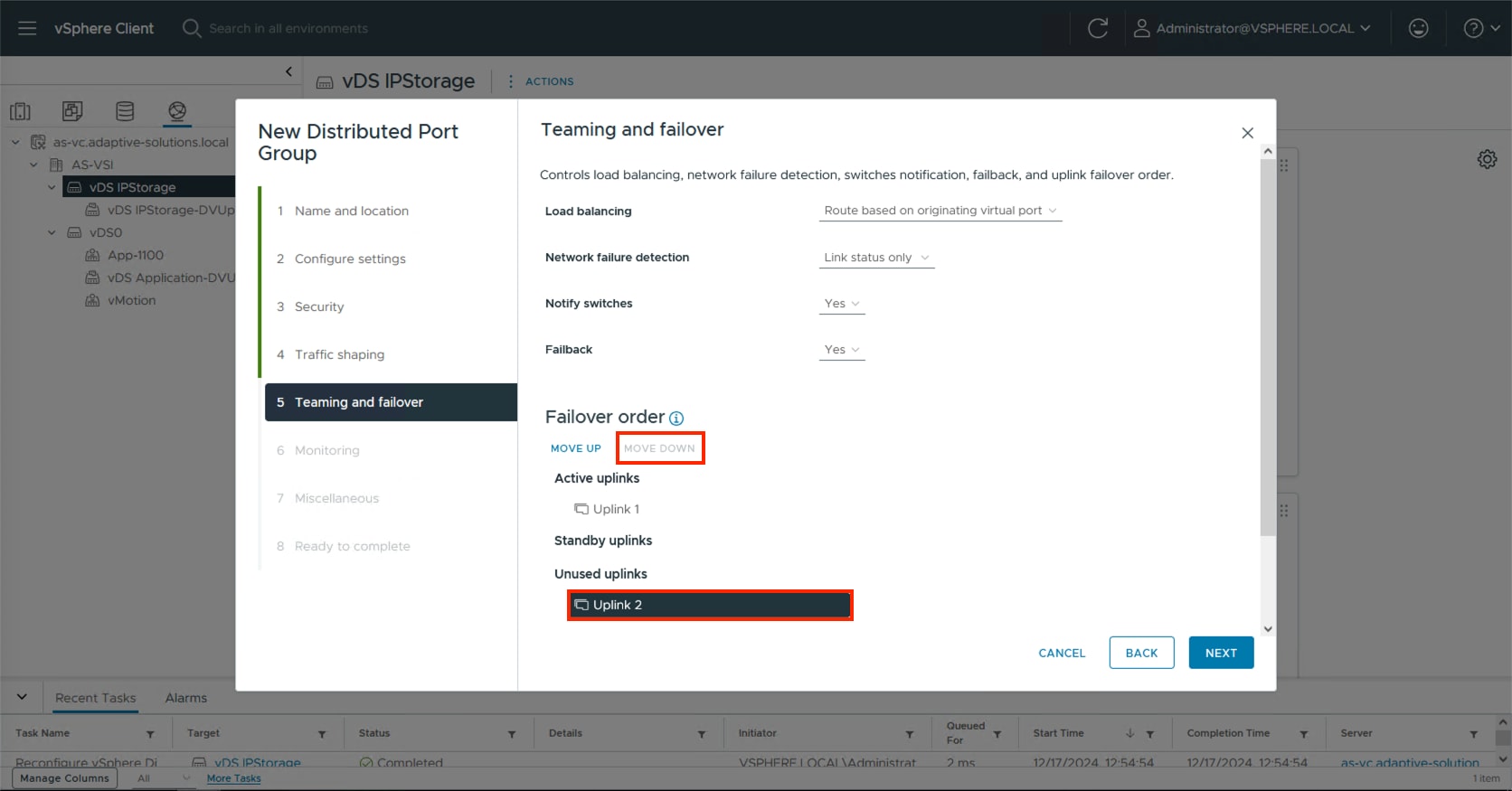
Step 6. Click NEXT through the Monitoring and Miscellaneous dialogue screens, review the settings presented within Ready to complete and click FINISH to create the distributed port group.
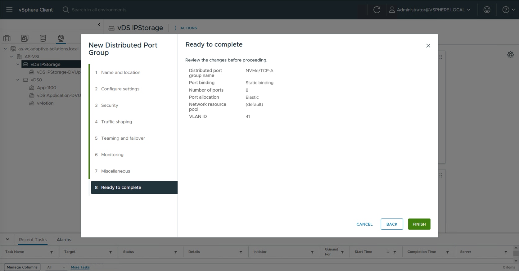
Step 7. Repeat steps 1-6 for the NVMe/TCP-B network, setting the appropriate VLAN (42), configuring Uplink 2 as the active uplink and Uplink 1 as an unused uplink.
Procedure 5. Add ESXi hosts to the primary vDS
Step 1. Select the application distributed virtual switch, right-click it and select the Add and Manage Hosts… option.
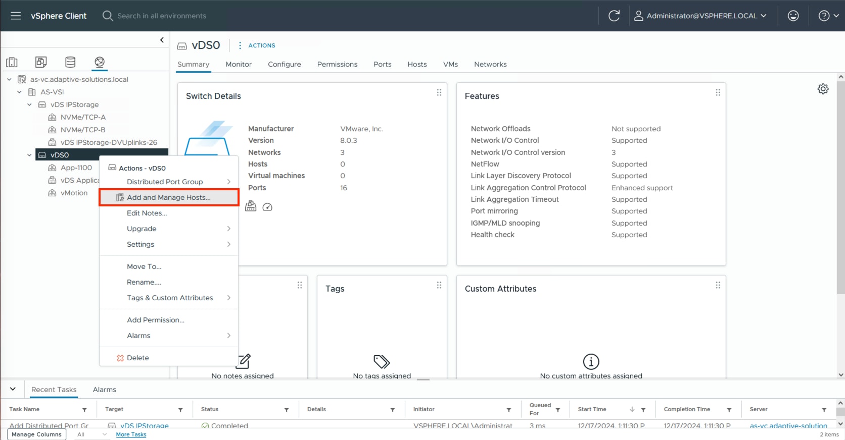
Step 2. Leave Add hosts selected and click NEXT.
Step 3. Click the SELECT ALL checkbox, or some subset of hosts to be added to vCenter and click NEXT.
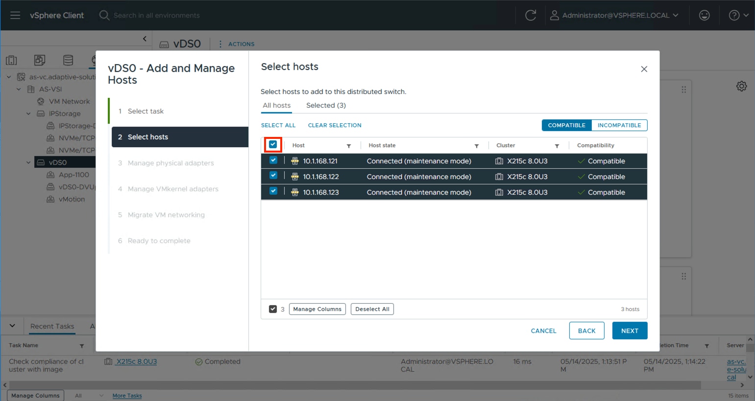
Step 4. Specify vmnic2 to be Uplink 1 and vmnic3 to be Uplink 2 and click NEXT.
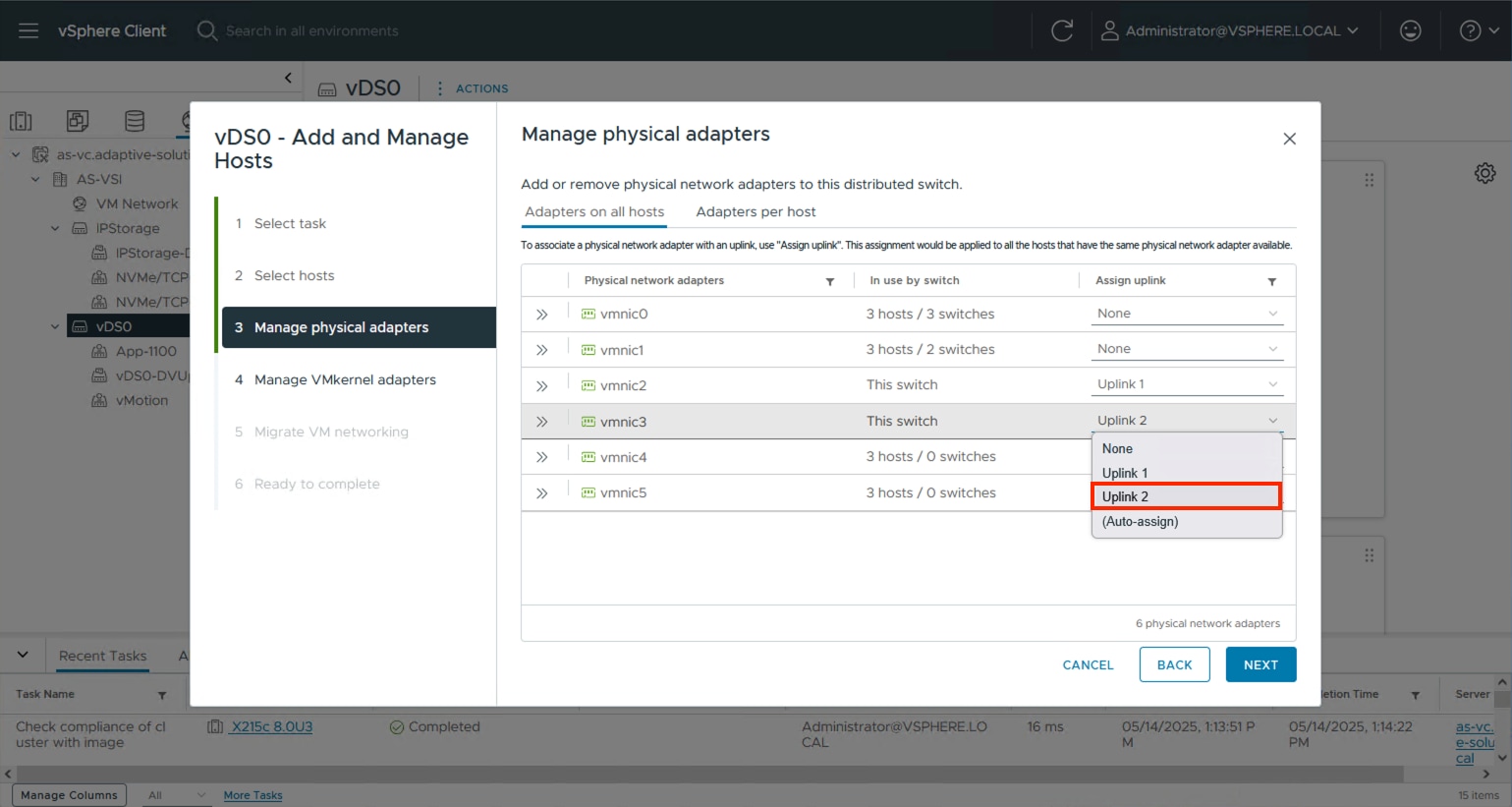
Step 5. Click NEXT past the Manage VMkernel adapters and Migrate VM networking dialogue screens. Review the summary within the Ready to complete screen and click FINISH.
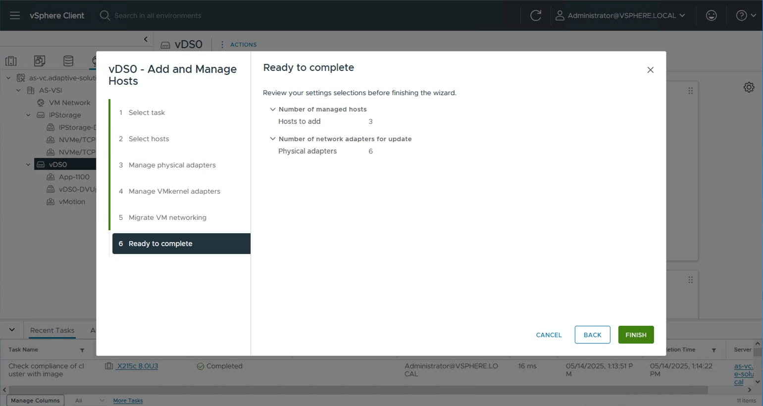
Procedure 6. Add ESXi hosts to the IP Storage vDS
Step 1. Select the IP Storage distributed virtual switch, right-click it and select the Add and Manage Hosts… option.
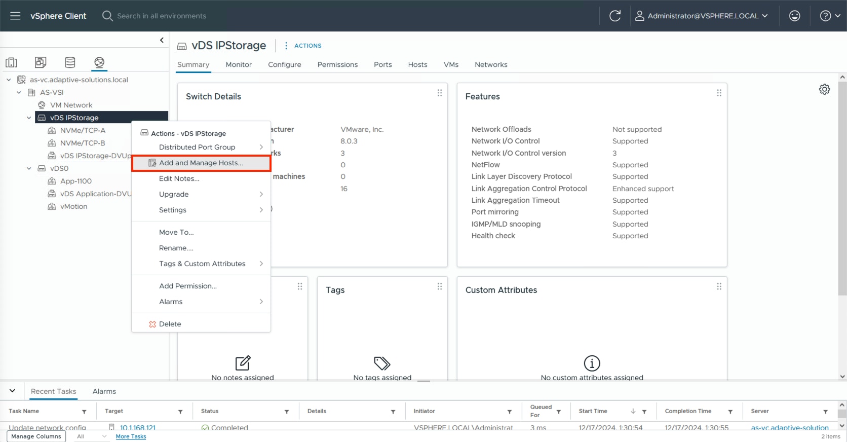
Step 2. Leave Add hosts selected and click NEXT.
Step 3. Click the SELECT ALL checkbox or some subset of hosts to be added to vCenter and click NEXT.
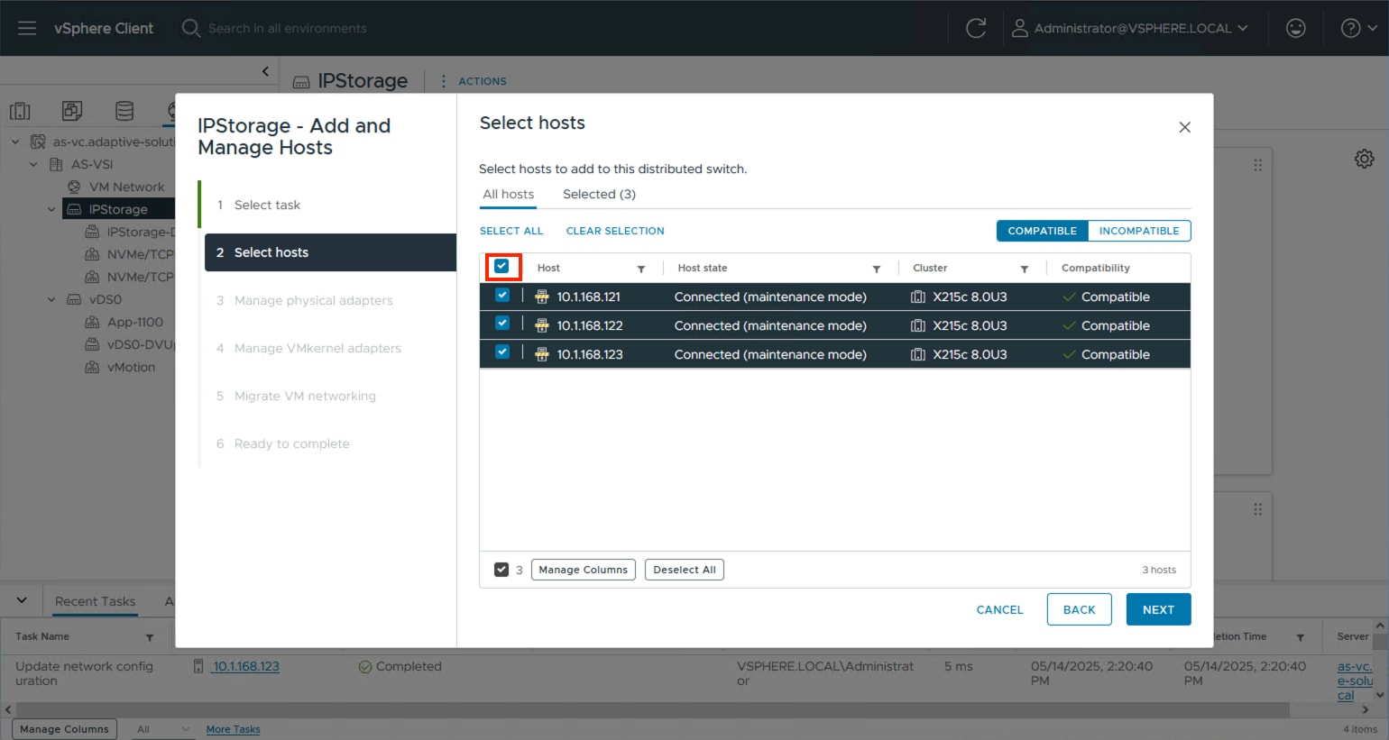
Step 4. Specify vmnic4 to be Uplink 1 and vmnic5 to be Uplink 2 and click NEXT.
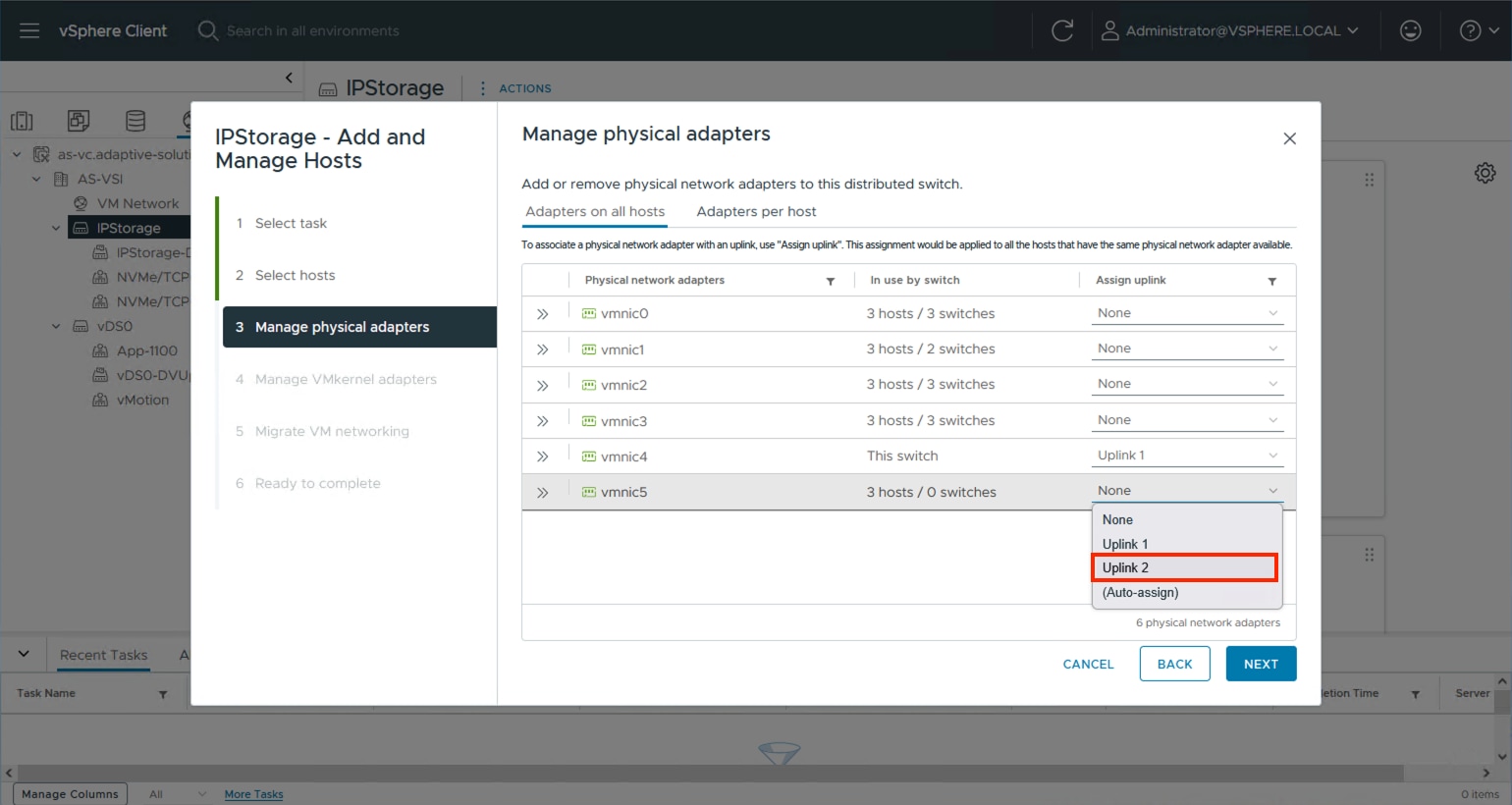
Step 5. Click NEXT past the Manage VMkernel adapters and Migrate VM networking dialogue screens. Review the summary within the Ready to complete screen and click FINISH.
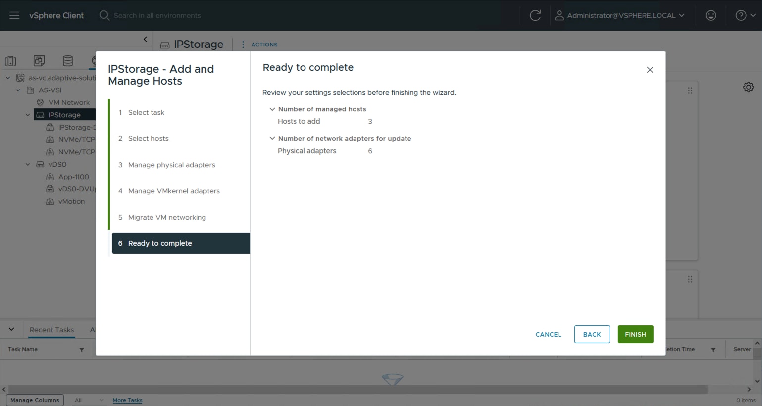
Procedure 7. Add vMotion vmkernel to the ESXi hosts
Step 1. Select the vMotion distributed port group from the primary vDS, right-click it and select the Add VMkernel Adapters… option.
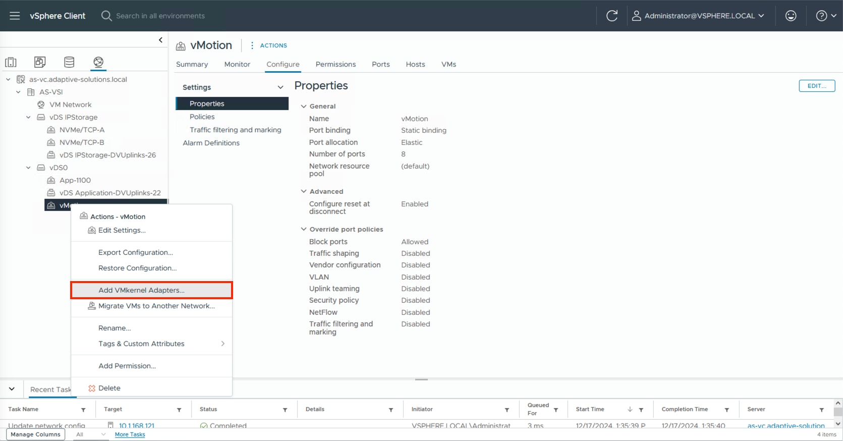
Step 2. Select all ESXi hosts and click NEXT.

Step 3. Select vMotion from the TCP/IP stack drop-down list. Click NEXT.
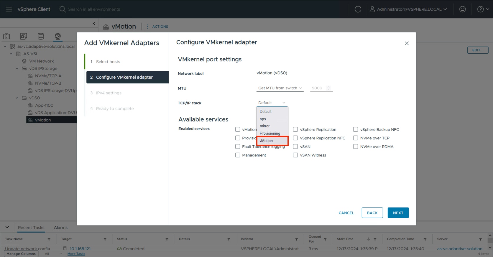
Step 4. Select Use static IPV4 settings and provide an IP and netmask appropriate for the vMotion network to the VMkernels. Click NEXT.
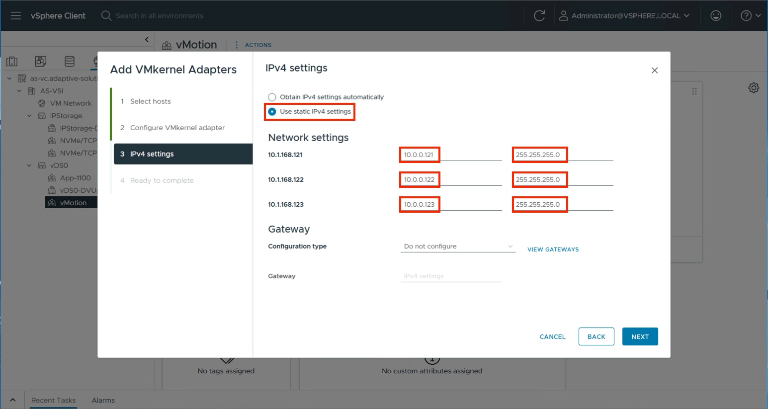
Step 5. Review the summary within Ready to complete and click FINISH.
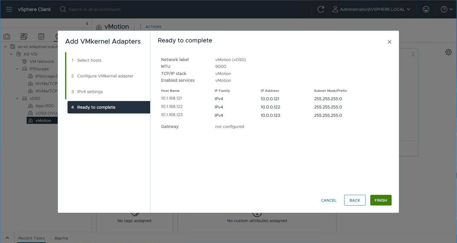
Procedure 8. Add NVMe/TCP VMkernels to the ESXi hosts
Step 1. Select the NVMe/TCP-A distributed port group from the IP Storage vDS, right-click it and select the Add VMkernel Adapters… option.
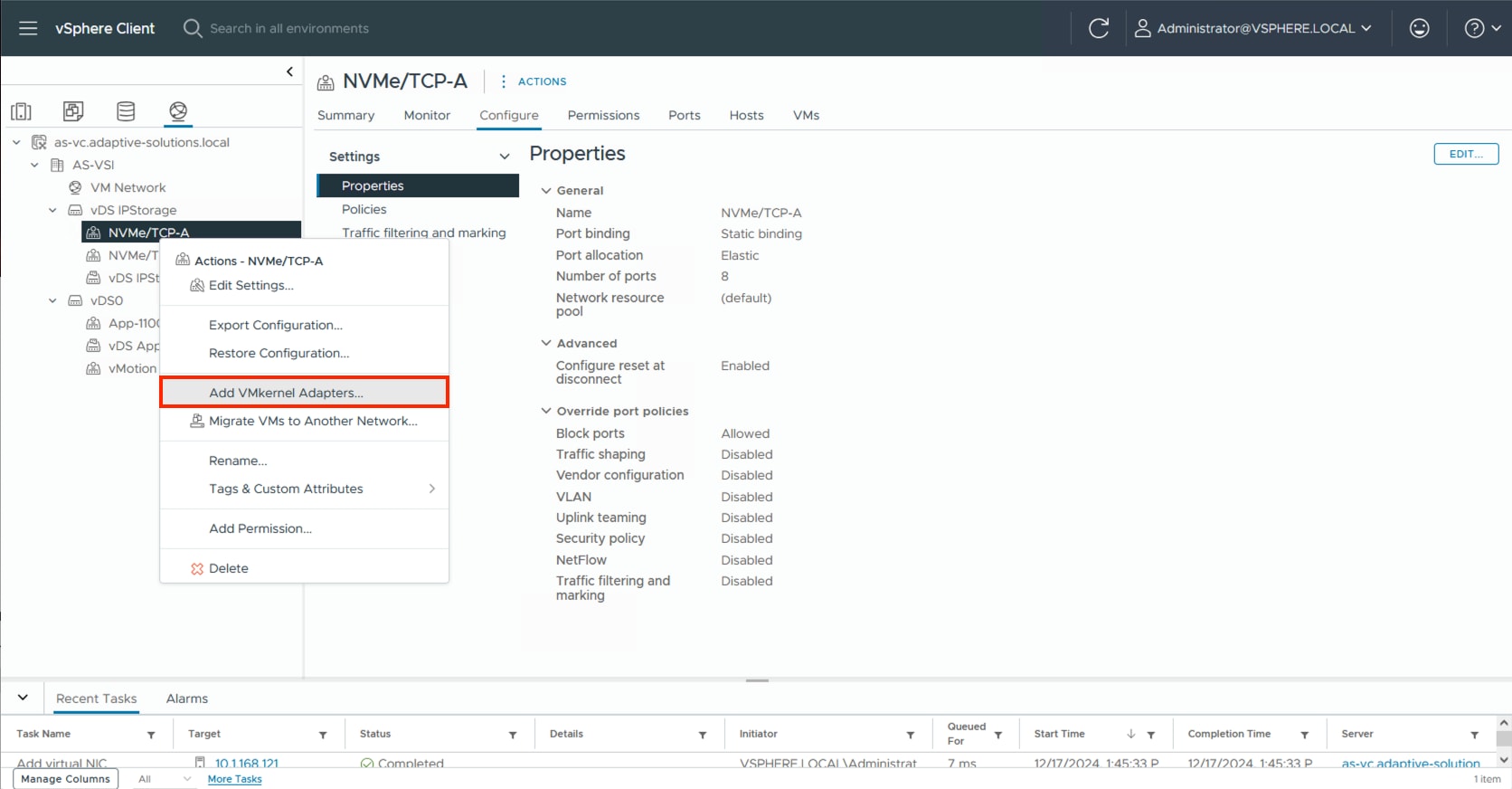
Step 2. Click SELECT ALL and click NEXT.
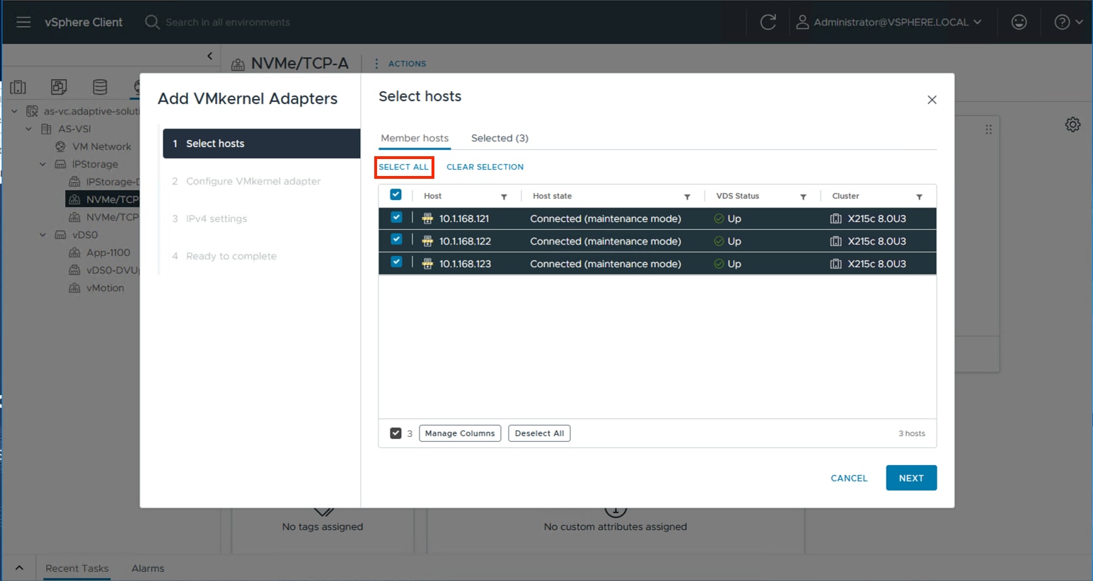
Step 3. Leave TCP/IP stack set to Default and click the NVMe over TCP option in Enabled services. Click NEXT.
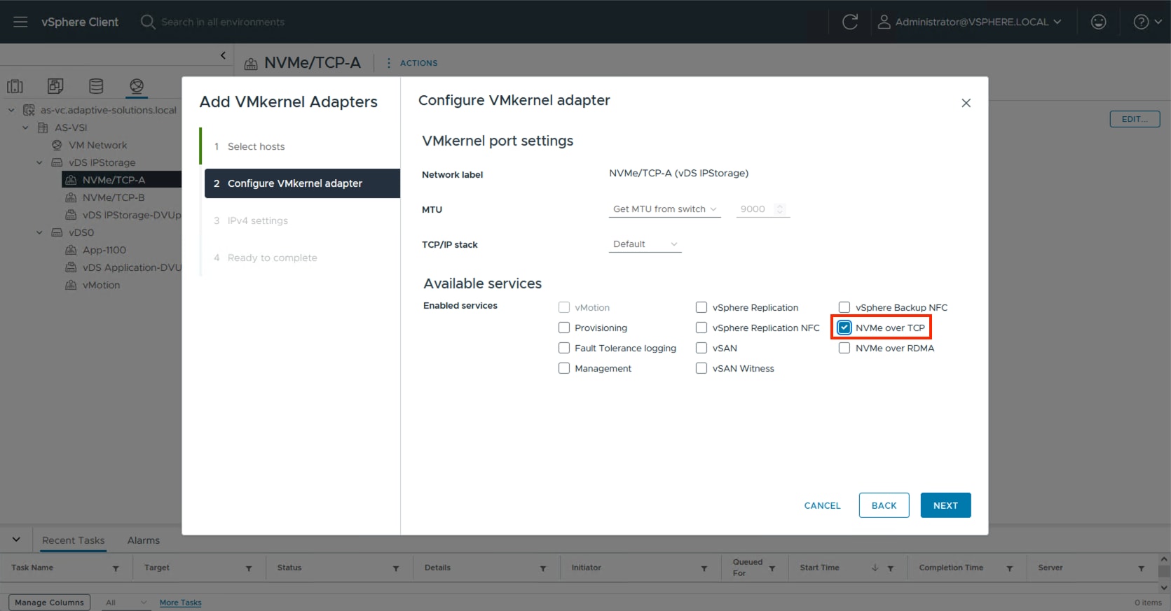
Step 4. Select Use static IPV4 settings and provide an IP and netmask appropriate for the NVMe/TCP-A network to the VMkernels. Click NEXT.
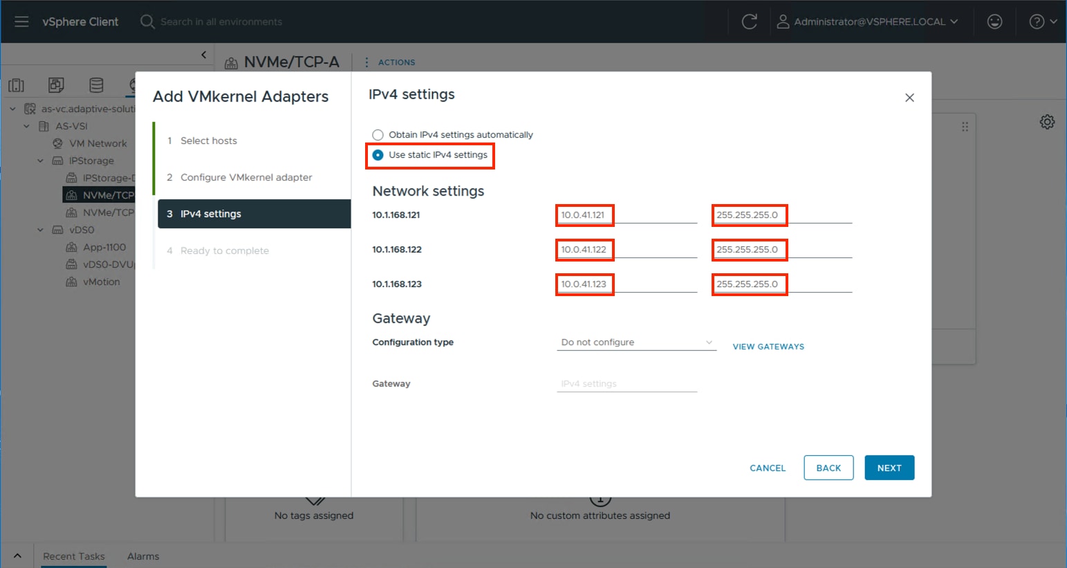
Step 5. Review the summary within Ready to complete and click FINISH.
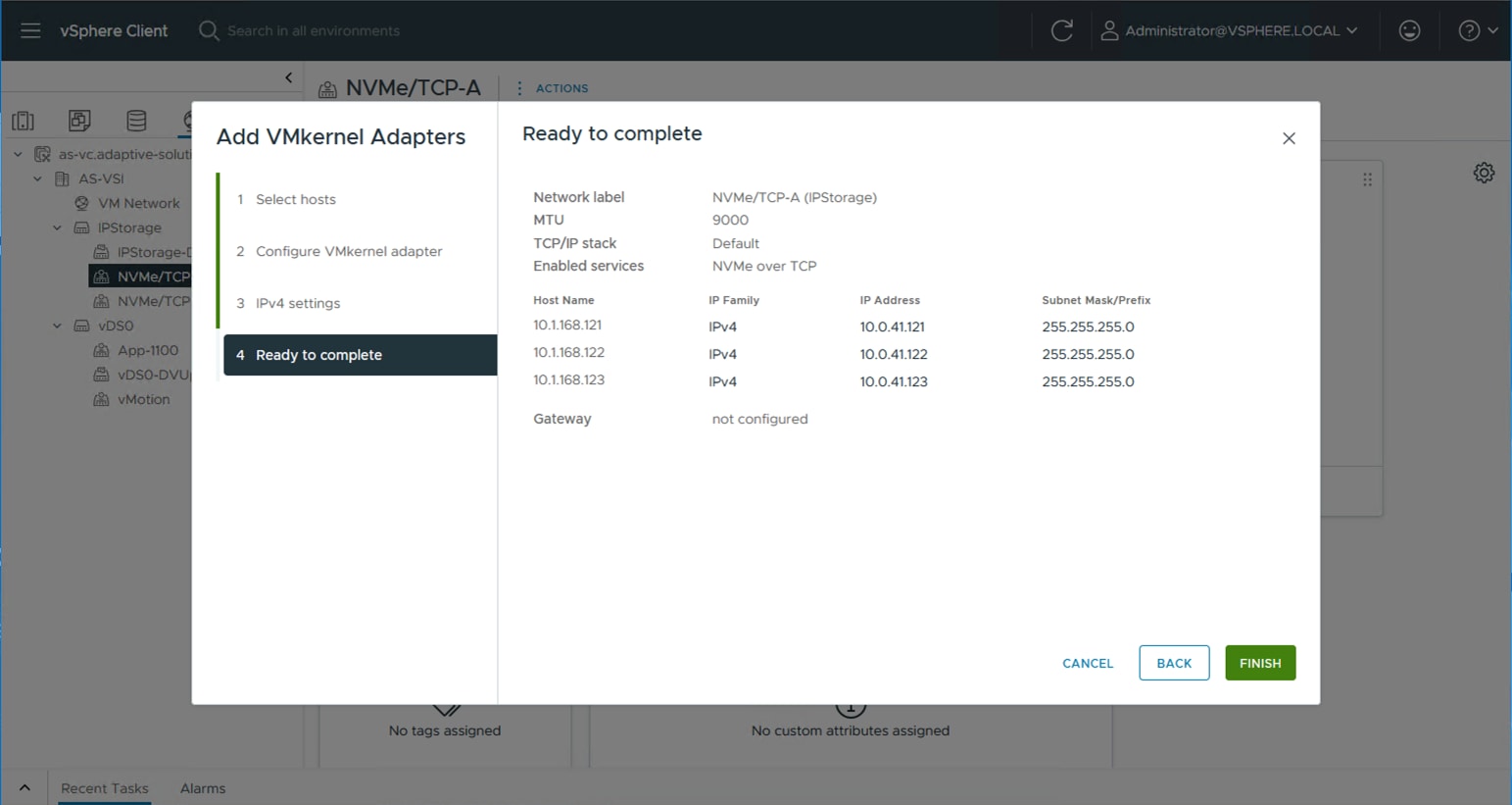
Step 6. Repeat steps 1-5 for the NVMe/TCP-B VMkernel creation.
Additional Settings on ESXi Hosts
Procedure 1. NTP Configuration
Perform the steps in this procedure on all ESXi hosts in the cluster.
Step 1. Click the Hosts and Clusters icon, expand the datacenter and cluster to find the first ESXi host. Go to Configure > System > Time Configuration.
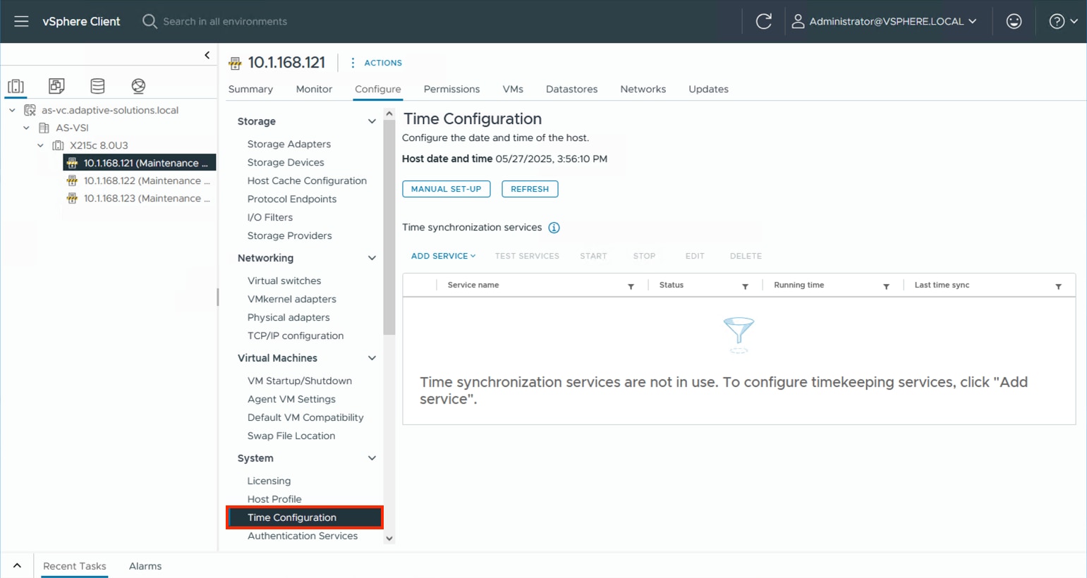
Step 2. Select MANUAL SET-UP if the time is not correct and adjust it. From the ADD SERVICE drop-down list select the Network Time Protocol option.
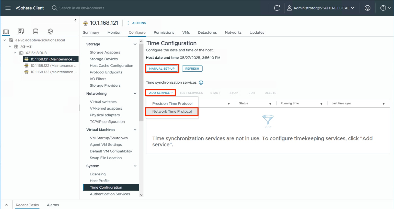
Step 3. Specify the appropriate IP/FQDN(s) for NTP server(s). Click OK.
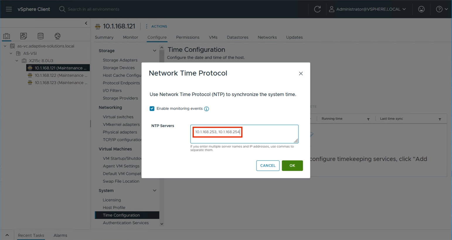
Procedure 2. Configure Host Power Policy
Perform steps in this procedure on all ESXi hosts in the cluster.
Note: Implementation of this policy is recommended in the Performance Tuning Cisco UCS C245 M8 Rack Servers 4th Gen AMD EPYC Processors which will be applicable to UCS X215c M8 servers (based on processor similarities), see: https://www.cisco.com/c/en/us/products/collateral/servers-unified-computing/ucs-c-series-rack-servers/ucs-c245-m8-rack-ser-4th-gen-amd-epyc-pro-wp.html#VMwareESXi for maximum VMware ESXi performance. This policy can be adjusted based on your requirements.
Step 1. From the ESXi host, go to Configure > Hardware > Overview and find Power Management at the bottom of the Overview section. Click EDIT POWER POLICY.
Step 2. Select High performance from the options to maximize performance potential or leave as Balanced depending upon your policy and needs and click OK.
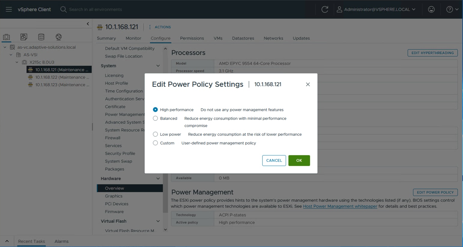
Procedure 3. TPM Encryption Recovery Key Backup
The hosts will have a TPM Encryption Recovery Key Backup Alarm triggered after installation. This key will be needed to restore the host if the TPM key is changed specifically, or the entire underlying server is changed out.
Step 1. From a terminal, connect to the host via ssh and run the following command:
[root@esxi-21:~] esxcli system settings encryption recovery list
Recovery ID Key
-------------------------------------- ---
{F5F6D31F-CA85-4451-A367-CEE6F5DC3A98} 495286-007580-642831-640654-176862-262487-354899-274270-280123-398990-028973-111474-390721-139581-093866-056522
Step 2. Record the Recovery ID and Key as a backup.
Step 3. In vCenter, select the host, and go to Monitor > Issues and Alarms > All Issues.
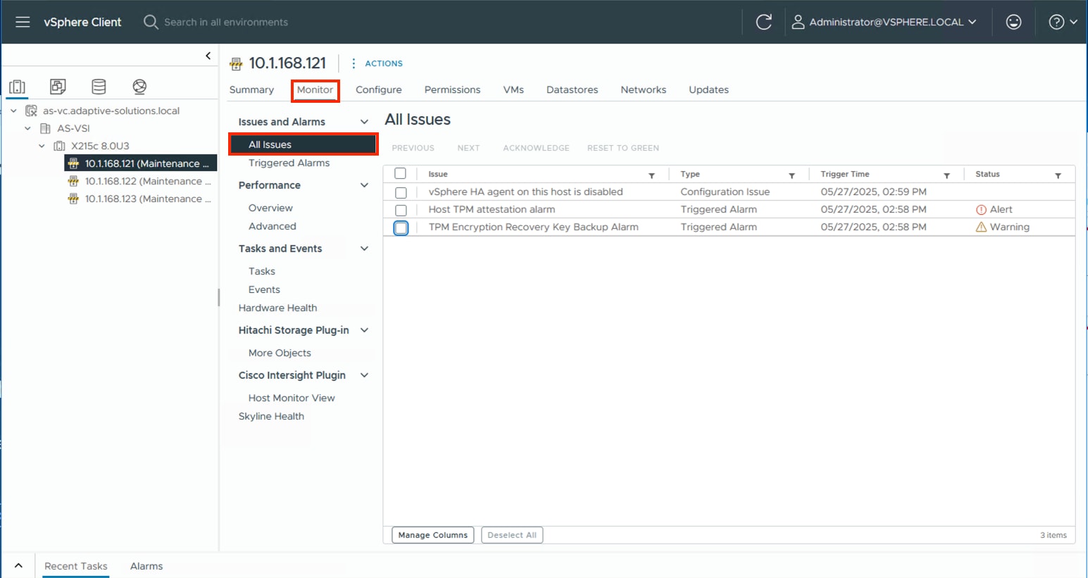
Step 4. Select the TPM Encryption Recovery Key Backup Alarm and click RESET TO GREEN.
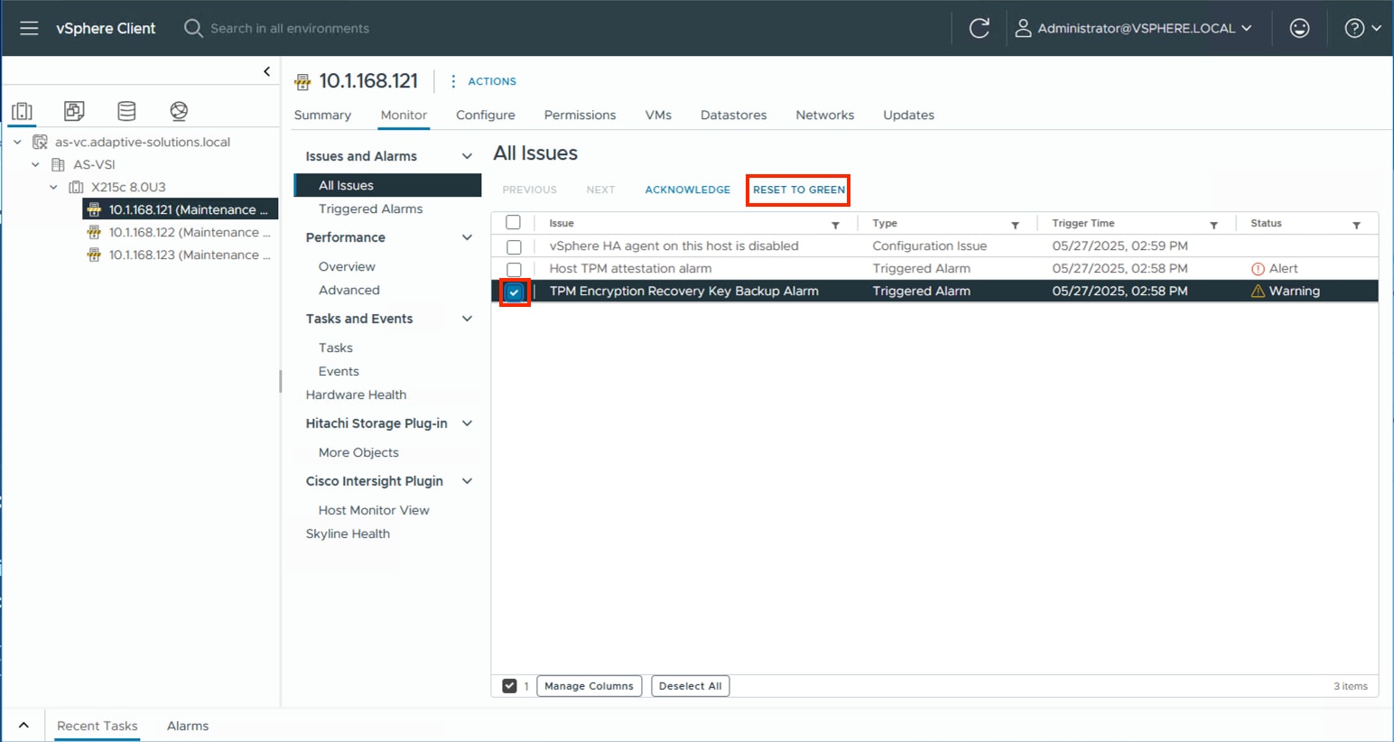
Procedure 4. VMware ESXi 8.0U3 TPM Attestation
If your Cisco UCS servers have Trusted Platform Module (TPM) 2.0 modules installed, the TPM can provide assurance that ESXi has booted with UEFI Secure Boot enabled and using only digitally signed code. In the Cisco Intersight Managed Mode Configuration chapter of this document, UEFI secure boot was enabled in the boot order policy. A server can boot with UEFI Secure Boot with or without a TPM 2.0 module. If it has a TPM, VMware vCenter can attest that the server booted with UEFI Secure Boot. To verify the VMware ESXi 8.0U3 TPM Attestation, follow these steps:
Note: For Cisco UCS servers that have TPM 2.0 modules installed, TPM Attestation can be verified within vCenter.
Step 1. In the vCenter under Hosts and Clusters select the cluster.
Step 2. Click the Monitor tab.
Step 3. Go to Monitor > Security. The Attestation status will show the status of the TPM:
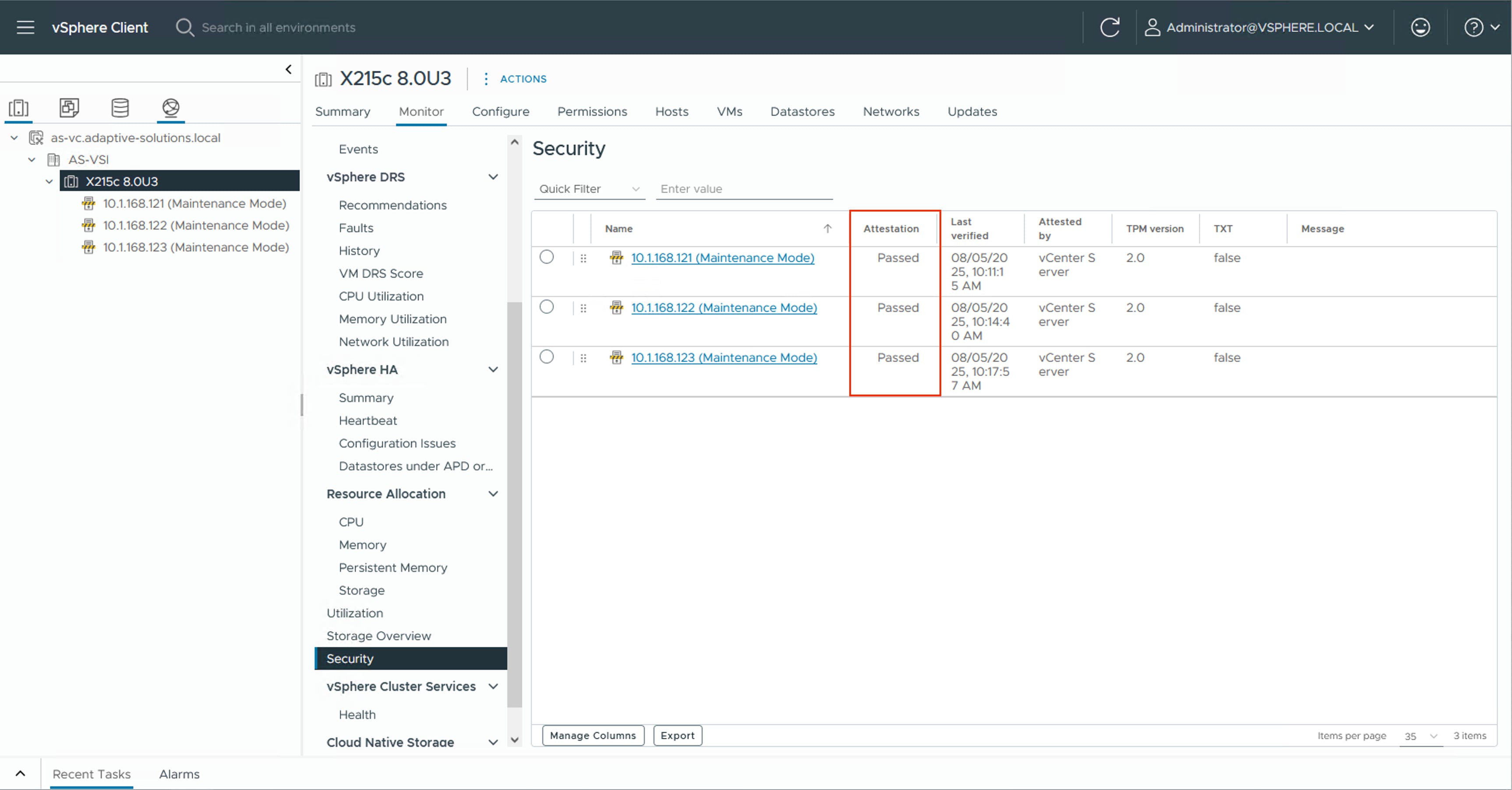
Note: It may be necessary to disconnect and reconnect or reboot a host from vCenter to get it to pass attestation the first time.
Procedure 5. (Optional) Configure Distributed Power Management (DPM)
This procedure details how to configure the host to be able to be shut down during low cluster utilization times to reduce power.
The CIMC Management interface associated with the DPM BMC MAC address will need to be gathered from the Fabric Interconnect Device Console CLI, either from direct console connection, or via ssh.
To gather the CIMC Management interface MAC addresses, complete the following steps:
Step 1. Connect to either Fabric Interconnect Device Console as admin:
% ssh admin@192.168.168.31
Cisco UCSX Direct 9100 Series Fabric Interconnect
admin@192.168.168.31's password:
UCS Intersight Management
AA24-9108-A#
Step 2. Connect to the CIMC Debug Firmware Utility Shell of the first server (connect cimc <chassis>/<blade slot>) from which to collect information:
AA24-9108-A# connect cimc 1/1
Entering character mode
Escape character is '^]'.
CIMC Debug Firmware Utility Shell [ ]
[ help ]#
Step 3. Run the network command and identify the first server MAC (HWaddr) address for the eth0 value from the top of the output that returns:
[ help ]# network
eth0 Link encap:Ethernet HWaddr 9E:38:18:6A:63:69
inet6 addr: fe80::9c38:18ff:fe6a:6369/64 Scope:Link
UP BROADCAST RUNNING MULTICAST MTU:1500 Metric:1
RX packets:18994827 errors:0 dropped:751 overruns:0 frame:0
TX packets:14774318 errors:0 dropped:0 overruns:0 carrier:0
collisions:0 txqueuelen:1000
RX bytes:18446744072442813521 (16777215.9 TiB) TX bytes:286039526 (272.7 MiB)
Interrupt:50
Step 4. Type exit and repeat steps 2 and 3 for each server.
Note: With the information gathered for each server to configure, continue with the following steps:
Step 5. From the first host that has been added, go to Configure > System > Power Management and click EDIT… .
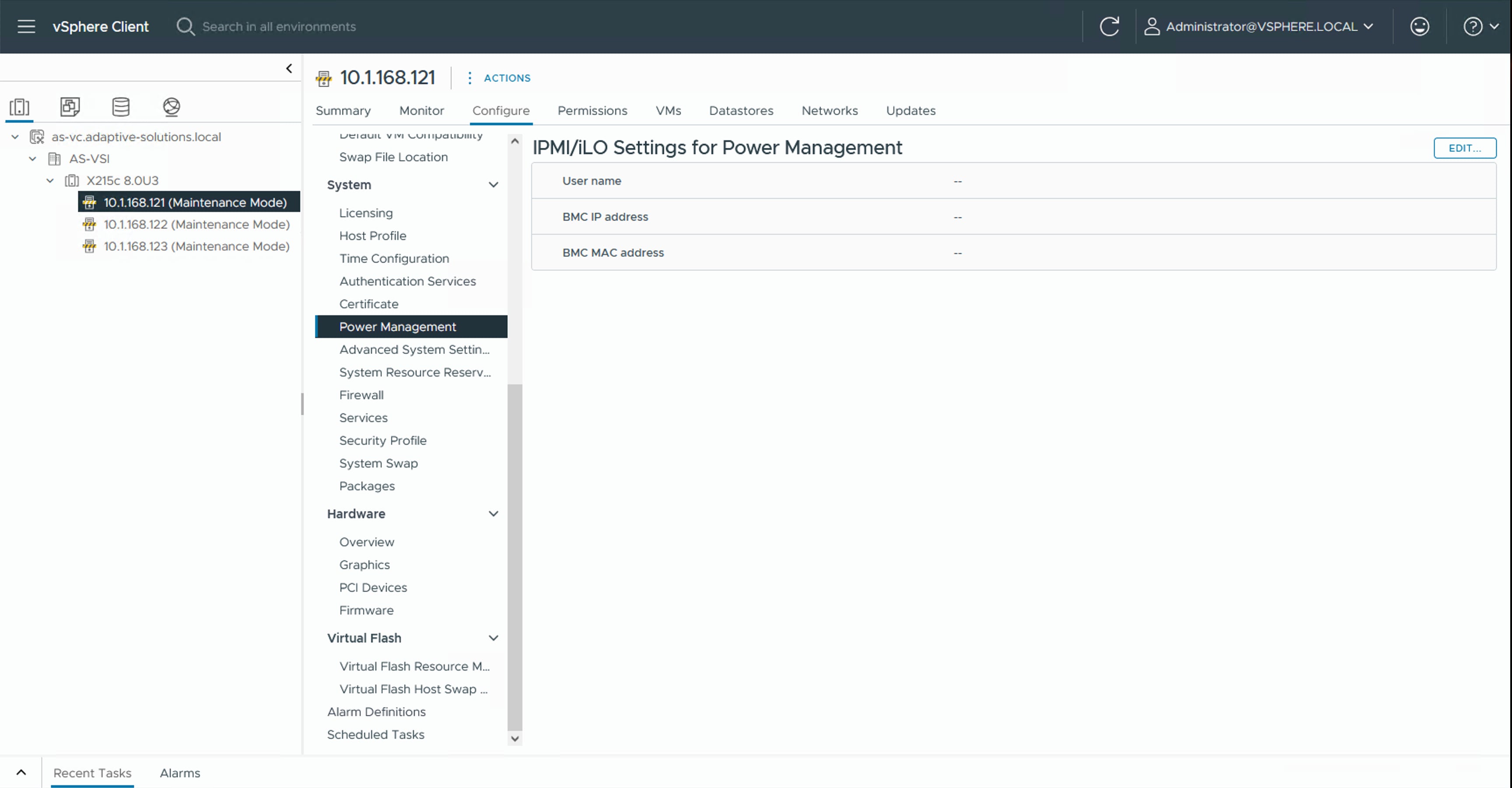
Step 6. Provide the credentials for a local user with admin privileges within the UCS domain, the assigned KVM Management IP from Intersight (Servers [select server]> Management Controller > Management Access > Management IP), and the CIMC MAC address previously collected from the Fabric Interconnect Device Console.
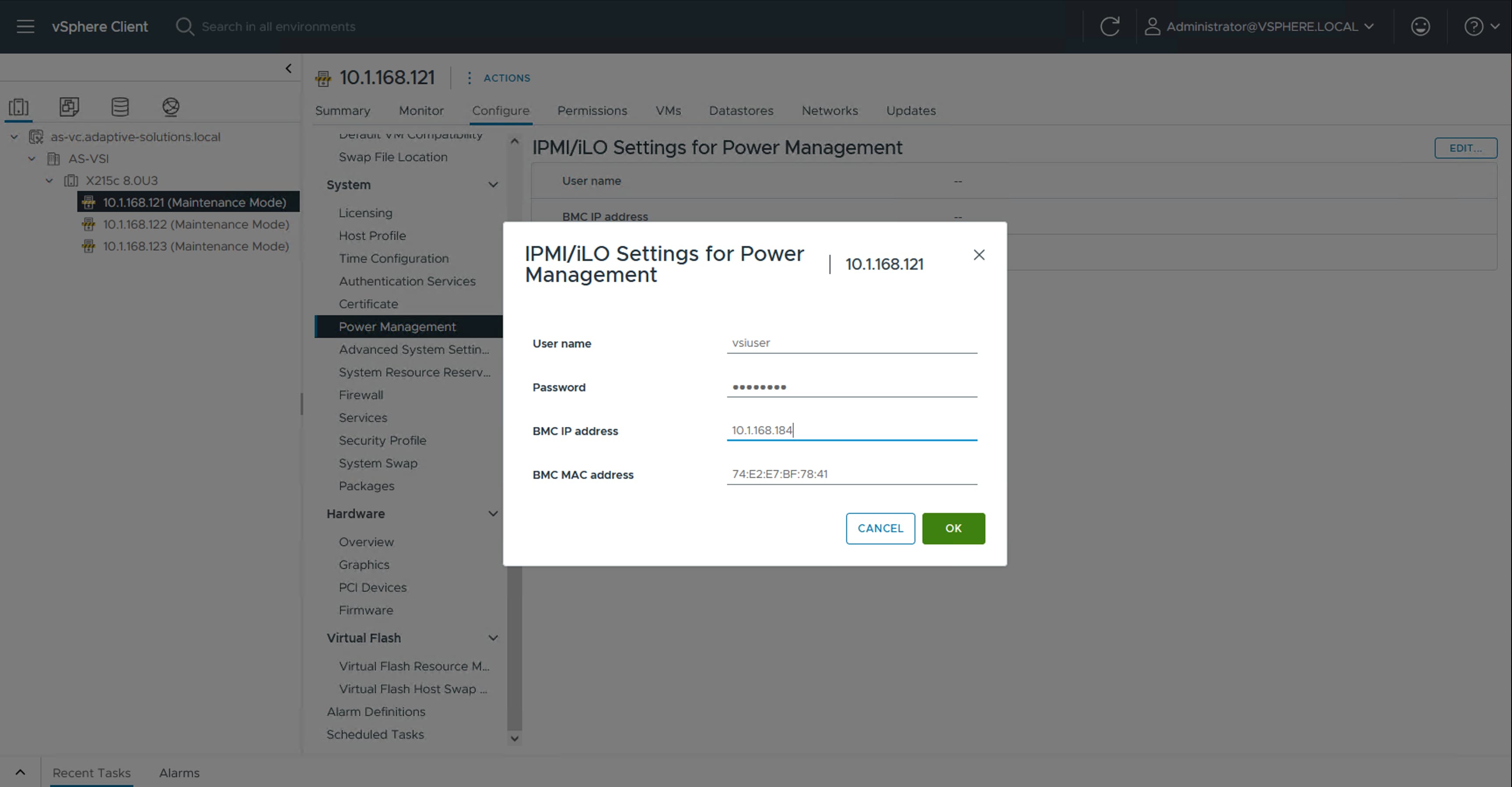
Step 7. Repeat Step 2 for each additional host in the cluster.
Note: The MAC addresses used in this configuration are associated with the physical hardware of the server and will need to be re-entered if the server profiles associated with these hosts are deployed to different servers.
Step 8. Go to Configure > Services > vSphere DRS for the cluster and click EDIT…. .
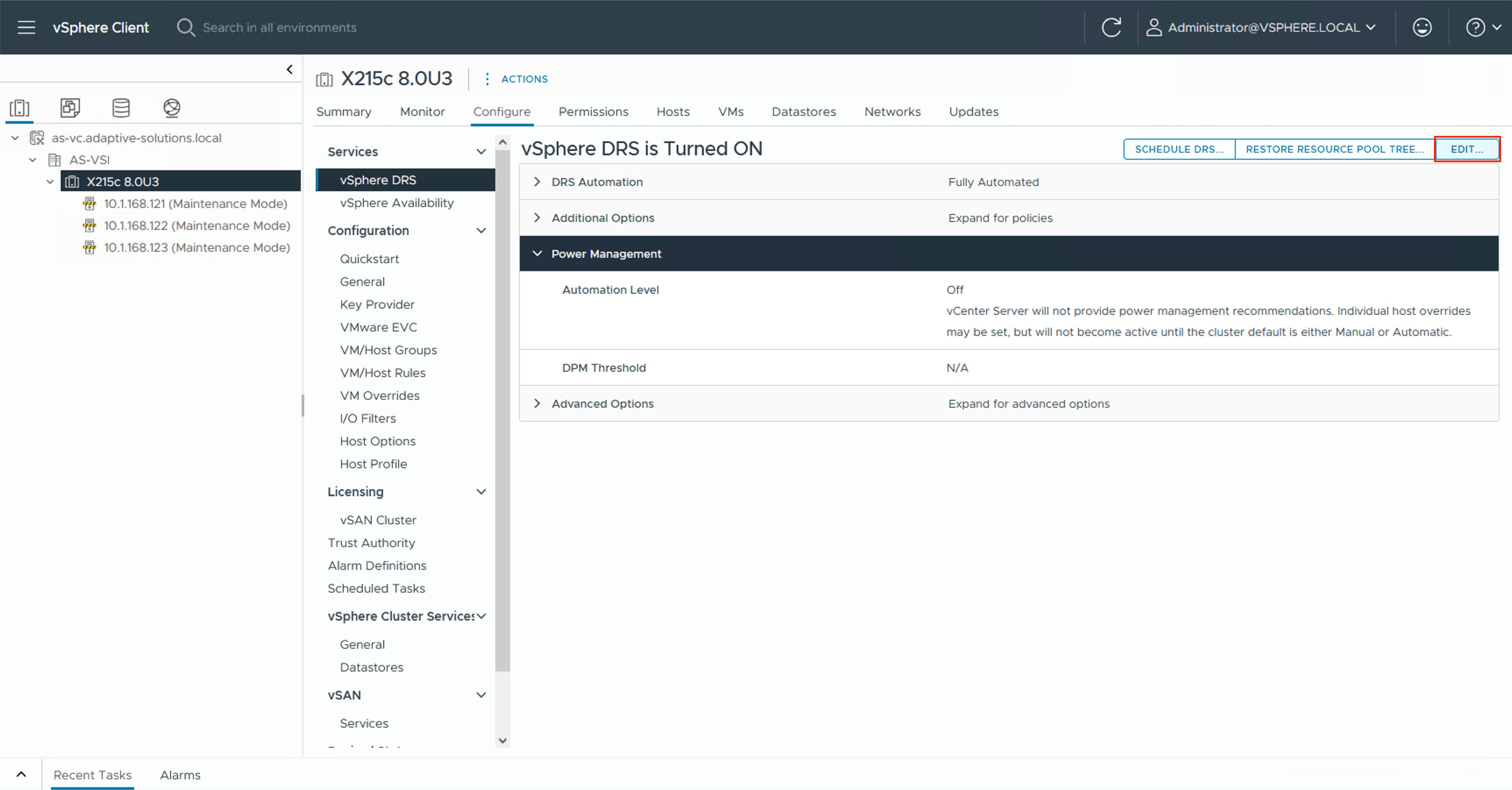
Step 9. Select the Power Management tab within the Edit Cluster Settings window, click the Enable checkbox for DPM, and select the Automatic option from the Automation Level drop-down list.
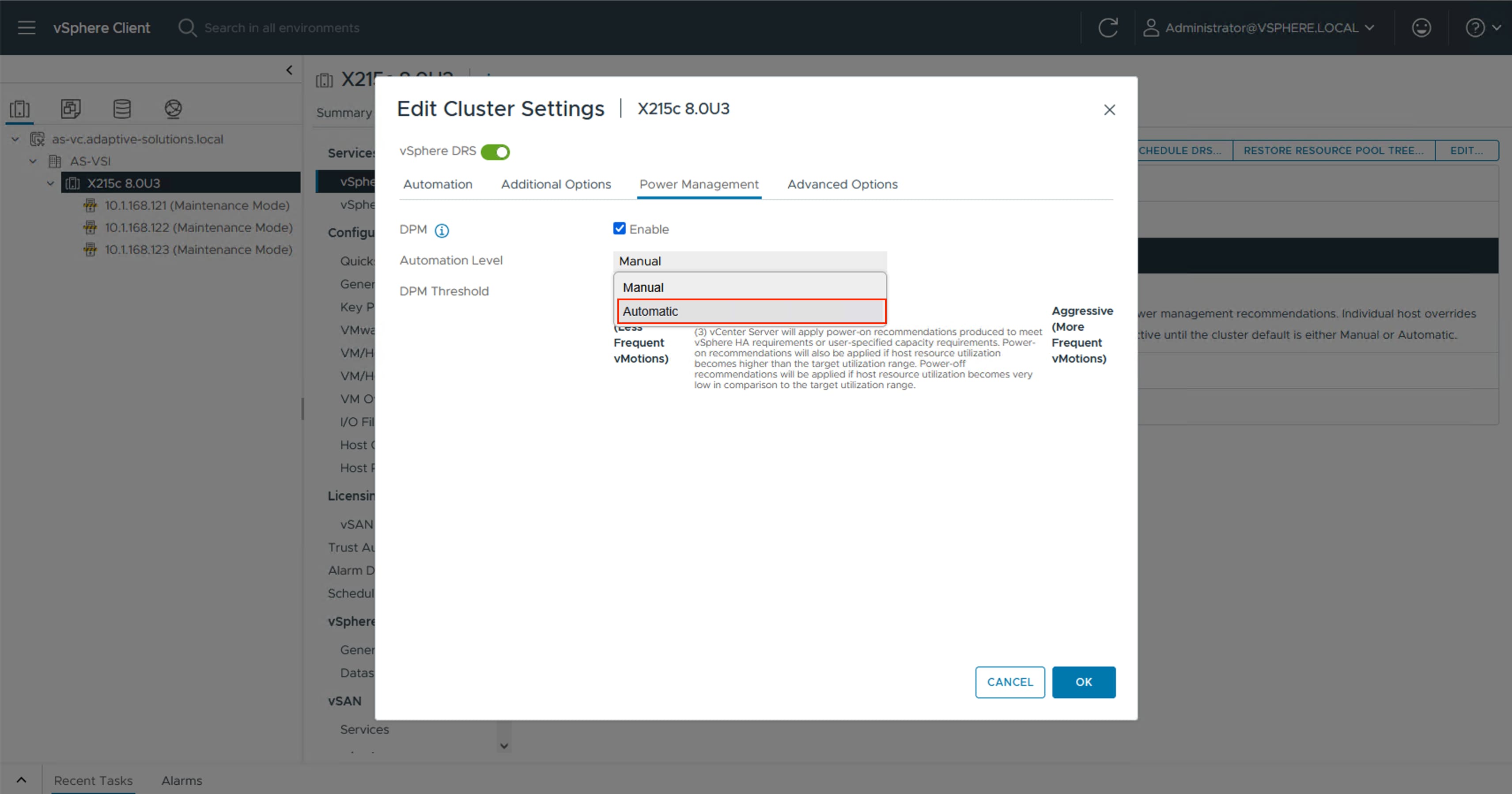
Step 10. Click OK to apply the changes.
Step 11. Click OK past any warnings about the standby functionality of certain hosts or alternately test each host for standby now that it has been configured and repeat Step 5.
Procedure 6. SQ Flow Control Setting
The VSP NVMe/TCP implementation does not implement SQ Flow Control, so for optimum performance, this should be disabled on each ESXi host. To disable the SQ Flow Control setting complete this procedure.
Step 1. Connect to each host via ssh and run the following commands:
[root@esxi-21:~] esxcli system module parameters list -m vmknvme |head -n 1;esxcli system module parameters list -m vmknvme | grep vmknvme_sq_flow_control_enabled
Name Type Value Description
vmknvme_sq_flow_control_enabled uint Enable/disable SQ flow control. Enabled: 1, disabled: 0, default: 1
[root@esxi-21:~] esxcli system module parameters set -m vmknvme -p " vmknvme_sq_flow_control_enabled=0"
[root@esxi-21:~] esxcli system module parameters list -m vmknvme |head -n 1;esxcli system module parameters list -m vmknvme | grep vmknvme_sq_flow_control_enabled
Name Type Value Description
vmknvme_sq_flow_control_enabled uint 0 Enable/disable SQ flow control. Enabled: 1, disabled: 0, default: 1
[root@esxi-21:~] reboot
This section provides the procedures to add and configure the VSP storage to hosts.
Procedure 1. Add NVMe over TCP Storage Adapter
The addition of the NVMe over TCP Storage Adapters requires the VSP subsystem NQN (NVMSS_NQN) for the namespace and the IP address of each controller. This information was previously configured in chapter Hitachi VSP One Block Storage Configuration, where the port IP assignment is detailed in Procedure 1, and the NVMSS_NQN is detailed in Procedure 3.
The example information is provided in Table 13.
Table 13. VSP One Block NVMe/TCP Storage Target Information
| Controller Port |
Controller IP |
NVMSS_NQN |
Port |
Host Storage Adapter |
| CL1-D |
10.0.41.5 |
nqn.1994-04.jp.co.hitachi:nvme:storage-subsystem-sn.8-10178-nvmssid.00010 |
4420 |
First NVMe over TCP Storage Adapter (vmhba64 in example) |
| CL2-D |
10.0.41.6 |
nqn.1994-04.jp.co.hitachi:nvme:storage-subsystem-sn.8-10178-nvmssid.00010 |
4420 |
First NVMe over TCP Storage Adapter (vmhba64 in example) |
| CL3-D |
10.0.42.5 |
nqn.1994-04.jp.co.hitachi:nvme:storage-subsystem-sn.8-10178-nvmssid.00010 |
4420 |
Second NVMe over TCP Storage Adapter (vmhba65 in example) |
| CL4-D |
10.0.42.6 |
nqn.1994-04.jp.co.hitachi:nvme:storage-subsystem-sn.8-10178-nvmssid.00010 |
4420 |
Second NVMe over TCP Storage Adapter (vmhba65 in example) |
Note: Perform these steps on each ESXi host.
Step 1. From the vSphere Client, click the Hosts and Clusters icon. Expand the datacenter and cluster to find the first ESXi host. Select the host and go to Configure > Storage > Storage Adapters.
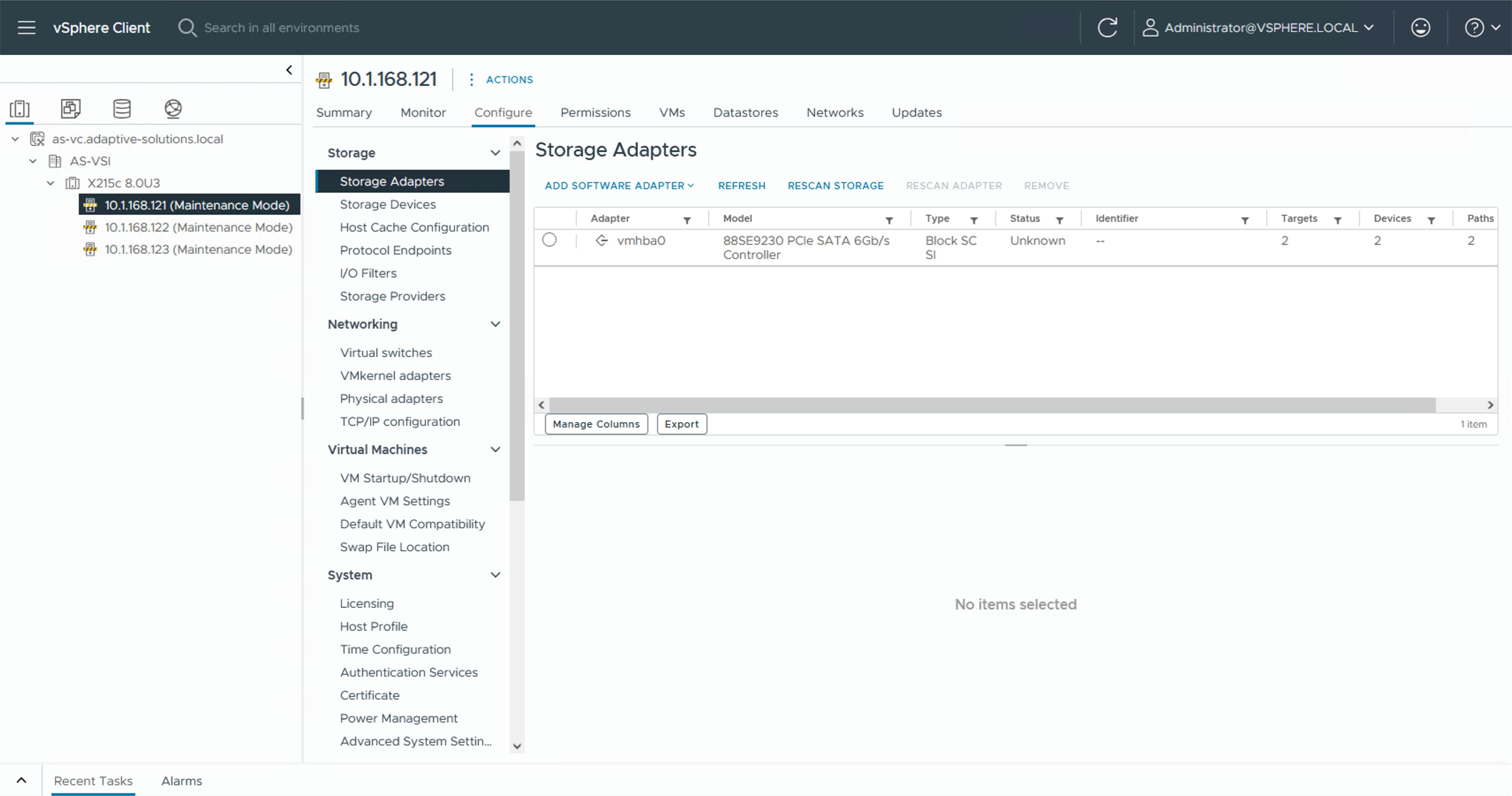
Step 2. Click ADD SOFTWARE ADAPTER and select Add NVMe over TCP adapter.
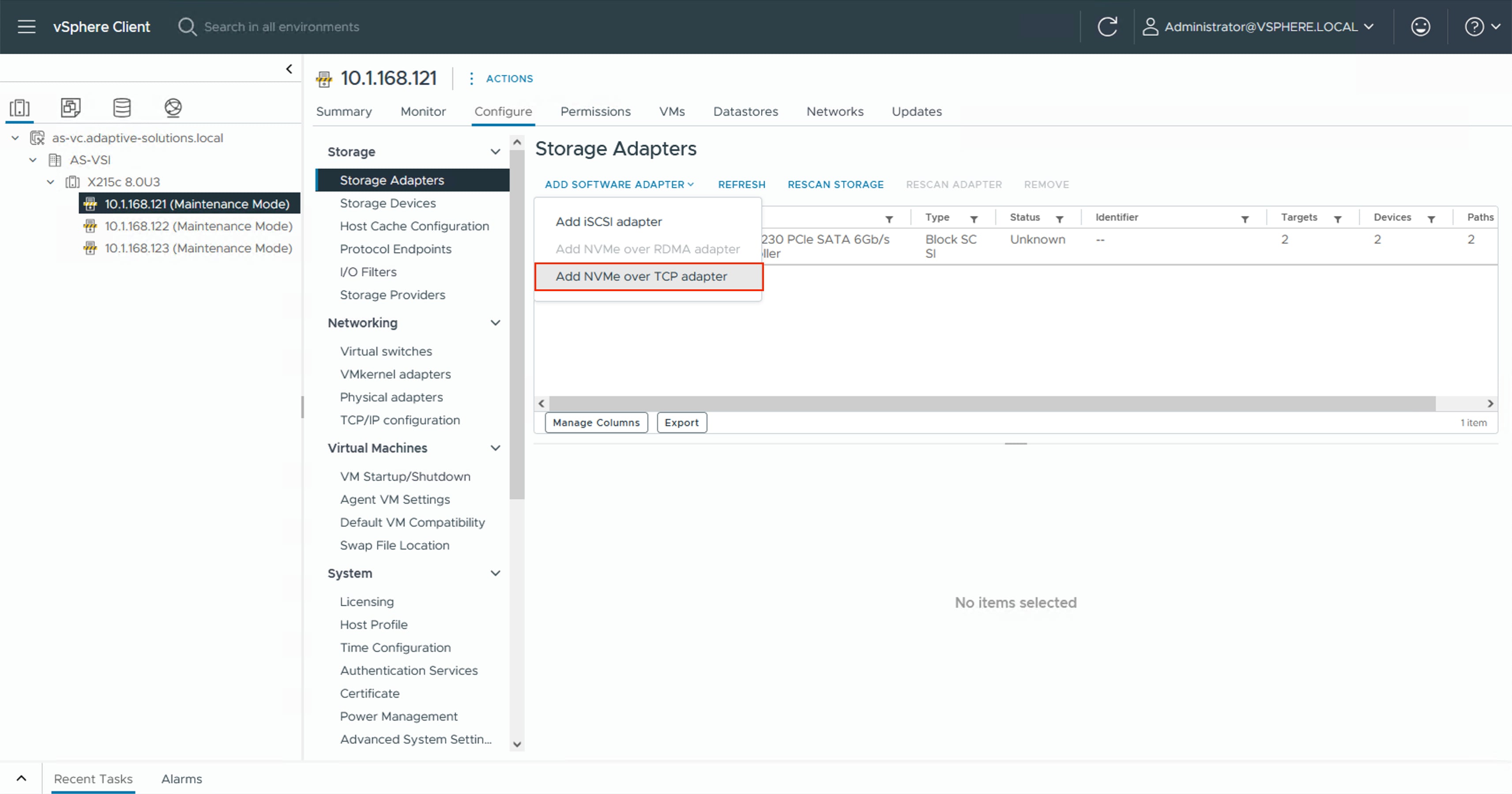
Step 3. Select the appropriate vmnic associated with IP Storage traffic. In this design, vmnic4.
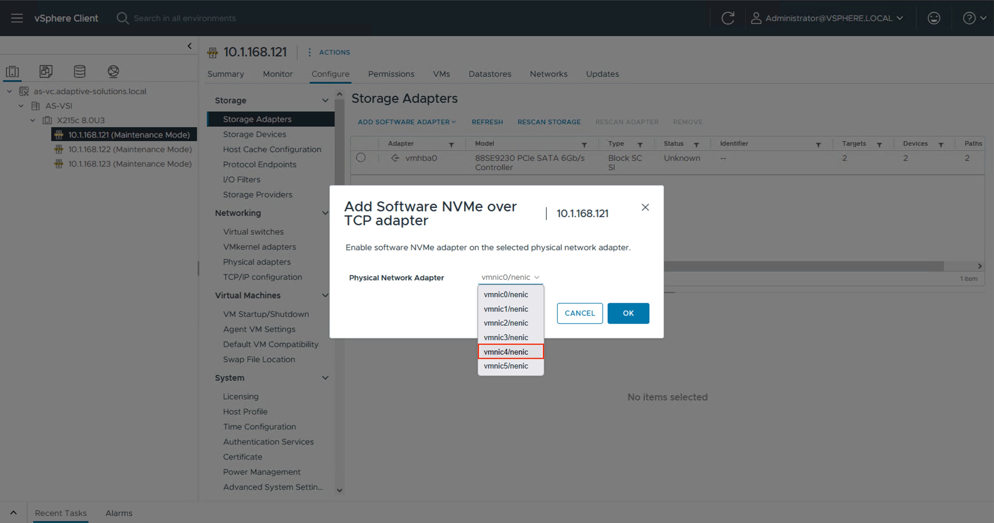
Step 4. Click OK.
Step 5. Repeat Steps 2-4 selecting the second vmnic associated with IP storage traffic. In this design, vmnic5.
Step 6. Click the first NVMe over TCP vmhba added, select Controllers and click ADD CONTROLLER.
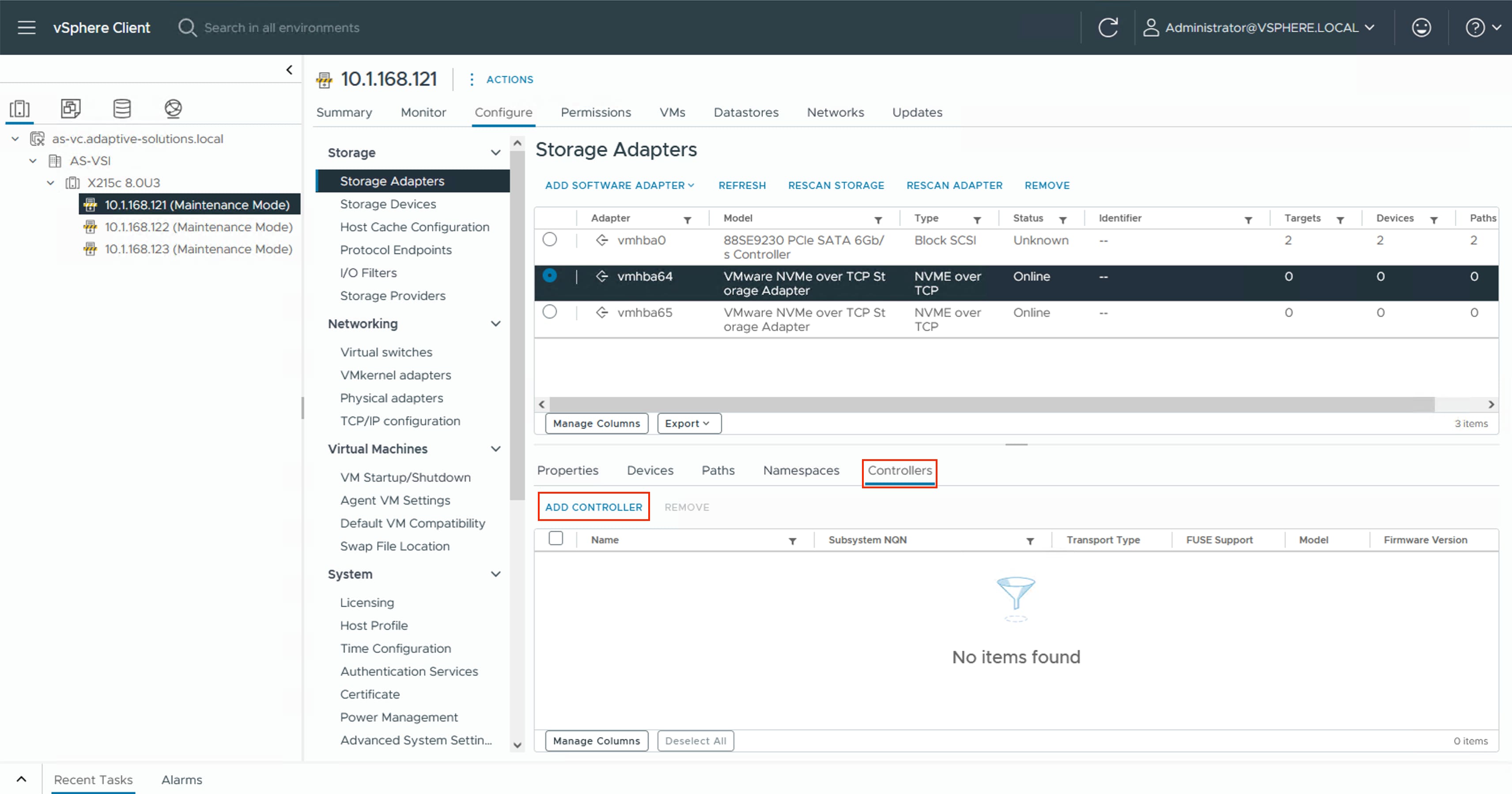
Step 7. Select to add the controller Manually. Specify the controller Subsystem NQN and IP address from Table 13 VSP One Block NVMe/TCP Storage Target Information, along with the Port Number 4420. Click OK.
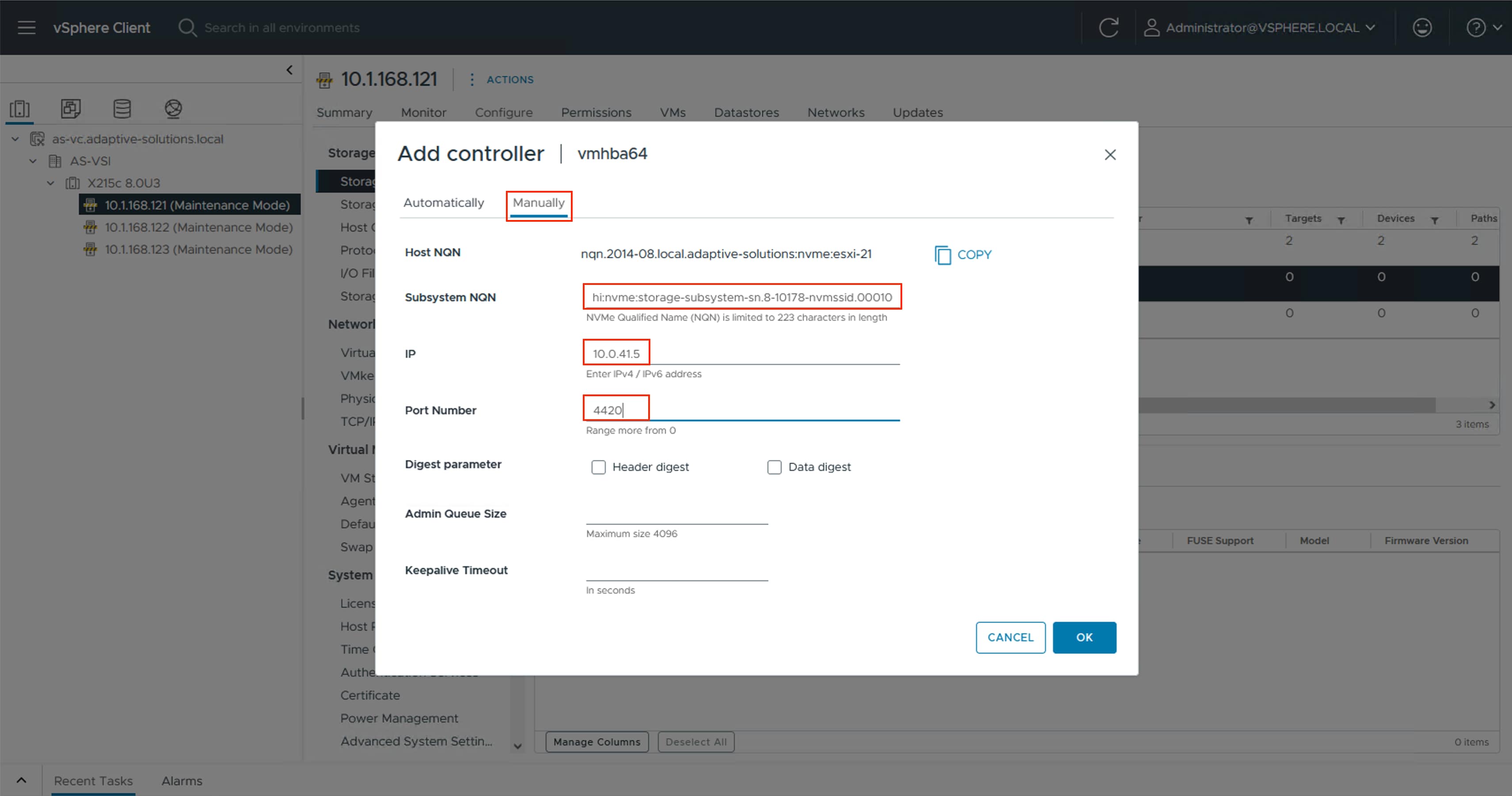
Step 8. Repeat Steps 6-7 for each additional controller. Ensure that you select the appropriate host storage adapter from Table 13.
Procedure 2. Add NVMe-TCP Datastores
With the storage adapters configured and the controllers added, you can add the provisioned NVMe/TCP datastores to the hosts.
Step 1. Select the first ESXi host. Right-click and select Storage > New Datastore…. .
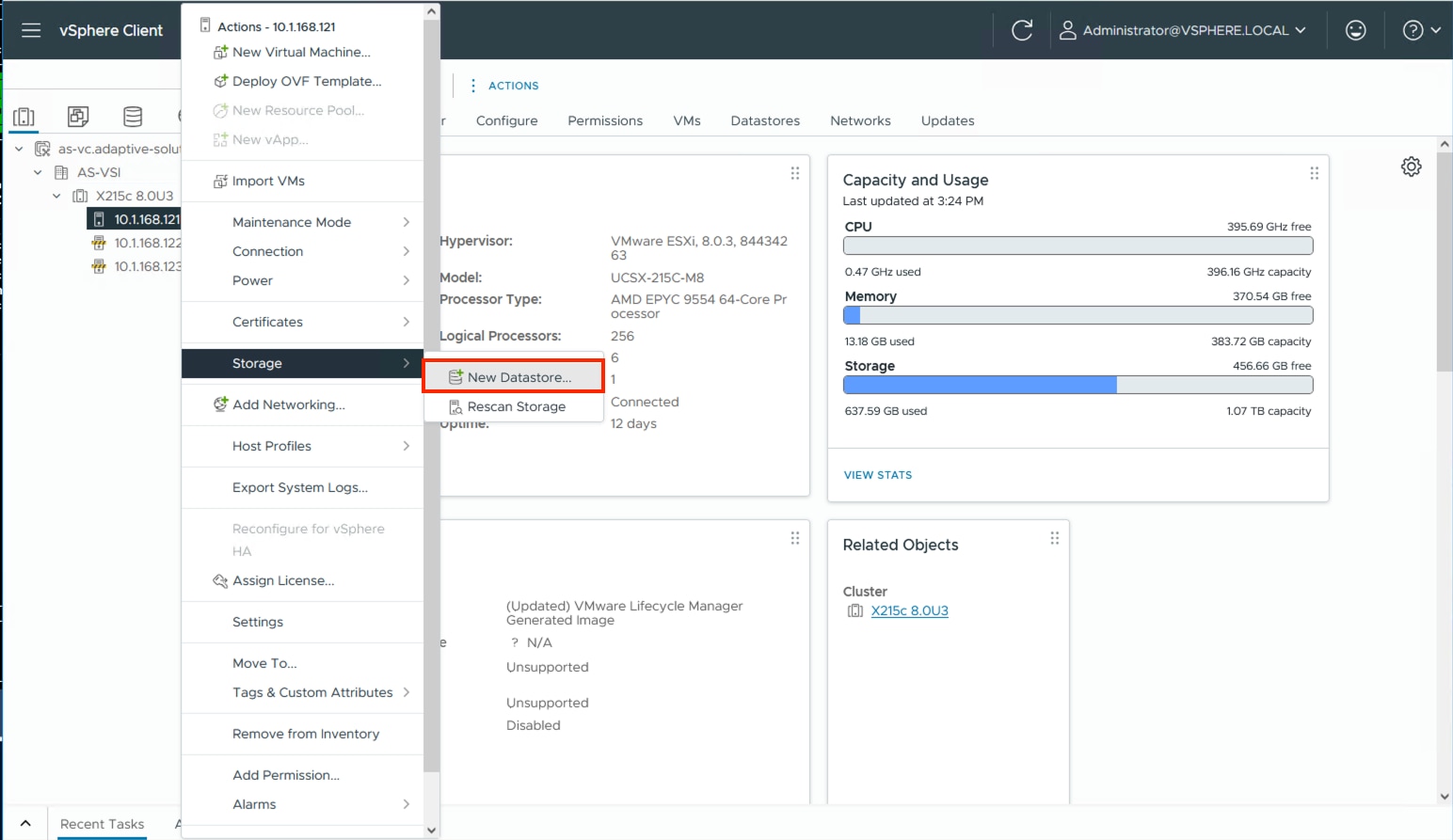
Step 2. In the New Datastore wizard, leave VMFS selected as the datastore name for the type and click NEXT.
Step 3. Select the allocated LUN, provide an appropriate name, and click NEXT.
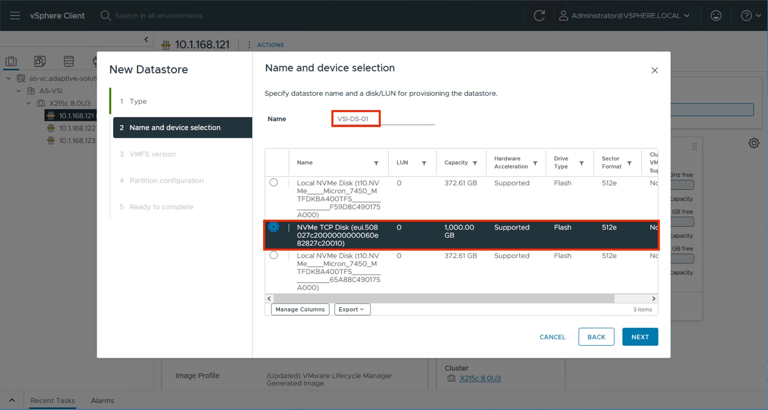
Step 4. Leave VMFS 6 selected and click NEXT.
Step 5. Leave the default options to use all available storage in the Partition configuration screen and click NEXT.
Step 6. Review the summary in the Ready to complete dialogue and click FINISH.
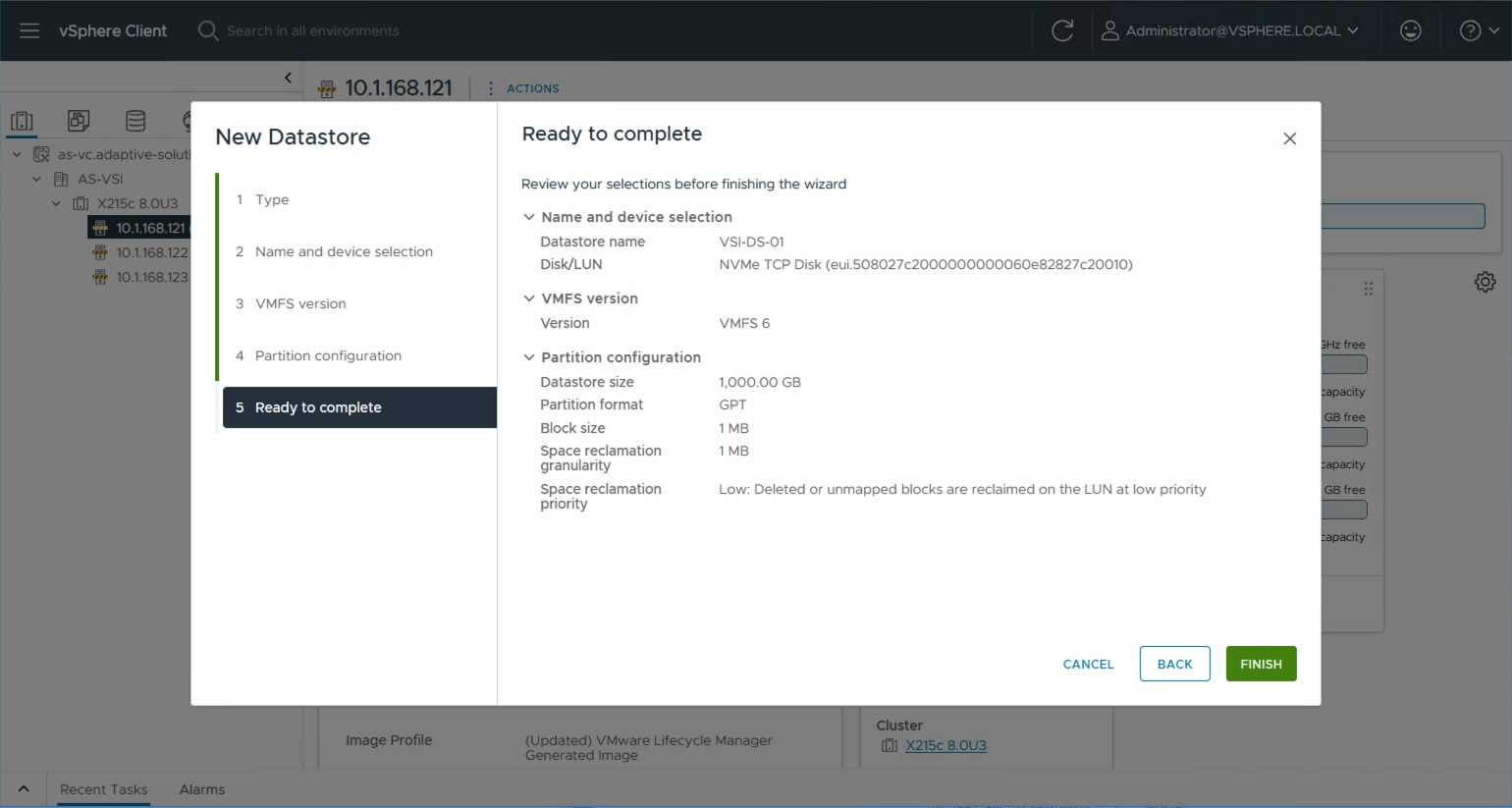
Step 7. Repeat Steps 1-6 for any additional datastores.
Step 8. For each additional host, right-click and select Rescan Storage.
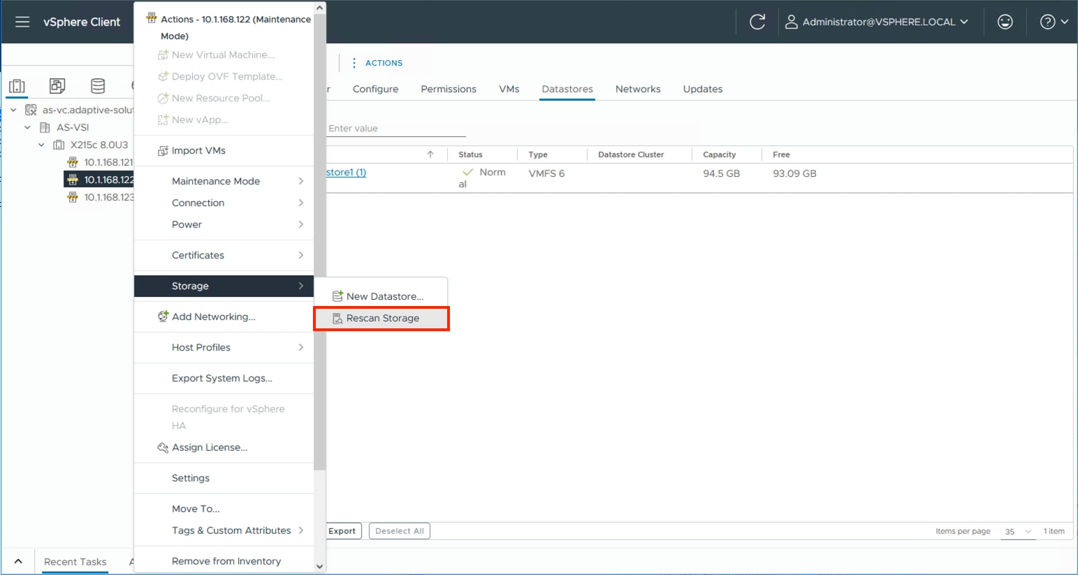
Step 9. Click OK in the list that appears.
About the Authors
Ramesh Isaac, Technical Marketing Engineer, Cisco Systems, Inc.
Ramesh Isaac is a Technical Marketing Engineer in the Cisco UCS Data Center Solutions Group. Ramesh has worked in the data center and mixed-use lab settings for over 25 years. He started in information technology supporting UNIX environments and focused on designing and implementing multi-tenant virtualization solutions in Cisco labs before entering Technical Marketing where he has supported converged infrastructure and virtual services as part of solution offerings as Cisco. Ramesh has held certifications from Cisco, VMware, and Red Hat.
Gilberto Pena Jr, Virtualization Solutions Architect, Hitachi Vantara
Gilberto Pena Jr. is a Virtualization Solutions Architect in the Engineering Converged UCP Group at Hitachi Vantara. He has over 25 years of experience working with enterprise financial customers, with a focus on LAN and WAN design, as well as converged and hyperconverged virtualization solutions. He has also held certifications from Cisco.
Acknowledgements
The authors would like to thank the following individuals for their support and contributions to the design, validation, and creation of this Cisco Validated Design:
● John George, Technical Marketing Engineer, Cisco Systems, Inc.
● Christopher Dudkiewicz, Engineering Product Manager, Cisco Systems, Inc.
● Arvin Jami, Product Owner - Solutions Architect, Hitachi Vantara
● Sreeram Vankadari, Product Management, Hitachi Vantara
Appendix
This appendix contains the following:
● Cisco Intersight Cloud Orchestrator using Hitachi VSP
● Ansible Automation of Solution Components
● Hitachi VSP Provisioning with VSP One Block Storage Modules for Red Hat Ansible
● Nexus Configurations used in this validation
Note: The features and functionality explained in this Appendix are optional configurations that can be helpful in configuring and managing the Adaptive Solutions deployment.
Cisco Intersight Cloud Orchestrator using Hitachi VSP
Intersight Cloud Orchestrator (ICO) enables administrators to configure and manage the Hitachi VSP. For a full list of capabilities and reference workflows, see the Virtual Storage Platform with Cisco Intersight Cloud Orchestrator Best Practices Guide.
For this validation, a custom ICO workflow to configure Hitachi VSP NVMe-oF resources and its subsequent deployment and execution steps can be found here: https://github.com/ucs-compute-solutions/Cisco_and_Hitachi_AdaptiveSolutions_IMM_X-Direct_VSP_One
Ansible Automation of Solution Components
Ansible by Red Hat is a popular open-source infrastructure and application automation tool that provides speed and consistency to deployments and configuration. Ansible is designed around these principles:
● Agent-less architecture - Low maintenance overhead by avoiding the installation of additional software across IT infrastructure.
● Simplicity - Automation playbooks use straightforward YAML syntax for code that reads like documentation. Ansible is decentralized, using SSH and existing OS credentials to access remote machines.
● Scalability and flexibility - Easily scale automated systems, through a modular design that supports a wide range of operating systems, cloud platforms, and network devices.
● Idempotence and predictability – If the system is already in the state described by a playbook, Ansible does not make changes, even if the playbook runs multiple times.
Ansible runs on many Linux platforms, Apple OSX, and MS Windows. Installation instructions vary between platforms. For this environment, the control host is a RHEL 8.10 VM, enabling Ansible-Core 2.16, which is required by Hitachi Vantara VSP One Block Storage Modules for Red Hat® Ansible® 3.5.0.
A base RHEL VM is installed as a control host with the following adjustments:
sudo dnf install ansible-core
sudo dnf config-manager --add-repo https://cli.github.com/packages/rpm/gh-cli.repo
sudo dnf install gh
ansible-galaxy collection install hitachivantara.vspone_block:==3.5.0
ansible-galaxy collection install cisco.intersight --force
Cisco UCS IMM Deployment with Ansible
The UCS IMM deployment will show the example setup of the UCS Domain Profile, and UCS Server Profiles configured through the creation of a Server Template.
The Intersight API key and Secrets.txt will need to be gathered using the information discussed here: https://community.cisco.com/t5/data-center-and-cloud-documents/intersight-api-overview/ta-p/3651994
Procedure 1. Gather Intersight API Key and Secrets.txt
Step 1. Log into Cisco Intersight and go to System > Settings > Keys.
Step 2. Click Generate API Key.
Step 3. Under Generate API Key, enter a Description, and select API key for OpenAPI schema version 3. Select a date for the Expiration Time and click Generate.
Step 4. Record the API Key ID, download the Secret Key and click Close.
Step 5. With the API Key ID and the Secret Key properly recorded, insert them into the group_vars folder in the GitHub repository: https://github.com/ucs-compute-solutions/Cisco_and_Hitachi_AdaptiveSolutions_IMM_X-Direct_VSP_One.
Step 6. Clone the repository to the intended Ansible control host in the working directory using the following command:
git clone https://github.com/ucs-compute-solutions/Cisco_and_Hitachi_AdaptiveSolutions_IMM_X-Direct_VSP_One
The cloned repository provides the following file and folder structure:
├── AdaptiveSolutions VSI X-Direct One Block Topology.png
├── group_vars
│ ├── all.yml
│ ├── secrets.sample
│ ├── secrets.yml
│ ├── ucs.yml
│ └── vsp_var.yml
├── ICO
│ └── Export_Workflow_Hitachi_VSP_NVMe-OF_Sequence.json
├── LICENSE
├── README.md
├── roles
│ ├── create_domain_profile
│ │ ├── defaults
│ │ │ └── main.yml
│ │ └── tasks
│ │ ├── build_domain_profile.yml
│ │ ├── main.yml
│ │ ├── setup_fi_a_port_policy.yml
│ │ ├── setup_fi_b_port_policy.yml
│ │ ├── setup_fi_vlan_policy.yml
│ │ ├── setup_link_control_udld_policy.yml
│ │ ├── setup_multicast_policy.yml
│ │ ├── setup_network_connectivity_policy.yml
│ │ ├── setup_ntp_policy.yml
│ │ └── setup_system_qos_policy.yml
│ ├── create_pools
│ │ ├── defaults
│ │ │ └── main.yml
│ │ └── tasks
│ │ ├── create_fc_ww_pools.yml
│ │ ├── create_ip_pools.yml
│ │ ├── create_mac_pools.yml
│ │ ├── create_uuid_pool.yml
│ │ └── main.yml
│ ├── create_server_policies
│ │ ├── defaults
│ │ │ └── main.yml
│ │ └── tasks
│ │ ├── create_bios_policies.yml
│ │ ├── create_boot_order_policy.yml
│ │ ├── create_chassis_power_policy.yml
│ │ ├── create_chassis_thermal_policy.yml
│ │ ├── create_ethernet_adapter_policies.yml
│ │ ├── create_ethernet_network_control_policy.yml
│ │ ├── create_ethernet_network_group_policy.yml
│ │ ├── create_ethernet_qos_policy.yml
│ │ ├── create_fc_adapter_policy.yml
│ │ ├── create_fc_lan_connectivity_policy.yml.orig
│ │ ├── create_fc_network_policy.yml
│ │ ├── create_fc_nvme_initiator_adapter_policy.yml
│ │ ├── create_fc_qos_policy.yml
│ │ ├── create_ipmi_policy.yml
│ │ ├── create_kvm_policy.yml
│ │ ├── create_san_connectivity_policy.yml
│ │ ├── create_vmedia_policy.yml
│ │ ├── gather_policy_info.yml
│ │ ├── gather_pool_info.yml
│ │ └── main.yml
│ └── create_server_profile_template
│ ├── defaults
│ │ └── main.yml
│ └── tasks
│ ├── gather_policy_info.yml
│ └── main.yml
├── Setup_IMM_Pools.yml
├── Setup_IMM_Server_Policies.yml
├── Setup_IMM_Server_Profile_Templates.yml
├── Setup_UCS_Domain_Profile.yml
└── VSP_NVMe_TCP_rev2.yml
Use of the repository is detailed within the base README of the repository. The secrets.sample file under the group_vars directory is an example of how the API Key ID and the Secret Key can be inserted in the secrets.yml file that will need to be created.
Adjustments will need to occur to the three group_vars files:
● all.yml – information relevant for referencing the base information of the configured UCS Domain.
● secrets.yml – the API Key ID and the Secret Key information referenced by all.yml
● ucs.yml – all information relevant to the intended Server Profiles created from the UCS Pools, Policies, and Server Profile Templates to be created.
Note: When adjusting the ucs.yml information, keep in mind the uniqueness requirement for the vNICs to avoid a conflict while creating the LAN Connectivity Policy.
Invocation is broken into three sections, separated by the following functions:
Step 7. Create the UCS Domain Profile (FI base configuration and port specification):
ansible-playbook ./Setup_UCS_Domain_Profile.yml
Step 8. Create the UCS Server Profile Pools (MAC,WWNN,WWPN,UUID,IP):
ansible-playbook . /Setup_IMM_Pools.yml
Step 9. Create the UCS Server Profile Policies:
ansible-playbook ./Setup_IMM_Server_Policies.yml
Step 10. Create the UCS Server Profile Template:
ansible-playbook ./Setup_IMM_Server_Profile_Templates.yml
Note: In each case, “--ask-vault-pass” should be added if the secrets.yml information has been encrypted with ansible-vault.
Hitachi VSP Provisioning with VSP One Block Storage Modules for Red Hat Ansible
Product user documentation and release notes for Storage Modules for Red Hat Ansible are available on the Hitachi Vantara Product Documentation website. These resources help identify the available storage modules that can be used to configure the Hitachi VSP One Block with NVMe/TCP.
For the most current documentation, including system requirements and important updates released after the product launch, see the Hitachi Vantara Product Documentation Portal.
The high-level deployment prerequisites include the following:
● Completion of the sections under Ansible Automation of Solution Components and Cisco UCS IMM Deployment with Ansible.
● VSP One Block has been configured and is accessible through VSP One Block Administrator.
● VSP One Block NVMe/TCP ports have been physically connected to the Cisco Nexus switches and have been logically configured.
● VSP_NVMe_TCP_rev2.yml – Ansible playbook for execution.
● ansible_vault_storage_var.yml - information relevant to the connectivity details for Hitachi VSP One Block.
1. To view the documentation for a storage module, enter the following command on the Ansible control node: “ansible-doc hitachivantara.vspone_block.vsp.<module_name>”
2. The “ansible_vault_storage_var.yml” will need to be edited within the group_vars directory of the cloned Github repository to reflect values appropriate for the environment. There is an example “ansible_vault_storage_var.sample” file that can be used as a reference.
3. Copy the “ansible_vault_storage_var.yml” from the group_vars directory of the cloned Github repository to $HOME/.ansible/collections/ansible_collections/hitachivantara/vspone_block/playbooks/ansible_vault_vars
The playbook “VSP_NVMe_TCP_rev2.yml” can be copied from the root directory of the cloned Github repository to $HOME/.ansible/collections/ansible_collections/hitachivantara/vspone_block/playbooks Playbook – VSP_NVMe_TCP_rev2.yml will:
● Create a DDP Pool.
● Create an LDEV.
● Create an NVMe subsystem.
● Assigning NVMe/TCP ports to the NVMe subsystem.
● Adding host NQNS to the NVMe subsystem.
● Assigning an NVMe Namespace ID to the LDEV.
● Assigning NVMe/TCP port paths to the NVMe Namespace ID of the LDEV.
The following are the supported modules in the sample playbook:
● Ansible Module “hv_ddp_pool” supports the following operations:
◦ Creating a DDP pool.
◦ Updating the DDP pool settings.
◦ Expanding the DDP pool size.
◦ Deleting the DDP pool size.
● Ansible Module “hv_ldev” supports the following operations:
◦ Creating an LDEV with a specific LDEV ID.
● Ansible Module “hv_nvm_subsystems” supports the operations:
◦ Creating an NVM Subsystem with a specific ID.
◦ Creating an NVM subsystem with a free ID.
◦ Adding host NQNs to an NVM subsystem with a specific ID.
◦ Adding host NQNs to an NVM subsystem with a specific Name.
◦ Adding namespaces and namespace paths to an NVM subsystem with a specific ID.
◦ Adding namespaces and namespace paths to an NVM subsystem with a specific Name.
◦ Adding ports to an NVM subsystem with a specific ID.
◦ Adding ports to an NVM subsystem with a specific name.
◦ Removing ports from an NVM subsystem with a specific name or ID.
◦ Removing namespace paths from an NVM subsystem with specific ID or name.
◦ Removing namespace from an NVM subsystem with specific ID or name using force.
◦ Removing host NQNs from an NVM subsystem with a specific ID or name.
◦ Removing host NQNs from an NVM subsystem with a specific ID or name using force.
◦ Updating host NQNs nickname of an NVM subsystem with a specific ID or name.
◦ Updating namespace nicknames of an NVM subsystem with a specific ID or name.
◦ Deleting an NVM subsystem with a specific ID.
◦ Deleting an NVM subsystem with a specific ID forcefully.
◦ Deleting an NVM subsystem with a specific name.
◦ Deleting an NVM subsystem with a specific name forcefully.
Procedure 1. Configure and deploy
Step 1. Log into the Ansible Control Host if you are not already connected.
Step 2. Update the copied ansible_vault_storage_var.yml file with the VSP One Block connection details.
Step 3. Update the copied custom GitHub playbook VSP_NVMe_TCP_rev2.yml task Create a DDP Pool with the required specifications, if you do not want to use the default values for your environment, see the following:
| Parameter |
Required |
Value/Description |
| pool_name |
No |
Name of the DDP Pool. |
| is_encryption_enabled |
No |
Whether encryption is enabled for the DDP Pool. Default: false. |
| threshold_warning |
Yes |
Warning threshold for the DDP Pool. |
| threshold_depletion |
Yes |
Depletion threshold for the DDP Pool. |
| drives |
No |
List of drives to be added to the DDP Pool. If not provided, all free drives will be used for DDP pool creation. |
| drive_type_code |
Yes |
Specify a drive type code consisting of 12 characters. Use the Get all disk drives playbook to obtain existing disk drive_type_code. |
| data_drive_count |
Yes |
Specify at least 9 for the number of data drives. If no count is provided, it will automatically be assigned with the recommended count. |
Step 4. Update the copied custom GitHub playbook VSP_NVMe_TCP_rev2.yml task Create LDEV with capacity saving and data_reduction_share with the following specifications as appropriate for your environment:
| Parameter |
Required |
Value/Description |
| state |
No |
Default: 'Present' |
| ldev_id |
Yes |
ID of the LDEV; for new LDEVs, it will be assigned if the ID is free. |
| pool_id |
Yes |
ID of the pool where the LUN will be created. |
| size |
Yes |
Size of the LDEV. Can be specified in units such as GB, TB, or MB (for example, '10GB', '5TB', '100MB'). |
| name |
No |
Name of the LDEV (optional). |
| capacity_saving |
Yes |
Whether capacity saving is (compression, compression_deduplication or disabled) - default is disabled |
| data_reduction_share |
Yes |
Specify whether to create a data reduction shared volume (Default=True for Thin Image advance direct connect). |
Step 5. Update the copied custom GitHub playbook VSP_NVMe_TCP_rev2.yml task Create an NVM Subsystem with a specific ID with the following specifications, adjusting them as appropriate for your environment:
| Parameter |
Required |
Value/Description |
| name |
No |
Name of the NVM subsystem. If not provided, a generated name will be smrha- . (smrha=Storage Module Red Hat Ansible) will be used. |
| id |
Yes |
ID of the NVM subsystem. Name or ID must be specified. |
| ports |
Yes |
Ports of the NVM subsystem. |
| host_mode |
Yes |
Host mode of the NVM subsystem (VMware_EX). |
| enable_namespace_security |
Yes |
Namespace security settings. |
| host_nqns |
Yes |
Host NQNs of the Cisco UCS hosts are associated with the subsystem. |
| namespaces |
Yes |
Namespaces of the NVM subsystem. |
| ldev_id |
Yes |
ldev_id |
| paths |
Yes |
Host NQNs are allowed to access the namespace. |
Sample Playbook – VSP_NVMe_TCP_rev2.yml:
---
################################################################################
# Example : NVMe/TCP Playbook - User must complete "Hitachi VSP One Block Storage for Red Hat Ansible" installation.
# - User must updated variables based on their requirements and environment.
################################################################################
- name: Logical Device Module
hosts: localhost
gather_facts: false
vars_files:
- "~/.ansible/collections/ansible_collections/hitachivantara/vspone_block/playbooks/ansible_vault_vars/ansible_vault_storage_var.yml"
vars:
# Common connection info for all tasks
connection_info:
address: "{{ storage_address }}"
username: "{{ vault_storage_username }}"
password: "{{ vault_storage_secret }}"
tasks:
############################################################################
# Task 1 : Create a DDP Pool
############################################################################
- name: Create a DDP Pool
hitachivantara.vspone_block.vsp.hv_ddp_pool:
connection_info: "{{ connection_info }}"
state: present
spec:
pool_name: "UCS_Application_Pool_1"
is_encryption_enabled: false
threshold_warning: 70
threshold_depletion: 80
drives:
- drive_type_code: "SNM5C-R3R8NC"
data_drive_count: 9
register: result
- name: Debug result
ansible.builtin.debug:
var: result
###########################################################################
# Task 2 : Create ldev with capacity saving and data_reduction_share
###########################################################################
- name: Create ldev with capacity saving and data_reduction_share
hitachivantara.vspone_block.vsp.hv_ldev:
connection_info: "{{ connection_info }}"
storage_system_info:
serial: "{{ storage_serial }}"
state: "present"
spec:
ldev_id: 250
pool_id: 1
size: "10GB"
capacity_saving: "compression_deduplication"
data_reduction_share: true
name: Application_VMFS_250
register: result
- name: Debug the result variable
ansible.builtin.debug:
var: result
############################################################################
# Task 3 : Create an NVM Subsystem with a specific ID
############################################################################
- name: Create an NVM Subsystem
hitachivantara.vspone_block.vsp.hv_nvm_subsystems:
connection_info: "{{ connection_info }}"
storage_system_info:
serial: "{{ storage_serial }}"
spec:
name: UCS_NVMe_TCP_VMware_Ansible_200
id: 200
ports: ["CL1-D", "CL2-D", "CL3-D", "CL4-D"]
host_mode: "VMWARE_EX"
enable_namespace_security: true
host_nqns:
- nqn: "nqn.2014-08.local.adaptive-solutions:nvme:esxi-21"
nickname: "host 21"
- nqn: "nqn.2014-08.local.adaptive-solutions:nvme:esxi-22"
nickname: "host 22"
- nqn: "nqn.2014-08.local.adaptive-solutions:nvme:esxi-23"
nickname: "host 23"
namespaces:
- ldev_id: 250
nickname: "LDEV250 Namespace"
paths:
- "nqn.2014-08.local.adaptive-solutions:nvme:esxi-21"
- "nqn.2014-08.local.adaptive-solutions:nvme:esxi-22"
- "nqn.2014-08.local.adaptive-solutions:nvme:esxi-23"
register: result
- name: Debug the result variable
ansible.builtin.debug:
var: result
Step 6. On the Ansible control node, run your playbook using the following command. This assumes the ansible_vault_storage_var.yml file has not been encrypted and is located in:
~/.ansible/collections/ansible_collections/hitachivantara/vspone_block/playbooks
[example_user@as-control vsp_direct]$ ansible-playbook VSP_NVMe_TCP_rev2.yml
Step 7. Upon successful execution of the playbook. Verify the creation of the NVMe subsystem using Raidcom commands or check the Hitachi VSP One Block system inventory within Cisco Intersight (IIS) to provisioned correctly.
Nexus Configurations used in this validation
Nexus A Configuration
version 10.4(5) Bios:version 05.53
switchname AA21-93600-1
vdc AA21-93600-1 id 1
limit-resource vlan minimum 16 maximum 4094
limit-resource vrf minimum 2 maximum 4096
limit-resource port-channel minimum 0 maximum 511
limit-resource m4route-mem minimum 58 maximum 58
limit-resource m6route-mem minimum 8 maximum 8
feature nxapi
feature bash-shell
cfs eth distribute
feature udld
feature interface-vlan
feature hsrp
feature lacp
feature vpc
feature lldp
clock summer-time EDT 2 Sunday March 02:00 1 Sunday November 02:00 60
feature telemetry
username admin password 5 $5$LPEEDD$I8n0a/ovGkzLCgIq.OQgVrhrRa5QY0xLAddG.nrCxR4 role network-admin
ip domain-lookup
ip domain-name adaptive-solutions.local
ip name-server 10.1.168.101
crypto key generate rsa label AA21-93600-1 modulus 1024
interface breakout module 1 port 27-28 map 10g-4x
interface breakout module 1 port 21,23 map 25g-4x
copp profile strict
snmp-server user admin network-admin auth md5 3746D2E94FC8C30BAA3BC4F3699B8E0055C6 priv aes-128 5236DEF2
02969C02A212A8AE7ED6934D5F8C localizedV2key
rmon event 1 log trap public description FATAL(1) owner PMON@FATAL
rmon event 2 log trap public description CRITICAL(2) owner PMON@CRITICAL
rmon event 3 log trap public description ERROR(3) owner PMON@ERROR
rmon event 4 log trap public description WARNING(4) owner PMON@WARNING
rmon event 5 log trap public description INFORMATION(5) owner PMON@INFO
ntp peer 10.1.168.14 use-vrf default
ntp server 10.81.254.202 use-vrf management
ntp peer 192.168.168.14 use-vrf default
ntp master 3
system default switchport
ip route 0.0.0.0/0 10.1.168.254
vlan 1-2,19,41-42,119,1000,1100-1102
vlan 2
name native-vlan
vlan 19
name OOB-mgmt
vlan 41
name nvme-tcp-a
vlan 42
name nvme-tcp-b
vlan 119
name ib-mgmt
vlan 1000
name vmotion
vlan 1100
name vm-traffic
vlan 1101
name vm-traffic-a
vlan 1102
name vm-traffic-b
spanning-tree port type edge bpduguard default
spanning-tree port type edge bpdufilter default
spanning-tree port type network default
vrf context management
ip route 0.0.0.0/0 192.168.168.254
port-channel load-balance src-dst l4port
vpc domain 10
peer-switch
role priority 10
peer-keepalive destination 192.168.168.14 source 192.168.168.13
delay restore 150
peer-gateway
auto-recovery
ip arp synchronize
interface Vlan1
no ip redirects
no ipv6 redirects
interface Vlan119
no shutdown
no ip redirects
ip address 10.1.168.13/24
no ipv6 redirects
interface Vlan1100
no shutdown
no ip redirects
ip address 10.1.100.252/24
no ipv6 redirects
hsrp 100
preempt
ip 10.1.100.254
interface Vlan1101
no shutdown
ip address 10.1.101.252/24
hsrp 101
preempt
priority 105
ip 10.1.101.254
interface Vlan1102
no shutdown
ip address 10.1.102.252/24
hsrp 102
preempt
ip 10.1.102.254
interface port-channel10
description vPC peer-link
switchport mode trunk
switchport trunk native vlan 2
switchport trunk allowed vlan 19,41-42,119,1000,1100-1102
spanning-tree port type network
speed 100000
duplex full
no negotiate auto
vpc peer-link
interface port-channel17
description AA24-9108-A
switchport mode trunk
switchport trunk native vlan 2
switchport trunk allowed vlan 31-32,41-42,119,1000,1100-1101
spanning-tree port type edge trunk
mtu 9216
vpc 17
interface port-channel18
description AA24-9108-B
switchport mode trunk
switchport trunk native vlan 2
switchport trunk allowed vlan 31-32,41-42,119,1000,1100,1102
spanning-tree port type edge trunk
mtu 9216
vpc 18
interface port-channel136
description MGMT-Uplink
switchport mode trunk
switchport trunk native vlan 2
switchport trunk allowed vlan 19,119
spanning-tree port type network
mtu 9216
vpc 136
interface Ethernet1/1
interface Ethernet1/2
interface Ethernet1/3
interface Ethernet1/4
interface Ethernet1/5
interface Ethernet1/6
interface Ethernet1/7
description AA24-9108-A:Eth1/7
switchport mode trunk
switchport trunk native vlan 2
switchport trunk allowed vlan 31-32,41-42,119,1000,1100-1101
mtu 9216
channel-group 17 mode active
no shutdown
interface Ethernet1/8
description AA24-9108-B:Eth1/7
switchport mode trunk
switchport trunk native vlan 2
switchport trunk allowed vlan 31-32,41-42,119,1000,1100,1102
mtu 9216
channel-group 18 mode active
no shutdown
interface Ethernet1/9
interface Ethernet1/10
interface Ethernet1/11
interface Ethernet1/12
interface Ethernet1/13
description AA23-VSP-One-CL1-D 100G
switchport access vlan 41
spanning-tree port type edge
mtu 9216
no shutdown
interface Ethernet1/14
description AA23-VSP-One-CL2-D 100G
switchport access vlan 41
spanning-tree port type edge
mtu 9216
no shutdown
interface Ethernet1/15
interface Ethernet1/16
interface Ethernet1/17
interface Ethernet1/18
interface Ethernet1/19
interface Ethernet1/20
interface Ethernet1/21
interface Ethernet1/22
interface Ethernet1/23
interface Ethernet1/24
interface Ethernet1/25
interface Ethernet1/26
interface Ethernet1/27/
interface Ethernet1/28
interface Ethernet1/29
description <nexus-b-hostname>:Eth1/29
switchport mode trunk
switchport trunk native vlan 2
switchport trunk allowed vlan 19,31-32,41-42,119,800,1000,1100-1102,1201-1202
speed 100000
duplex full
no negotiate auto
channel-group 10 mode active
no shutdown
interface Ethernet1/30
description <nexus-b-hostname>:Eth1/30
switchport mode trunk
switchport trunk native vlan 2
switchport trunk allowed vlan 19,31-32,41-42,119,800,1000,1100-1102,1201-1202
speed 100000
duplex full
no negotiate auto
channel-group 10 mode active
no shutdown
interface Ethernet1/31
interface Ethernet1/32
interface Ethernet1/33
interface Ethernet1/34
interface Ethernet1/35
interface Ethernet1/36
description <mgmt-uplink-switch-a-hostname>:<port>
switchport mode trunk
switchport trunk native vlan 2
switchport trunk allowed vlan 19,119
mtu 9216
channel-group 136 mode active
no shutdown
interface mgmt0
vrf member management
ip address 192.168.168.13/24
icam monitor scale
line console
line vty
boot nxos bootflash:/nxos64-cs.10.4.4.M.bin
Nexus B Configuration
version 10.4(5) Bios:version 05.53
switchname AA21-93600-2
vdc AA21-93600-2 id 1
limit-resource vlan minimum 16 maximum 4094
limit-resource vrf minimum 2 maximum 4096
limit-resource port-channel minimum 0 maximum 511
limit-resource m4route-mem minimum 58 maximum 58
limit-resource m6route-mem minimum 8 maximum 8
feature nxapi
feature bash-shell
cfs eth distribute
feature udld
feature interface-vlan
feature hsrp
feature lacp
feature vpc
feature lldp
clock summer-time EDT 2 Sunday March 02:00 1 Sunday November 02:00 60
feature telemetry
username admin password 5 $5$FFMNLD$jleNSaBR4dYYXNIU2WFfs.2BCl8tY3v/KsG.255JE5/ role network-admin
ip domain-lookup
ip domain-name adaptive-solutions.local
ip name-server 10.1.168.101
crypto key generate rsa label AA21-93600-2 modulus 2048
interface breakout module 1 port 21,23 map 25g-4x
copp profile strict
snmp-server user admin network-admin auth md5 3777EB3A39B7335F9884B2EB1D3FC5E6D259 priv aes-128 4962845B
19D763649384E2E05F5CDCA4DB3A localizedV2key
rmon event 1 log trap public description FATAL(1) owner PMON@FATAL
rmon event 2 log trap public description CRITICAL(2) owner PMON@CRITICAL
rmon event 3 log trap public description ERROR(3) owner PMON@ERROR
rmon event 4 log trap public description WARNING(4) owner PMON@WARNING
rmon event 5 log trap public description INFORMATION(5) owner PMON@INFO
ntp peer 10.1.168.13 use-vrf default
ntp server 10.81.254.202 use-vrf management
ntp peer 192.168.168.13 use-vrf default
ntp master 3
system default switchport
ip route 0.0.0.0/0 10.1.168.254
ip route 0.0.0.0/0 192.168.168.254
vlan 1-2,19,41-42,119,1000,1100-1102
vlan 2
name native-vlan
vlan 19
name OOB-mgmt
vlan 41
name nvme-tcp-a
vlan 42
name nvme-tcp-b
vlan 119
name ib-mgmt
vlan 1000
name vmotion
vlan 1100
name vm-traffic
vlan 1101
name vm-traffic-a
vlan 1102
name vm-traffic-b
spanning-tree port type edge bpduguard default
spanning-tree port type edge bpdufilter default
spanning-tree port type network default
vrf context management
ip route 0.0.0.0/0 192.168.168.254
port-channel load-balance src-dst l4port
vpc domain 10
peer-switch
role priority 20
peer-keepalive destination 192.168.168.13 source 192.168.168.14
delay restore 150
peer-gateway
auto-recovery
ip arp synchronize
interface Vlan1
no ip redirects
no ipv6 redirects
interface Vlan119
no shutdown
no ip redirects
ip address 10.1.168.14/24
no ipv6 redirects
interface Vlan1100
no shutdown
no ip redirects
ip address 10.1.100.253/24
no ipv6 redirects
hsrp 100
preempt
priority 105
ip 10.1.100.254
interface Vlan1101
no shutdown
ip address 10.1.101.253/24
hsrp 101
preempt
ip 10.1.101.254
interface Vlan1102
no shutdown
ip address 10.1.102.253/24
hsrp 102
preempt
priority 105
ip 10.1.102.254
interface port-channel10
description vPC peer-link
switchport mode trunk
switchport trunk native vlan 2
switchport trunk allowed vlan 19,31-32,41-42,119,800,1000,1100-1102,1201-1202
spanning-tree port type network
speed 100000
duplex full
no negotiate auto
vpc peer-link
interface port-channel17
description AA24-9108-A
switchport mode trunk
switchport trunk native vlan 2
switchport trunk allowed vlan 31-32,41-42,119,1000,1100-1101
spanning-tree port type edge trunk
mtu 9216
vpc 17
interface port-channel18
description AA24-9108-B
switchport mode trunk
switchport trunk native vlan 2
switchport trunk allowed vlan 31-32,41-42,119,1000,1100,1102
spanning-tree port type edge trunk
mtu 9216
vpc 18
interface port-channel136
description MGMT-Uplink
switchport mode trunk
switchport trunk native vlan 2
switchport trunk allowed vlan 19,119
spanning-tree port type network
mtu 9216
vpc 136
interface Ethernet1/1
interface Ethernet1/2
interface Ethernet1/3
interface Ethernet1/4
interface Ethernet1/5
interface Ethernet1/6
interface Ethernet1/7
description AA24-9108-A:Eth1/8
switchport mode trunk
switchport trunk native vlan 2
switchport trunk allowed vlan 31-32,41-42,119,1000,1100-1101
mtu 9216
channel-group 17 mode active
no shutdown
interface Ethernet1/8
description AA24-9108-B:Eth1/8
switchport mode trunk
switchport trunk native vlan 2
switchport trunk allowed vlan 31-32,41-42,119,1000,1100,1102
mtu 9216
channel-group 18 mode active
no shutdown
interface Ethernet1/9
interface Ethernet1/10
interface Ethernet1/11
interface Ethernet1/12
interface Ethernet1/13
description AA23-VSP-One-CL3-D 100G
switchport access vlan 42
spanning-tree port type edge
mtu 9216
no shutdown
interface Ethernet1/14
description AA23-VSP-One-CTL4-D 100G
switchport access vlan 42
spanning-tree port type edge
mtu 9216
no shutdown
interface Ethernet1/15
interface Ethernet1/16
interface Ethernet1/17
interface Ethernet1/18
interface Ethernet1/19
interface Ethernet1/20
interface Ethernet1/21
interface Ethernet1/22
interface Ethernet1/23
interface Ethernet1/24
interface Ethernet1/25
interface Ethernet1/26
interface Ethernet1/27
interface Ethernet1/28
interface Ethernet1/29
description <nexus-a-hostname>:Eth1/29
switchport mode trunk
switchport trunk native vlan 2
switchport trunk allowed vlan 19,31-32,41-42,119,800,1000,1100-1102,1201-1202
speed 100000
duplex full
no negotiate auto
channel-group 10 mode active
no shutdown
interface Ethernet1/30
description <nexus-a-hostname>:Eth1/30
switchport mode trunk
switchport trunk native vlan 2
switchport trunk allowed vlan 19,31-32,41-42,119,800,1000,1100-1102,1201-1202
speed 100000
duplex full
no negotiate auto
channel-group 10 mode active
no shutdown
interface Ethernet1/31
interface Ethernet1/32
interface Ethernet1/33
interface Ethernet1/34
interface Ethernet1/35
interface Ethernet1/36
description <mgmt-uplink-switch-a-hostname>:<port>
switchport mode trunk
switchport trunk native vlan 2
switchport trunk allowed vlan 19,119
mtu 9216
channel-group 136 mode active
no shutdown
interface mgmt0
vrf member management
ip address 192.168.168.14/24
icam monitor scale
line console
line vty
boot nxos bootflash:/nxos64-cs.10.4.4.M.bin
Table 14. Cisco UCS and Nexus Components
| Part Number |
Description |
Service Duration (Months) |
Qty |
| UCSX-M8-MLB |
UCSX M8 Modular Server and Chassis MLB |
--- |
1 |
| DC-MGT-SAAS |
Cisco Intersight SaaS |
--- |
1 |
| SAAS-OTHER |
Other Use Case |
--- |
1 |
| DC-MGT-IS-SAAS-AD |
Infrastructure Services SaaS/CVA - Advantage |
--- |
3 |
| SVS-DCM-SUPT-BAS |
Cisco Support Standard for DCM |
--- |
1 |
| DC-MGT-UCSC-1S |
UCS Central Per Server - 1 Server License |
--- |
3 |
| DC-MGT-ADOPT-BAS |
Intersight - Virtual adopt session http://cs.co/requestCSS |
--- |
1 |
| UCSX-9508-D-U |
UCS 9508 Chassis Configured |
--- |
1 |
| CON-L1NCO-UCSX9958 |
CX LEVEL 1 8X7XNCDOS UCS 9508 Chassis Configured |
36 |
1 |
| UCSX-215C-M8 |
UCS X215c M8 Compute Node 2S w/o CPU, Memory, storage, Mezz |
--- |
3 |
| CON-L1NCO-UCSX2CMA |
CX LEVEL 1 8X7XNCDOS UCS X215c M8 Compute Node 2S w o CPU, M |
36 |
3 |
| UCSX-CHASSIS-SW-D |
Platform SW (Recommended) latest release for X9500 Chassis |
--- |
1 |
| UCSX-9508-CAK-D |
UCS 9508 Chassis Accessory Kit |
--- |
1 |
| UCSX-9508-RBLK-D |
UCS 9508 Chassis Active Cooling Module (FEM slot) |
--- |
2 |
| UCSX-9508-ACPEM-D |
UCS 9508 Chassis Rear AC Power Expansion Module |
--- |
2 |
| UCSX-9508-KEYAC-D |
UCS 9508 AC PSU Keying Bracket |
--- |
1 |
| UCSX-9508-FSBK-D |
UCS 9508 Chassis Front Node Slot Blank |
--- |
5 |
| IMM-MANAGED |
Deployment mode for UCS FI connected Servers in IMM mode |
--- |
3 |
| UCSX-CPU-A9135 |
AMD 9135 3.65GHz 200W 16C/64MB Cache DDR5 6000MT/s |
--- |
6 |
| UCSX-V4-PCIME-D |
UCS PCI Mezz card for X-Fabric |
--- |
3 |
| UCSX-MLV5D200GV2D |
Cisco VIC 15230 2x 100G mLOM X-Series w/Secure Boot |
--- |
3 |
| UCSX-M2-240G-D |
240GB M.2 SATA Micron G2 SSD |
--- |
6 |
| UCSX-M2-HWRD-FPS |
UCSX Front panel with M.2 RAID controller for SATA drives |
--- |
3 |
| UCSX-C-SW-LATEST-D |
Platform SW (Recommended) latest release X-Series ComputeNode |
--- |
3 |
| UCSX-TPM2-002D-D |
TPM 2.0 FIPS 140-2 MSW2022 compliant AMD M8 servers |
--- |
3 |
| UCS-DDR5-BLK |
UCS DDR5 DIMM Blanks |
--- |
48 |
| UCSX-M8A-HS-F |
Front Heatsink for AMD X series servers |
--- |
3 |
| UCSX-M8A-HS-R |
Rear Heatsink for AMD X series servers |
--- |
3 |
| UCSX-M8A-FMEZZBLK |
Front Mezzanine Blank M8 X series servers |
--- |
3 |
| UCSX-MR128G2RG5 |
128GB DDR5-6400 RDIMM 2Rx4 (32Gb) |
--- |
24 |
| UCSX-S9108-100G |
UCS X-Series Direct Fabric Interconnect 9108 100G |
--- |
2 |
| UCSX-S9108-SW |
Perpetual SW License for UCS X-Series Direct FI 9108-100G |
--- |
2 |
| UCSX-PSU-2800AC-D |
UCS 9508 Chassis 2800V AC Dual Voltage PSU Titanium |
--- |
6 |
| CAB-C19-CBN |
Cabinet Jumper Power Cord, 250 VAC 16A, C20-C19 Connectors |
--- |
6 |
| N9K-C93600CD-GX |
Nexus 9300 Series, 28p 100G and 8p 400G Switch |
--- |
2 |
| CON-L1NCD-N9KC936G |
CX LEVEL 1 8X7NCD Nexus 9300 with 28p 100G and 8p 400G |
36 |
2 |
| NXK-AF-PI |
Dummy PID for Airflow Selection Port-side Intake |
--- |
2 |
| MODE-NXOS |
Mode selection between ACI and NXOS |
--- |
2 |
| NXOS-CS-10.4.5M |
Nexus 9300, 9500, 9800 NX-OS SW 10.4.5 (64bit) Cisco Silicon |
--- |
2 |
| NXK-ACC-KIT-1RU |
Nexus 3K/9K Fixed Accessory Kit, 1RU front and rear removal |
--- |
2 |
| NXA-FAN-35CFM-PI |
Nexus Fan, 35CFM, port side intake airflow |
--- |
12 |
| NXA-PAC-1100W-PI2 |
Nexus AC 1100W PSU - Port Side Intake |
--- |
4 |
| CAB-C13-C14-AC |
Power cord, C13 to C14 (recessed receptacle), 10A |
--- |
4 |
| NXOS-SLP-INFO-9K |
Info PID for Smart Licensing using Policy for N9K |
--- |
2 |
| DCN-OTHER |
Select if this product will NOT be used for AI Applications |
--- |
2 |
| QSFP-100G-AOC5M |
100GBASE QSFP Active Optical Cable, 5m |
--- |
2 |
| QSFP-100G-SR1.2 |
100G SR1.2 BiDi QSFP Transceiver, LC, 100m OM4 MMF |
--- |
4 |
| C1A1TN9300XF2-3Y |
Data Center Networking Advantage Term N9300 XF2, 3Y |
--- |
2 |
| SVS-L1N9KA-XF2-3Y |
Cisco Support Enhanced for DCN Advantage Term N9300 XF2, 3Y |
--- |
2 |
| SW-OTHER |
Select if this product will NOT be used for AI Applications |
--- |
2 |
Table 15. Hitachi VSP One Block
| Part Number |
Description |
Service Duration (Months) |
Qty |
| VSP-B24-A0001.S |
VSP One Block 24 Appliance Product |
36 |
1 |
| VSP-B24-CP-BSW-ECFM.P |
VSP One B24 Node (VSP-B24-CP-BSW-ECFM.P) |
36 |
1 |
| VSP-B24-SSD-NG4-3R8TB.P |
VSP One Block 24 NVMe SSD G4 3.8TB (VSP-B24-SSD-NG4-3R8TB.P) |
-- |
24 |
| VSP-B28-A0001.S |
VSP One Block 28 Appliance Product |
-- |
1 |
| VSP-B20-BE-NVME.P |
VSP One B20 NVMe Board2 Pair (VSP-B20-BE-NVME.P) |
-- |
2 |
| VSP-B20-BE-100GOPT.P |
VSP One B20 IO Module Eth 100G with SFP (VSP-B20-BE-100GOpt.P) |
-- |
4 |
Feedback
For comments and suggestions about this guide and related guides, join the discussion on Cisco Community here: https://cs.co/en-cvds.
CVD Program
ALL DESIGNS, SPECIFICATIONS, STATEMENTS, INFORMATION, AND RECOMMENDATIONS (COLLECTIVELY, "DESIGNS") IN THIS MANUAL ARE PRESENTED "AS IS," WITH ALL FAULTS. CISCO AND ITS SUPPLIERS DISCLAIM ALL WARRANTIES, INCLUDING, WITHOUT LIMITATION, THE WARRANTY OF MERCHANTABILITY, FITNESS FOR A PARTICULAR PURPOSE AND NONINFRINGEMENT OR ARISING FROM A COURSE OF DEALING, USAGE, OR TRADE PRACTICE. IN NO EVENT SHALL CISCO OR ITS SUPPLIERS BE LIABLE FOR ANY INDIRECT, SPECIAL, CONSEQUENTIAL, OR INCIDENTAL DAMAGES, INCLUDING, WITHOUT LIMITATION, LOST PROFITS OR LOSS OR DAMAGE TO DATA ARISING OUT OF THE USE OR INABILITY TO USE THE DESIGNS, EVEN IF CISCO OR ITS SUPPLIERS HAVE BEEN ADVISED OF THE POSSIBILITY OF SUCH DAMAGES.
THE DESIGNS ARE SUBJECT TO CHANGE WITHOUT NOTICE. USERS ARE SOLELY RESPONSIBLE FOR THEIR APPLICATION OF THE DESIGNS. THE DESIGNS DO NOT CONSTITUTE THE TECHNICAL OR OTHER PROFESSIONAL ADVICE OF CISCO, ITS SUPPLIERS OR PARTNERS. USERS SHOULD CONSULT THEIR OWN TECHNICAL ADVISORS BEFORE IMPLE-MENTING THE DESIGNS. RESULTS MAY VARY DEPENDING ON FACTORS NOT TESTED BY CISCO.
CCDE, CCENT, Cisco Eos, Cisco Lumin, Cisco Nexus, Cisco StadiumVision, Cisco TelePresence, Cisco WebEx, the Cisco logo, DCE, and Welcome to the Human Network are trademarks; Changing the Way We Work, Live, Play, and Learn and Cisco Store are service marks; and Access Registrar, Aironet, AsyncOS, Bringing the Meeting To You, Catalyst, CCDA, CCDP, CCIE, CCIP, CCNA, CCNP, CCSP, CCVP, Cisco, the Cisco Certified Internetwork Expert logo, Cisco IOS, Cisco Press, Cisco Systems, Cisco Systems Capital, the Cisco Systems logo, Cisco Unified Computing System (Cisco UCS), Cisco UCS B-Series Blade Servers, Cisco UCS C-Series Rack Servers, Cisco UCS S-Series Storage Servers, Cisco UCS X-Series, Cisco UCS Manager, Cisco UCS Management Software, Cisco Unified Fabric, Cisco Application Centric Infrastructure, Cisco Nexus 9000 Series, Cisco Nexus 7000 Series. Cisco Prime Data Center Network Manager, Cisco NX-OS Software, Cisco MDS Series, Cisco Unity, Collaboration Without Limitation, EtherFast, EtherSwitch, Event Center, Fast Step, Follow Me Browsing, FormShare, GigaDrive, HomeLink, Internet Quotient, IOS, iPhone, iQuick Study, LightStream, Linksys, MediaTone, MeetingPlace, MeetingPlace Chime Sound, MGX, Networkers, Networking Academy, Network Registrar, PCNow, PIX, PowerPanels, ProConnect, ScriptShare, SenderBase, SMARTnet, Spectrum Expert, StackWise, The Fastest Way to Increase Your Internet Quotient, TransPath, WebEx, and the WebEx logo are registered trade-marks of Cisco Systems, Inc. and/or its affiliates in the United States and certain other countries. (LDW_P7)
All other trademarks mentioned in this document or website are the property of their respective owners. The use of the word partner does not imply a partnership relationship between Cisco and any other company. (0809R )
)