Adaptive Solutions with Cisco UCS X215c M8 and Hitachi VSP One Block E2E 100G VMware Design Guide
Available Languages
Bias-Free Language
The documentation set for this product strives to use bias-free language. For the purposes of this documentation set, bias-free is defined as language that does not imply discrimination based on age, disability, gender, racial identity, ethnic identity, sexual orientation, socioeconomic status, and intersectionality. Exceptions may be present in the documentation due to language that is hardcoded in the user interfaces of the product software, language used based on RFP documentation, or language that is used by a referenced third-party product. Learn more about how Cisco is using Inclusive Language.
- US/Canada 800-553-2447
- Worldwide Support Phone Numbers
- All Tools
 Feedback
 Feedback
In partnership with:

About the Cisco Validated Design Program
The Cisco Validated Design (CVD) program consists of systems and solutions designed, tested, and documented to facilitate faster, more reliable, and more predictable customer deployments. For more information, go to: http://www.cisco.com/go/designzone
Executive Summary
Cisco and Hitachi are introducing this Adaptive Solutions for Converged Infrastructure Virtual Server Infrastructure (VSI) as a validated reference architecture, documented as a Cisco Validated Design (CVD). This converged infrastructure design, powered by industry-leading Hitachi storage and Cisco compute, provides a robust, high-performance, and scalable data center architecture. Trusted by global customers for their mission-critical applications and data, this hybrid cloud platform helps accelerate application performance, boost efficiency, and deliver unparalleled data availability while supporting sustainability goals.
The release of this CVD includes this design guide as well as additional deployment guides covering both standard and automated deployment approaches. This architecture combines decades of industry expertise and superior technologies to address today’s enterprise challenges and to position customers for future success.
This Adaptive Solutions CVD delivers new opportunities in a smaller but more powerful footprint. This is achieved through the incorporation of Cisco UCS X-Series Direct Fabric Interconnects and the Hitachi VSP One Block. These versatile products enable deployments at edge or branch locations while equally effective within the core datacenter.
This release incorporates the 8th generation of Cisco Unified Computing System (Cisco UCS) servers, featuring support for the 4th and 5th generation of AMD EPYC processors featured as X-Series servers. The new Cisco UCS X-Series M8 servers deliver an energy-efficient infrastructure, consuming less power than the previous blade chassis, while providing advanced monitoring and management to help enterprises meet their sustainability goals.
Cisco delivers the LAN infrastructure through the Cisco Nexus 9000 Series switches, enabling Cisco UCS X-Series to integrate with the Hitachi Virtual Storage Platform (VSP) One Block. The Hitachi VSP One Block, part of the Hitachi VSP family provides industry-leading storage performance, efficiency, and availability.
Some of the key advantages of this design include:
● High-performance storage for availability-critical workloads: The Hitachi VSP One Block storage systems use all-flash NVMe solid-state drives, positioned from the low-midrange to mid-range storage market. The NVMe flash architecture delivers consistent low-microsecond latency, reducing transaction costs for latency-sensitive applications and ensuring predictable performance at scale. The VSP One Block series is cloud-ready, offers a 100% data availability guarantee, provides cyber-resilience against ransomware, and is recognized as the industry’s most efficient storage system. Supported storage protocols for this validated design include NVMe/TCP at 100 Gb/s.
● Next generation servers: The 8th generation of Cisco UCS servers powered by 4th and 5th Gen AMD EPYCTM processors deliver up to 160 cores per processor and support up to 6 TB of DDR-5600 and DDR-6400 DIMMs.
● Innovative cloud operations: Continuous feature delivery with Cisco Intersight eliminates the need for maintaining on-premises virtual machines dedicated to management functions.
● Future-ready investment protections: This design supports future technologies such as 64G Fibre Channel, 400G Ethernet, liquid cooling, high-wattage CPUs, and CXL (Compute Express Link)-ready hardware.
This architecture is validated with VMware vSphere 8.0 U3 as the hypervisor for the Adaptive Solutions VSI. VMware vSphere continues to be the leading choice among enterprise virtualization customers, and this release introduces new features that enhance operational efficiency, while providing additional metrics to track energy efficiency.
The library of Adaptive Solutions content can be found here: https://cisco.com/go/as-cvds
Solution Overview
This chapter contains the following:
● Audience
Cisco and Hitachi continue their partnership to develop Adaptive Solutions for Converged Infrastructure Cisco Validated Design (CVD), bringing greater value to our joint customers in building the modern data center.
This data center, designed with the Adaptive Solutions for Converged Infrastructure (CI) architecture for Virtual Server Infrastructure (VSI), incorporates components and best practices from both companies to deliver the power, scalability, and resiliency required to meet evolving business needs.
Leveraging decades of industry expertise and advanced technologies, this Cisco CVD offers a resilient, agile, and flexible foundation for today’s businesses. In addition, the Cisco and Hitachi partnership extends beyond a single solution, enabling businesses to benefit from their ambitious roadmap that includes evolving technologies such as advanced analytics, IoT, cloud, and edge capabilities.
With Cisco and Hitachi, organizations can confidently advance their modernization journeys and prepare to seize new business opportunities enabled by innovative technology.
This document describes a validated approach for deploying Cisco and Hitachi technologies as private cloud infrastructure. This specific architecture is well suited for smaller placements, such as branch or edge locations using the Cisco UCS X-Series Direct Fabric Interconnect, which resides directly in the UCS X-Series Chassis. This infrastructure is paired with the Hitachi VSP One Block, delivering a powerful and versatile storage solution. Together, they support smaller environments or serve as modular building blocks for larger datacenter deployments.
The recommended solution architecture consists of Cisco Unified Computing System X-Series (Cisco UCS X-Series), Cisco Nexus 9000 Series switches, and Hitachi Virtual Storage Platform (VSP) One Block.
It is validated with VMware vSphere 8.0 U3 to meet the most relevant deployment needs, offering new features to optimize storage utilization and facilitate private cloud capabilities aligned with today’s enterprise demands.
The intended audience of this document includes but is not limited to IT architects, sales engineers, field consultants, professional services personnel, IT managers, partner engineering teams, and customers looking to deploy infrastructure that delivers both IT efficiency and innovation.
This document provides design guidance for incorporating Cisco Intersight-managed Cisco UCS X-Series platforms with Hitachi VSP One Block in the Adaptive Solutions architecture. It introduces key design elements, deployment considerations, and best practices to ensure successful implementation.
It also highlights the design and product requirements for integrating virtualization and storage systems into Cisco Intersight, enabling a true cloud-based, integrated approach to infrastructure management.
The following design elements are newly introduced in the Adaptive Solutions architecture:
● Cisco UCS X215c M8 servers, powered by 4th or 5th Generation AMD EPYCTM processors, supporting up to 160 cores per processor and up to 6TB of DDR-5600 or 6400 DIMMs.
● 100Gbps end-to-end Ethernet connectivity within Adaptive Solutions.
● Integration of the Cisco UCS X-Series Direct Fabric Interconnects into Adaptive Solutions.
● VMware vSphere 8.0 Update 3 as the virtualization platform.
● Hitachi Virtual Storage Platform (VSP) One Block 24 delivering enterprise-grade performance and availability.
● NVMe/TCP storage support for low-latency, high-performance workloads.
Adaptive Solutions for Converged Infrastructure is a powerful and scalable architecture that leverages the combined strengths of both Cisco and Hitachi, delivered through a unified support model. The Adaptive Solutions Virtual Server Infrastructure data center is delivered as a validated architecture using the following components:
● Cisco Unified Computing System featuring Cisco UCS X-Series servers
● Cisco Nexus family of switches
● Hitachi Virtual Storage Platform One Block
● The Adaptive Solutions architecture delivers 100Gbps compute performance along with a 100Gbps NVMe over TCP (NVMe/TCP) storage network, implemented with VMware vSphere 8.0 U3.
Cisco UCS X-Series compute is managed and monitored through Cisco Intersight, providing a unified operational view across all infrastructure layers through Cisco’s Software-as-a-Service (SaaS) Intersight platform. The VSP One Block series includes a GUI-based Administrator application that supports configuration and management functions. Hitachi Vantara’s Command Control Interface (CCI) Raidcom software serves as the primary method for configuring the IP storage protocols on the Hitachi VSP. Additionally, Cisco Intersight can be used to configure NVMe-oF (NVMe/TCP and FC-NVMe) settings for Hitachi VSP, enabling consistent, cloud-managed operations across the infrastructure.
Technology Overview
This chapter contains the following:
● Cisco Unified Computing System X-Series
● Cisco UCS X-Series Direct Fabric Interconnects
● Cisco Nexus Switching Fabric
● Hitachi Virtual Storage Platform
● Hitachi Storage Plug-in for VMware vCenter
● Hitachi Remote Ops (Hi-Track)
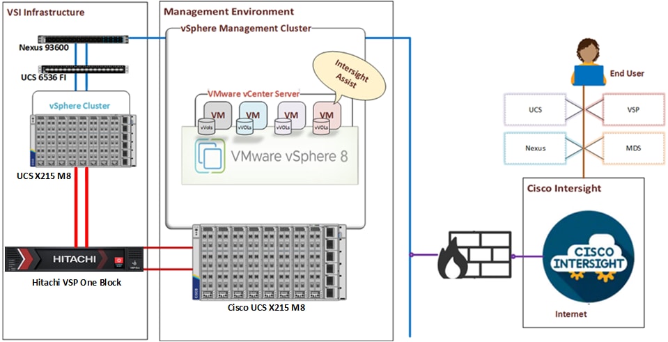
The Adaptive Solutions Virtual Server Infrastructure (VSI) is a reference architecture comprised of components and best practices from Cisco and Hitachi.
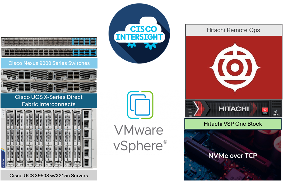
The Cisco and Hitachi components used in Adaptive Solutions designs have been validated within this reference architecture so customers have a relevant example they can use to explicitly deploy in their environment or adjust as needed within the respective product compatibility lists of Cisco and Hitachi. The best practices are intended to be relevant across supported product families, but deployment steps may differ when using supported components other than those shown in this design. Each of the component families shown in Figure 1 (Cisco UCS, Cisco Nexus, and Hitachi VSP) offers platform and resource options to scale up or scale out the infrastructure while supporting the same features.
The Adaptive Solutions hardware in this design is built with the following components:
● Cisco UCS X9508 Chassis with Cisco UCS X-Series Direct Fabric Interconnect and up to eight Cisco UCS X215c M8 Compute Nodes.
● High-speed Cisco NX-OS-based Nexus 93600CD-GX switching design to supporting 100GE connectivity with up to 400GE uplink connections.
● Hitachi VSP One Block series storage systems are positioned as a scalable storage solution for the midrange segment. Built on more than 58 years of Hitachi engineering expertise and innovation in the IT sector, the VSP One Block series delivers superior performance, resiliency, and agility. It is backed by industry’s first and most comprehensive 100 percent data availability guarantee, ensuring unmatched reliability for business critical workloads.
The software components of the solution consist of:
● Cisco Intersight platform to deploy the Cisco UCS components and maintain and support the infrastructure.
● Cisco Intersight Assist Virtual Appliance to help connect Hitachi VSP, Cisco Nexus switches, and VMware vCenter to Cisco Intersight, giving visibility and management capabilities to these elements.
● Hitachi VSP One Block Administrator provides an integrated interface to configure and manage the Hitachi VSP One Block system.
● Hitachi Vantara VSP One Block Storage Modules for Red Hat Ansible enables management and automation through Ansible playbooks and modules.
● Hitachi Remote Ops continuously monitors Hitachi solutions, generates alerts, collects operational data, and provides analytics to customers.
● VMware vSphere 8.0 U3 to incorporate new features to the release, along which Intersight will incorporate a new plugin for vCenter.
● VMware vCenter to set up and manage the virtual infrastructure as well as Cisco Intersight integration.
Cisco Unified Computing System X-Series
The Cisco UCS X-Series Modular System is designed to take the current generation of the Cisco UCS platform to the next level with its future-ready design and cloud-based management. Decoupling and moving the platform management to the cloud allows Cisco UCS to respond to customer feature and scalability requirements in a much faster and efficient manner. Cisco UCS X-Series state of the art hardware simplifies the data-center design by providing flexible server options. A single server type, supporting a broader range of workloads, results in fewer different data-center products to manage and maintain. The Cisco Intersight cloud-management platform manages Cisco UCS X-Series as well as integrating with third-party devices, including VMware vCenter and Hitachi storage, to provide visibility, optimization, and orchestration from a single platform, thereby driving agility and deployment consistency.
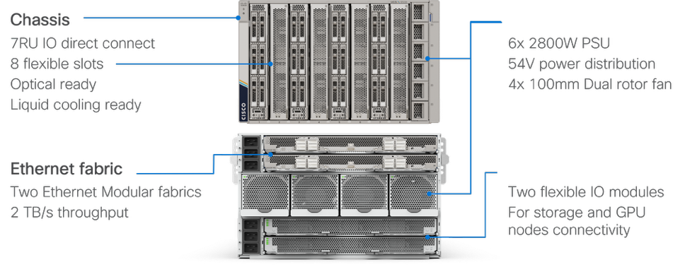
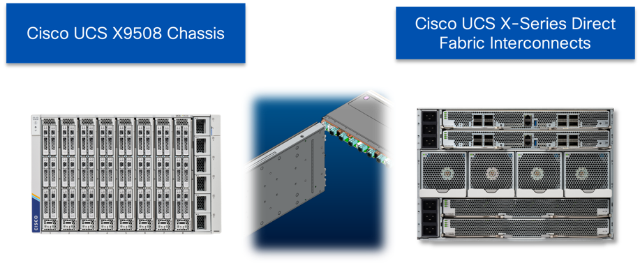
Cisco UCS X9508 Chassis
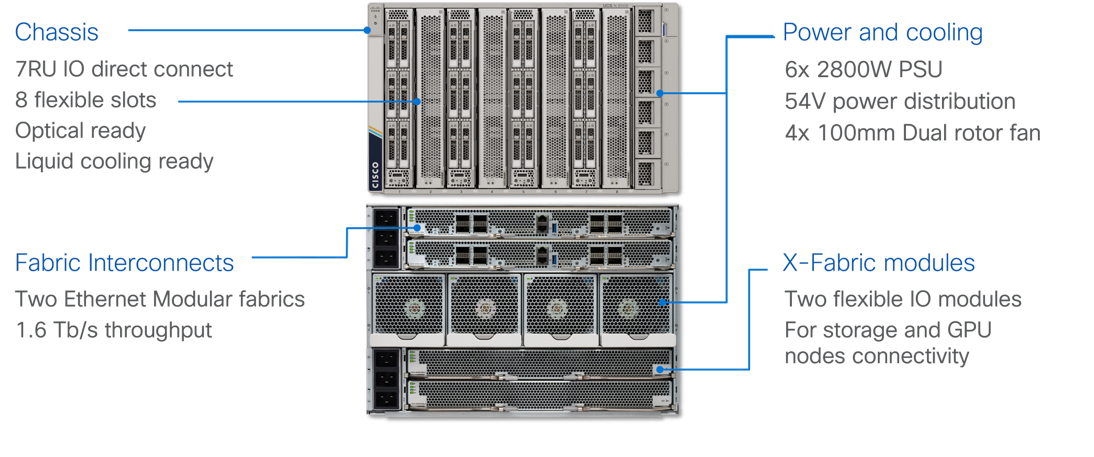
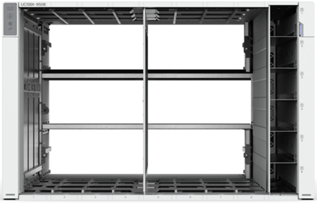
The Cisco UCS X-Series chassis is engineered to be adaptable and flexible. As shown in Figure 3, the Cisco UCS X9508 chassis has only a power-distribution midplane. This midplane-free design provides fewer obstructions for better airflow. For I/O connectivity, vertically oriented compute nodes intersect with horizontally oriented fabric modules, allowing the chassis to support future fabric innovations. Cisco UCS X9508 Chassis’ superior packaging enables larger compute nodes, thereby providing more space for actual compute components, such as memory, GPU, drives, and accelerators. Improved airflow through the chassis enables support for higher power components, and more space allows for future thermal solutions (such as liquid cooling) without limitations.
The Cisco UCS X9508 7-Rack-Unit (7RU) chassis has eight flexible slots. These slots can house a combination of compute nodes and a pool of current and future I/O resources that includes GPU accelerators, disk storage, and nonvolatile memory. At the top rear of the chassis are either the X-Series Direct Fabric Interconnects or two Intelligent Fabric Modules (IFMs) that connect the chassis to upstream Cisco UCS 6400/6500 Series or X-Series Direct Fabric Interconnects. At the bottom rear of the chassis are slots to house X-Fabric modules that can flexibly connect the compute nodes with I/O devices. Six 2800W Power Supply Units (PSUs) provide 54V power to the chassis with N, N+1, and N+N redundancy. A higher voltage allows efficient power delivery with less copper and reduced power loss. Efficient, 100mm, dual counter-rotating fans deliver industry-leading airflow and power efficiency, and optimized thermal algorithms enable different cooling modes to best support the customer’s environment.
Cisco UCS X-Series Direct Fabric Interconnects
The Cisco UCS X-Series Direct Fabric Interconnects provides a lossless and deterministic converged fabric for management, Ethernet, and storage connectivity for the Cisco UCS X-Series Modular System. This fabric interconnect is positioned within the horizontally oriented slots in the rear of the X9508 chassis, connecting within the chassis to the vertically oriented compute nodes providing control and configuration of the servers though Intersight, I/O and a unified fabric for Ethernet and Fibre Channel. This unified fabric supports 8/16/32 G FC through its first two ports, or up to 100G Ethernet on each of the 8 QSFP ports, uplinking to the LAN/SAN network, as appliance ports, or storage ports as needed.
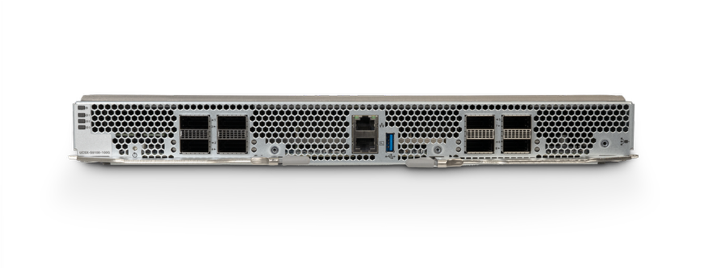
This smaller form factor residing in the X9508 chassis provides direct connectivity to the top-of-rack switch and the simplified design makes it a strong candidate for placement at the edge or branch. Manageable through classic Cisco UCS Manager, it stands out when managed through Intersight, giving common configuration and management across displaced locations, or as unified modular building blocks in a data center.
Cisco UCS 9108-100G Intelligent Fabric Modules
In design options not using the X-Series Direct Fabric Interconnect that instead prefer to use the Cisco UCS 6536 Fabric Interconnects for connecting and managing the Cisco UCS X9508 Chassis, the network connectivity can be provided by a pair of Cisco UCS 9108-100G Intelligent Fabric Modules (IFMs). Like the fabric extenders used in the Cisco UCS 5108 Blade Server Chassis, these modules carry all network traffic to the Fabric Interconnects. IFMs also host the Chassis Management Controller (CMC) for chassis management. In contrast to systems with fixed networking components, Cisco UCS X9508’s midplane-free design enables easy upgrades to new networking technologies as they emerge making it straightforward to accommodate new network speeds or technologies in the future.
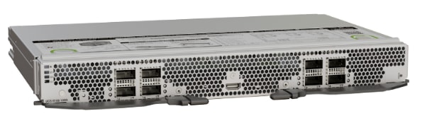
Each IFM supports eight 100Gb uplink ports for connecting the Cisco UCS X9508 Chassis to the FIs and 8 100Gb server ports for the eight compute nodes. IFM server ports can provide up to 200 Gbps of unified fabric connectivity per compute node across the two IFMs. The uplink ports connect the chassis to the Cisco UCS FIs, providing up to 1600Gbps connectivity across the two IFMs. The unified fabric carries management, VM, and Fibre Channel over Ethernet (FCoE) traffic to the FIs, where management traffic is routed to the Cisco Intersight cloud operations platform, FCoE traffic is forwarded to either native Fibre Channel interfaces through unified ports on the FI (to Cisco MDS switches) or to FCoE uplinks (to Cisco Nexus switches supporting SAN switching), and data Ethernet traffic is forwarded upstream to the data center network (via Cisco Nexus switches).
Cisco UCS X215c M8 Compute Node
The Cisco UCS X9508 Chassis can host up to 8 Cisco UCS X215c M8 Compute Nodes. The hardware details of the Cisco UCS X215c M8 Compute Nodes are shown in Figure 7.
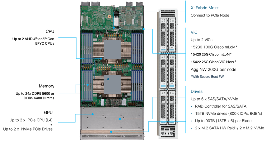
The Cisco UCS X215c M8 features:
● CPU: Up to 2x 4th or 5th Gen AMD EPYCTM Processors with up to 160 cores per processor and up to 384 MB Level 3 cache per CPU.
● Memory: Up to 6TB of main memory with 24x 256 GB DDR5 6000 MT/s or DDR5 4800 MT/s DIMMs depending on the CPU installed.
● Disk storage: Up to six hot-pluggable, SSDs, or NVMe 2.5-inch drives with a choice of enterprise-class RAIDs or passthrough controllers, up to two M.2 SATA drives with optional hardware RAID or up to two M.2 NVMe drives in pass-through mode
● Virtual Interface Card (VIC): Up to 2 VICs including an mLOM Cisco UCS VIC 15230 (100Gbps) or an mLOM Cisco UCS VIC 15420 (50Gbps) and a mezzanine Cisco UCS VIC card 15422 can be installed in a Compute Node to pair with and extend the connectivity of the Cisco UCS VIC 15420 adapter.
● Security: The server supports an optional Trusted Platform Module (TPM). Additional security features include a secure boot FPGA and ACT2 anti-counterfeit provisions.
Cisco UCS VIC 15230
Cisco UCS VIC 15230 fits the mLOM slot in the Cisco UCS X215c or X210c Compute Node and enables up to 100 Gbps of unified fabric connectivity to each of the chassis X-Series Direct or IFM for a total of 200 Gbps of connectivity per server. Cisco UCS VIC 15230 connectivity to the IFM and up to the fabric interconnects is delivered through 100Gbps. Cisco UCS VIC 15230 supports 512 virtual interfaces (both FCoE and Ethernet) capable of providing 100Gbps, along with the latest networking innovations including NVMeoF over FC or TCP, VxLAN/NVGRE offload, and secure boot technology.
Cisco UCS 6536 Fabric Interconnects
The Cisco UCS Fabric Interconnects (FIs) provide a single point for connectivity and management for the entire Cisco UCS system. Typically deployed as an active/active pair, the system’s FIs integrate all components into a single, highly available management domain controlled by Cisco Intersight or Cisco UCS Manager. Cisco UCS FIs provide a single unified fabric for the system, with low-latency, lossless, cut-through switching that supports LAN, SAN, and management traffic using a single set of cables.
This single RU device includes up to 36 10/25/40/100 Gbps Ethernet ports, 16 8/16/32-Gbps Fibre Channel ports using 4 128 Gbps to 4x32 Gbps breakouts on ports 33-36. All 36 ports support breakout cables or QSA interfaces. The Cisco UCS 6536 Fabric Interconnects are valid within the Adaptive Solutions architecture but are not featured within this design.
The Cisco Intersight platform is a Software-as-a-Service (SaaS) infrastructure lifecycle management platform that delivers simplified configuration, deployment, maintenance, and support. The Cisco Intersight platform is designed to be modular, so you can adopt services based on their individual requirements. The platform significantly simplifies IT operations by bridging applications with infrastructure, providing visibility and management from bare-metal servers and hypervisors to serverless applications, thereby reducing costs, and mitigating risk. This unified SaaS platform uses a unified Open API design that natively integrates with third-party platforms and tools.
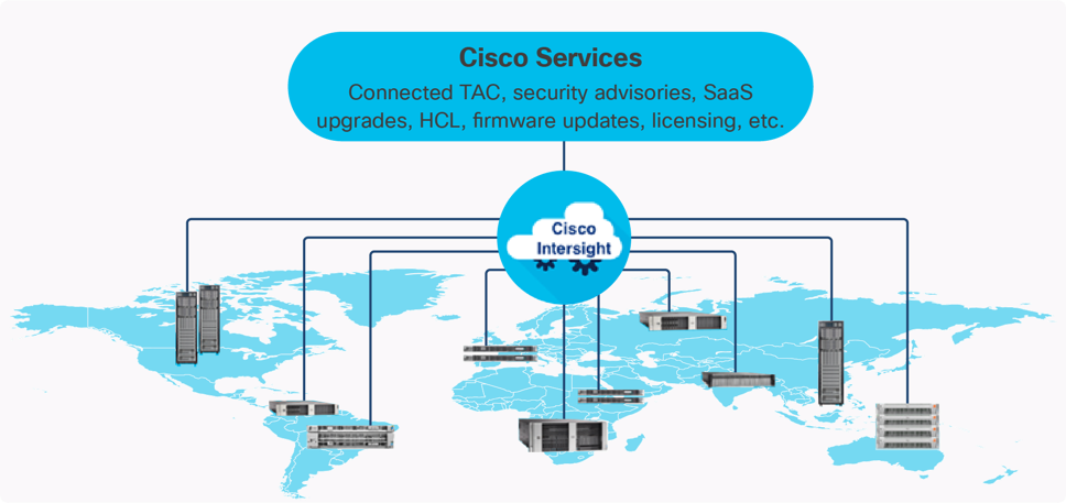
The main benefits of Cisco Intersight infrastructure services are as follows:
● Stay ahead of problems with global visibility and accelerate trouble resolution through proactive support capabilities.
● Provide role based access control (RBAC) to resources within the data center through a single platform.
● Intersight Cloud Orchestrator (ICO) provides a task based “low code” workflow approach to executing storage operations with Hitachi VSP One Block.
● Combine the convenience of a SaaS platform with the capability to connect from anywhere and manage infrastructure through a browser or mobile app.
● Elimination of silos for managing datacenter ecosystem as all components, including Hitachi storage can be managed via Intersight.
● Upgrade to add workload optimization and Kubernetes services when needed.
Cisco Intersight Virtual Appliance and Private Virtual Appliance
In addition to the SaaS deployment model running on Intersight.com, on-premises options can be purchased separately. The Cisco Intersight Virtual Appliance and Cisco Intersight Private Virtual Appliance are available for organizations that have additional data locality or security requirements for managing systems. The Cisco Intersight Virtual Appliance delivers the management features of the Cisco Intersight platform in an easy-to-deploy VMware Open Virtualization Appliance (OVA) or Microsoft Hyper-V Server virtual machine that allows you to control the system details that leave your premises. The Cisco Intersight Private Virtual Appliance is provided in a form factor specifically designed for those who operate in disconnected (air gap) environments. The Private Virtual Appliance requires no connection to public networks or back to Cisco to operate.
Cisco Intersight Assist
Cisco Intersight Assist helps you add endpoint devices to Cisco Intersight. A data center could have multiple devices that do not connect directly with Cisco Intersight. Any device that is supported by Cisco Intersight, but does not connect directly with it, will need a connection mechanism. Cisco Intersight Assist provides that connection mechanism to include the VMware vCenter Server, Cisco Nexus switches, Cisco MDS switches, the Cisco Nexus Dashboard, and the Hitachi Virtual Storage Platform. With the Intersight Assist claiming a vCenter, it can enable the vSphere Hardware Support Manager for vSphere Lifecycle Management functions, as well as a Cisco Intersight VMware Plugin.
Cisco Intersight Assist is available within the Cisco Intersight Virtual Appliance, which is distributed as a deployable virtual machine contained within an Open Virtual Appliance (OVA) file format. More details about the Cisco Intersight Assist VM deployment configuration are described in later sections.
Licensing Requirements
The Cisco Intersight platform uses a subscription-based license with multiple tiers. You can purchase a subscription duration of one, three, or five years and choose the required Cisco UCS server volume tier for the selected subscription duration. You can purchase any of the following higher-tier Cisco Intersight licenses using the Cisco ordering tool:
● Cisco Intersight Essentials: Essentials offers comprehensive monitoring and inventory visibility across global locations, UCS Central Software and Cisco Integrated Management Controller (IMC) supervisor entitlement, policy-based configuration with server profiles, firmware management, Connected TAC with Proactive RMAs, and evaluation of compatibility with the Cisco Hardware Compatibility List (HCL).
● Cisco Intersight Advantage: Advantage offers all the features and functions of the Essentials tier. It includes storage widgets and cross-domain inventory correlation across compute, storage, and virtual environments (VMware ESXi). It also includes OS installation for supported Cisco UCS platforms and Intersight Orchestrator for orchestration across Cisco UCS and third party systems.
Servers in the Cisco Intersight Managed Mode require at least the Essentials license. For more information about the features provided in the various licensing tiers, see https://intersight.com/help/getting_started#licensing_requirements.
Cisco Hardware Support Manager
The Cisco Hardware Support Manager (HSM) service option enabled with vSphere Lifecycle Manager (vLCM) plug-in allows you to update the Operating System and perform firmware upgrades simultaneously with a single firmware image. The HSM is integrated with Cisco Intersight Infrastructure Service, which enables you to manage your vCenter server instance.
The Cisco Nexus 9000 Series Switches offer both modular and fixed 1/10/25/40/100/400 Gigabit Ethernet switch configurations with scalability up to 115 Tbps of nonblocking performance with less than five-microsecond latency, wire speed VXLAN gateway, bridging, and routing support.
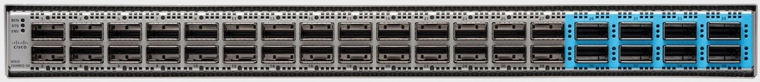
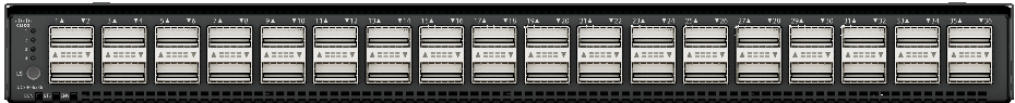
The Cisco Nexus 9000 series switch featured in this design is the Cisco Nexus 93600CD-GX configured in NX-OS standalone mode. NX-OS is a purpose-built data-center operating system designed for performance, resiliency, scalability, manageability, and programmability at its foundation. It provides a robust and comprehensive feature set that meets the demanding requirements of virtualization and automation.
The Cisco Nexus 93600CD-GX Switch is a 1RU switch that supports 12 Tbps of bandwidth and 4.0 bpps across 28 fixed 40/100G QSFP-28 ports and 8 fixed 10/25/40/50/100/200/400G QSFP-DD ports. Breakout supported on ports, 25-36: 2x200, 4x100, 2x100, 8x50, 4x50, 2x50, 4x25, 4x10, and 10G w/QSA. This switch was chosen for this solution because of its robust uplink capabilities in a 1RU format, and future-proofness of 400G capacity.
Port groups within the 93600CD-GX switches follow specific requirements when configuring breakout ports, which is explained in the hardware installation guide, here: https://www.cisco.com/c/en/us/td/docs/switches/datacenter/nexus9000/hw/n93600cd-gx-hig/guide/b_c93600cd-gx-nxos-mode-hardware-installation-guide/m_overview1.html
Hitachi Virtual Storage Platform
Hitachi VSP One Block is a highly scalable, true enterprise-class block storage system designed for mission-critical workloads. It supports virtualization of external storage and offers advanced features such as virtual partitioning and quality of service (QoS) to enable diverse workload consolidation. With the industry’s only 100% data availability guarantee, VSP One Block ensures maximum uptime and flexibility for your block-level storage needs.
Hitachi VSP One Block uses all-NVMe storage with three dedicated models supported in a 2RU configuration. All models have the same capacity (72 NVMe flash drives) and support various storage transport protocols such as NVMe over TCP, Fibre Channel (FC), and iSCSI. The NVMe flash architecture delivers consistent low-microsecond latency, reducing the transaction cost of latency-critical applications and delivering predictable performance to optimize storage resources.
The VSP One Block storage system consists of a controller chassis, one or more NVMe drive boxes, and internal components such as fans and PCIe switches.
VSP One Block capabilities eliminate complexity for end users by providing:
● Always-on Data reduction
● Dynamic Drive Protection (DDP) that removes the need for complicated RAID setups
● Dynamic Carbon Reduction, delivering measurable reductions in power consumption
The following models are available in the VSP One Block series:
● VSP One Block 24 – 256GB Cache + Software Advanced Data Reduction (ADR) + 24 cores
● VSP One Block 26 – 768GB Cache + 2x Compression Accelerator Module (CAM) + 24 cores
● VSP One Block 28 – 1TB Cache + 4x CAM + 64 cores
The Hitachi VSP One Block series builds on over 58 years of proven Hitachi engineering expertise, delivering a superior range of business continuity options, and setting the benchmark for industry-leading reliability. As a result, 85 percent of Fortune 100 financial services companies trust Hitachi storage systems with their mission-critical data.
Hitachi Storage Virtualization Operating System RF
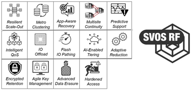
Hitachi SVOS RF (Resilient Flash) delivers best-in-class business continuity, always-on and data availability, and simplified storage management across all Hitachi VSP systems through a unified operating system.
Flash performance is optimized with a patented flash-aware I/O stack, whereas adaptive inline data reduction increases storage efficiency and balances data optimization with application performance. With industry-leading storage virtualization, SVOS RF extends the life of existing investments by incorporating third-party all-flash and hybrid arrays into a consolidated resource pool.
Hitachi SVOS RF provides the foundation for global storage virtualization by abstracting and managing heterogeneous storage into a single, unified virtual storage layer. This software-defined storage approach enables resource pooling, automation, self-optimization, and centralized management, delivering higher utilization and improved operational efficiency. Optimized for flash, SVOS RF maintains consistently low response times as data volumes grow, and selectable data-reduction technologies to be activated based on workload benefit.
SVOS RF also integrates with Hitachi base and advanced software packages to deliver:
● Superior availability and operational efficiency
● Active-active clustering for continuous availability
● Data-at-rest encryption for security
● AI and machine learning-driven insights for intelligent operations
● Policy-defined data protection with local and remote replication.
For more information about Hitachi Storage Virtualization Operating System RF, see: https://www.hitachivantara.com/en-us/products/storage-platforms/primary-block-storage/virtualization-operating-system.html
Hitachi VSP One Block Series Key Features
● High performance
◦ Multiple-controller configuration distributes processing loads across controllers.
◦ Ultra-high-speed I/O powered by NVMe flash drives with up to 1,024 GiB of cache.
◦ Network throughput options: 100Gbps NVMe/TCP, 64Gb FC, and 25Gbps iSCSI.
◦ Hardware acceleration for high-performance compression.
◦ Intel Xeon Gen 4 processors with PCIe Gen4 and Dynamic Power Reduction.
◦ Always-on compression acceleration engines and algorithms.
◦ NVMe Gen4 drive trays and Gen4 SSD media, scalable up to 72 drives.
◦ Virtual Storage Scale-Out expansion capabilities.
◦ 33% more IO slots for flexible configuration.
◦ Thin Image Advanced Data Protection and ransomware protection with Safe Snap.
● High reliability
◦ Service continuity for all main components through redundant configuration.
◦ Dynamic drive protection (DDP) utilizes dual-parity RAID 6 configurations (for example, 14D+2P). DDP is a drive distributed RAID function. DDP distributed the spare space to each drive, eliminating the need for dedicated spare drives. In addition, DDP distributes the load of rebuilding to all drivers, reducing the time for rebuilding. DDP improves usability, efficiency, and performance.
◦ Data security by automatically transferring data to non-volatile cache flash memory during a power outage without any intervention.
◦ Nondisruptive maintenance for main components enabling the storage system to remain in operational.
● Scalability and versatility
◦ VSP One B24: Scalable capacity up to 4.3 PB (internal) and 64 PiB (external).
◦ VSP One B26: Scalable capacity up to 4.3 PB (internal), 128 PiB (external).
◦ VSP One B28: Scalable capacity up to 4.3 PB (internal), 255 PiB (external).
● Manageability
◦ Integrated with Cisco Intersight to improve IT operational efficiency.
◦ Available Ansible playbooks for automated configuration and management.
◦ Integration with Hitachi VSP 360 provides a unified management platform that simplifies infrastructure operations, accelerates decision-making, and reduces time to deliver data services.
◦ Native VMware plug-ins for simplified storage management.
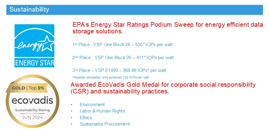
● Sustainability
◦ Hitachi's patented Dynamic Carbon Reduction (DCR) technology reduces power consumption by placing controller CPUs in low-power mode during periods of low activity.
◦ ENERGY STAR® certified and Carbon Footprint of Products (CFP) approved for environmental compliance.
◦ Modern Storage Assurance extends service lifecycles and minimizes electronic waste, enabling continued use of both current and next-generation VSP One infrastructure.
◦ The Storage Virtualization Operating System (SVOS) provides enhanced data reduction technology that increases storage efficiency, reducing power usage and CO2 emissions by up to 65% in some cases.
◦ Hitachi Vantara diagnostics and sustainability advisory services help organizations adopt effective and measurable sustainability practices.
For more information about Hitachi Virtual Storage Platform One Block Series, see https://www.hitachivantara.com/en-in/products/storage-platforms/block-storage/midrange/vsp-one-block
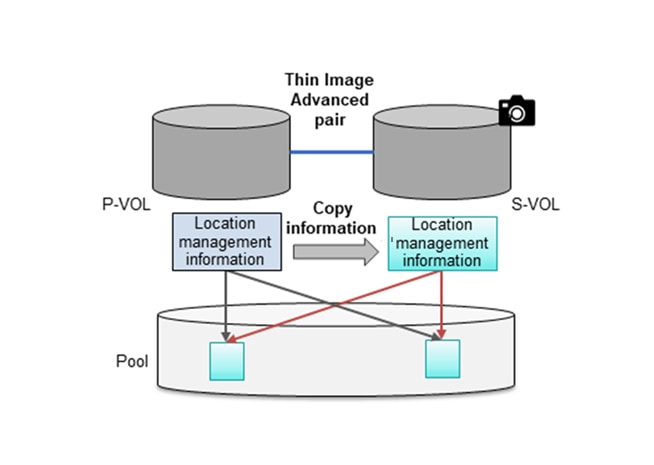
Hitachi Thin Image Provisioning Advanced
Hitachi Thin Image Advanced (HTI Advanced) enables cost-effective replication by storing only the differential data between the primary volumes (P-VOLs) and secondary volumes (S-VOLs). Snapshots are stored within Hitachi Virtual Storage Platform family (VSP family) storage system. If a logical data failure occurs in the storage system due to erroneous data update or virus infection, you can restore using the stored snapshots. Pairs created using Thin Image Advanced are called Thin Image Advanced pairs.
The nondisruptive, high-speed, snapshot technology of Hitachi Thin Image Advanced can rapidly create up to one million point-in-time copies of mission-critical data within any Hitachi storage system or virtualized storage pool, without impacting host services or performance levels. Because snapshots store only changed data, the storage capacity required is greatly reduced, resulting in significant savings compared to full-volume cloning. Snapshot copies are fully read/write compatible with other hosts and can be used for backups, application testing, or data mining while production workloads continue uninterrupted.
● Creates up to 1,024 instant point-in-time copies for data protection or testing.
● Saves up to 90% or more disk space by storing only changed data blocks.
● Reduces backup times from hours to minutes, minimizing backup windows.
● Provides near-instant restoration of critical data for increased business continuity.
● Application-and OS-independent, with optional integration to application backup triggers.
● Delivers fast, simple, and reliable snapshot management.
Hitachi Thin Image Advanced (TIA) is not part of this design, information provided here is for reference of its capabilities. For more information about Hitachi Thin Image Advanced, see: https://docs.hitachivantara.com/r/en-us/svos/9.8.7/mk-98rd9033/overview-of-thin-image-advanced/how-thin-image-advanced-works.
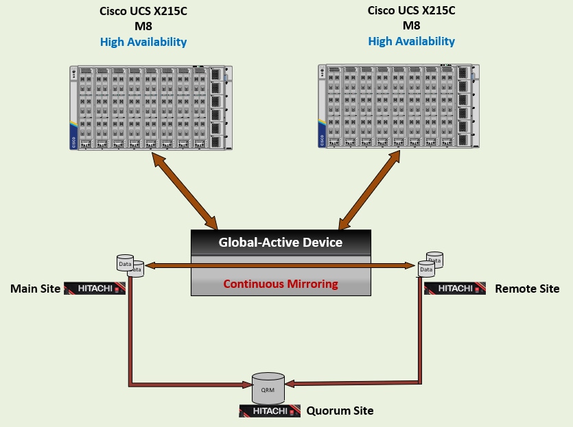
High Availability with Global-Active Device
Hitachi Global-active device enables synchronous, remote copies of data volumes for continuous availability. A Virtual Storage Machine (VSM) is configured in both primary and secondary storage systems, using the actual information of the primary system. The Global-active device primary and secondary volumes are assigned the same logical device (LDEV) number in the VSM, enabling the host to see the pair volumes as a single volume on a single storage system, and both volumes receive the same data from the host to view and access them as a single volume. Both volumes receive identical data from the host.
A quorum disk hosted on a third and external storage system or in an iSCSI-attached host acts as a heartbeat mechanism. Both storage systems access the quorum disk to monitor each other. In the event of a communication failure, the quorum disk helps identify the issue and ensures the system can continue to receive host updates without disruption.
Global-active device automates high availability by full metro clustering by providing full metro clustering between data centers located up to 500 km apart. Its active-active design supports read/write copies of the same data in two locations simultaneously. Cross-mirrored storage volumes between VSP systems safeguard mission-critical data and ensure uninterrupted access for host applications, even during site or storage system failures. This ensures that up-to-date, consistent data is always available and enables production workloads to run on both systems concurrently.
For VSP One Block support for the GAD feature, see https://docs.hitachivantara.com/r/en-us/svos/10.4.x/mk-23vsp1b011/overview-of-global-active-device/global-active-device-components.
VMware High Performance Plug-In (HPP) on the host operates in an Active/Active configuration. While this setup works well at campus distances, Asymmetric Logical Unit Access (ALUA) is required at metro distances to support optimized and non-optimized paths, ensuring that the shortest path is always used. If the host cannot access the primary volume (P-VOL) or secondary volume (S-VOL), alternate path software automatically redirects host I/O to the appropriate volume without impacting host applications.
Benefits of Global-active device volume pairs include:
● Continuous I/O: If a primary volume becomes unavailable, the host continues to transparently access the secondary volume.
● Clustered failover: Storage system tasks such as suspension or resynchronization of Global-active device pairs after a host failure are not required.
● Host load balancing: Workloads creating high demand at one site can be shifted to the other site.
● High performance: Multipath software allows application access to mirrored data through the shortest path for maximum performance.
● Workload mobility: Concurrent data mirroring makes data immediately available to servers at a second site, even over metro distances.
● Nondisruptive data migration: Data volumes can be migrated between storage systems without disrupting normal operations.
Hitachi Global-active device is not part of this design. Information provided here is for reference only. For more information about High availability with Global-active device with Cisco UCS, see https://www.cisco.com/c/en/us/td/docs/unified_computing/ucs/UCS_CVDs/cisco_hitachi_adaptivesolutions_ci_stretcheddc.html.
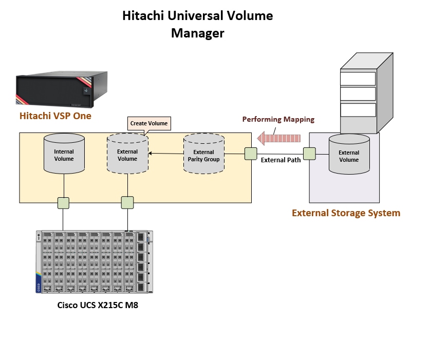
Hitachi Universal Volume Manager
Hitachi Universal Volume Manager (UVM) is a built-in capability that enables virtualization of legacy or third-party storage devices behind the Hitachi VSP. This allows all storage to be managed from a single system along with providing native VSP features to the virtualized environment.
To use volumes on the external system with the target VSP, external path connections must be established between the controllers of the external storage system and the target VSP. After physical connections are made, the volumes of the external storage system can be mapped to the target VSP.
External volumes can be used in scenarios such as:
● Backing up of target VSP storage volumes to an external storage system.
● Expanding capacity by using an external storage system through the target VSP.
● Migrating data from legacy external storage system to the new target VSP.
Figure 17 shows the components and configuration for UVM.
Hitachi UVM is not part of this design. The information provided here is for reference only. For more information about Hitachi UVM, see https://docs.hitachivantara.com/v/u/en-us/application-optimized-solutions/mk-sl-272.
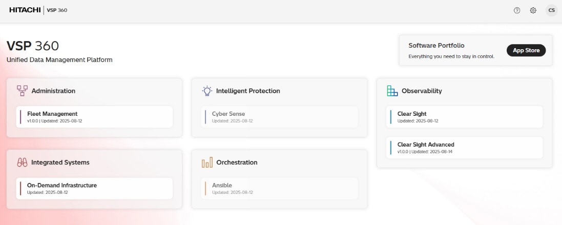
Hitachi VSP 360
Hitachi VSP 360 is a unified management platform that simplifies data infrastructure management operations, improves decision-making, and decreases the time required to deliver data services. It enables IT teams to efficiently manage hybrid cloud environments, proactively optimize performance with AIOps-driven insights, and enforce consistent data governance across the storage lifecycle.
After installing the VSP 360 platform, you can:
● Install additional applications from the software portfolio that are not installed by default, including tools for observability, automation, and data governance.
● Add users and assign roles to control access and manage permissions across storage systems.
● Create user groups with specific roles and privileges to streamline administration and security.
The following VSP 360 applications are installed by default:
● Fleet Management: Simplifies setup, management, and maintenance of storage resources, reducing the complexity of managing storage systems. This includes adding storage systems, fabric switches, and servers. Configuring block storage, including port security, parity groups, and pools. Configuring port settings. Creating, attaching, and protecting volumes. Scheduling jobs to configure storage systems, servers, fabric switches, or virtual storage machines.
● Data Protection: Detects ransomware-related data corruption with 99.99% accuracy using advanced AI and analytics, ensuring effective cyber resiliency. Enables structured workflows that automate and manage backup, recovery, and retention tasks across complex IT environments. The client software must be installed on each server participating in the data protection environment. The VSP 360 Data Protection application serves as the primary central controller and the connection point for the user interface. Active data protection policies will continue to function with or without the primary being available because the participating Cli-ents operate autonomously using rules distributed from the primary.
● Clear Sight: Provides a unified digital experience for monitoring and managing your infrastructure.
● Clear Sight Advanced: Uses AI-powered analytics to provide insight into system health, capacity, and performance, enabling proactive optimization and issue prevention. Features range from providing administrators and stakeholders with insights to effectively manage infrastructure. Deploying probes to monitor and collect data from different devices within the storage infrastructure. Configuring resource thresholds for proactive monitoring. Navigating from high-level summaries to detailed hierarchical views for in-depth analysis. Generating advanced reports to identify risks, highlight non-compliant resources, and recommend corrective actions. Delivering actionable insights to proactively mitigate risks and resolve issues before they escalate. Analyzing port imbalances and workload placement. Analyzing and troubleshooting block storage health. Using predefined or custom reports to monitor the performance, capacity, and overall health of storage system resources.
● Hitachi EverFlex Control: Helps businesses modernize IT operations and achieve greater agility and cost efficiency.
You can install the following additional applications from the software portfolio:
● Ansible: Connects to a library of Ansible playbooks, allowing you to link and launch them from VSP 360.
● CyberSense: Enhances cyber resiliency by detecting ransomware-related data corruption with 99.99% accuracy using advanced AI and analytics.
Note: Hitachi VSP 360 is not a part of this design. The information provided here is only for reference of its capabilities. For more information about Hitachi VSP 360, see https://www.hitachivantara.com/en-us/products/data-management
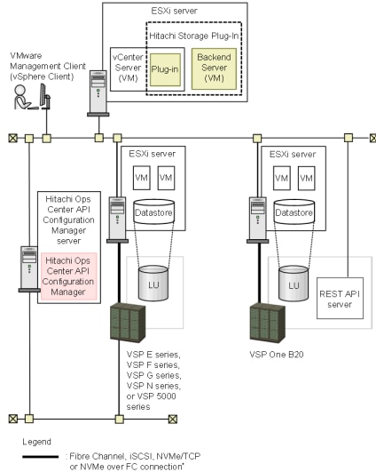
Hitachi Storage Plug-in for VMware vCenter
Hitachi Storage Plug-in for VMware vCenter integrates Hitachi storage information and provisioning operations directly into the VMware vSphere Web Client. This integration allows VMware administrators to provision and mount VMFS datastores within their familiar vSphere environment without having to engage storage administrators. By consolidating storage operations into the same interface used for virtual infrastructure tasks, administrators gain a unified, single-pane-of-glass management experience.
The plug-in provides the following capabilities:
● View: Displays storage system information registered in the storage plug-in, the datastores on ESXi hosts using the storage system, and related virtual machine information.
● Provision Datastore: Creates Logical Devices (LDEVs) that serve as datastores for Virtual Machine File System (VMFS) and Raw Device Mapping (RDM) objects using storage systems registered with the plug-in.
● Delete Datastore (or LDEV): Removes datastores or logical devices from registered storage systems in a single operation. Datastores or logical devices not created through the plug-in are not affected.
The software requires access to RAID storage system controllers over TCP/IP, whereas VMware ESXi servers must have connectivity to the storage systems through TCP/IP or Fibre Channel. For more information about the validation of the Hitachi Storage Plug-in for VMware vCenter, see the deployment guide.
Hitachi Storage Plug-in for VMware vCenter is not a part of this design; the information provided here is for reference of capabilities. For more interoperability support details about the Hitachi Storage Plug-in for VMware vCenter, see: https://docs.hitachivantara.com/v/u/en-us/adapters-and-drivers/4.12.x/mk-92adptr047.
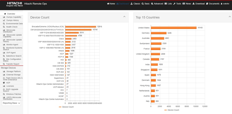
Hitachi Remote Ops is a monitoring system that provides continuous access to the full spectrum of Hitachi’s Global Support Center infrastructure and expertise, while meeting security requirements to protect your environment.
Remote Ops s performs regular health checks, analyzes errors and automatically opens cases when needed. This allows Hitachi Vantara experts to proactively contact you, provide performance improvement guidance, and remotely fine-tune your environment all while ensuring that your data remains secure.
Hitachi Remote Ops monitoring system is not covered within the subsequent deployment guide, as it is enabled by default with every Hitachi VSP as part of professional services. For more information, see https://www.hitachivantara.com/en-us/pdf/datasheet/remote-ops-monitoring-system-datasheet.pdf.
VMware vSphere is the enterprise workload platform that extends the benefits of cloud to on-premises workloads. It aggregates the infrastructure of an entire data center into a unified platform with resources that can be allocated quickly and dynamically to any application as needed.
VMware vSphere 8.0 Update 3g is validated in this release and introduces several advancements, including:
● DPU/SmartNIC support
● Virtual Machine Management with enhanced shutdown policies
● Memory Tiering with NVMe devices as tiered memory
● vSphere Lifecycle Manager with parallel hardware and firmware remediation
● vSphere Configuration Profiles supporting VDS configurations at the cluster level
For the complete list of features enabled by VMware vSphere 8.0 U3g, see the release notes: https://techdocs.broadcom.com/us/en/vmware-cis/vsphere/vsphere/8-0/release-notes/vcenter-server-update-and-patch-release-notes/vsphere-vcenter-server-80u3g-release-notes.html.
VMware vCenter Server
VMware vCenter Server provides centralized management of all hosts and virtual machines (VMs) through a single HTML5-based web client. It aggregates performance monitoring across clusters, hosts, and VMs giving administrators deep visibility into the status and configuration of compute clusters, hosts, VMs, storage, guest operating system, and other critical components of a virtual infrastructure.
VMware vCenter Server manages the full range of VMware vSphere features and integrates with third-party infrastructure, including solutions from Cisco and Hitachi.
Solution Design
This chapter contains the following:
● Physical End-to-End Connectivity
● Cisco UCS X-Series Configuration - Cisco Intersight Managed Mode
● Hitachi VSP One Block Design
● VMware vSphere - ESXi Design
● Cisco Intersight Integration with VMware vCenter, Hitachi Storage, and Cisco Switches
● Security
The Adaptive Solutions architecture delivers a cloud-managed infrastructure solution on the latest Cisco UCS hardware featuring the Cisco UCS X-Series Direct Fabric Interconnect and the Cisco UCS X215c M8 Compute nodes. The VSI architecture is built to deliver the VMware vSphere 8.0 U3 hypervisor installed to local M.2 drives with the Hitachi VSP providing the storage infrastructure serving high performance NVMe/TCP block storage for the application access. The Cisco Intersight cloud-management platform is utilized to configure and manage the infrastructure, with visibility at all layers of the architecture. Refer to the following document: Hitachi Virtual Storage Platform with Cisco Intersight Cloud Orchestrator - Best Practices Guide for additional information for provisioning storage.
This release of the Adaptive Solutions architecture uses a 100G end-to-end Ethernet design available for the storage access and the compute layer for supporting the application. In this design, the Hitachi VSP One Block and the Cisco UCS X-Series are connected through Cisco Nexus 93600CD-GX Switches for application and storage needs, with boot established through local M.2 drives configured in RAID 1.
The physical connectivity details of the topology are shown in Figure 20.
To validate the configuration, the components are set up as follows:
● Cisco UCS X-Series Direct Fabric Interconnects provide the chassis and network connectivity.
● The Cisco UCS X-Series Direct Fabric Interconnects reside directly within the X9508 Chassis with two 100 Gigabit Ethernet ports going upstream to the 93600CD-GX switches. If additional bandwidth is required, up to eight 100G ports can be utilized to these fabric interconnects.
● Cisco UCS X215c M8 Compute Nodes contain the fifth-generation Cisco 15230 virtual interface cards (VICs) delivering up to 100G from each side of the fabric as the servers physically connect directly to the fabric interconnects within the chassis.
● Cisco Nexus 93600CD-GX Switches in Cisco NX-OS mode provide the switching fabric and connect to each of the Cisco UCS X-Series Direct in a Virtual Port Channel (vPC) configuration.
● The Hitachi VSP One Block is connected to the Cisco Nexus 93600CD-GX switches through multiple 100Gbps Ethernet links, providing high-performance NVMe/TCP connectivity.
● VMware 8.0 U3 ESXi software is installed on Cisco UCSX-215c M8 Compute Nodes to validate the infrastructure.
In the Adaptive Solutions deployment, each Cisco UCS server equipped with a Cisco Virtual Interface Card (VIC) is configured for multiple virtual Network Interfaces (vNICs), which appear as standards-compliant PCIe endpoints to the OS. The end-to-end logical connectivity delivers multi-pathing for the VLAN connectivity between the server profile for an ESXi host and the storage configuration on the Hitachi VSP One Block is described below.
Figure 21 illustrates the end-to-end connectivity design.
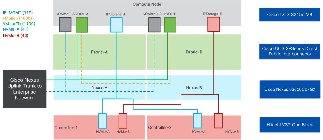
Each ESXi server profile supports:
● Managing the ESXi hosts using a common management segment
● The vNICs are:
◦ Two redundant vNICs (vSwitch0-A and vSwitch0-B) carry the management VLAN which is pinned to fabric A to keep ESXi management traffic primarily within fabric A. The MTU value for these vNICs is set as a Jumbo MTU (9000), but management interfaces with MTU 1500 can be placed on these vNICs.
◦ Two redundant vNICs (vDS0-A and vDS0-B) are used by vDS0 and carry VMware vMotion traffic and customer application data traffic. Like the management traffic, the vMotion traffic is pinned to fabric B to keep it contained within fabric B. The MTU for the vNICs is set to Jumbo MTU (9000), but interfaces that require MTU 1500 can be placed on these vNICs.
◦ Two redundant vNICs (IPStorage-A and IPStorage-B) are configured for the NVMe over TCP traffic from the VSP One Block targets to the compute node initiators. The pathing is split over a SAN type fabric to allow for traffic to persist to each controller in the event of a switch failure.
VLAN Configuration
Table 1 lists VLANs configured for setting up the environment along with their usage.
| VLAN ID |
Name |
Usage |
| 2 |
Native-VLAN |
Use VLAN 2 as native VLAN instead of default VLAN (1) |
| 41 |
NVMe-A |
NVMe over TCP traffic carried over the A side of the fabric |
| 42 |
NVMe-B |
NVMe over TCP traffic carried over the B side of the fabric |
| 119 |
IB-MGMT-VLAN |
In-band management VLAN utilized for all in-band management connectivity - for example, ESXi hosts, VM management, and so on. |
| 1000 |
vMotion |
VMware vMotion traffic |
| 1100 |
VM-Traffic |
VM data traffic VLAN |
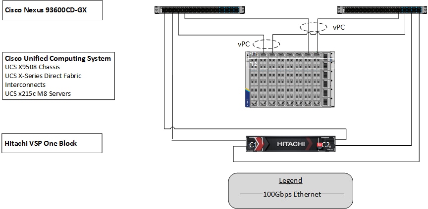
Physical End-to-End Connectivity
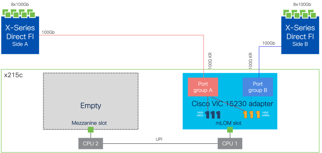
The physical end-to-end connectivity specific to the storage traffic is shown in Figure 22. The server to fabric interconnect connection that the VICs participate in is a direct physical connection of KR links between the compute nodes and the UCS X-Series Direct Fabric Interconnects.
Leaving the FIs, the traffic is carried within a pair of port channels that are received across the upstream Nexus as two separate Virtual Port Channels (vPC) that each Nexus will participate in. Leaving the Nexus to the VSP, there is a fabric preference of the A side carried through the Nexus A side switch and a B fabric preference within the Nexus B side switch as it proceeds to the VSP. In a configuration enabled with more CHB adapter ports on the VSP One Block, it would be possible to present both A and B NVMe over TCP traffic on each switch, but it was left as a single fabric priority to allow for both controllers to remain engaged in the event of a switch failure with the number of ports available.
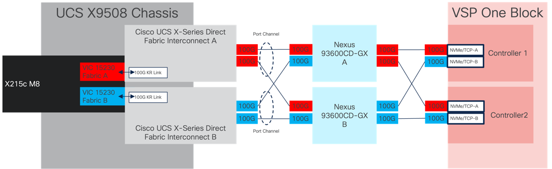
The specific connections as the storage traffic flows from a Cisco UCS X215c M8 server in a UCS environment to Hitachi VSP One Block system is as follows:
● Each Cisco UCS X215c M8 server is equipped with a Cisco UCS VIC 15230 adapter that connects to each fabric at a link speed of 100Gbps that are configured with Ethernet adapter policies maximized for IP storage traffic.
● The link from the Cisco UCS VIC 15230 is physically connected into the Cisco UCS X-Series Direct FI as they both reside in the Cisco UCS X9508 chassis.
● Coming from the Fis, the traffic is configured as port-channels to each FI that is configured across each Nexus 93600CD-GX switch as a virtual port channel.
● From the Nexus switch it is received by the CHB adapter ports of the Hitachi VSP One Block controller ports which are configured as NVMe over TCP targets to serve the block storage resources.
This connectivity also includes upstream connectivity out of the Nexus 93600CD-GX switches that is not pictured.
The Cisco UCS X9508 Chassis is equipped with the Cisco UCS X-Series Direct Fabric Interconnects. These fabric interconnects take the place within the chassis that is otherwise holding a Cisco UCS Intelligent Fabric Module (IFM) that would be used to connect to a 4th or 5th generation fabric interconnect. The X-Series Direct FI serves the function of the fabric interconnect, but also the direct connection to the compute nodes that was previously handled by the IFM, as shown in Figure 23.
The Cisco Nexus 93600CD-GX device configuration covers the core networking requirements for Layer 2 and Layer 3 communication. Some of the key NX-OS features implemented within the design are:
● Feature interface-vans—Allows the VLAN IP interfaces to be configured within the switch as gateways.
● Feature HSRP—Allows the Hot Standby Routing Protocol configuration for high availability.
● Feature LACP—Allows the utilization of Link Aggregation Control Protocol (802.3ad) by the port channels configured on the switch.
● Feature VPC—Virtual Port-Channel (vPC) presents the two Nexus switches as a single “logical” port channel to the connecting upstream or downstream device.
● Feature LLDP—Link Layer Discovery Protocol (LLDP), a vendor-neutral device discovery protocol, allows the discovery of both Cisco devices and devices from other sources.
● Feature NX-API—NX-API improves the accessibility of CLI by making it available outside of the switch by using HTTP/HTTPS. This feature helps with configuring the Cisco Nexus switch remotely using the automation framework.
● Feature UDLD—Enables unidirectional link detection for various interfaces.
Cisco UCS X-Series Direct Fabric Interconnect to Cisco Nexus 93600CD-GX Ethernet Connectivity
Cisco UCS X-Series Direct FIs are connected with port channels to Cisco Nexus 93600CD-GX switches using 100GE connections configured as virtual port channels. Each FI is connected to both Cisco Nexus switches using a 100G connection; additional links can easily be added to the port channel to increase the bandwidth as needed. Figure 38 illustrates the physical connectivity details.
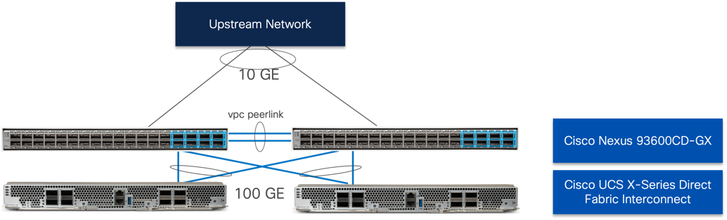
Upstream connections for the Cisco Nexus 93600CD-GX can support up to 400G links, however for the validated environment, 10G connections were used with QSA modules.
Hitachi VSP One Block to Nexus 93600CD-GX Connectivity
For NVMe over TCP delivery, each Hitachi VSP One Block controller is connected to both Cisco Nexus 93600CD-GX switches using redundant 100GE connections, as shown in Figure 25.
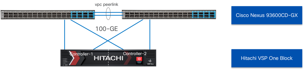
This dual-switch, dual-controller connectivity design ensures high availability and resiliency. In the event of a switch or compute fabric failure, traffic is seamlessly handled by the alternate paths, maintaining uninterrupted NVMe/TCP access to the storage system..
Cisco UCS X-Series Configuration - Cisco Intersight Managed Mode
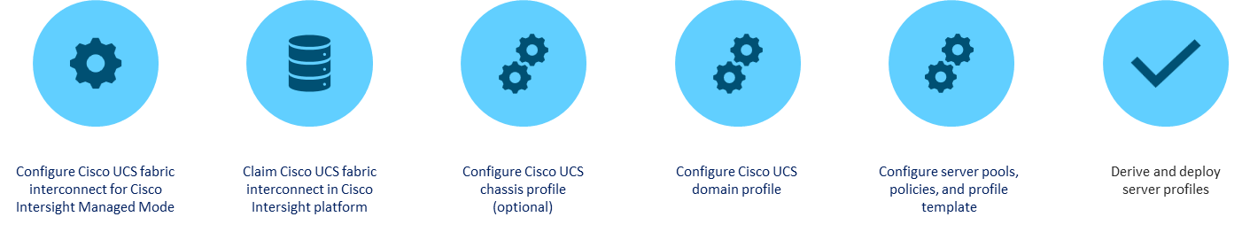
Cisco Intersight Managed Mode continues to standardize policy and operation management with the UCS X-Series Direct for Cisco UCS X-Series compute nodes used in this CVD. The Cisco UCS compute nodes are configured using server profiles defined in Cisco Intersight. These server profiles derive all the server characteristics from various policies and templates. At a high level, configuring Cisco UCS using Intersight Managed Mode consists of the steps shown in Figure 26.
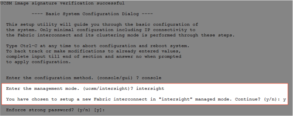
Set up Cisco UCS Fabric Interconnect for Cisco Intersight Managed Mode
During the initial configuration, for the management mode the configuration wizard enables customers to choose whether to manage the fabric interconnect through Cisco UCS Manager or the Cisco Intersight platform. Customers can switch the management mode for the fabric interconnects between Cisco Intersight and Cisco UCS Manager at any time; however, Cisco UCS FIs must be set up in Intersight Managed Mode (IMM) for configuring the Cisco UCS X-Series system and the Cisco UCS X-Series Direct fabric interconnects. Figure 27 shows the dialog during initial configuration of Cisco UCS FIs for setting up IMM.
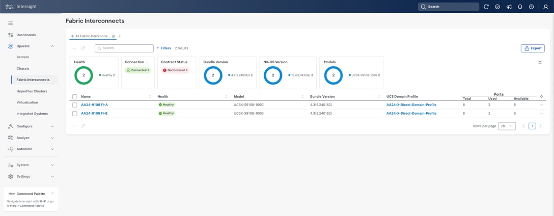
Claim a Cisco UCS Fabric Interconnect in the Cisco Intersight Platform
After setting up the Cisco UCS fabric interconnect for Cisco Intersight Managed Mode, FIs can be claimed to a new or an existing Cisco Intersight account. When a Cisco UCS fabric interconnect is successfully added to the Cisco Intersight platform, all future configuration steps are completed in the Cisco Intersight portal.
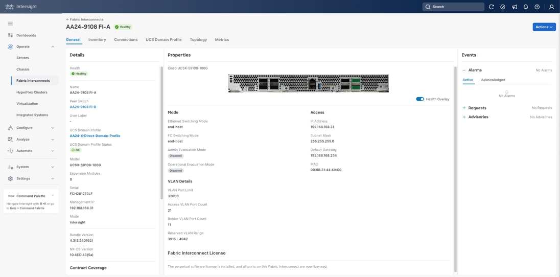
You can verify whether a Cisco UCS fabric interconnect is in Cisco UCS Manager managed mode or Cisco Intersight Managed Mode by clicking the fabric interconnect name and looking at the detailed in-formation screen for the FI, as shown in Figure 29.
Cisco UCS Chassis Profile (Optional)
A Cisco UCS Chassis profile configures and associate chassis policy to an IMM claimed chassis. The chassis profile feature is available in Intersight only if customers have installed the Intersight Essentials License. The chassis-related policies can be attached to the profile either at the time of creation or later.
The chassis profile is used to set the power policy for the chassis. By default, Cisco UCS X-Series power supplies are configured in GRID mode, but the power policy can be utilized to set the power supplies in non-redundant or N+1/N+2 redundant modes.
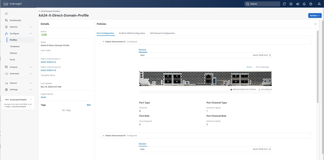
Cisco UCS Domain Profile
A Cisco UCS domain profile configures a fabric interconnect pair through reusable policies, allows configuration of the ports and port channels, and configures the VLANs and VSANs to be used in the network. It defines the characteristics of and configures the ports on the fabric interconnects. One Cisco UCS domain profile can be assigned to one fabric interconnect domain, which will be associated with one port policy per Cisco UCS domain profile.
Some of the characteristics of the Cisco UCS domain profile in the environment are:
● A single domain profile is created for the pair of Cisco UCS fabric interconnects.
● Unique port policies are defined for the two fabric interconnects.
● The VLAN configuration policy is common to the fabric interconnect pair because both fabric interconnects are configured for the same set of VLANs.
● The VSAN configuration policies are unique for the two fabric interconnects because the VSANs are unique.
● The Network Time Protocol (NTP), network connectivity, Link Control (UDLD), and system Quality-of-Service (QoS) policies are common to the fabric interconnect pair.
After the Cisco UCS domain profile has been successfully created and deployed, the policies including the port policies are pushed to the Cisco UCS fabric interconnects. The Cisco UCS domain profile can easily be cloned to install additional Cisco UCS systems. When cloning the UCS domain profile, the new UCS domains utilize the existing policies for consistent deployment of additional Cisco UCS systems at scale.
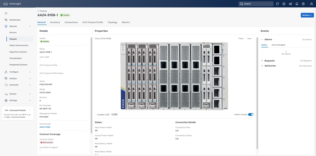
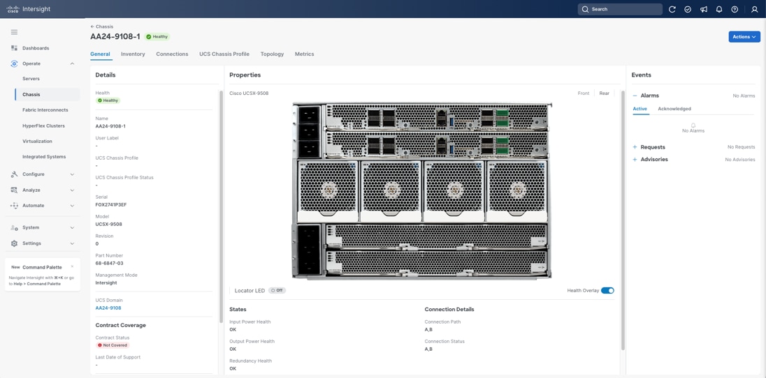
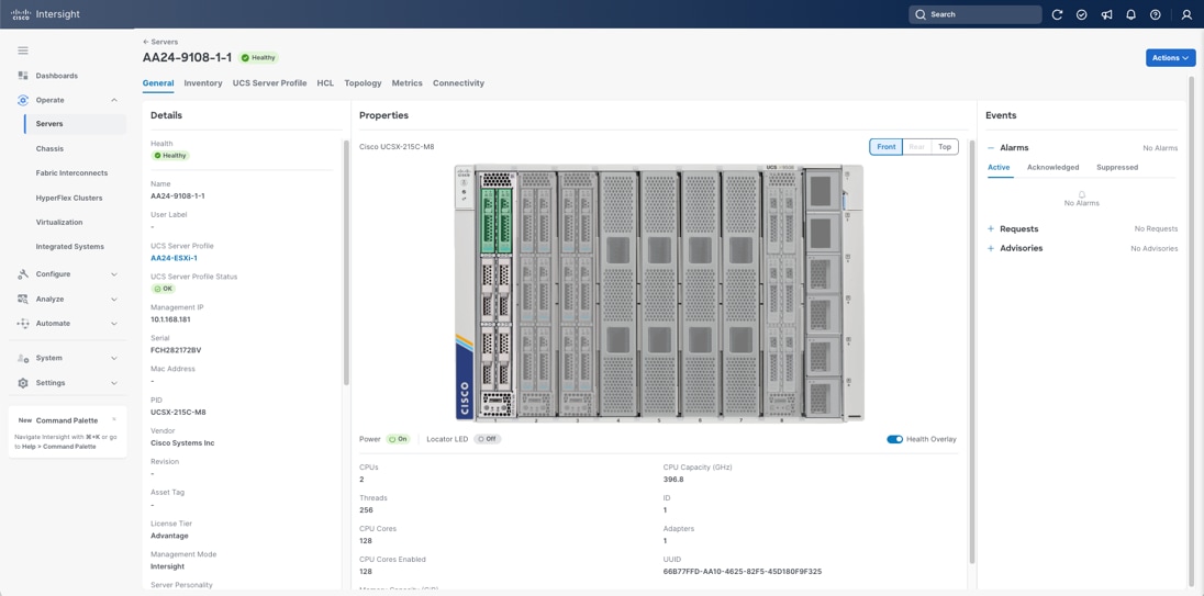
The Cisco UCS X9508 Chassis and Cisco UCS X215c M8 Compute Nodes are automatically discovered when the ports are successfully configured using the domain profile as shown in Figure 31, Figure 32, and Figure 33.
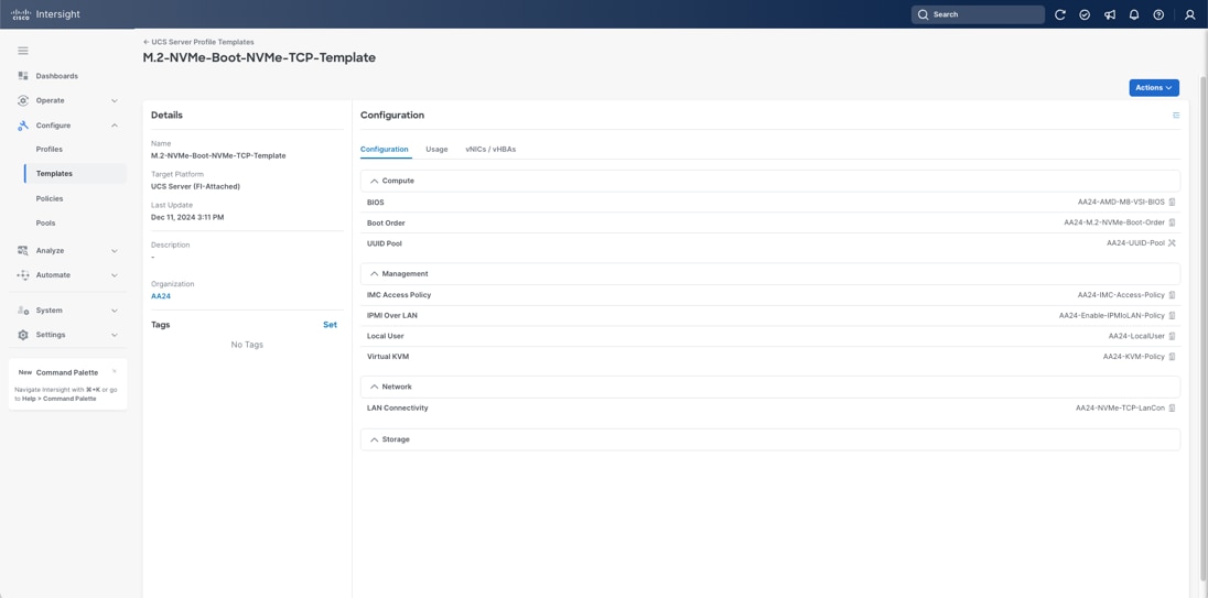
Server Profile Template
A server profile template enables resource management by simplifying policy alignment and server configuration. A server profile template is created using the server profile template wizard. The server profile template wizard groups the server policies into the following categories to provide a quick summary view of the policies that are attached to a profile:
● Compute policies: UUID pool, BIOS, boot order, and virtual media policies. (Firmware, Power, and Thermal polices are not used in this design)
● Management policies: Integrated Management Controller (IMC) Access, Intelligent Platform Management Interface (IPMI) over LAN, and virtual Keyboard, Video, and Mouse (KVM) policies. (Certificate Management, Local User, Serial over LAN (SOL), Simple Network Management Protocol (SNMP), and Syslog policies are not used in this design)
● Storage policies: Used to reference the local disk device that will be presented to the operating system. This includes the RAID or JBOD specification along with which disks in the system will be used.
● Network policies: adapter configuration, LAN connectivity, and SAN connectivity policies.
Note: The LAN connectivity policy requires you to create Ethernet network policy, Ethernet adapter policy, and Ethernet QoS policy.
Note: The SAN connectivity policy is not used in this design.
Some of the characteristics of the server profile template are as follows:
● BIOS policy is created to specify various server parameters in accordance with UCS VSI best practices and Cisco UCS Performance Tuning Guides.
● Boot order policy defines virtual media (KVM mapped DVD), the Local Disk defined by the Storage Policy, and a CIMC mapped DVD for OS installation.
● IMC access policy defines the management IP address pool for KVM access.
● LAN connectivity policy is used to create four virtual network interface cards (vNICs); two for management virtual switches (vSwitch0), two for application vSphere Distributed Switch (vDS), and two for the IPStorage (vDS) used for the NVMe over TCP traffic; along with various policies and pools.
Figure 34shows various policies associated with the server profile template.
Derive and Deploy Server Profiles from the Cisco Intersight Server Profile Template
The Cisco Intersight server profile allows server configurations to be deployed directly on the compute nodes based on polices defined in the server profile template. After a server profile template has been successfully created, server profiles can be derived from the template and associated with the Cisco UCS Compute Nodes, as shown in Figure 35.
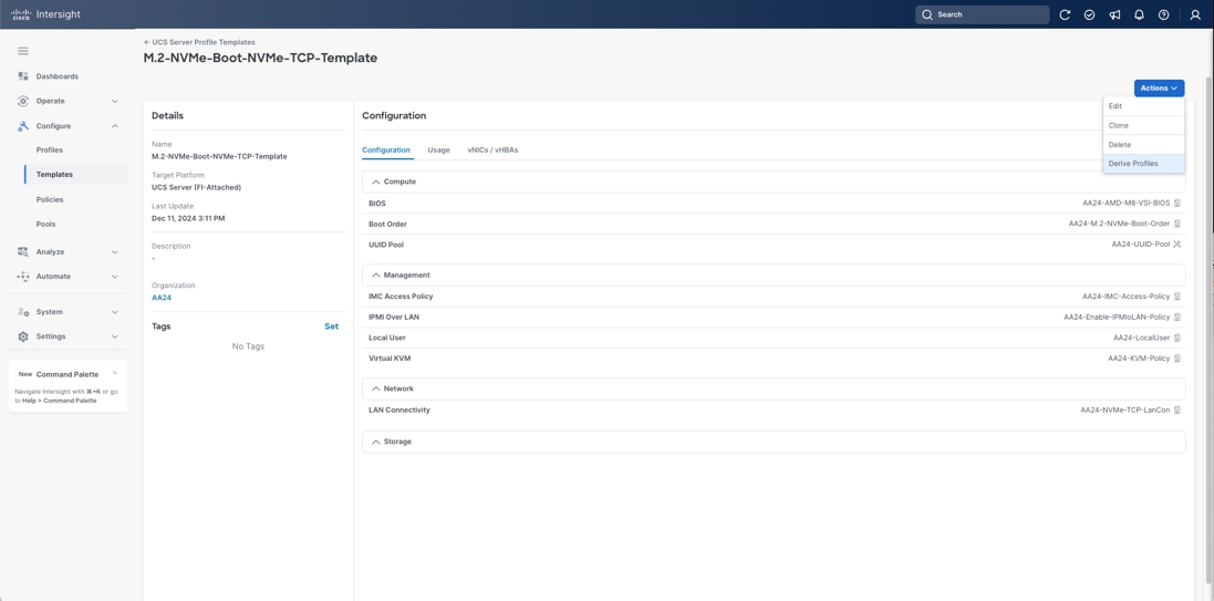
On successful deployment of the server profile, the Cisco UCS Compute Nodes are configured with parameters defined in the server profile.
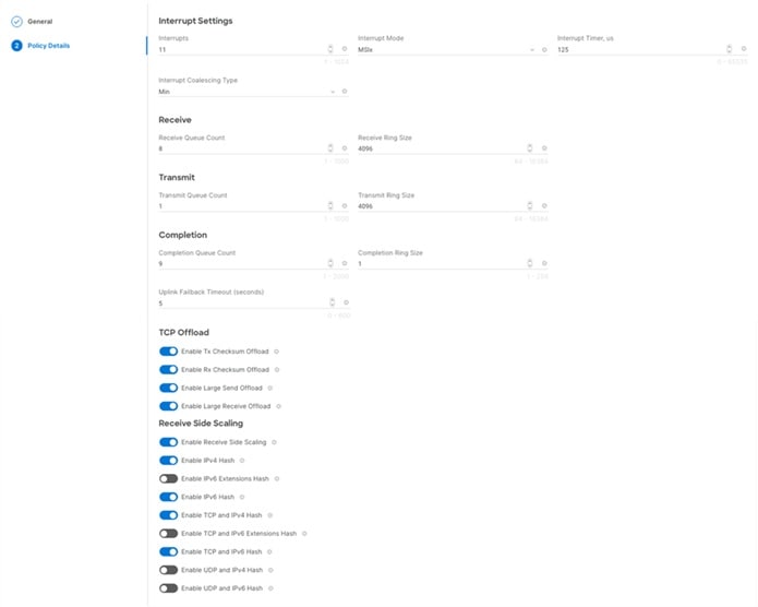
Cisco UCS Ethernet Adapter Policies
The processing of Ethernet packet can be adjusted within Cisco UCS to use of Cisco UCS Ethernet Adapter policies to optimize network traffic into multiple receive (RX) queues and maximize the use of multiple CPU cores in servicing these queues resulting in higher network throughput on up to 100Gbps interfaces. IMM (and UCSM) adapter policies allow the number of transmit (TX) and RX queues and the queue ring size (buffer size) to be adjusted, and features such as Receive Side Scaling (RSS) to be enabled. RSS allows multiple RX queues to each be assigned to a different CPU core, allowing parallel processing of incoming Ethernet traffic.
VMware ESXi 8.0 U3 supports RSS, a single TX queue, and up to 16 RX queues. This CVD utilizes the fifth-generation Cisco VICs which support a ring size up to 16K (16,384), where the previous fourth-generation VICs support a ring size up to 4K (4096). Increasing the ring size can result in increased latency, but with the higher speed 100Gbps interfaces used in this CVD, the data moves through the buffers in less time, minimizing the latency increase. In this CVD, two Ethernet Adapter policies are defined, with additional policies with higher ring sizes possible for environments incorporating IP based storage.
Table 2. Cisco UCS Ethernet Adapter Policy specifics
| Policy Name |
TX Queues |
TX Ring Size |
RX Queues |
RX Ring Size |
RSS |
| VMware-Default |
1 |
256 |
1 |
512 |
Disabled |
| VMware-HighTraffic |
1 |
4096 |
8 |
4096 |
Enabled |
Figure 36 shows part of the VMware-High-Trf Ethernet Adapter policy in Cisco Intersight. For more information on configuring Ethernet Adapter polices, see: https://www.cisco.com/c/en/us/products/collateral/interfaces-modules/unified-computing-system-adapters/ucs-vic-15000-series-ether-fabric-wp.html.
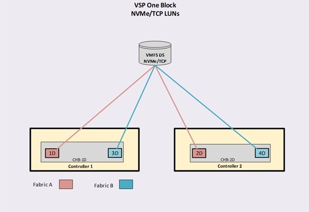
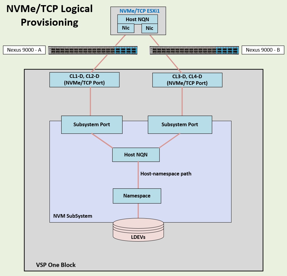
Each VSP One Block system includes two controllers and supports connectivity through a variety of storage protocols, depending on the selected Channel Host Bus Adapters (CHBs). Using multiple CHBs within the storage system allow the design of multiple layers of redundancy, enhancing availability and maintaining performance during failure events. In this architecture, the VSP One Block is configured with two NVMe/TCP CHBs installed across separate controllers. Each NVMe/TCP CHBs provides two individual 100 Gbps ports, allowing redundant connections to each fabric within the Cisco UCS infrastructure. In this deployment, a total of four ports are configured for NVMe/TCP protocol, two ports from Controller 1 and two ports from Controller 2.
NVMe/TCP ports CL1-D and CL2-D connect to the Cisco Nexus Ethernet fabric-A, whereas ports CL3-D and CL4-D connect to the Cisco Nexus Ethernet fabric-B.
With Cisco UCS providing alternate data paths, the Ethernet fabric delivers a total of four redundant paths per host to the VSP One array.
This CVD describes an NVMe/TCP storage deployment. When using the NVMe/TCP protocol on the storage array, local storage is used for server boot LUNs which must be configured on UCS server internal storage using M.2 drives.
Hitachi VSP One Block Administrator
VSP One Block Administrator is a configuration management application for the VSP One Block storage system that reduces storage management complexities, as it is built into the controller and requires no additional software deployment. VSP One Block Administrator includes a Command Control Interface (CCI) console, which provides Raidcom command-line configuration support for the NVMe/TCP storage subsystems. For this CVD, Hitachi VSP One Block Administrator and CCI were the primary methods used to configure the IP-based storage protocol settings on the array.
The Hitachi VSP One Block Administrator GUI was used to complete the following tasks for the NVMe/TCP storage protocol:
● Creating Dynamic Drive Protection (DDP) Storage Pools. DDP is an implementation where parity data is stored on the data drives instead of dedicated parity drives. VSP One Block supports dual-parity DDP groups (6D+2P, 14D+2P). Within this CVD, DDP Storage Pools were used to create VMFS datastores and optional boot LUNs to the VSI infrastructure.
● Managing IP settings for 100 Gbps NVMe/TCP ports. IP configuration and TCP protocol parameters must be set.
The Hitachi VSP One Block Administrator CCI Raidcom utility was used to complete the following tasks for NVMe/TCP:
● Creating an NVM subsystem using CCI Raidcom. NVMe/TCP requires creation of the NVM subsystem to manage paths between the host and a logical volume. This includes setting the host mode, and namespace security (enabled by default).
Note: The host mode “VMWARE_EX” should be used.
● Registering NVMe/TCP ports with the NVM subsystem using CCI Raidcom. This step adds the 100 Gbps storage ports to the NVM subsystem.
● Adding host NVMe Qualified Name (NQN) to the NVM subsystem using CCI Raidcom. This allows the host NQN to access the NVM subsystem.
● Creating LDEVs using CCI Raidcom.
● Creating an LDEV namespace using CCI Raidcom This registers the LDEV with the NVM Subsystem ID.
● Registering the host NQN to the Namespace ID. This allow access for the host by setting the host NQN-Namespace Path.
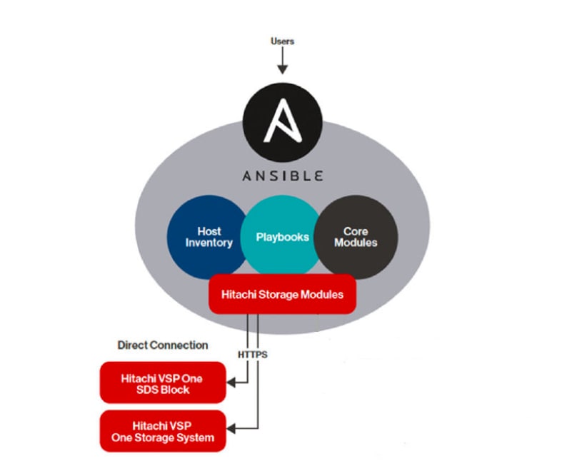
Hitachi VSP One Block Storage Modules for Red Hat Ansible
As part of this design implementation, users requiring automation capabilities can use the Hitachi VSP One Block Storage Modules to configure and manage the VSP One Block system. These Ansible modules provide administrators with a streamlined way to automate common storage tasks and integrate VSP One Block operations into broader IT automation workflows:
● General Storage Configuration
● Fibre Channel System Configuration
● NVMe-oF System Configuration
● iSCSI Configuration
● Local Replication
● Remote Replication
The following figure illustrates of the Hitachi Vantara VSP One Block Storage Modules for Red Hat Ansible.
Prerequisites
Operating systems that support the appropriate Ansible Core and Python modules must be used. For this design, RedHat Enterprise Linux (RHEL) 8.10 was deployed with Ansible core version 2.16.3 and Python 3.12.10.
For more information about the Hitachi VSP One Block Ansible Modules, see https://galaxy.ansible.com/ui/repo/published/hitachivantara/vspone_block/.
For more information about validated automation templates for this CVD, see: https://github.com/ucs-compute-solutions/Cisco_and_Hitachi_AdaptiveSolutions_IMM_X-Direct_VSP_One.
The VMware vSphere design incorporates concepts and best practices from VMware, Cisco, and Hitachi in setting up ESXi hosts on Cisco UCS servers to deliver reliability and performance of those servers to the Hitachi storage and Cisco Nexus network they connect to.
ESXi VIC Virtual Adapters
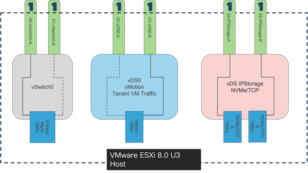
Multiple vNICs are created for the ESXi hosts using the Cisco Intersight server profile using the Cisco VIC 15230 adapters and are then assigned to specific virtual and distributed switches. The vNIC distribution for the ESXi hosts is as follows:
● Two vNICs (one on each fabric) for the VMware virtual switch vSwitch0 to support the in-band management traffic. The port group for the management traffic is pinned to UCS Fabric A to reduce the need to leave the fabric for management communication between the ESXi hosts. The standard VMware-Default Cisco UCS Ethernet adapter policy is assigned to these vNICs.
● Two vNICs (one on each fabric) for the VMware vSphere Distributed Switch (vDS) vDS0 to support customer data traffic and vMotion traffic. In this vDS, VMware vMotion is pinned to UCS Fabric B ensuring vMotion is switched in the B-side fabric interconnect for the same traffic concentrations reasons that keeps management traffic isolated to Cisco UCS Fabric A. The higher performance VMware-HighTraffic Cisco UCS Ethernet adapter policy configured within this design uses Receive Side Scaling (RSS) and is assigned to these vNICs.
● Two vNICs (one on each fabric) for over the IP Storage vDS to deliver the NVMe over TCP traffic from the Hitachi VSP One Block targets to the Cisco UCS X-Series initiators. The vNICs associated with this vDS are configured with a specific IPStorage Ethernet Adapter policy to have adjustment to the adapter Interrupts, Receive Queue Count, Receive Ring Size, and Transmit Ring Size to optimize this type of traffic.
● Within this validated VSI architecture, the vNICs are presented as 100G virtual connections presented from the VIC 15230.
Figure 39 shows the ESXi virtual adapter configurations in detail.
Cisco Hardware Support Manager (HSM) for VMware vCenter Integration with Cisco Intersight
The Cisco Hardware Support Manager (HSM) is enabled by the connection from the VMware vCenter through the Cisco Intersight Assist to be used within vSphere Lifecycle Manager (vLCM). This provides the ability to update the operating system drivers (VIBs) and perform firmware upgrades simultaneously with a single firmware image allowing for image consistency at a cluster level.
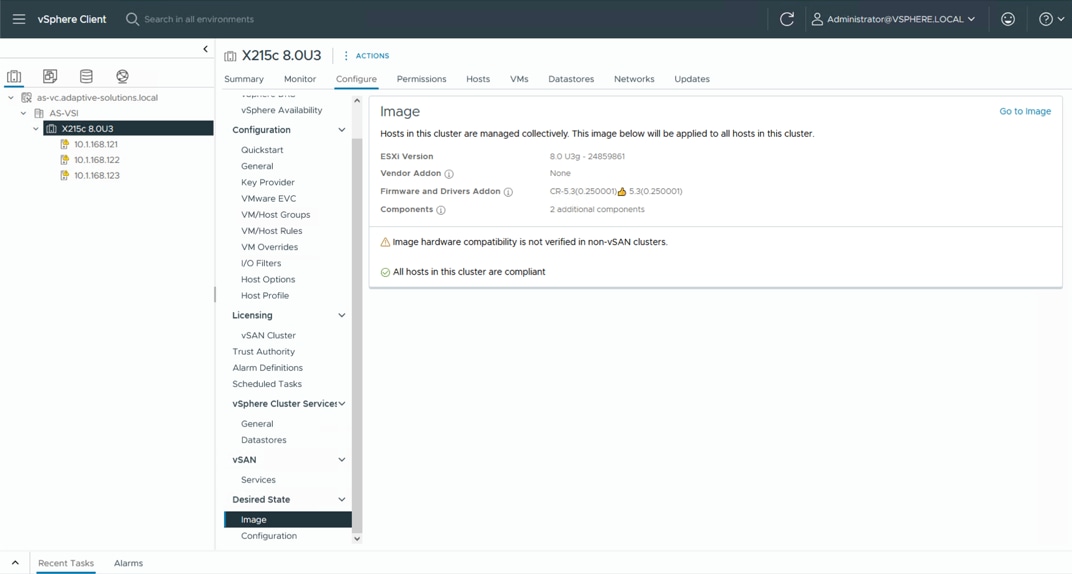
The Cisco Intersight HSM becomes available within vLCM after the VMware vCenter is added as a target within Cisco Intersight from Cisco Intersight Assist providing firmware and driver as updates for the cluster.
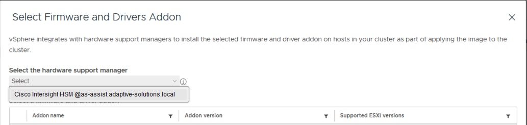
Cluster compliance with the image is tracked, and individual hosts can be updated within vLCM and automatically rebooted to bring them into compliance.
Cisco Intersight Integration with VMware vCenter, Hitachi Storage, and Cisco Switches
Hitachi storage and VMware vCenter connect to Cisco Intersight using third-party device connectors, and Cisco Nexus and MDS switches using a Cisco device connector. Cisco Intersight Assist virtual appliance enables Cisco Intersight to communicate with both non-Cisco devices and supported Cisco switches because third-party infrastructure does not contain any built-in Cisco Intersight device connector. Cisco Intersight uses:
● The device connector running within the Cisco Intersight Assist virtual appliance to communicate with the VMware vCenter.
● The device connector running within a Cisco Intersight Assist virtual appliance to connect with the Hitachi VSP One Block.
● The device connector running within the Cisco Intersight Assist virtual appliance to communicate with Cisco Nexus 9000 and MDS switches.
Note: A single Cisco Intersight Assist virtual appliance can support Hitachi VSP storage, VMware vCenter, and Cisco switches.
Note: MDS is mentioned for the feature support within Intersight, but MDS is not utilized in this design.
Cisco Intersight integration with VMware vCenter, Hitachi VSP, and Cisco switches enables customers to perform the following tasks right from the Cisco Intersight dashboard:
● Monitor the virtualization, storage, and switching environment.
● Add various dashboard widgets to obtain useful at-a-glance information.
● Perform common Virtual Machine tasks such as power on/off, remote console and so on.
● Orchestrate virtual, storage, switching, environment to perform common configuration tasks.
The Adaptive Solutions architecture enables customers to use new management capabilities with no compromise in their existing Hitachi VSP, VMware, and switch operations. IT users will be able to manage heterogeneous infrastructure from a centralized Cisco Intersight portal. At the same time, the IT staff can continue to use Hitachi VSP, VMware vCenter, and Cisco Switch Interfaces for comprehensive analysis, diagnostics, and reporting of virtual, storage, and switching environments. For more information about the ICO capabilities with Hitachi VPS, go to the best practices guide: https://docs.hitachivantara.com/v/u/en-us/application-optimized-solutions/mk-sl-280
Additionally, you can refer to the following GitHub repository for additional ICO automation templates that were created and validated for this CVD: https://github.com/ucs-compute-solutions/Cisco_and_Hitachi_AdaptiveSolutions_IMM_X-Direct_VSP_One
Obtain Storage-level Information
With the Cisco Intersight Assist deployed and connected to the Intersight SaaS platform, the Hitachi VSP can be brought into visibility from a connection with Cisco Intersight Assist.
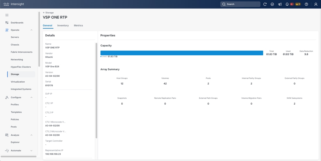
Obtain VMware vCenter and Cisco Switch Information
After successfully claiming the VMware vCenter and supported Cisco switches as targets, customers can also view information on these products in Cisco Intersight.
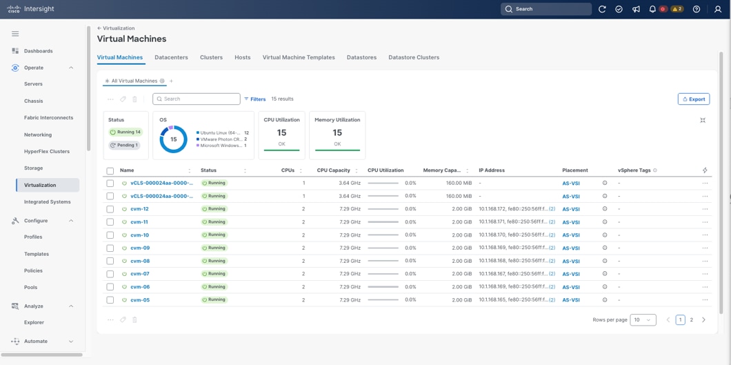
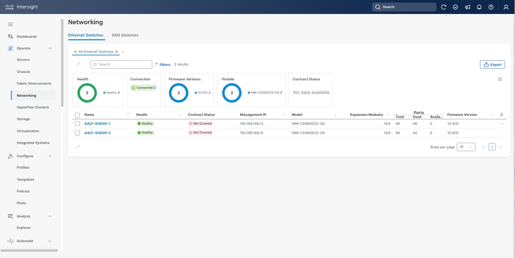
Detailed views of the VMware vSphere subcomponents and the added switches are available by selecting the left-side menu options and listed targets.
All components in the Adaptive Solutions design are built to create a secure infrastructure, accessible only by those who need it within their operational categories.
Cisco Intersight
Cisco Intersight supports SSO (Single-Sign-On), along with RBAC controls to structure access and permissions to managed resources. With Cisco UCS overseen by Intersight Managed Mode, all servers become centrally maintained by consistent access policies which are secured by default:
● SSH (TCP port 22) – Encrypted and enabled by default (it cannot be disabled)
● HTTPS (TCP port 443) – Encrypted (OpenSSL-based)
● KVM Management (TCP port 2068) – Encrypted (RC4)
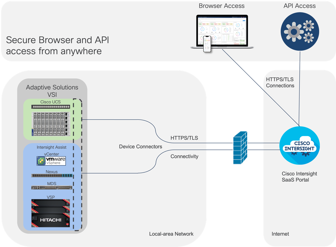
Within the Cisco UCS platform, the Cisco UCS X-Series servers also support an optional Trusted Platform Module (TPM) and UEFI Secure Boot. Additional security features include a secure boot FPGA and ACT2 anticounterfeit provisions.
In this design, operational components are separated by in-band and out-of-band networks to insulate traffic as needed. Zoning within VSANs restricts FC traffic to designated targets and initiators as a base level of isolation. Cisco Nexus supports RBAC, TACACS+, RADIUS and direct LDAP, for structuring permissions and ensuring secure access. Information on further securing Cisco Nexus switches can be found here: https://sec.cloudapps.cisco.com/security/center/resources/securing_nx_os.html
Hitachi VSP Security
The Hitachi VSP series includes multiple security features designed to protect sensitive data, prevent unauthorized access, and meet stringent compliance requirements, which include:
● Protection from unauthorized access: All VSP series models are hardened to prevent data leaks and unauthorized system access. These measures help safeguard sensitive data, meet stringent data privacy requirements, and adhere to strict regulatory compliance policies. Additional measures are available to ensure quick recovery from ransomware attacks.
● Data Security for VSP Storage System: Hitachi storage systems provide the following capabilities to ensure data confidentiality and integrity:
◦ Data Retention Utility: Protects data volumes from read and/or write operations by defining retention terms for designated volumes.
◦ Volume Shredder: Erases data at the end of the retention period by overwriting it with dummy data, preventing recovery of deleted information.
◦ Data-at-Rest Encryption (DARE): Provides hardware-based Advanced Encryption Standard (AES) encryption through Encryption License Keys, which enables you to implement and manage data-at-rest encryption for sensitive data on your storage system.
The data-at-rest encryption functionality is implemented using cryptographic hardware (chips) on the encrypting controllers (ECTLs) of the VSP One Block Storage system. The ECTLs encrypt and decrypt data as it is being written to and read from the cached memory.
Encryption Management: Encryption is enabled or disabled at the Dynamic Disk Pool (DDP) group level. All drives within a DDP group (parity group) are either encrypting or non-encrypting.
Although it is possible to configure both encrypting and non-encrypting DDP groups on the ECTL, best practice is to enable encryption for all DDP groups.
Configuration and deployment of encryption should align with business and security requirements.
For more information about encryption system requirements, configuration details, key management, backup, rotation, restoration and Key Management Server (KMS) deployment, see: https://docs.hitachivantara.com/r/en-us/svos/10.4.x/mk-23vsp1b010
Note: The creation and secure storage of encryption backup keys must be part of the organization’s corporate security policy. To ensure data availability, keys should be backed up immediately after creation and again after any hardware maintenance involving drive or ECTL replacement. Users are responsible for securely storing secondary backup keys.
VMware vSphere
VMware vSphere 8.0 U3 brings improvements including the support of TLS 1.3 and 1.2 within TLS profiles, PingFederate Identity Provider for vSphere and numerous vulnerability fixes.
VMware vCenter supports SSO, configurable to an Active Directory server allowing RBAC for differentiated access levels and centralized account management. Firewall settings for hosts, access using SSH and lockdown mode can be set consistently at the cluster level using configuration profiles. Prompt remediation of security updates can also be easily managed through VMware vSphere Lifecycle Manager.
More information on VMware vSphere security best practices can be found here: https://core.vmware.com/vmware-vsphere-8-security-configuration-guide
Data centers around the world currently account for 1 percent of the global electricity consumption, with this percentage doubling for total amount consumed within US, making them a considerable factor to energy consumption. Among the various components within a data center, servers are identified to consume the largest share of the electricity. According to Gartner, the proportion of the overall data center power budget allocated to storage is expected to double by 2030, rising from less than 20 percent in 2020 to nearly 40 percent.
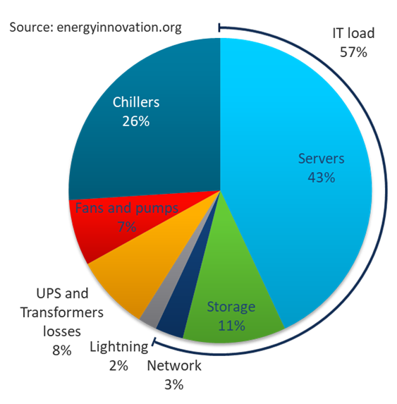
Reducing datacenter power consumption is an important goal, and the Adaptive Solutions design offers several implementations and options to address sustainability, some of which are detailed below.
Sustainable Design
One key approach is to focus on a modern, sustainable design while striving to increase overall efficiency. Data center consolidation, modernization and maximizing rack utilization are crucial steps to achieve this goal.
Replacing older servers with advanced models, such as the Cisco UCS M8 servers introduced in this solution can significantly improve performance and achieve higher virtual machine (VM) consolidation ratios compared to previous generations, while continuing to provide more flexibility and increased performance to support new and evolving applications.
The Cisco UCS X-9508 used in this solution provides a future-ready platform with the density and efficiency of blade servers and the expandability and flexibility of rack servers. The modular, chassis-based design allows you to share resources (chassis enclosure, switching fabric, power, and cooling) among multiple servers for a more efficient utilization of rack space, power, and cooling, while maintaining the flexibility to expand capabilities as needed. The Cisco UCS-X9508 7-RU chassis supports up to 8 compute nodes with unified connectivity and management. Each compute node can also support up to 6 Solid-State Drives (SSDs), or Non-Volatile Memory Express (NVMe) drives for a total of ~90TB of local storage using 15.3TB NVMe drives available today. For AI/ML, VDI and other compute-intensive workloads, you can add NVIDIA and Intel Flex GPUs to the Cisco UCS X-Series chassis, directly on each compute node or using a dedicated PCIe (X440p) node. Cisco UCS-X9508 can support up to 16 GPUs using the X440p PCIe nodes, with the option to add an additional two GPUs on the compute nodes. Cisco UCS X-Series is also designed for the next decade of computing, with the ability to support new technologies as they evolve and mature such as PCI Gen5.0, CXL and liquid cooling for a more efficient data center.
Sustainable Components
Hitachi Virtual Storage Platform and Cisco UCS X-Series platform used in this solution are committed to sustainability in their design and implementation of both products. These are critical tools for enterprises as they modernize their data centers and select infrastructure to consolidate their workloads.
Cisco UCS X-Series Platform Sustainability
The Cisco UCS X-Series platform is designed with several energy efficient features to optimize power and cooling as outlined below.
● Cisco UCS X-Series chassis uses a more open design for less air impedance and minimal air-handling material to reduce the overall resources that need to be sourced and installed within the system.
● It is equipped with modular, titanium-rated power supply units (PSUs) and 54-volt DC-power delivery system that minimizes the many internal power conversions, internal copper cabling needed, and amperage – saving in both overhead and power loss.
● The Cisco UCS X-Series has modular counter-rotating fans with wider apertures and high cubic feet per minute (CFM). It also has innovative zone-based cooling to optimize only those components needing more handling. With an innovative fan speed algorithm, an industry first, the Cisco UCS X-Series can optimize power consumption and minimize hysteresis to prevent fan speed overshot and reduce overall fan power consumption.
● The architecture of the Cisco UCS X-Series can extend the useful life of server elements using a mid-plane-less design to disaggregate components, with the ability to support new high-speed interconnects in the future and extend the refresh cycle of components.
For Cisco UCS X-Series servers, server power usage is displayed under the server’s Statistics tab for various customizable intervals as shown below. By enabling Intelligent Platform Management Interface (IPMI) over LAN policy on each server, power usage and other metrics can be queried from IPMI over LAN, allowing multiple management components (for example, VMware vCenter and Cisco Intersight) to monitor and provide a broader picture of the power consumption over time from a server and workload perspective. Alternatively, you can also use Redfish to query server power usage when managing the servers in Intersight Managed Mode.
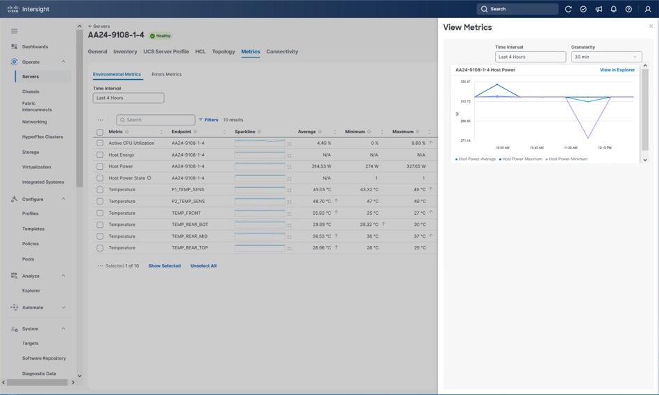
To reduce power consumption, Cisco Intersight provides Server BIOS policies that can be configured to potentially conserve power without affecting performance. These policies provide multiple options specifying both how Cisco UCS X-Series Chassis fans are controlled and how Cisco UCS X-Series Chassis power supplies are used. Additionally these policies provide priority levels for Cisco UCS X-Series servers for power allocation to these servers.
Note: For more information on the BIOS policy options and recommendations, see Performance Tuning for Cisco UCS M8 Platforms with AMD EPYC 4th and 5th Gen Processors.
The Cisco UCS Chassis can also implement a policy through Cisco Intersight to provide intelligent options in power use. These options are:
● Power Redundancy: Redundancy Mode determines the number of PSUs the chassis keeps as redundant. N+2 mode is only supported on Cisco UCS X-Series.
● Power Save Mode: If the requested power budget is less than available power capacity, the additional PSUs not required to comply with redundancy policy are placed in Power Save mode.
● Dynamic Power Rebalancing: If enabled, this mode allows the chassis to dynamically reallocate the power between servers depending on their power usage.
● Extended Power Capacity: If enabled, this mode allows chassis available power to be increased by borrowing power from redundant power supplies.
● Power Allocation (Watts): Sets the Allocated Power Budget of the Chassis. This field is only supported for Cisco UCS X-Series Chassis.
VMware vSphere Sustainability
VMware vSphere used in the Adaptive Solutions design also provides several energy management capabilities as outlined below:
● Host Power Management (HPM) – When a host is powered on, this feature can reduce the power consumption of the host. This is enabled using the Power Policy option that can be set to High Performance, Balanced, Low Power, or Custom and interacts with the server BIOS settings. In this CVD, the policy is set to Balanced (default) for a balance between power consumption and performance. Enterprises can change this policy as needed to meet the needs of their workloads and environment. In VMware vSphere 8.0, this policy can be changed by navigating to <vSphere Cluster Name> > Host > Configure > Hardware > Overview.
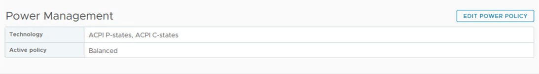
Note: The technology field shows a list of the technologies available to ESXi on that host and is derived from the server BIOS settings. For power savings, both ACPI P-states and ACPI C-states should be available to ESXi.
For more details on the options, see Performance Best Practices for VMware vSphere 8.0.
● Distributed Power Management (DPM) – Unlike HPM, DPM reduces power consumption by powering-off underutilized ESXi hosts in a cluster. DPM will first migrate virtual machines to other hosts in the cluster before putting the hosts into stand-by. When demand increases, DPM will bring the hosts back online and load-balance workloads across all hosts in the cluster. DPM uses Distributed Resource Scheduling (DRS) to migrate VM workloads and is therefore configured along with DRS (at the cluster-level) as shown below from navigating to <vSphere Cluster Name> > Configure > Services > vSphere DRS, select EDIT… and find the DPM configuration within the Power Management tab.
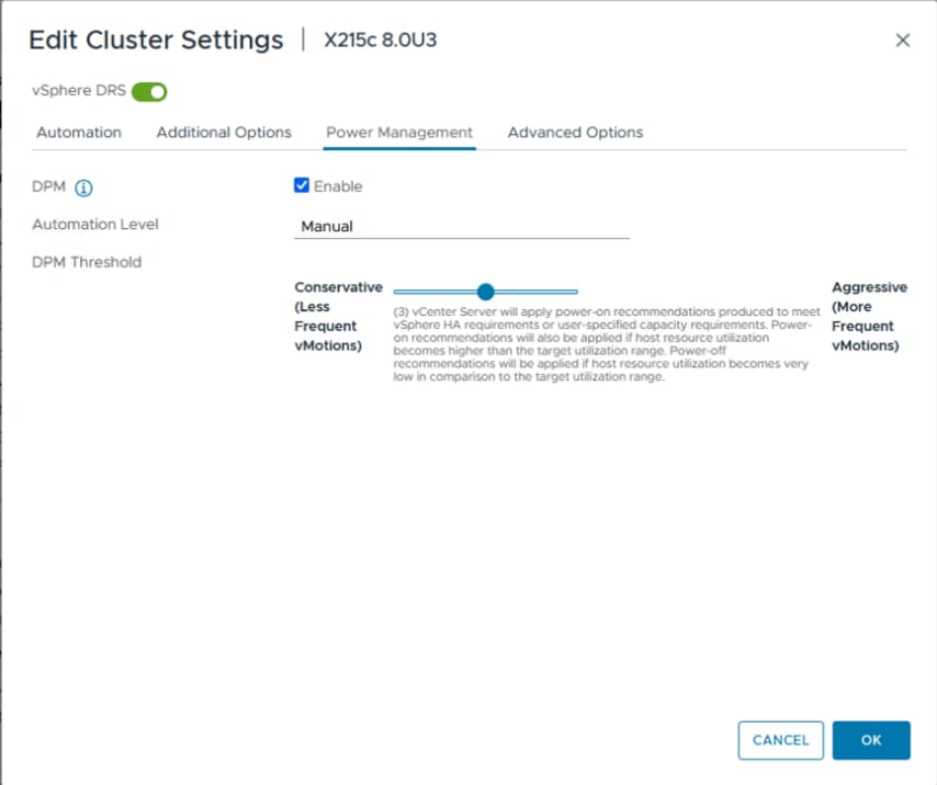
Note: DPM does not violate VMware High Availability (HA) settings and takes it into account to meet the HA requirements.
Note: DPM requires IPMI configuration on the UCS server that was deployed using the IPMI over LAN policy in the UCS Server Profile configuration as discussed earlier. IPMI settings must also be configured on each ESXi host in VMware vCenter by navigating to <vSphere Cluster Name> > Host > Configure > System > Power Management as shown below. In this setup, IPMI over LAN is used to power on a suspended server when demand on the cluster increases.
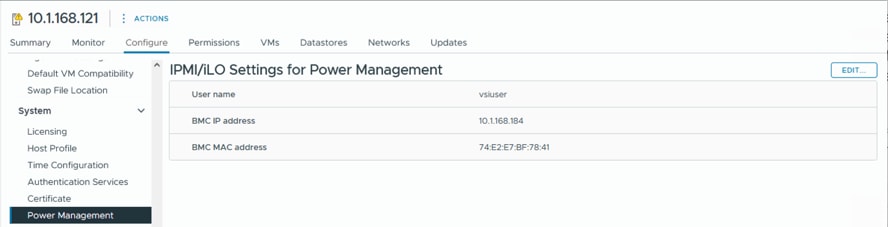
Note: DPM currently does not work with Cisco UCS C-Series servers in Intersight Managed Mode.
● Displaying VMware ESXi Host Power Usage – In addition to IPMI over LAN, local IPMI is also supported in VMware ESXi with Cisco UCS servers. VMware ESXi can use local IPMI to query many server hardware sensors, including server power usage as shown below by navigating to <vSphere Cluster Name> > Host > Monitor > Hardware Health.
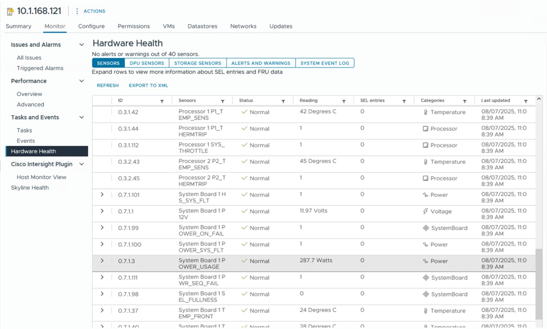
Hitachi VSP Sustainability
The Hitachi VSP storage solution is certified with Carbon Footprint of Products (CFP), a scheme that “visualizes” CO2 equivalent emissions by converting greenhouse gas emissions across all life cycle stages of a product from raw material acquisition through disposal and recycling.
Hitachi’s eco-friendly storage systems are designed to reduce environments impact, achieving an estimated 30 percent to 60 percent reduction in CO2 emissions compared to previous models.
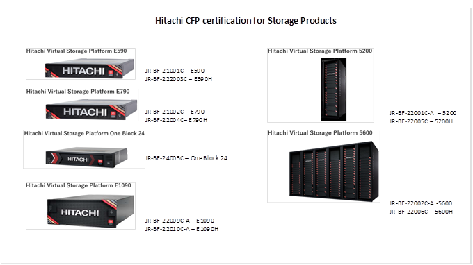
For more information, see: Hitachi Information and Communications Environmental Initiatives SuMPO EPD
In addition, the Hitachi Virtual Storage Platform (VSP) delivers the following benefits for building a greener datacenter:
● Unique hardware-based data compression reduces power consumption by approximately percent
● Accelerated compression processing improves read/write performance by up to 40 percent
● Automatic switching optimizes performance while enabling energy savings
● Elimination of data migration requirements minimizes waste and further reduces energy usage
The Hitachi VSP One Block storage solution is also certified under the U.S. ENERGY STAR® program and is ranked number one in its class.
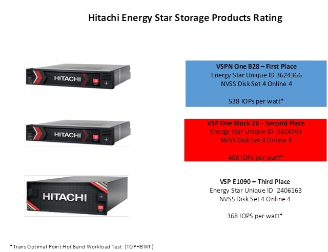
For a VSP B24 system, which was used in the validation of this CVD, energy star certification can be referenced here: ENERGY STAR Certified Data Center Storage
Some of the key design considerations for the Adaptive Solutions VSI architecture are explained in this section.
Management Design Considerations
Out-of-band Management Network
The management interface of every physical device is connected to a dedicated out-of-band management switch which can be part of the existing management infrastructure in a customer’s environment. The out of band management network provides management access to all the devices in the environment for initial and on-going configuration changes. The routing and switching configuration for this network is independent of the deployment and therefore changes in configurations do not impact management access to the devices. In this CVD, the out-of-band management network is carried within the Cisco Nexus uplinks to allow Cisco UCS CIMC/KVM connectivity.
In-band Management Network
The in-band management is a VLAN configured for connectivity to internally accessed infrastructure in the design. The primary example for in-band connectivity is the management connectivity for VMware vCenter, ESXi and other management components like Hitachi VSP 360. The hardware management interfaces to the Nexus, MDS, UCS, and the Hitachi VSP are in the out-of-band management network which has direct Layer 3 access to the in-band management network. In a production environment might require a firewall separating the two.
VMware vCenter Deployment Consideration
While hosting the VMware vCenter on the same ESXi hosts that the vCenter is managing is supported, it is a best practice to deploy the VMware vCenter on a separate management infrastructure which was the approach in this design. The in-band management VLAN provides connectivity between the VMware vCenter and the ESXi hosts deployed in the environment. In this CVD Deployment Guide, the steps for installing VMware vCenter are not covered, but the configuration is started from what would be considered a fresh install of the VMware vCenter appliance.
Jumbo Frames
An MTU of 9216 is configured at all network levels to allow jumbo frames as needed by the guest OS and application layer. This allows the network at every point to negotiate an MTU up to 9000 with the end point. For VLANs that leave through the Nexus switch uplinks (IB-MGMT and VM-Traffic networks), all endpoints should have an MTU of 1500. For Storage and vMotion VLANs that stay within the design, an MTU of 9000 should be used on all endpoints for higher performance. It is important that all endpoints within a VLAN have the same MTU setting. It is important to remember that most virtual machine network interfaces have an MTU of 1500 set by default and that it may be difficult to change this setting to 9000, especially on many virtual machines. Note that a VLAN tagged trunk can contain both VLANs with MTU 1500 and VLANs with MTU 9000 interfaces.
NTP
For many reasons, including authentication and log correlation, it is critical that all components are properly synchronized to a time-of-day clock. To support this synchronization, all components in this design support network time protocol (NTP). In the setup, the two Cisco Nexus switches are synchronized through NTP to at least two external NTP sources. Cisco Nexus NTP distribution is then set up and all the other components can use the IP of any of the switches’ L3 interfaces, including mgmt0 as an NTP source. If a customer already has NTP distribution in place, that can be used instead of Cisco Nexus switch NTP distribution.
UEFI Secure Boot
This validation uses Unified Extensible Firmware Interface (UEFI) Secure Boot. UEFI is a specification that defines a software interface between an operating system and platform firmware. With UEFI secure boot enabled, all executables, such as boot loaders and adapter drivers, are authenticated as properly signed by the BIOS before they can be loaded. Additionally, a Trusted Platform Module (TPM) is also installed in the Cisco UCS compute nodes. VMware ESXi 8.0 U3 supports UEFI Secure Boot and VMware vCenter 8.0 U3 supports UEFI Secure Boot Attestation between the TPM module and ESXi, validating that UEFI Secure Boot has properly taken place.
NVMe/TCP
This validation supports NVMe over TCP (NVMe/TCP) to provide the high-performance and low-latency benefits of NVMe across fabrics connecting servers and storage. NVMe/TCP is implemented through the NVMe/TCP standard which is designed to enable NVMe based message commands to transfer data and status information between a host computer and a target storage subsystem via an Ethernet network fabric.
Deployment Hardware and Software
This chapter contains the following:
● Hardware and Software Revisions
Hardware and Software Revisions
Table 3 lists the hardware and software used in this solution.
Table 3. Hardware and Software Revisions
| Component |
Software |
|
| Network |
Cisco Nexus 93600CD-GX |
10.4(5)M |
| Compute |
Cisco UCS X-Series Direct Fabric Interconnect |
4.3(5.250033) |
| Cisco UCS X215c with Cisco UCS VIC 15230 |
5.3(0.250001) |
|
| Cisco UCS Tools |
1.4.3 |
|
| Cisco VIC nenic Driver for ESXi |
2.0.15.0 |
|
| VMware ESXi |
Cisco Custom 8.0 U3g |
|
| VMware vCenter Appliance |
8.0 U3e |
|
| Cisco Intersight Assist Virtual Appliance |
1.1.2-0 (automatically upgrades to current release) |
|
| Storage |
Hitachi VSP One Block |
SVOS 10.4.0 Code Version A3-04-02-40/00 |
| Ansible |
Hitachi Vantara VSP One Block Storage Modules for Red Hat Ansible |
VSP One Block Storage Modules: Version 3.5 Operating System: Red Hat Enterprise Linux (RHEL) 8.10 Automation Framework: Ansible-Core 2.16.3 Python Runtime: Python 3.12.8 |
About the authors
Ramesh Isaac, Technical Marketing Engineer, Cisco Systems, Inc.
Ramesh Isaac is a Technical Marketing Engineer in the Cisco UCS Data Center Solutions Group. Ramesh has worked in the data center and mixed-use lab settings for over 25 years. He started in information technology supporting UNIX environments and focused on designing and implementing multi-tenant virtualization solutions in Cisco labs before entering Technical Marketing where he has supported converged infrastructure and virtual services as part of solution offerings as Cisco. Ramesh has held certifications from Cisco, VMware, and Red Hat.
Gilberto Pena Jr, Virtualization Solutions Architect, Hitachi Vantara
Gilberto Pena Jr. is a Virtualization Solutions Architect in the Infrastructure Platform Solutions Engineering group at Hitachi Vantara. He brings over 25 years of experience working with enterprise financial customers, with a focus on LAN and WAN design, as well as converged and hyperconverged virtualization solutions. He has also held certifications from Cisco.
Acknowledgements
The authors would like to thank the following individuals for their support and contributions to the design, validation, and creation of this Cisco Validated Design:
● John George, Technical Marketing Engineer, Cisco Systems, Inc.
● Christopher Dudkiewicz, Engineering Product Manager, Cisco Systems, Inc.
● Arvin Jami, Product Owner - Solutions Architect, Hitachi Vantara
● Sreeram Vankadari, Product Management, Hitachi Vantara
Appendix
This appendix contains the following:
● Compute
● Network
● Storage
Cisco Intersight: https://www.intersight.com
Cisco Intersight Managed Mode: https://www.cisco.com/c/en/us/td/docs/unified_computing/Intersight/b_Intersight_Managed_Mode_Configuration_Guide.html
Cisco Unified Computing System: https://www.cisco.com/site/us/en/products/computing/servers-unified-computing-systems/index.html
Cisco UCS X-Series Direct Fabric Interconnects: https://www.cisco.com/c/en/us/products/collateral/servers-unified-computing/ucs-x-series-modular-system/ucs-x-series-direct-ds.html
Cisco Nexus 9000 Series Switches: http://www.cisco.com/c/en/us/products/switches/nexus-9000-series-switches/index.html
Hitachi Virtual Storage Platform One Block: https://www.hitachivantara.com/en-us/products/storage-platforms/block-storage/midrange/vsp-one-block
Hitachi SVOS: https://www.hitachivantara.com/en-us/products/storage-platforms/primary-block-storage/virtualization-operating-system.html
VMware vSphere: https://www.vmware.com/products/cloud-infrastructure/vsphere
Cisco UCS Hardware Compatibility Matrix: https://ucshcltool.cloudapps.cisco.com/public/
VMware: https://compatibilityguide.broadcom.com/
Hitachi Product Compatibility Guide: https://compatibility.hitachivantara.com/
Feedback
For comments and suggestions about this guide and related guides, join the discussion on Cisco Community here: https://cs.co/en-cvds.
CVD Program
"DESIGNS") IN THIS MANUAL ARE PRESENTED "AS IS," WITH ALL FAULTS. CISCO AND ITS SUPPLIERS DISCLAIM ALL WARRANTIES, INCLUDING, WITHOUT LIMITATION, THE WARRANTY OF MERCHANTABILITY, FITNESS FOR A PARTICULAR PURPOSE AND NONINFRINGEMENT OR ARISING FROM A COURSE OF DEALING, USAGE, OR TRADE PRACTICE. IN NO EVENT SHALL CISCO OR ITS SUPPLIERS BE LIABLE FOR ANY INDIRECT, SPECIAL, CONSEQUENTIAL, OR INCIDENTAL DAMAGES, INCLUDING, WITHOUT LIMITATION, LOST PROFITS OR LOSS OR DAMAGE TO DATA ARISING OUT OF THE USE OR INABILITY TO USE THE DESIGNS, EVEN IF CISCO OR ITS SUPPLIERS HAVE BEEN ADVISED OF THE POSSIBILITY OF SUCH DAMAGES.
THE DESIGNS ARE SUBJECT TO CHANGE WITHOUT NOTICE. USERS ARE SOLELY RESPONSIBLE FOR THEIR APPLICATION OF THE DESIGNS. THE DESIGNS DO NOT CONSTITUTE THE TECHNICAL OR OTHER PROFESSIONAL ADVICE OF CISCO, ITS SUPPLIERS OR PARTNERS. USERS SHOULD CONSULT THEIR OWN TECHNICAL ADVISORS BEFORE IMPLEMENTING THE DESIGNS. RESULTS MAY VARY DEPENDING ON FACTORS NOT TESTED BY CISCO.
CCDE, CCENT, Cisco Eos, Cisco Lumin, Cisco Nexus, Cisco StadiumVision, Cisco TelePresence, Cisco WebEx, the Cisco logo, DCE, and Welcome to the Human Network are trademarks; Changing the Way We Work, Live, Play, and Learn and Cisco Store are service marks; and Access Registrar, Aironet, AsyncOS, Bringing the Meeting To You, Catalyst, CCDA, CCDP, CCIE, CCIP, CCNA, CCNP, CCSP, CCVP, Cisco, the Cisco Certified Internetwork Expert logo, Cisco IOS, Cisco Press, Cisco Systems, Cisco Systems Capital, the Cisco Systems logo, Cisco Unified Computing System (Cisco UCS), Cisco UCS B-Series Blade Servers, Cisco UCS C-Series Rack Servers, Cisco UCS S-Series Storage Servers, Cisco UCS X-Series, Cisco UCS Manager, Cisco UCS Management Software, Cisco Unified Fabric, Cisco Application Centric Infrastructure, Cisco Nexus 9000 Series, Cisco Nexus 7000 Series. Cisco Prime Data Center Network Manager, Cisco NX-OS Software, Cisco MDS Series, Cisco Unity, Collaboration Without Limitation, EtherFast, EtherSwitch, Event Center, Fast Step, Follow Me Browsing, FormShare, GigaDrive, HomeLink, Internet Quotient, IOS, iPhone, iQuick Study, LightStream, Linksys, MediaTone, MeetingPlace, MeetingPlace Chime Sound, MGX, Networkers, Networking Academy, Network Registrar, PCNow, PIX, PowerPanels, ProConnect, ScriptShare, SenderBase, SMARTnet, Spectrum Expert, StackWise, The Fastest Way to Increase Your Internet Quotient, TransPath, WebEx, and the WebEx logo are registered trade-marks of Cisco Systems, Inc. and/or its affiliates in the United States and certain other countries. (LDW_P1)
All other trademarks mentioned in this document or website are the property of their respective owners. The use of the word partner does not imply a partnership relationship between Cisco and any other company. (0809R)