Overview
The Cisco Nexus 93600CD-GX switch (N9K-C93600CD-GX) is a 1-rack unit (RU), fixed-port switch designed for deployment in data centers.
This switch has these ports:
-
28 10/40/100-Gigabit QSFP28 ports (ports 1-28)
-
8 10/40/100/400-Gigabit QSFP-DD ports (ports 29-36)
-
Two management ports (one 10/100/1000BASE-T port and one 1-Gbps SFP port)
-
One console port (RS-232)
-
1 USB port
 Note |
|
Supported mixed speed combination examples
Note |
In breakout mode, the speed of the 4 ports must be the same, either all 10G or all 25G. |
|
Port number |
Supported combinations |
|||
|---|---|---|---|---|
|
Port 1 |
4x10G |
Native 10G |
4x25G |
Native 25G |
|
Port 2 |
hw-disabled |
Native 10G |
hw-disabled |
Native 25G |
|
Port 3 |
Native 10G |
Native 25G |
4x25G |
4x25G |
|
Port 4 |
Native 10G |
Native 25G |
hw-disabled |
hw-disabled |
|
Port number |
Supported combinations |
|||
|---|---|---|---|---|
|
Port 1 |
4x10G or 4x25G |
Native 40/100G will be hw-disabled |
||
|
Port 2 |
hw-disabled |
Native 40/100G will be hw-disabled |
||
|
Port 3 |
Native 40/100G will be hw-disabled |
4x10G or 4x25G |
||
|
Port 4 |
Native 40/100G will be hw-disabled |
hw-disabled |
||
This switch includes these user-replaceable components:
-
Fan modules (six) with these airflow choices:
-
Port-side exhaust fan module with blue coloring (NXA-FAN-35CFM-PE)
-
Port-side intake fan module with burgundy coloring (NXA-FAN-35CFM-PI)
Note
This switch runs with +1 redundancy mode, so that if one fan fails, the switch can sustain operation. But if a 2nd fan fails, this switch is not designed to sustain operation. Before waiting to reach major threshold temperature, the switch will power down due to Powered-down due to fan policy trigger.
Note
Each fan module has two rotors. The switch can function normally if one rotor inside any one fan module, fails. In case of more than one rotor failure, the switch issues a warning and powers down in 2 minutes.
-
-
Power supply modules (two—One for operations and one for redundancy [1+1]) with these choices:
-
1100-W port-side exhaust AC power supply with blue coloring (NXA-PAC-1100W-PE3)
-
1100-W port-side intake AC power supply with burgundy coloring (NXA-PAC-1100W-PI3)
-
1100-W port-side exhaust AC power supply with blue coloring (NXA-PAC-1100W-PE2)
-
1100-W port-side intake AC power supply with burgundy coloring (NXA-PAC-1100W-PI2)
-
1100-W port-side exhaust HVAC/HVDC power supply with blue coloring (NXA-PHV-1100W-PE)
-
1100-W port-side intake HVAC/HVDC power supply with burgundy coloring (NXA-PHV-1100W-PI)
-
1100-W port-side exhaust DC power supply with blue coloring (NXA-PDC-1100W-PE)
-
1100-W port-side intake DC power supply with burgundy coloring (NXA-PDC-1100W-PI)
Note
IMPORTANT: All fan modules and power supplies must use the same airflow direction.
In the event that only one power supply is operating in an active system and a second power supply is inserted, the system fan will slow down to 50% of Max speed for 12 seconds. It can take up to 10 seconds for the second power supply to become active. Do not remove the first power supply during this time-frame to avoid system shutdown.
-
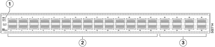
The figure shows the switch features on the port side of the chassis.
|
1 |
Beacon (BCN), Status (STS), and Environment (ENV) LEDs |
3 |
8 100/400-Gigabit QSFP-DD ports Ports 29-36 support 4x10 and 4x25G as port profile converted downlinks |
|
2 |
28 40/100-Gigabit QSFP28 ports Ports 25-28 support 4x10G and 4x25G breakout as native downlinks |
To determine which transceivers, adapters, and cables support this switch, see Cisco Transceiver Modules Compatibility Information document.
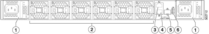
The figure shows the switch features on the power supply side of the chassis.
|
1 |
Power supply modules (1 or 2) (AC power supplies shown) with slots numbered 1 (left) and 2 (right) |
4 |
Management port (1—RJ-45 copper port) |
|
2 |
Fan modules (6) with slots numbered from 1 (left) to 6 (right) |
5 |
Management port (1—SFP optical port) |
|
3 |
Console port (1) |
6 |
USB port (1) |
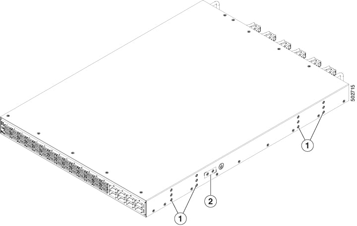
The figure shows the side of the chassis.
|
1 |
Screw holes for mounting brackets |
3 |
Grounding pad |
Depending on whether you plan to position the ports in a hot or cold aisle, you can order the fan and power supply modules with port-side intake or port-side exhaust airflow. For port-side intake airflow, the fan and power supplies have burgundy coloring. For port-side exhaust airflow, the fan and power supplies have blue coloring.
The fan and power supply modules are field replaceable. You can replace one fan module or one power supply module during operations as long as the other modules are installed and operating. If you have only one power supply installed, install the replacement power supply in the open slot before removing the original power supply.
Note |
All fan and power supply modules must have the same direction of airflow. Otherwise, the switch can overheat and shut down. |
 Caution |
If the switch has port-side intake airflow (burgundy coloring for fan modules), locate the ports in the cold aisle. If the switch has port-side exhaust airflow (blue coloring for fan modules), locate the ports in the hot aisle. If you locate the air intake in a hot aisle, the switch can overheat and shut down. |
 Feedback