Cisco Compute Hyperconverged X-Series with Nutanix in Intersight Managed Mode
Available Languages
Bias-Free Language
The documentation set for this product strives to use bias-free language. For the purposes of this documentation set, bias-free is defined as language that does not imply discrimination based on age, disability, gender, racial identity, ethnic identity, sexual orientation, socioeconomic status, and intersectionality. Exceptions may be present in the documentation due to language that is hardcoded in the user interfaces of the product software, language used based on RFP documentation, or language that is used by a referenced third-party product. Learn more about how Cisco is using Inclusive Language.
- US/Canada 800-553-2447
- Worldwide Support Phone Numbers
- All Tools
 Feedback
 Feedback
About the Cisco Validated Design Program
The Cisco Validated Design (CVD) program consists of systems and solutions designed, tested, and documented to facilitate faster, more reliable, and more predictable customer deployments. For more information, go to: http://www.cisco.com/go/designzone.
Application modernization is the foundation for digital transformation, enabling organizations to integrate advanced technologies. The key technologies include AI, IoT, cloud computing, and data analytics. Once integrated, these technologies enable businesses take advantage of digital innovations and identify opportunities for growth. These applications are diverse , distributed across geographies and deployed across data centers ,edge and remote sites. For instance, new AI workloads demand modern infrastructure to make inferences in branch offices, in retail locations, or at the network edge. The key challenge for IT Administrators is how to quickly deploy and manage infrastructure at scale, whether with many servers at a core data center or with many dispersed locations.
Hyperconverged Infrastructure (HCI) is the solution to many of today’s challenges because it offers built-in data redundancy and a smooth path to scaling up computing and storage resources as your needs grow.
The Cisco Compute Hyperconverged X-Series (CCHC) with Nutanix (Cisco HCI with Nutanix) solution helps you overcome the challenge of deploying on a global scale with an integrated workflow. The solution uses Cisco Intersight to deploy and manage physical infrastructure, and Nutanix Prism Central to manage your hyperconverged environment. Cisco and Nutanix engineers have tightly integrated our tools through APIs, establishing a joint cloud-operating model.
Whether it is at the core, edge or remote site, Cisco HCI with Nutanix provides you with a best in class solution , enabling zero touch accelerated deployment through automated workflows, simplified operations with an enhanced solution-support model combined with proactive, automated resiliency, secure cloud-based management and deployment through Cisco Intersight and enhanced flexibility with choice of compute and network infrastructure
This Cisco Validated Design and Deployment Guide provides prescriptive guidance for the design, setup, and configuration to deploy Cisco Compute Hyperconverged X-Series System with Nutanix in Intersight Managed Mode (IMM) allowing nodes to be connected to a pair of Fabric Interconnect switches and servers are centrally managed using Cisco Intersight.
For more information on Cisco Compute for Hyperconverged with Nutanix, go to: https://www.cisco.com/go/hci
This chapter contains the following:
· Audience
The intended audience for this document includes sales engineers, field consultants, professional services, IT managers, partner engineering staff, and customers deploying Cisco Compute Hyperconverged X-Series Solution with Nutanix. External references are provided wherever applicable, but readers are expected to be familiar with Cisco Compute, Nutanix, plus infrastructure concepts, network switching and connectivity, and the security policies of the customer installation.
This document describes the design, configuration, and deployment steps for Cisco Compute Hyperconverged X-Series System with Nutanix in Intersight Managed Mode (IMM).
Cisco Compute Hyperconverged X-Series with Nutanix is a hyperconverged infrastructure (HCI) solution integrating Cisco’s best-in-class Unified Computing System (Cisco UCS), datacenter networking, and SaaS Intersight infrastructure management platform with market-leading hyperconverged software from the Nutanix Cloud Platform. This solution supports Nutanix cluster configuration in Intersight for:
· Cisco HCI X-Series Modular Server with Intelligent Fabric Module (IFM) or Fabric Interconnect Module (X series Direct) in Intersight Managed Mode (IMM).
· Cisco HCI standalone rack servers in Intersight Standalone Mode (ISM) and Intersight Managed Mode (IMM).
· A mix of modular servers and rack servers is supported in the same Nutanix cluster, but they must be connected to the same pair of Fabric interconnects. This mix is not supported when using HCI-X Direct.
The Cisco HCI X-Series delivers performance, flexibility, and optimization for deployments in data centers, in the cloud, and at remote sites. This enterprise-class server offers market-leading performance, versatility, and density without compromise for workloads. Up to eight hyperconverged nodes can reside in the 7-Rack-Unit (7RU) Cisco Compute Hyperconverged X9508 Chassis, offering one of the highest densities of compute, I/O, and storage per rack unit in the industry. Cisco Compute Hyperconverged X-Series Direct module simplifies your data center, adapting to the unpredictable needs of modern applications while also providing an edge scaled for remote branch office workloads. It minimizes the IT infrastructure deployed at edge locations to achieve desired business outcomes.
Supported Cisco HCI servers claimed in Intersight can be deployed as a Nutanix cluster with policies and profiles defined in Intersight. The supported HCI servers can be added to an existing Cisco UCS-X 9508 chassis. HCI servers can co-exist with non-HCI servers in the same chassis. The co-engineered integration between Nutanix Prism Central and Cisco Intersight enables seamless zero-touch remote deployment of Nutanix clusters with Nutanix AHV or VMware ESXi hypervisors.
All the required policies for node identity, network connectivity, BIOS, boot order, and more are automatically built based on Nutanix and Cisco recommended best practices. The resulting server profile is associated with each HCI server. After gathering the cluster configuration details, Nutanix Foundation Central (FC) orchestrates the end-to-end remote cluster deployment through Cisco Intersight without any manual intervention.
Cisco Compute Hyperconverged X-Series with Nutanix software delivers pre-configured Cisco HCI servers that are ready to be deployed as nodes to form Nutanix clusters in a variety of configurations. Each server contains three software layers:
· UCS server firmware
· Hypervisor (Nutanix AHV or VMware ESXi)
· Hyperconverged software (Nutanix AOS)
Cisco Intersight provides integration support with Nutanix Prism Central to deploy Nutanix HCI clusters on Cisco UCS rack mount servers and X-series modular servers. This brings the HCI into remote edge and branch offices (ROBO) with cluster size starting from as low as one node and enterprise data centers for maximum scale. The solution provides maximum flexibility with choice of either a Cisco VIC or an Intel NIC for network connectivity leveraging existing network infrastructure without the need for additional networking gear.
For more information, go to: https://intersight.com/help/saas/configure/hci_nutanix#overview
The present solution elaborates on design and deployment details to deploy Cisco Compute Hyperconverged X-Series System for Nutanix configured in Intersight Managed Mode.
This chapter contains the following:
· Cisco UCS Fabric Interconnect
· Cisco Compute Hyperconverged X9508 Chassis
· Cisco Compute Hyperconverged X215c M8 All NVMe Nodes
As applications and data become more distributed from core data center and edge locations to public clouds, a centralized management platform is essential. IT agility will be a struggle without a consolidated view of the infrastructure resources and centralized operations. Cisco Intersight provides a cloud-hosted, management and analytics platform for all Cisco Compute for Hyperconverged, Cisco UCS, and other supported third-party infrastructure deployed across the globe. It provides an efficient way of deploying, managing, and upgrading infrastructure in the data center, ROBO, edge, and co-location environments.
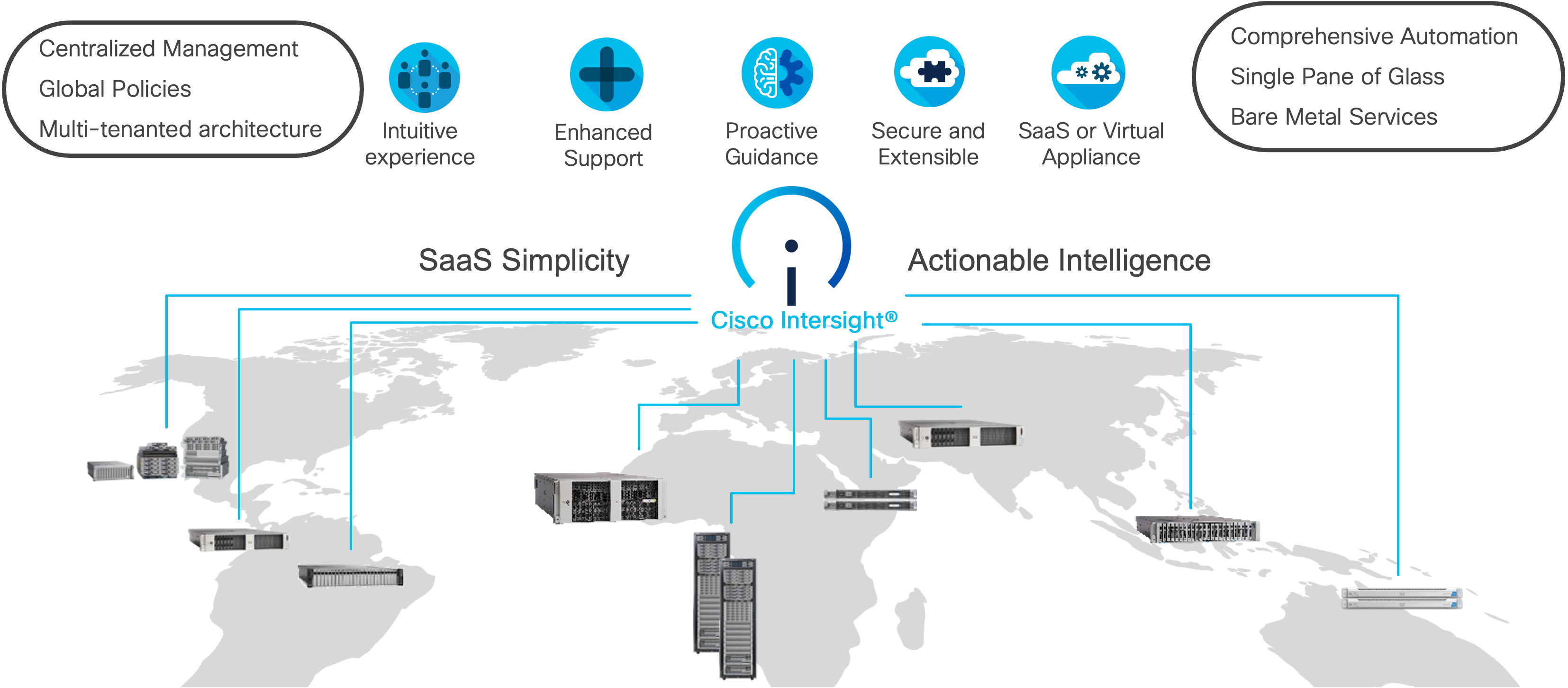
Cisco UCS combined with Cisco Intersight delivers a powerful, unified solution for modern infrastructure management. Here are the main benefits:
· Cloud-Native Unified Management: Manage UCS servers, networking, and storage from a single cloud dashboard, accessible anywhere and without on-premises management controllers.
· Automation, Consistency, and Speed: Automate deployment and configuration using templates and policies, ensuring consistent settings, faster provisioning, and reduced manual errors across all UCS resources.
· Enhanced Support Experience: A hosted platform allows Cisco to address issues platform-wide with the experience extending into TAC supported platforms.
· Programmability: End to end programmability with native API, SDK’s and popular DevOps toolsets will enable you to deploy and manage the infrastructure quickly and easily.
· Single point of automation: Automation using Ansible, Terraform, and other tools can be done through Intersight for all systems it manages.
· Unified Management: Single pane of glass, consistent operations model, and experience for managing all systems and solutions.
For more information, go to Cisco Intersight here: https://www.cisco.com/site/us/en/products/computing/hybrid-cloud-operations/intersight-platform/index.html
Cisco Intersight Virtual Appliance
Cisco Intersight Virtual Appliance delivers the management features of Intersight in an easy to deploy VMware OVA, Microsoft Hyper-V Server VM, KVM hypervisor, and Nutanix AHV hypervisor. You can deploy Intersight Virtual Appliance as a single-node virtual machine on supported hypervisors such as VMware vSphere, Microsoft Hyper-V, KVM Hypervisor, Nutanix AHV or deploy as a multi-node cluster on VMware vSphere. Intersight Virtual Appliance provides the benefits of Cisco Intersight that offers an intelligent level of management to enable customers to analyze, simplify, and automate their environments in more advanced ways than the previous generations of tools, while allowing more flexibility with additional data locality, security, and compliance requirements.
You can deploy Intersight Virtual Appliance in one of the following modes:
· Intersight Connected Virtual Appliance
· Intersight Private Virtual Appliance
· Intersight Assist
Intersight Connected Virtual Appliance delivers the management features of Intersight while allowing you to control what system details leave your premises. Intersight Connected Virtual Appliance deployments require a connection back to Cisco and Intersight services for automatic updates and access to services for full functionality. Intersight Private Virtual Appliance delivers the management features of Intersight and allows you to ensure that no system details leave your premises. Intersight Private Virtual Appliance deployments is intended for an environment where you operate data centers in a disconnected (air gapped) mode.
For more information, see https://www.cisco.com/c/en/us/td/docs/unified_computing/Intersight/b_Cisco_Intersight_Appliance_Getting_Started_Guide/m_appliance_overview.html#id_131616
Cisco Intersight offers services that allow you to manage, automate, optimize, and support your physical and virtual infrastructure. You can activate licenses for the following services on Cisco Intersight:
· Infrastructure Service and Cloud Orchestrator: Use these services to manage Cisco endpoints such as the Cisco UCS server and Cisco Hyperconverged system. For more information, see the Cisco Infrastructure Services License section: https://www.intersight.com/help/saas/getting_started/licensing_requirements/lic_infra
· Workload Optimizer: Use this service to optimize workloads across the hybrid infrastructure containers. For more information on the service and the features, see the Cisco Workload Optimizer License section: https://www.intersight.com/help/saas/getting_started/licensing_requirements/lic_iwo
The Infrastructure Service and Cloud Orchestrator service use a subscription-based license with multiple tiers. You can choose the required Cisco UCS Server volume tier for the selected subscription term.
Cisco Intersight Infrastructure Services licensing model was simplified to offer the following two tiers:
· Cisco Intersight Infrastructure Services Essentials: The Essentials license tier offers server management with global health monitoring, inventory, proactive support through Cisco TAC integration, multi-factor authentication, along with SDK and API access.
· Cisco Intersight Infrastructure Services Advantage: The Advantage license tier offers advanced server management with extended visibility, ecosystem integration, and automation of Cisco and third-party hardware and software, along with multi-domain solutions.
There are two different license types for Intersight:
· Intersight CVA/SaaS: Used to assign license tiers to targets claimed in SaaS and Connected Virtual Appliance (CVA).
· Intersight PVA: Used to assign license tiers to targets claimed on Private Virtual Appliance (PVA) only.
Intersight requires physical servers to belong to a Licensing tier. This can be done by providing a default tier or setting it individually from Servers View. The enforcement of Cisco Infrastructure Services licenses occurs at the server level and is not dependent on UCS domains. All servers with valid licenses can use the licensed features. As a new Intersight user, you can evaluate Intersight for a period of 90 days without a registered license.
As a new Intersight user, you can evaluate Intersight for a period of 90 days without a registered license. As long as an active license has not been activated, you can initiate a trial at any point in time, not just during the initial account creation. Note that the trial can only be activated once. During this Trial period, the features requiring licenses are available without registering Intersight with Cisco Smart Licensing. You can view details of the Trial period in the Licensing page.
The Cisco UCS 6536 Fabric Interconnect (FI) is a core part of the Cisco Unified Computing System, providing both network connectivity and management capabilities for the system. The Cisco UCS 6536 Fabric Interconnect offers line-rate, low-latency, lossless 10/25/40/100 Gigabit Ethernet, Fibre Channel, NVMe over Fabric, and Fibre Channel over Ethernet (FCoE) functions.
The Cisco UCS 6536 Fabric Interconnect provides the communication backbone and management connectivity for the Cisco UCS X-Series compute nodes, Cisco UCS X9508 X-Series chassis, Cisco UCS B-Series blade servers, Cisco UCS 5108 B-Series server chassis, and Cisco UCS C-Series rack servers. All servers attached to a Cisco UCS 6536 Fabric Interconnect become part of a single, highly available management domain. Additionally, by supporting a unified fabric, Cisco UCS 6536 Fabric Interconnect provides both LAN and SAN connectivity for all servers within its domain.
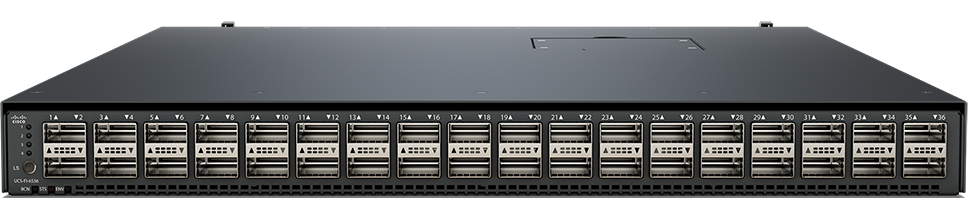
The Cisco UCS 6536 Fabric Interconnect is built to consolidate LAN and SAN traffic onto a single unified fabric, saving on Capital Expenditures (CapEx) and Operating Expenses (OpEx) associated with multiple parallel networks, different types of adapter cards, switching infrastructure, and cabling within racks.
The Cisco UCS 6536 Fabric Interconnect can be managed through Cisco Intersight. The UCS 6536 Fabric Interconnect supports Intersight Managed Mode (IMM), which enables full manageability of Cisco UCS elements behind the UCS 6536 FI through Cisco Intersight. UCS 6536 Fabric Interconnect in Intersight managed mode will support Cisco UCS product models, including Cisco UCS X-Series Servers, Cisco UCS B-Series Blade Servers, and C-Series Rack Servers, as well as the associated storage resources and networks. For more details, go to: https://www.cisco.com/c/en/us/products/collateral/servers-unified-computing/ucs6536-fabric-interconnect-ds.html
Cisco Compute Hyperconverged X9508 Chassis
The Cisco Compute Hyperconverged X-Series System with Nutanix combines the operational simplicity of Nutanix Cloud Platform (NCP) with the efficiency, flexibility, and sustainability of the Cisco UCS X-Series Modular System. The X-Series system comprises modular components that can be assembled into systems through the Cisco Intersight cloud-operations platform.
The image below shows Cisco Compute Hyperconverged X-Series System, front (left) and back (right):
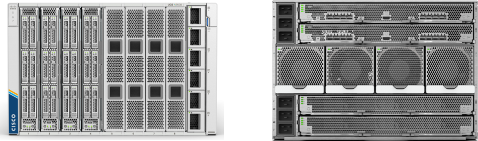
The Cisco Compute Hyperconverged X-Series System is engineered to be adaptable and future-ready. The 7-Rack-Unit (7RU) chassis has 8 x front-facing flexible slots. These can house a combination of hyperconverged nodes, compute nodes, and a pool of future I/O resources that may include GPU accelerators, disk storage, and nonvolatile memory. 2 x 9108 25G Intelligent Fabric Modules (IFMs) at the top of the chassis that connect the chassis to upstream 6400 Series Fabric Interconnects or 6500 Series fabric interconnects. At the bottom are slots ready to house future I/O modules that can flexibly connect the compute modules with I/O devices. We call this connectivity Cisco UCS X-Fabric technology because “X” is a variable that can evolve with new technology developments.
Cisco Compute Hyperconverged X-Series with Nutanix is supported on both the Cisco Compute Hyperconverged X-Series and Cisco Compute Hyperconverged X-Series Direct platforms. The primary distinction between these two platforms lies in the integration of the fabric module. The X-Series Direct features integrated fabric interconnects, which are particularly beneficial for edge, and small- or remote-office use cases, offering a self-contained system without the need for top-of-rack switches.
The X-Series, equipped with fabric interconnects, enables seamless scalability up to 160 servers, distributed across 20 chassis, each containing up to 8 nodes. This architecture simplifies management by eliminating the need for dedicated chassis management and blade switches, while also reduces cabling requirements, thereby minimizing complexity, and enhancing operational efficiency.
For more information, see https://www.cisco.com/c/en/us/products/collateral/hyperconverged-infrastructure/hyperconverged-x9508-chassis-ds.html
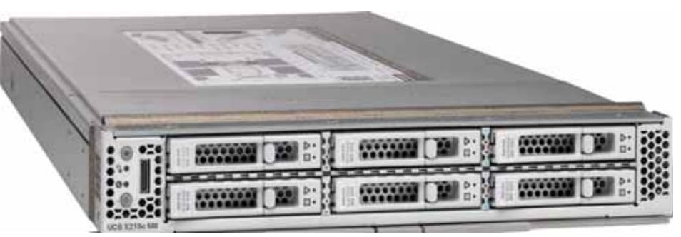
Cisco Compute Hyperconverged X215c M8 All NVMe Nodes
Cisco Compute Hyperconverged x215c M8 All NVMe Node delivers performance, flexibility, and optimization for deployments in data centers, in the cloud, and at remote sites. This enterprise-class server offers market-leading performance, versatility, and density without compromise for workloads. Up to 8 compute nodes can reside in the 7-Rack-Unit (7RU) Cisco UCS X9508 Server Chassis, offering one of the highest densities of compute, I/O, and storage per rack unit in the industry.
The Cisco Compute Hyperconverged x215c M8 All NVMe Node family powers 5th Gen AMD EPYC processors with 150 percent more cores per socket designed using AMD’s chiplet architecture. With advanced features such as AMD Infinity Guard, compute-intensive applications will see significant performance improvements and reap other benefits such as power and cost efficiencies.
For more details, see: https://www.cisco.com/c/en/us/products/collateral/hyperconverged-infrastructure/compute-hyperconverged/x215c-m8-all-nvme-node-ds.html
For Cisco Compute Hyperconverged with Nutanix HCIXNX215c M8 All NVMe Compute Node Spec sheet, see: https://www.cisco.com/c/dam/en/us/products/collateral/hyperconverged-infrastructure/compute-hyperconverged-hcixnx215c-m8-specsheet.pdf
For ordering information, see the Cisco Compute Hyperconverged X-Series M8 with Nutanix (CCHC + N) Ordering Guide.
This chapter contains the following:
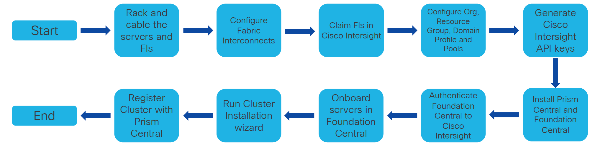
The deployment architecture for Cisco Compute Hyperconverged X-Series with Nutanix in Intersight Managed Mode (IMM) is detailed in Figure 2. The entire Day0 deployment is managed through Cisco Intersight and Nutanix Foundation Central enabled through Prism Central.
Each Compute Hyperconverged X215c M8 All NVMe server nodes is configured with the following:
· 1 x AMD EPYC 9355P 32-Core Processor
· 768 GB DDR5 memory
· 2 x 480GB M.2 card managed through M.2 RAID controller
· 6 x 1.9 TB NVMe managed through NVMe-direct-U.3 controller
· 1 x Cisco VIC 15230 2x 100G mLOM X-Series w/Secure Boot
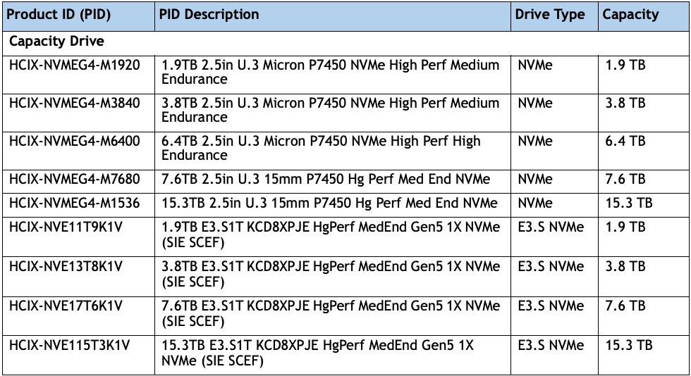
Note: Cisco Compute Hyperconverged HCIXNX215c M8 All-NVMe Node support both NVMe U.3 as well E3.S NVMe drives. Approved configuration is either option 1: three to six U.3 NVMe drives or option 2: three to eight E3.S NVMe capacity drives. However, E3.S NVMe and U.3 NVMe drives cannot be mixed.
· This solution used NVMe U.3 drives but this solution can also be deployed using E3.S PCIe NVMe drives.
· The Cisco Compute Hyperconverged HCIXNX215c M8 All-NVMe Compute Node has one front mezzanine connector that can accommodate one of the following mezzanine cards:
· HCIX-X10C-PT4F: Compute Node compute pass through controller supports up to 6 NVMe U.2/U.3 drives
· HCIX-X10C-PTE3: Compute Pass Through Controller supports up to eight E3.S PCIe NVMe drives.
· Cisco supports the following NVMe and E3.S drives as shown below:
Note: This document illustrates the Cisco HCIXNX215c M8 All-NVMe/All-Flash Servers specifications as validated in this document. You have several options to configure CPU, Memory, Network cards, GPUs and Storage drives as detailed in this spec sheet: https://www.cisco.com/c/dam/en/us/products/collateral/hyperconverged-infrastructure/compute-hyperconverged-hcixnx215c-m8-specsheet.pdf
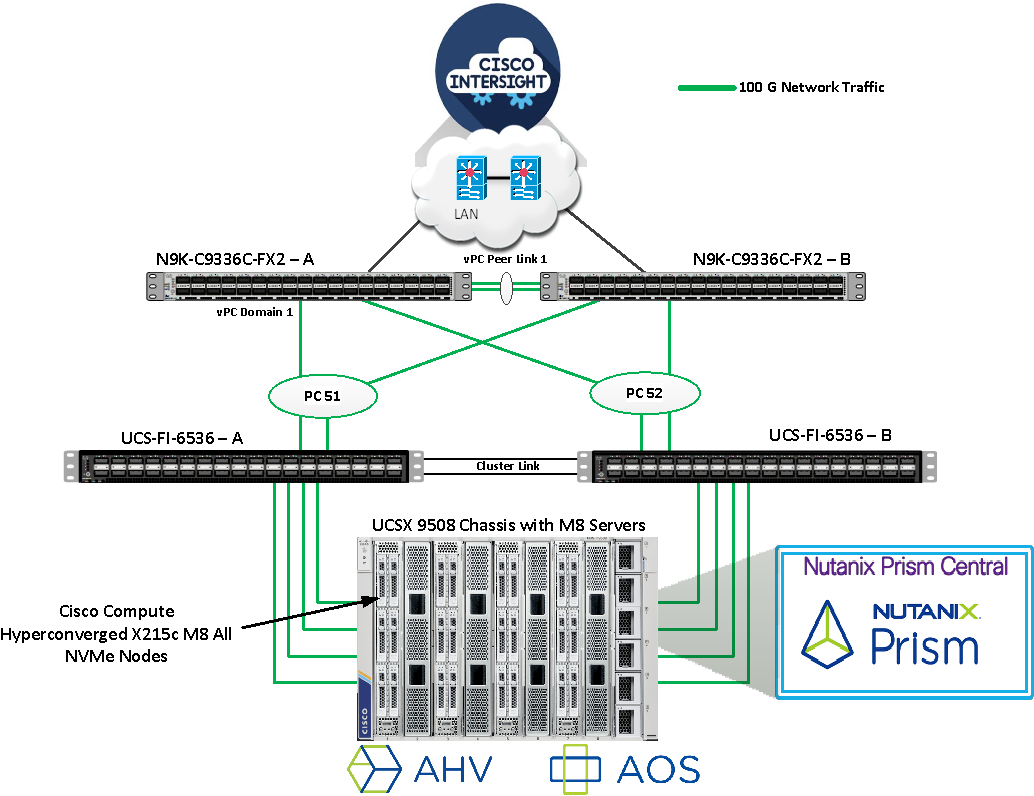
Figure 3 illustrates the cabling diagram for fabric interconnects in this deployment mode.
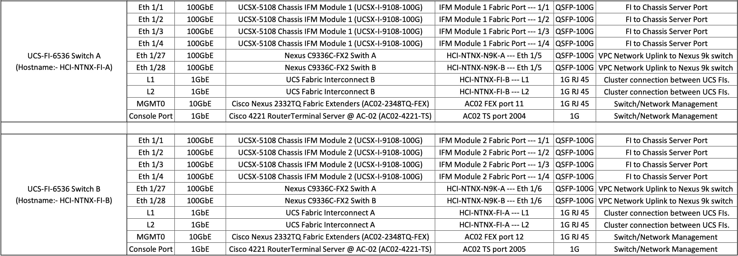
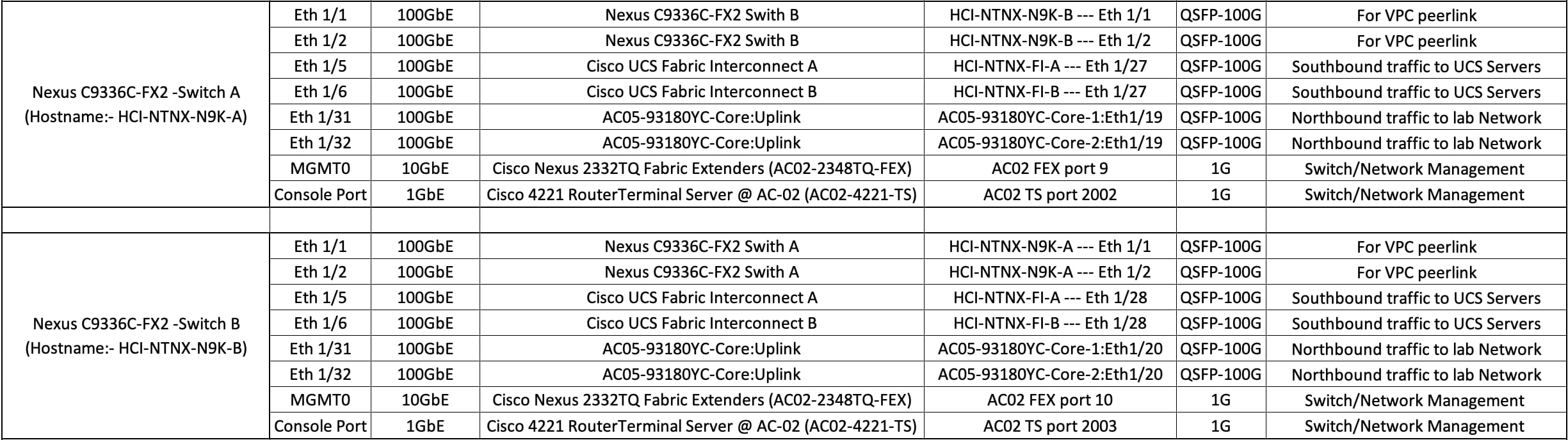
Figure 4 illustrates the cabling diagram for Nexus N9k-9336C-FX2 in this deployment mode.
Cisco Intersight uses a subscription-based license with multiple tiers. Each Cisco automatically includes a Cisco Intersight Essential trial license when you access the Cisco Intersight portal and claim a device.
More information about Cisco Intersight Licensing and the features supported in each license can be found here: https://intersight.com/help/saas/getting_started/licensing_requirements/lic_intro
In this solution, using Cisco Intersight Advantage License Tier enables the following:
· Configuration of Server Profiles for Nutanix on Cisco UCS X-Series Blade Servers
· Integration of Cisco Intersight with Foundation Central for Day 0 to Day N operations
Table 1 lists the software components and the versions validated for the Cisco Compute Hyperconverged X-Series with Nutanix in Intersight Managed Software Components.
Table 1. Software components and versions
| Component |
Version |
| Cisco Nexus 9000 C9336C-FX2 Switch |
BIOS: version 05.53, NXOS: version 10.4(5) |
| Cisco UCS Fabric Interconnect |
Bundle Version: 4.3(6.250084), NX-OS Version 9.3(5)I43(6b) |
| Cisco UCSX-215C M8 All NVMe server |
Bundle Version: 5.4(0.250048) |
| Foundation Central |
1.8.2 |
| Prism Central deployed on ESXi cluster |
pc.2022.6.0.12 (pc.2022.6.0.12.ova) pc.7.3.1.1 (pc.7.3.1.1.ova) |
| AHV Installer (ISO) |
Version: 10.3.1.1 (Filename: AHV-DVD-x86_64-10.3.1.1-11.iso) |
| AOS Installer (ISO) |
Version: 7.3.1.1 (Filename: nutanix_installer_package-release-ganges-7.3.1.1-stable-1d17e9eef51d876f64c25d416c1da4bfd4b04d3b-x86_64.tar.gz) |
| Cisco Intersight Managed Mode (IMM) Transition Tool |
Version: v5.1.1 (Filename: MM-Transition-5.1.1.ova) |
This chapter contains the following:
· Configure Policies for Cisco UCS Domain
· Configure Cisco UCS Domain Profile
· Configure Foundation Central
This chapter describes the solution deployment for Nutanix on Cisco UCS X-Series Blade Servers in Intersight Managed Mode (IMM), with step-by-step procedures for implementing and managing the deployment. Cisco UCS X-Series connectivity in Intersight Managed Mode (IMM) relies on the Unified Fabric, which consolidates management and production traffic through a pair of UCS 6500-series Fabric Interconnects connected to the chassis via Intelligent Fabric Modules (IFMs). IMM allows Cisco Intersight to control and manage the entire UCS domain—including X-Series servers—using a cloud-based policy and operations framework, without local UCS Manager.
To ensure the correct installation process is being followed for Cisco Compute Hyperconverged with Nutanix, see the following flowchart to choose the correct documentation for the system being installed:
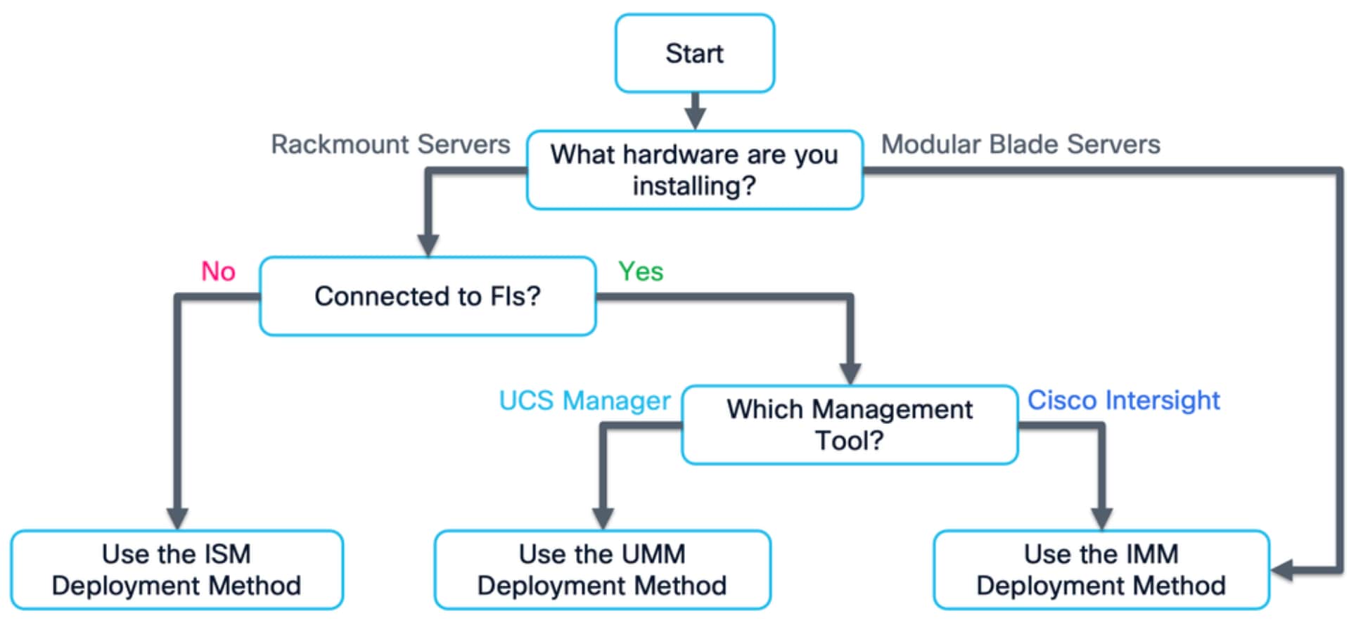
Note: A Field Guide covering the installation and initial configuration of Cisco Compute Hyperconverged with Nutanix systems using Intersight Managed Mode for Cisco UCS X-Series modular blade servers and C-series rackmount servers. Intersight Managed Mode (IMM) is the term for X-series and C-series servers connected to Cisco UCS Fabric Interconnects, which are managed entirely via Cisco Intersight. This guide is intended for technical training and educational purposes, for all who wish to install Nutanix on Cisco UCS based hardware following our supported hardware and software integrations and compatibility lists. https://community.cisco.com/t5/unified-computing-system-knowledge-base/cisco-compute-hyperconverged-with-nutanix-imm-field-guide/ta-p/5219852
This document presents our best practices and recommendations as of the time of publishing and will be updated periodically. Please refer to the document history at the beginning to ensure you are using the most current version available.
Figure 5 shows the high-level configuration of installation of Nutanix clusters on Cisco UCS X-series servers in Intersight Managed Mode (IMM) such as X-series blades in a chassis that are connected to Cisco UCS Fabric Interconnects and managed by Cisco Intersight.
Cisco Intersight Managed Mode standardizes policy and operation management for Cisco UCS X-Series. The following are the high-level procedures to configure Cisco UCS X-Series in Intersight Managed Mode (IMM).
Procedure 1. Configure Cisco UCS Fabric Interconnects for Cisco Intersight Managed Mode
During the initial configuration, for the management mode, the configuration wizard enables you to choose whether to manage the fabric interconnect through Cisco UCS Manager or the Cisco Intersight platform.
Note: For this solution, we chose Intersight Managed Mode (IMM) for validating this Nutanix deployment.
Step 1. Verify the following physical connections on the fabric interconnect:
- The management Ethernet port (mgmt0) is connected to an external hub, switch, or router.
- The L1 ports on both fabric interconnects are directly connected to each other.
- The L2 ports on both fabric interconnects are directly connected to each other.
Step 2. Connect to the console port on the first fabric interconnect and configure the first FI as shown below:
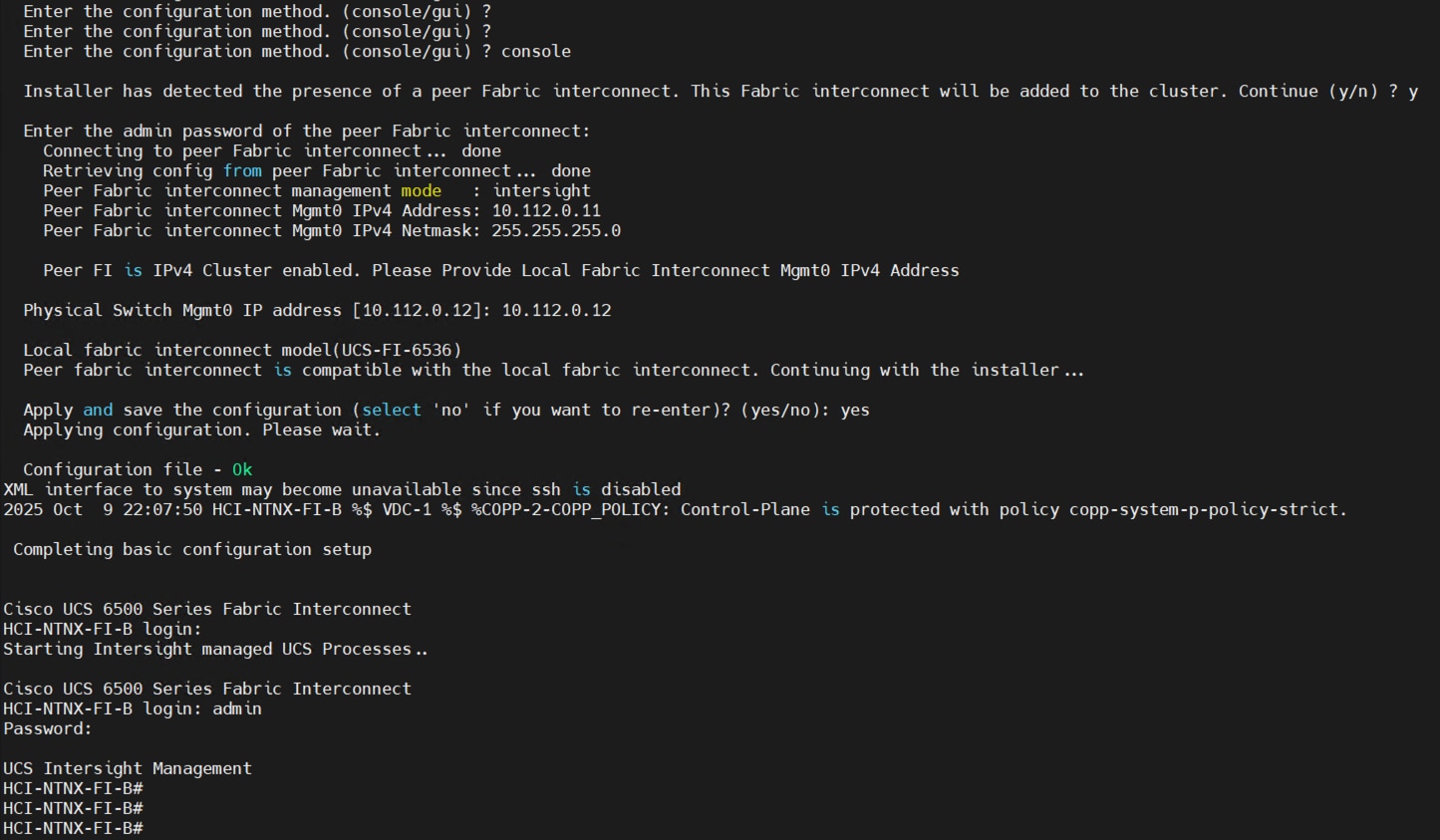
Step 3. Connect the console port on the second fabric interconnect B and configure it as shown below:
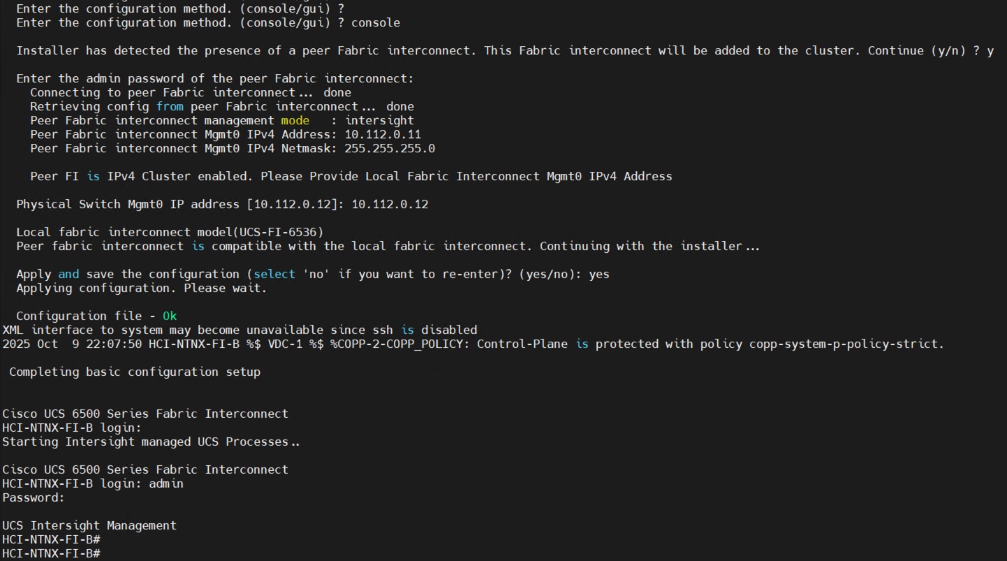
Step 4. After configuring both the FI management addresses, open a web browser and navigate to the Cisco UCS fabric interconnect management address as configured. If prompted to accept security certificates, accept, as necessary.
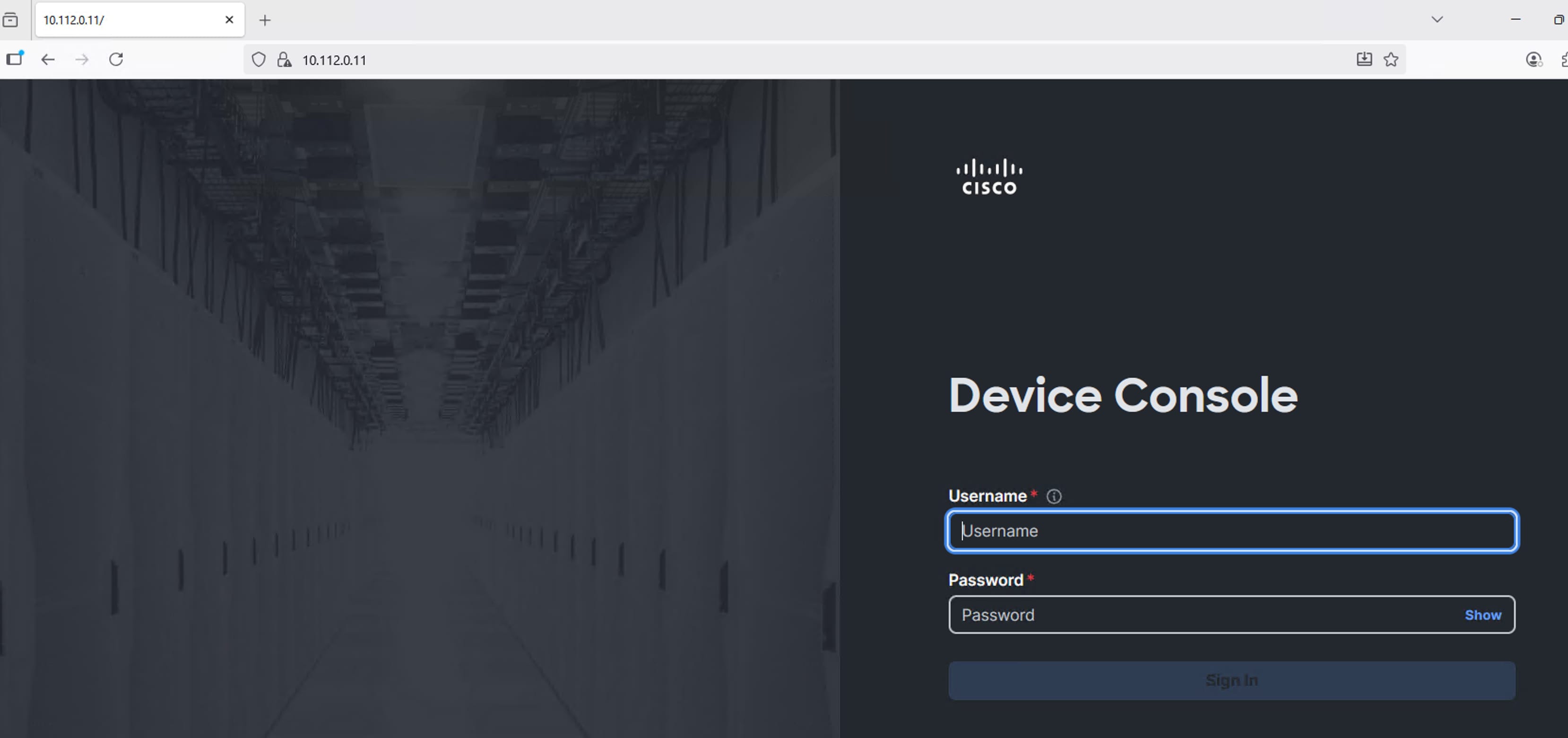
Step 5. Log into the device console for FI-A by entering your username and password.
Step 6. Go to the Device Connector tab and get the DEVICE ID and CLAIM Code as shown below:
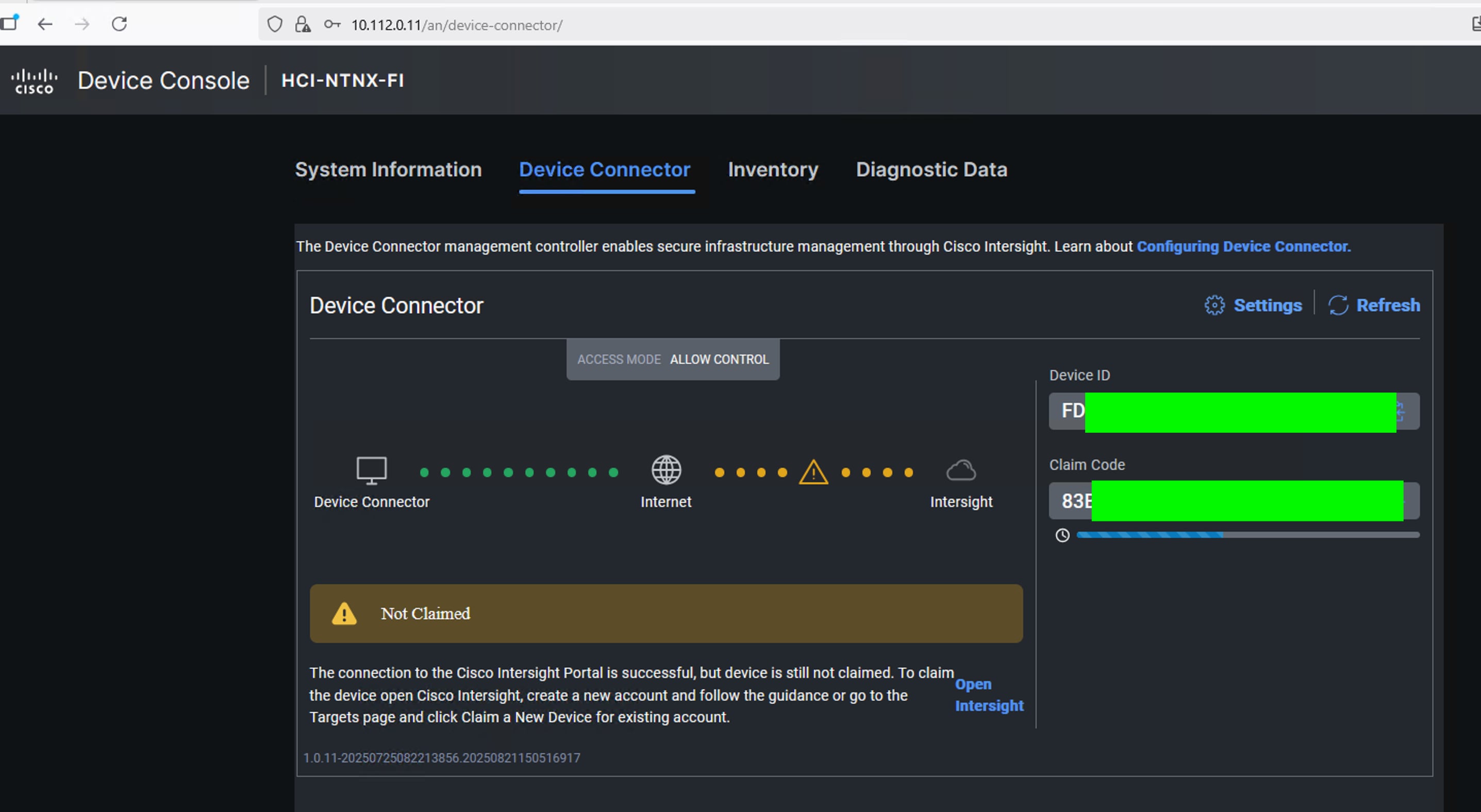
Note: After setting up the Cisco UCS fabric interconnect for Cisco Intersight Managed Mode, FIs can be claimed to a new or an existing Cisco Intersight account.
Note: When a Cisco UCS fabric interconnect is successfully added to the Cisco Intersight platform, all subsequent configuration steps are completed in the Cisco Intersight portal.
Procedure 2. Claim Fabric Interconnects in Cisco Intersight Platform
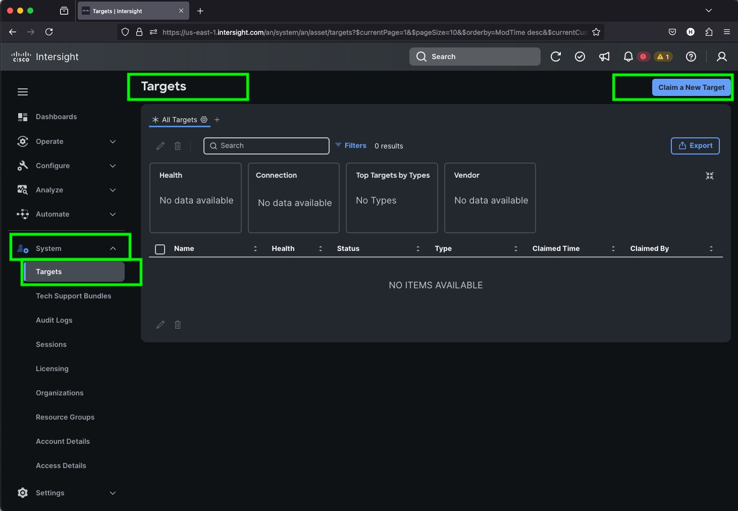
Step 1. After getting the device id and claim code of FI, go to https://intersight.com/.
Step 2. Sign in with your Cisco ID or if you don’t have one, click Sing Up and setup your account.
Note: We created the Nutanix-AMD-CVD account for this solution.
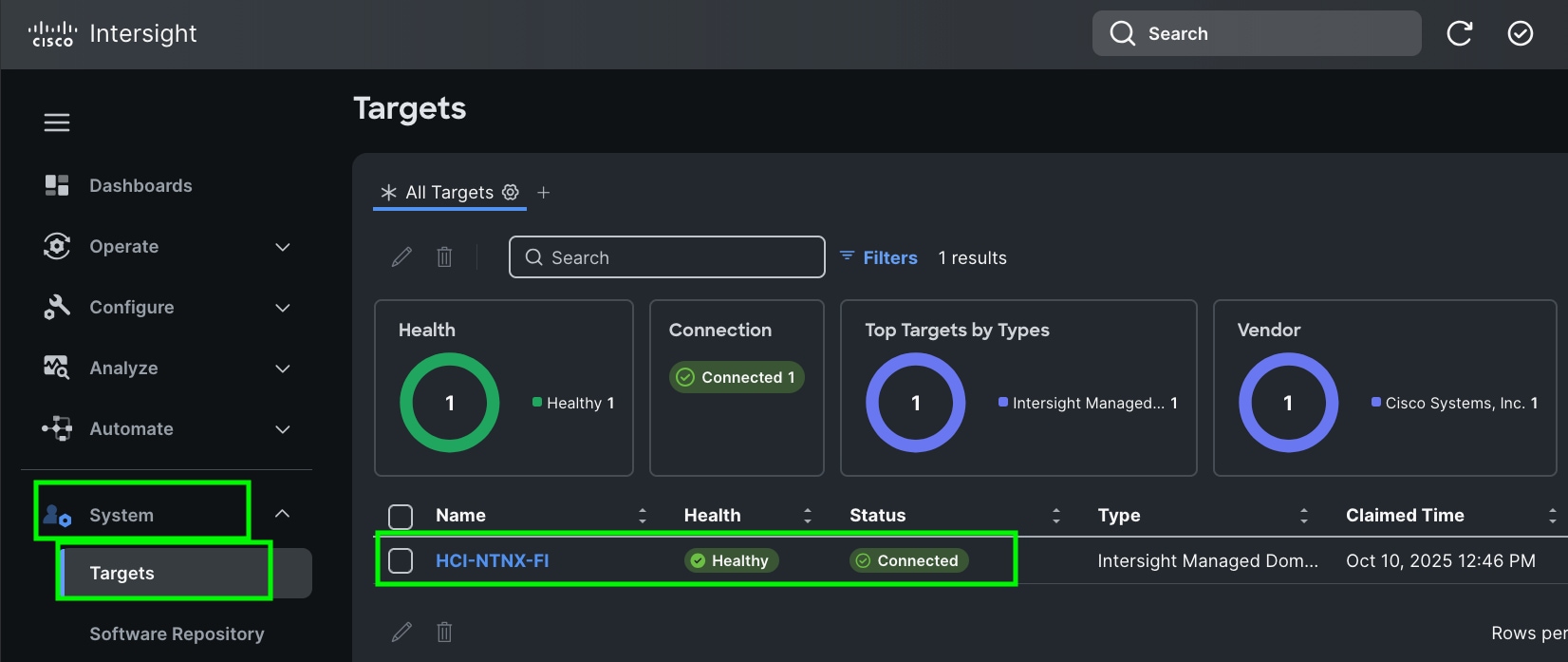
Step 3. After logging into your Cisco Intersight account, go to > System > Targets > Claim a New Target.
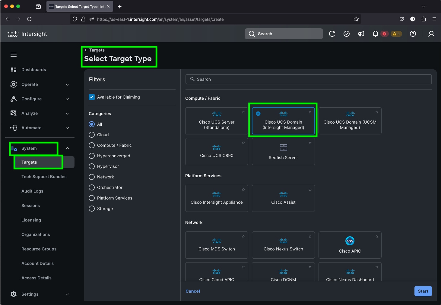
Step 4. For the Select Target Type, select Cisco UCS Domain (Intersight Managed) and click Start.
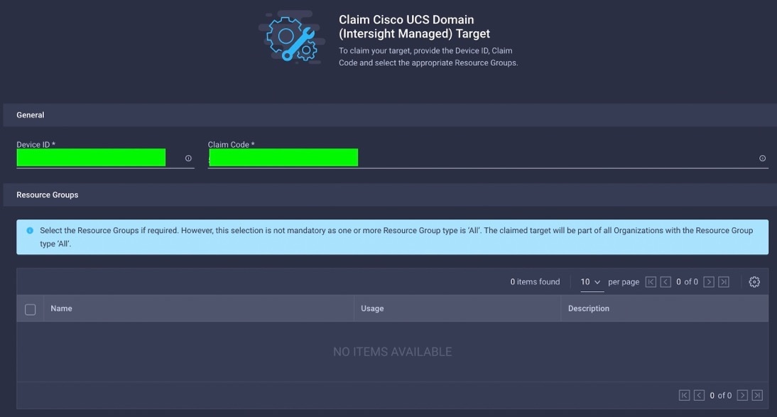
Step 5. Enter the Device ID and Claim Code which was previously captured. Click Claim to claim this domain in Cisco Intersight.
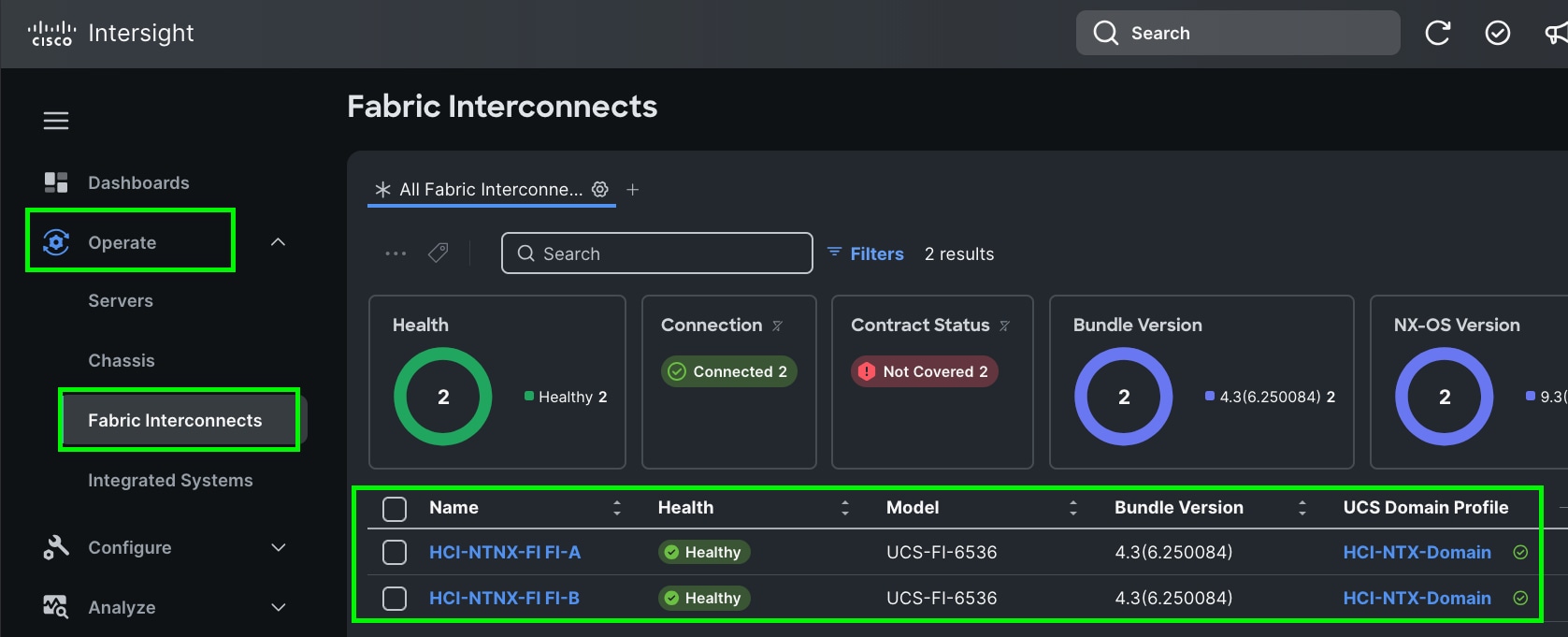
When you claim this domain, you can see both FIs under this domain and verify it’s under Intersight Managed Mode:
Cisco UCS Fabric Interconnect from the OPERATE tab shows details and Management Mode as shown below.
Note: Upgrade the fabric interconnect firmware if necessary.
Step 6. (Optional) Role-based Access Control (RBAC) in Cisco Intersight:
- Create one or more Resource Groups (optional): Create a Resource Group to organize the physical servers into a group that is placed into an organization.
- Create one or more Organizations (optional): Create an Organization and associate it with one or more Resource Groups. If you share the organization with another one, you cannot select a resource group. Organizations can either be associated with a resource group, or shared with another org, but not both.
Procedure 3. Configure Cisco Intersight Account and System Settings
Step 1. Go to System > Account Details. For more details: https://intersight.com/help/saas/system/settings
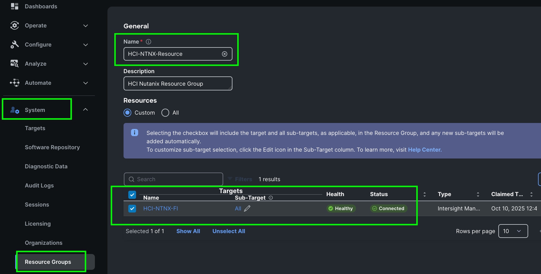
Step 2. In the System tab > Select Resource Group. Create New resource group.
Step 3. Select Targets to be part of this resource group and click Create.
Note: For this solution, we created new resource group as “HCI-NTNX-Resource” and selected all the sub-targets as shown below.
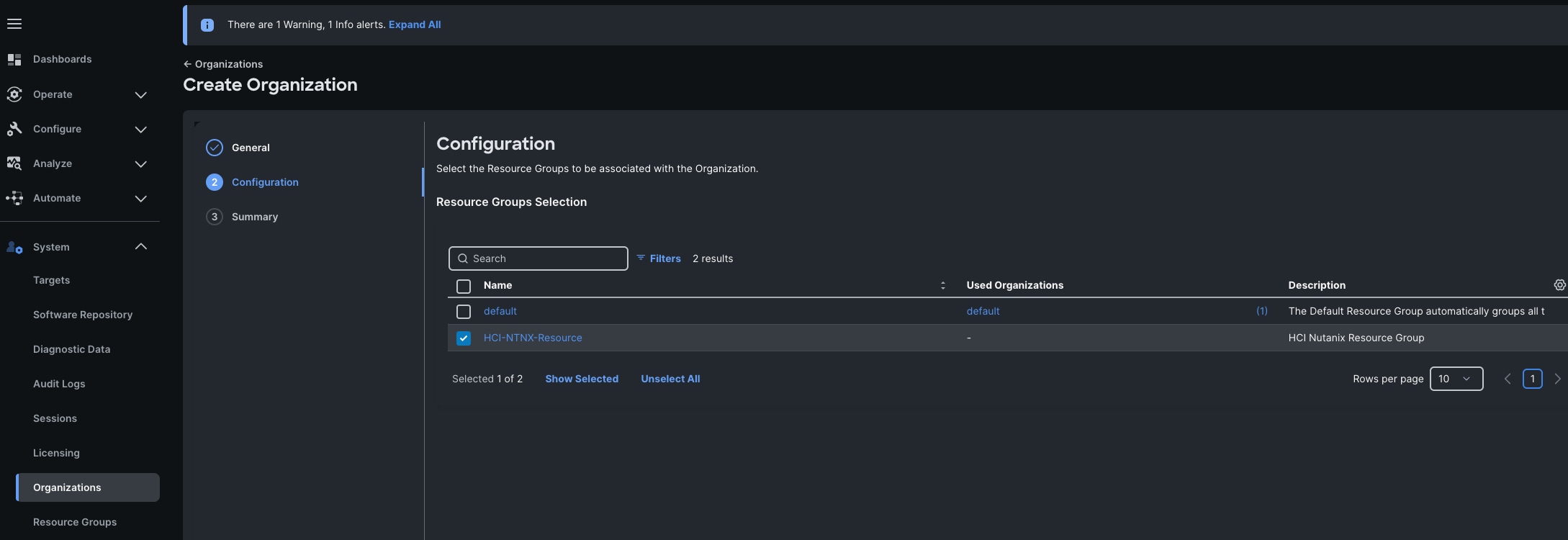
Step 4. We configured the HCI-NTNX-Org group for this solution. Go to System menu, select Organizations then click Create Organization.
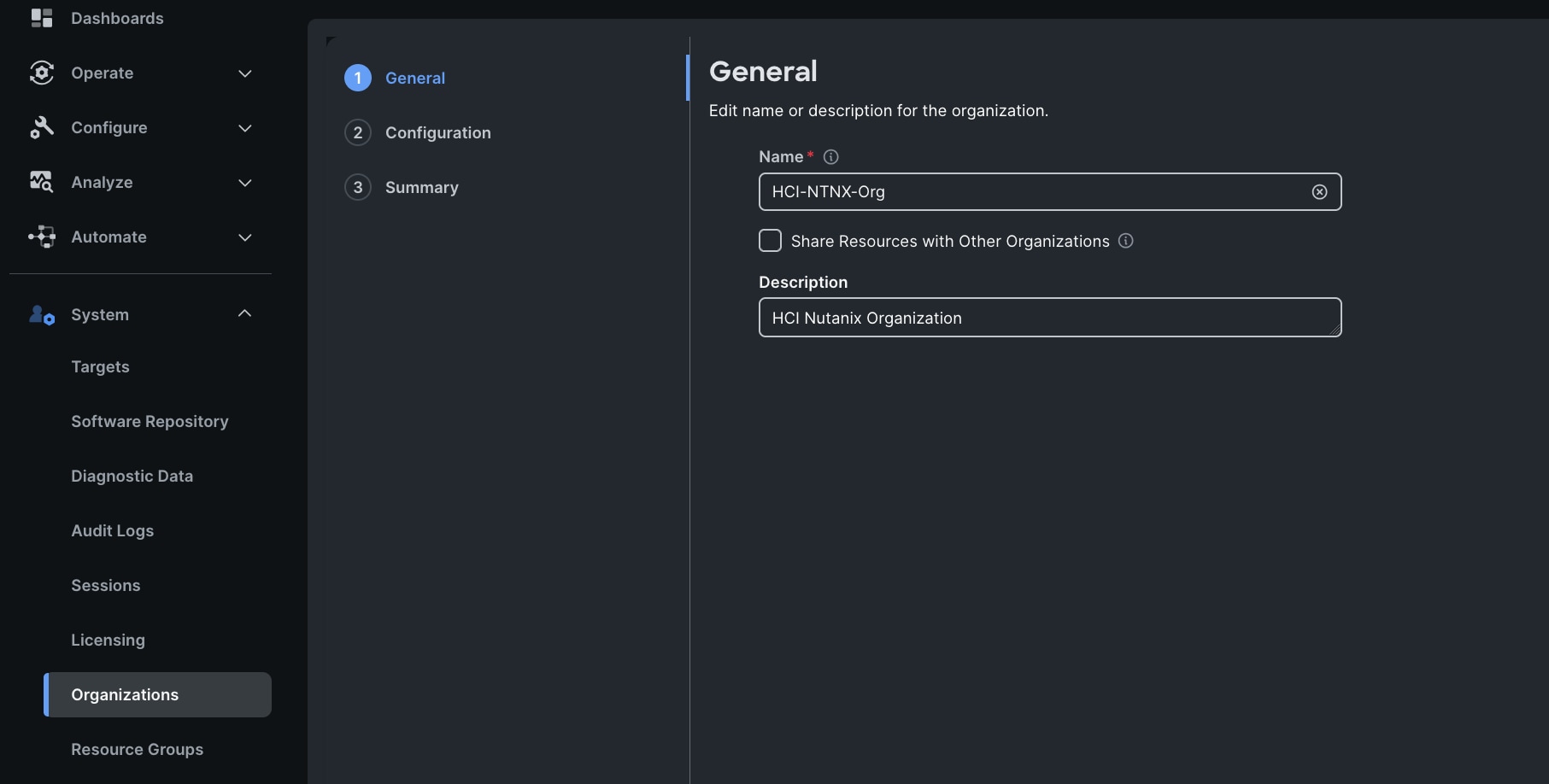
Step 5. Enter the name for the new Organization creation.
Step 6. (Optional) Check the box to share resources with other organizations. Click Next.
Step 7. In the configuration option, select the Spk-Resource configured earlier and click Next.
Step 8. Verify the summary page and then click Create to create organization with resource group for this deployment as shown below:
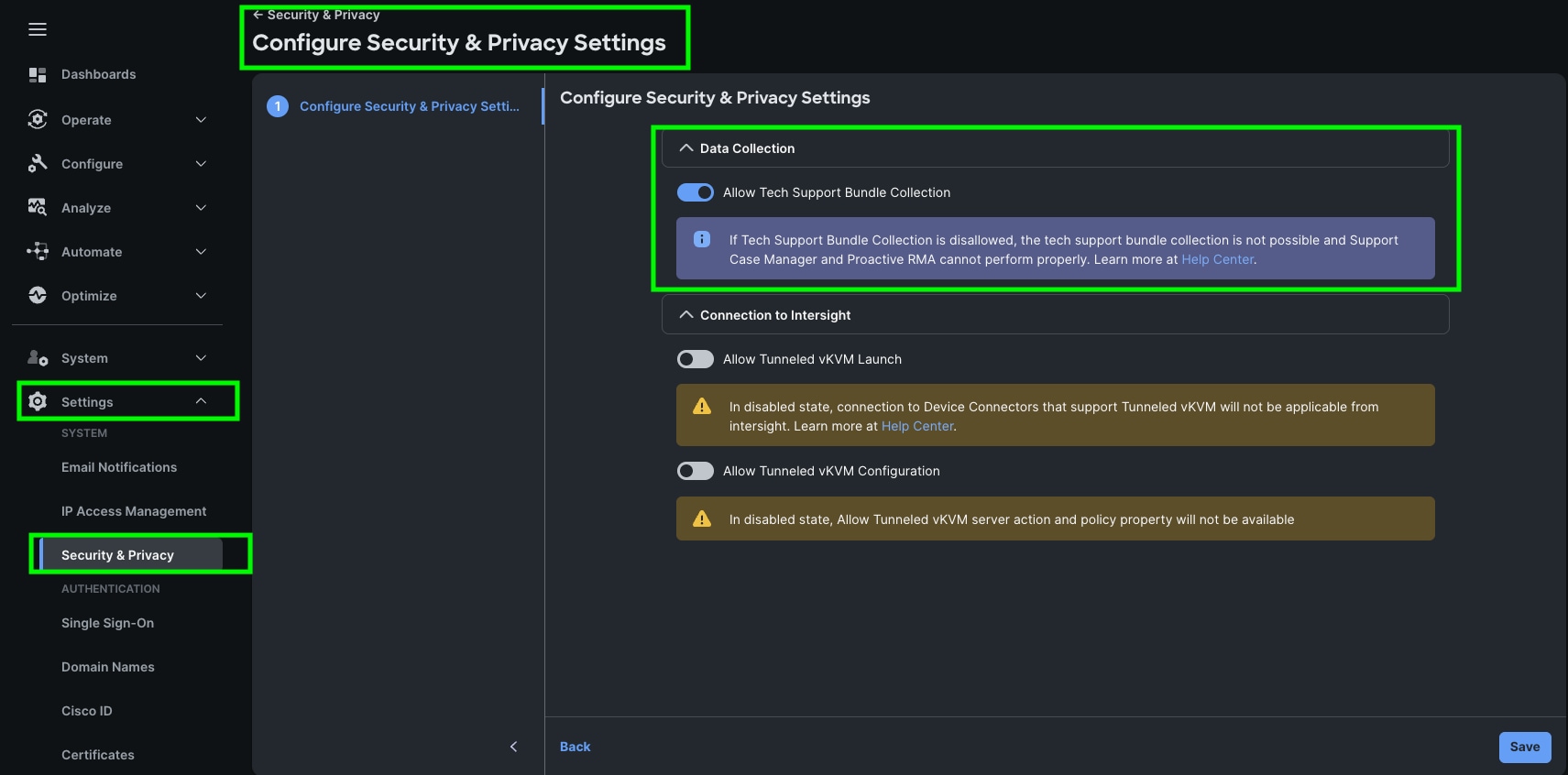
Step 9. To configure allowing tech support bundle collection, go to Settings > Security & Privacy > and enable the option and then click Save.
Note: For this solution we disabled Tunneled vKVM Launch and configuration.
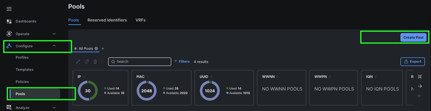
Create Prerequisite Pools: Two pools must be created before the Nutanix cluster is created; a MAC Address Pool and an IP Address Pool for the blades’ IMC access, plus an optional UUID pool to assign unique identifiers to each blade.
Note: Create an IP Address Pool in the appropriate Organization with valid DNS, and a block with enough addresses to assign 1 to each server in the cluster, plus extras for future growth. The IP addresses must be in the same layer 2 subnet as the Fabric Interconnects’ mgmt0 interfaces, which is known as Out-of-Band IMC access. Alternatively, In-Band IMC access uses a VLAN via the Fabric Interconnects’ Ethernet uplinks. The VLAN must be defined in the Domain Profile and VLAN policy, and the IP addresses defined in this pool must be from the layer 2 subnet carried by that VLAN.
Step 1. Go to > Configure > Pools > and then click Create Pool.
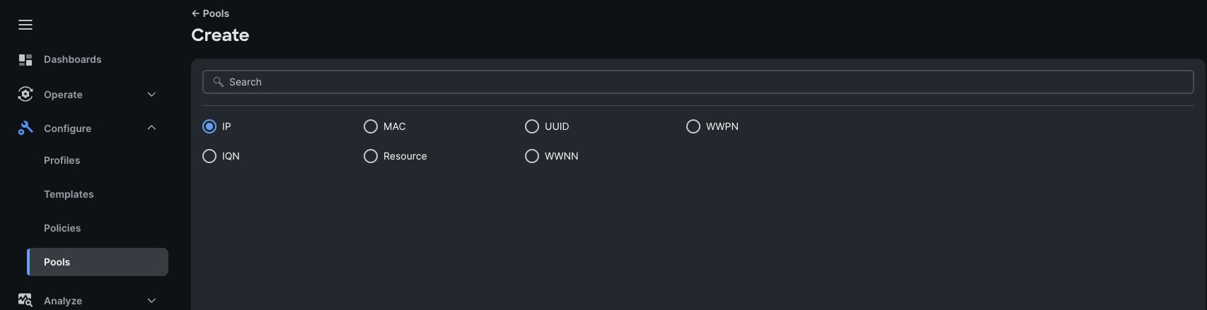
Step 2. Select IP as shown below to create the IP Pool.
Step 3. In the IP Pool Create section, for Organization select HCI-NTNX-Org, enter the Policy name Ntx-IP-Pool, and click Next.
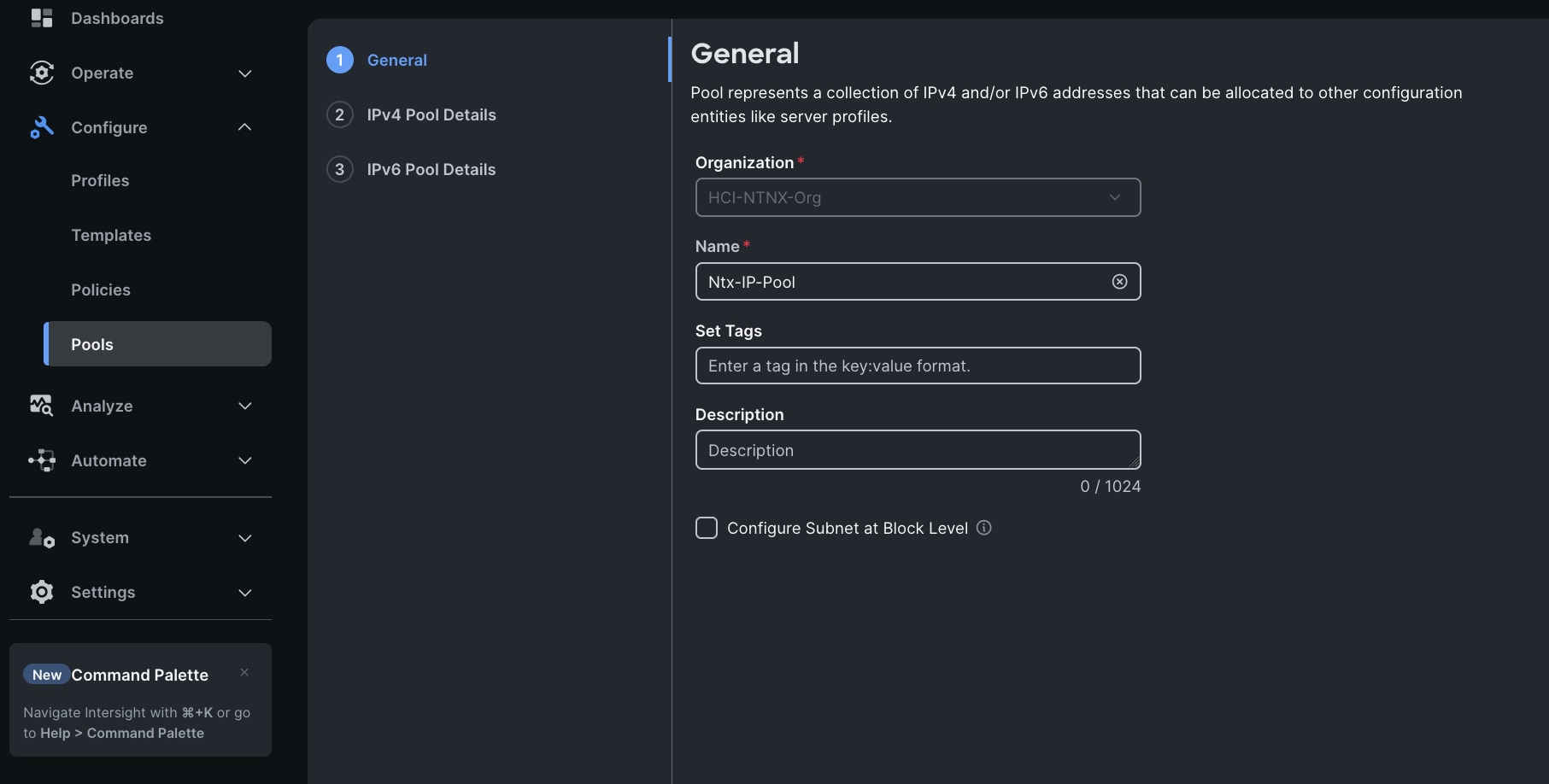
Step 4. Enter Netmask, Gateway, Primary DNS, IP Blocks and Size according to your environment and click Next.

Note: For this solution, we did not configure the IPv6 Pool. Keep the Configure IPv6 Pool option disabled and click Create to create the IP Pool.
Step 1. Create a MAC Address Pool in the appropriate Organization with a unique starting block address, and with enough addresses to assign at least 2 to each server in the cluster, plus extras for future growth.
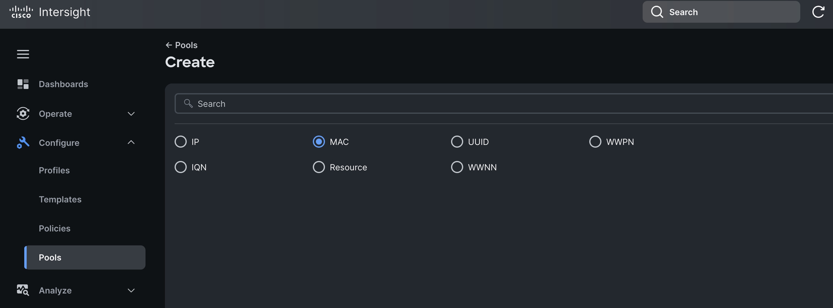
Step 2. To configure a MAC Pool for a Cisco UCS Domain profile, go to > Configure > Pools > and click Create Pool. Select option MAC to create MAC Pool.
Step 3. In the MAC Pool Create section, for the Organization, select HCI-NTNX-Org and enter the Policy name Ntx-MAC-Pool. Click Next.
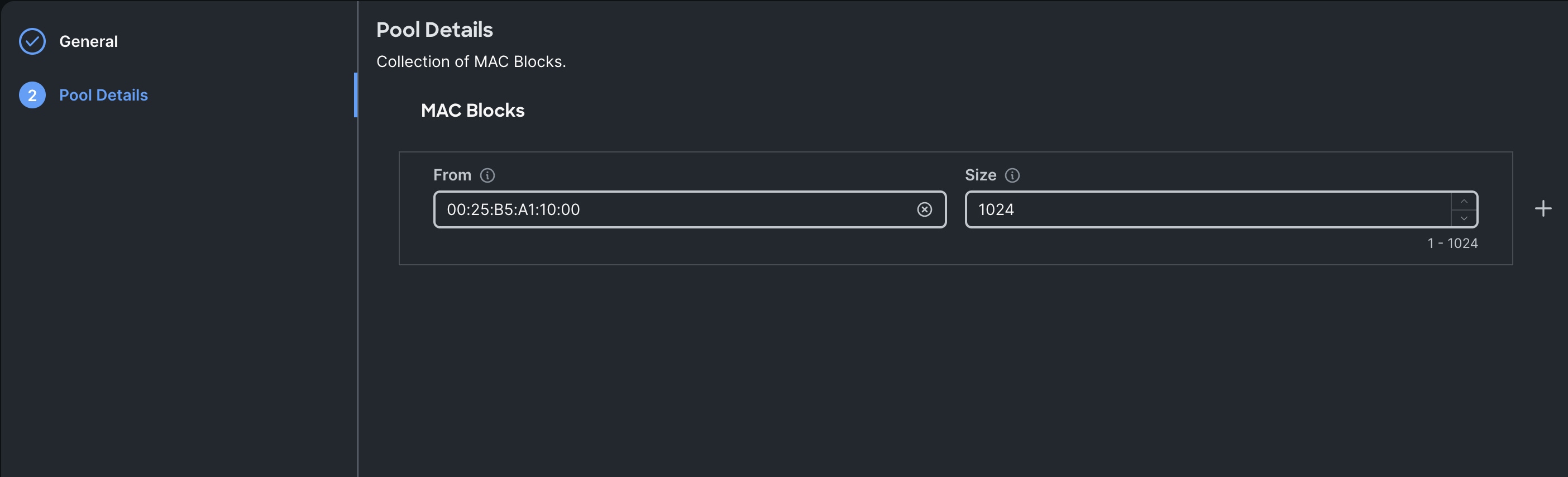
Step 4. Enter the MAC Blocks from and Size of the pool according to your environment and click Create.
Procedure 6. Configure UUID Pool
Create a UUID Pool in the appropriate Organization with a unique prefix and a block with a unique starting address, and with enough addresses to assign 1 to each server in the cluster, plus extras for future growth. If a pool is not used the UUID of the blade servers’ profiles will be based on the hardware UUID, which could limit the ability to move the profile to a different server in the future.
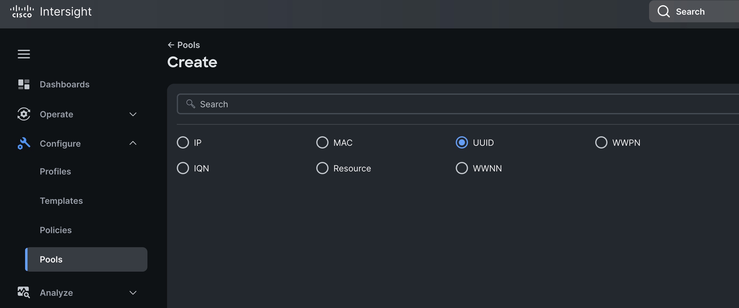
Step 1. To create UUID Pool for a Cisco UCS, go to > Configure > Pools > and click Create Pool. Select option UUID.
Step 2. In the UUID Pool Create section, for the Organization, select HCI-NTNX-Org and enter the Policy name Ntx-UUID-Pool. Click Next.
Step 3. Select Prefix, UUID block and size according to your environment and click Create.
Procedure 7. Generate Cisco Intersight API keys
The Cisco Intersight API keys allow authentication and communication of Nutanix Foundation Central with Cisco Intersight. Further, once the communication channel is setup, Nutanix Foundation Central can identify the Cisco X-Series nodes claimed in Intersight and configure Server profile and upgrade firmware of Cisco UCS X-Series Rack Servers in IMM mode.
Step 1. Log into Cisco Intersight, go to System > Settings > API keys.
Step 2. Click Generate API Keys.
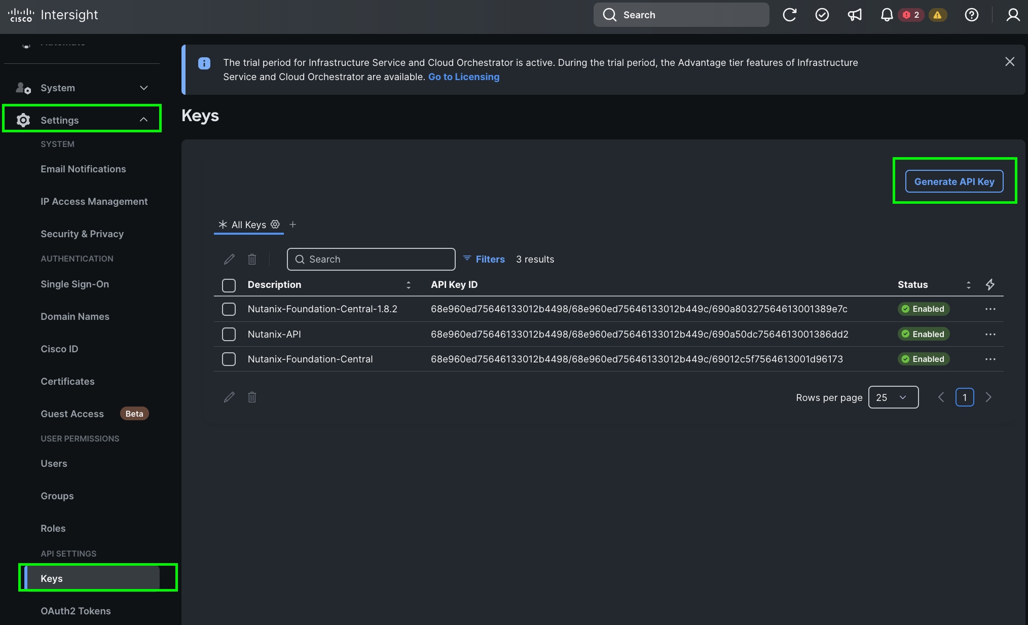
Step 3. Select the API key for OpenAPI schema version 3, add a description and key expiration date and click Generate.
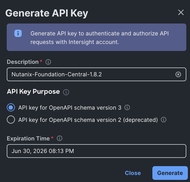
Step 4. Once generated, save the API key ID and Secret Key at a secure place. This will be subsequently added in Nutanix Foundation Central.
Configure Policies for Cisco UCS Domain
The following high-level procedures describe the process to deploy Prism Central either on a Nutanix Cluster or on an ESXi cluster. You should follow either of the procedures for PC installation. Procedure 1 is about deploying Prism Central on Nutanix Cluster while procedure 2 is deploying Prism Central on Non-Nutanix ESXi Cluster as explained below.
Procedure 1. Configure Multicast Policy
Step 1. To configure Multicast Policy for a Cisco UCS Domain profile, go to > Configure > Polices > and click Create Policy.
Step 2. For the platform type select UCS Domain and for Policy, select Multicast Policy.
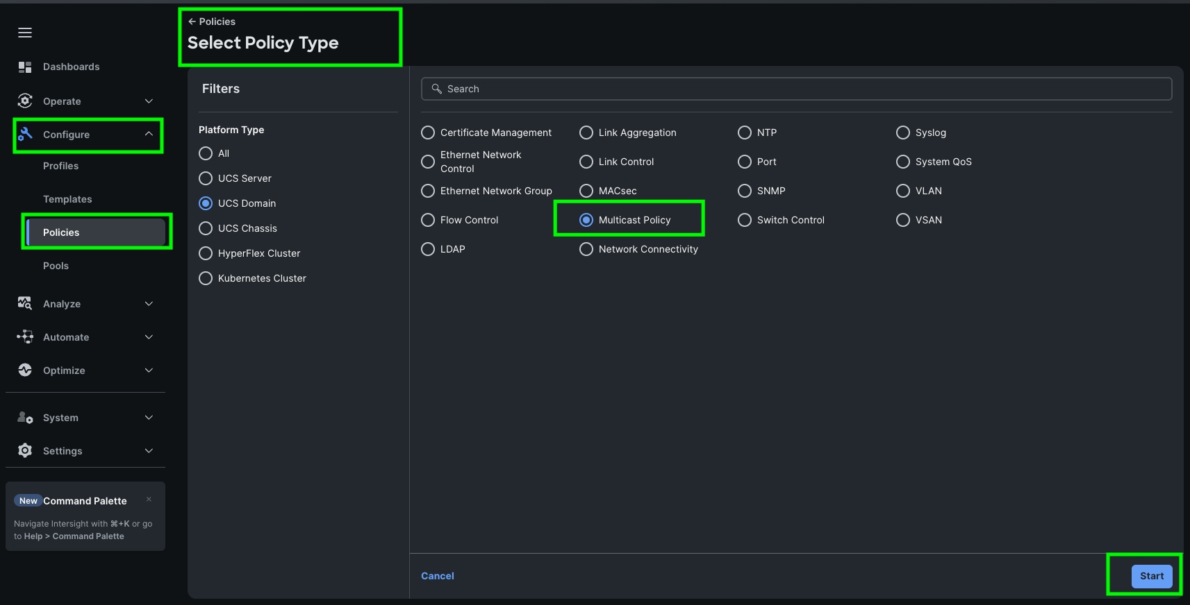
Step 3. In the Multicast Policy Create section, for the Organization select HCI-NTNX-Org and for the Policy name Ntx-Multicast. Click Next.
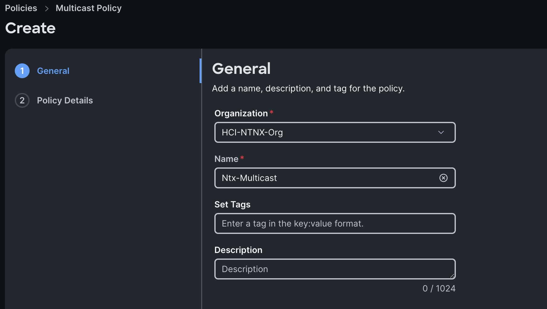
Step 4. In the Policy Details section, select Snooping State and Source IP Proxy State.
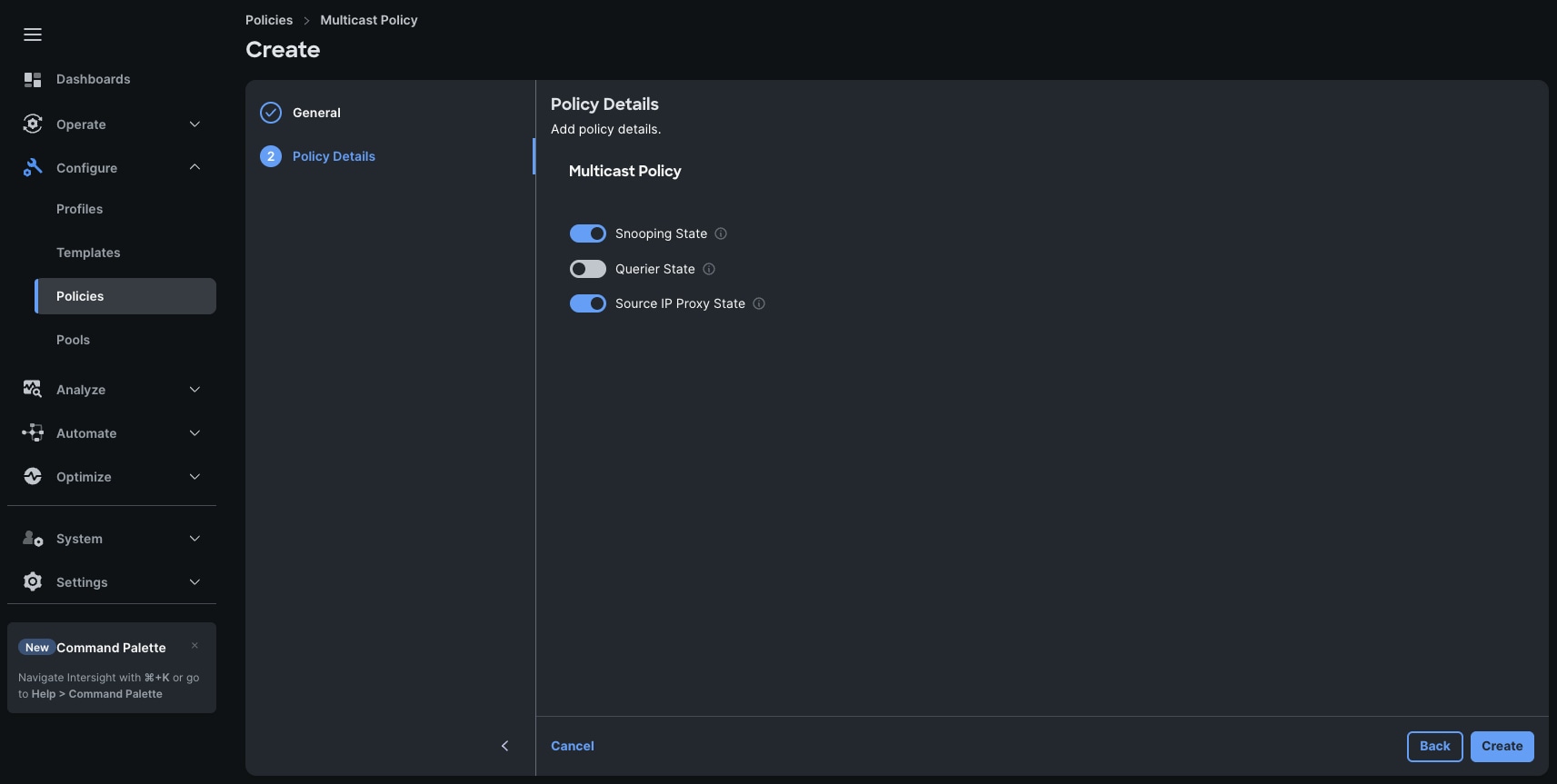
Step 5. Click Create to create this policy.
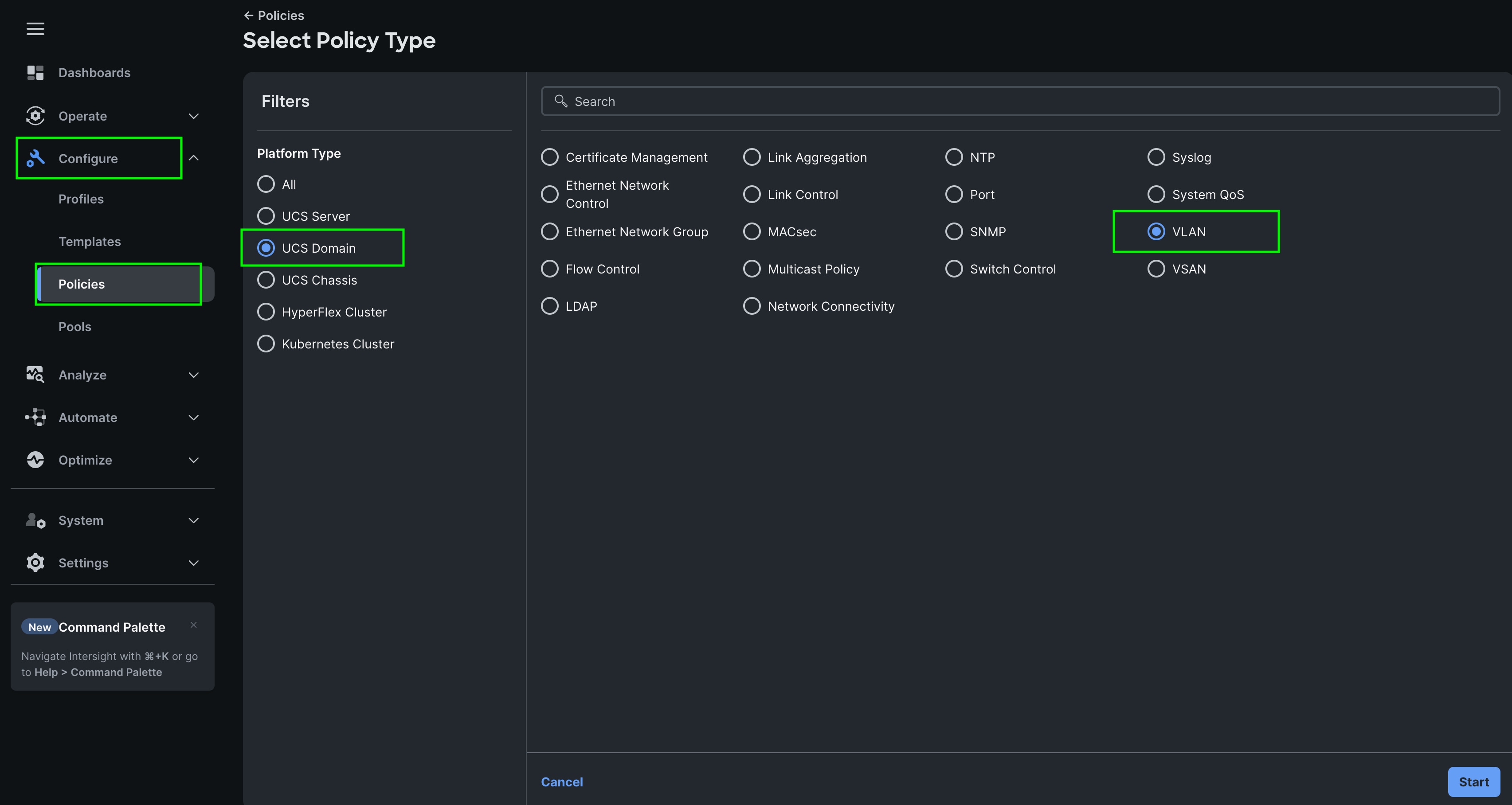
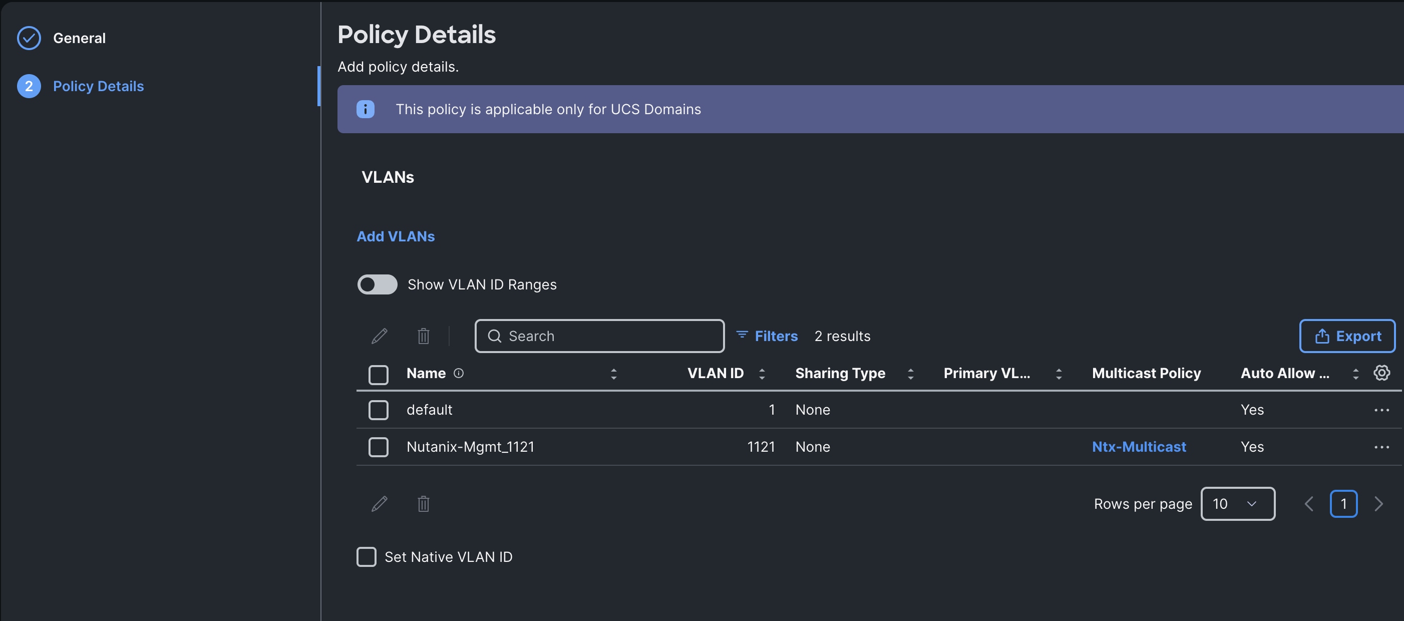
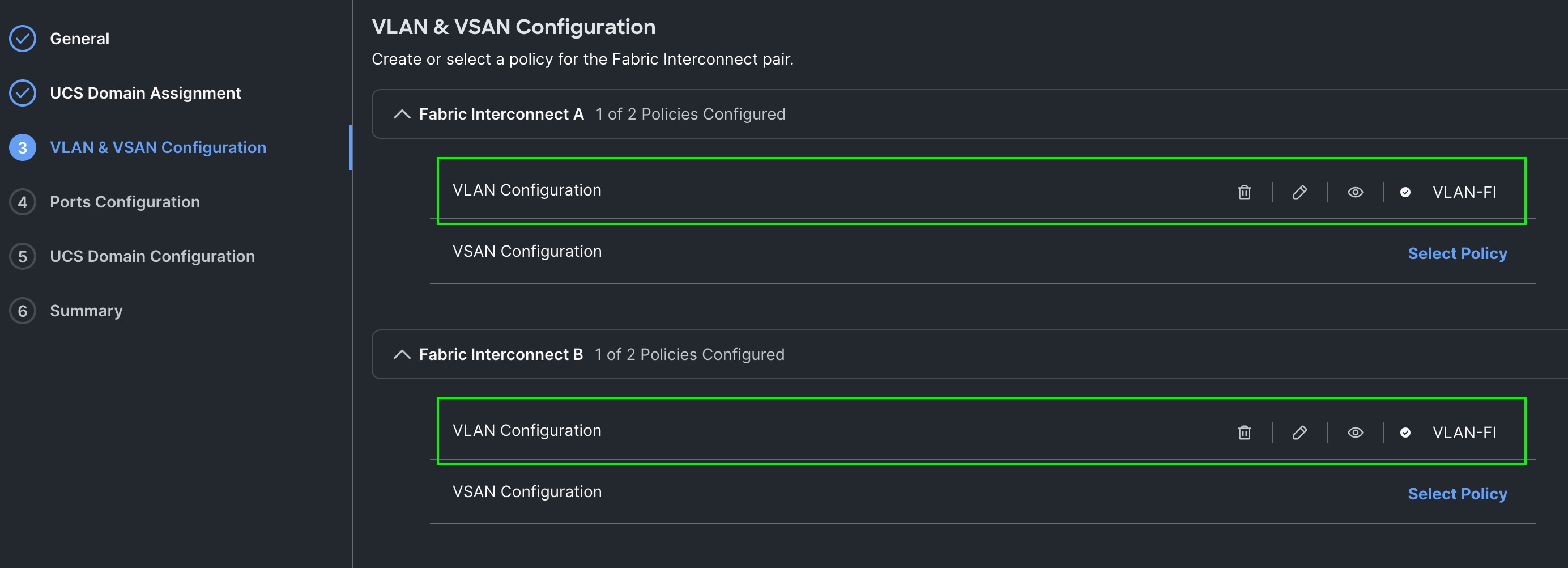
Step 1. To configure the VLAN Policy for the Cisco UCS Domain profile, go to > Configure > Polices > and click Create Policy. For the platform type select UCS Domain and for the Policy select VLAN.
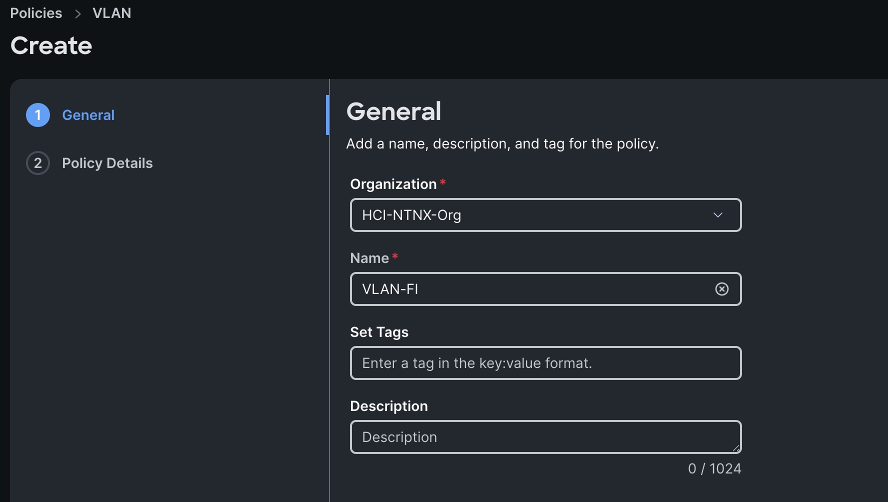
Step 2. In the VLAN Policy Create section, for the Organization select HCI-NTNX-Org and for the Policy name select VLAN-FI. Click Next.
Step 3. In the Policy Details section, to configure the individual VLANs, select Add VLANs.
Step 4. Provide a name, VLAN ID for the VLAN and select the Multicast Policy as shown below:
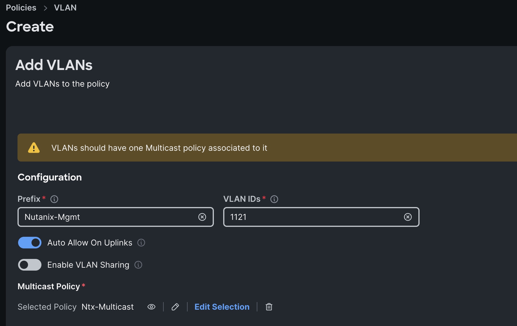
Step 5. Click Add to add this VLAN to the policy.
Step 6. Review the policy details and click Create to create this policy.
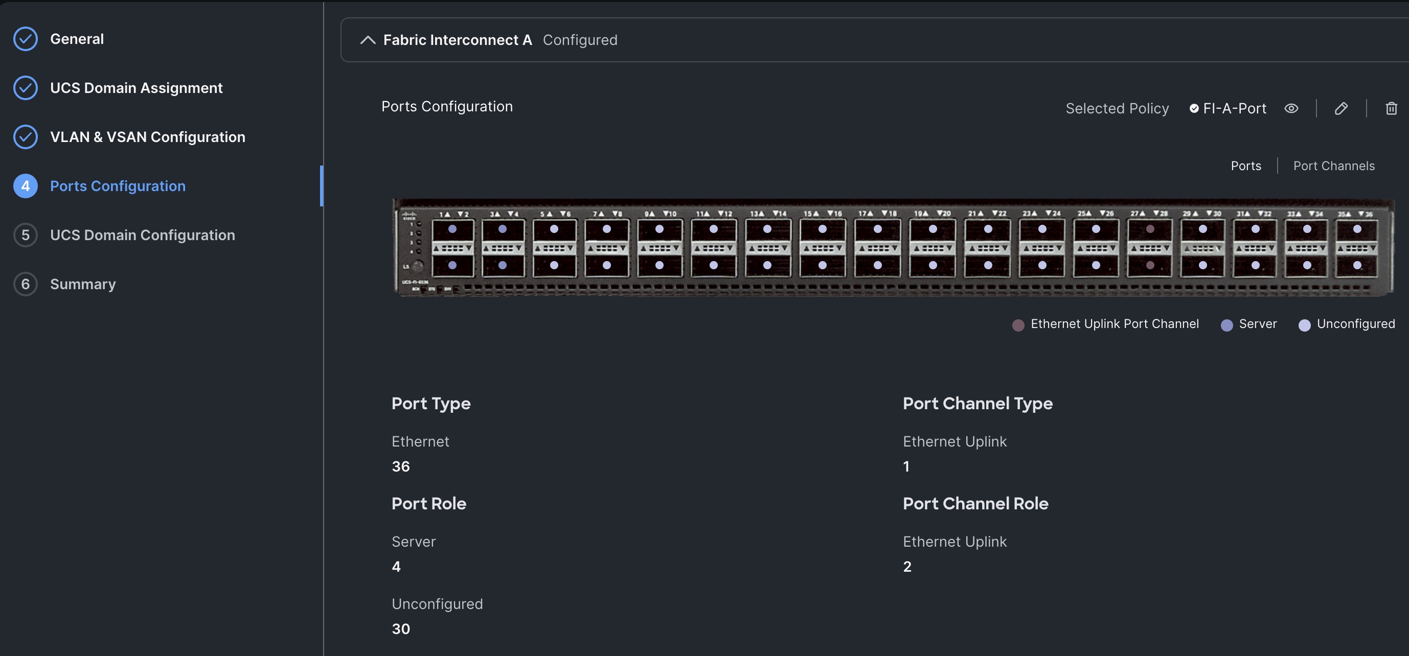
Procedure 3. Configure Port Policy
Step 1. Go to Configure > Polices > and click Create Policy.
Step 2. For the platform type select UCS Domain and for the policy, select Port.
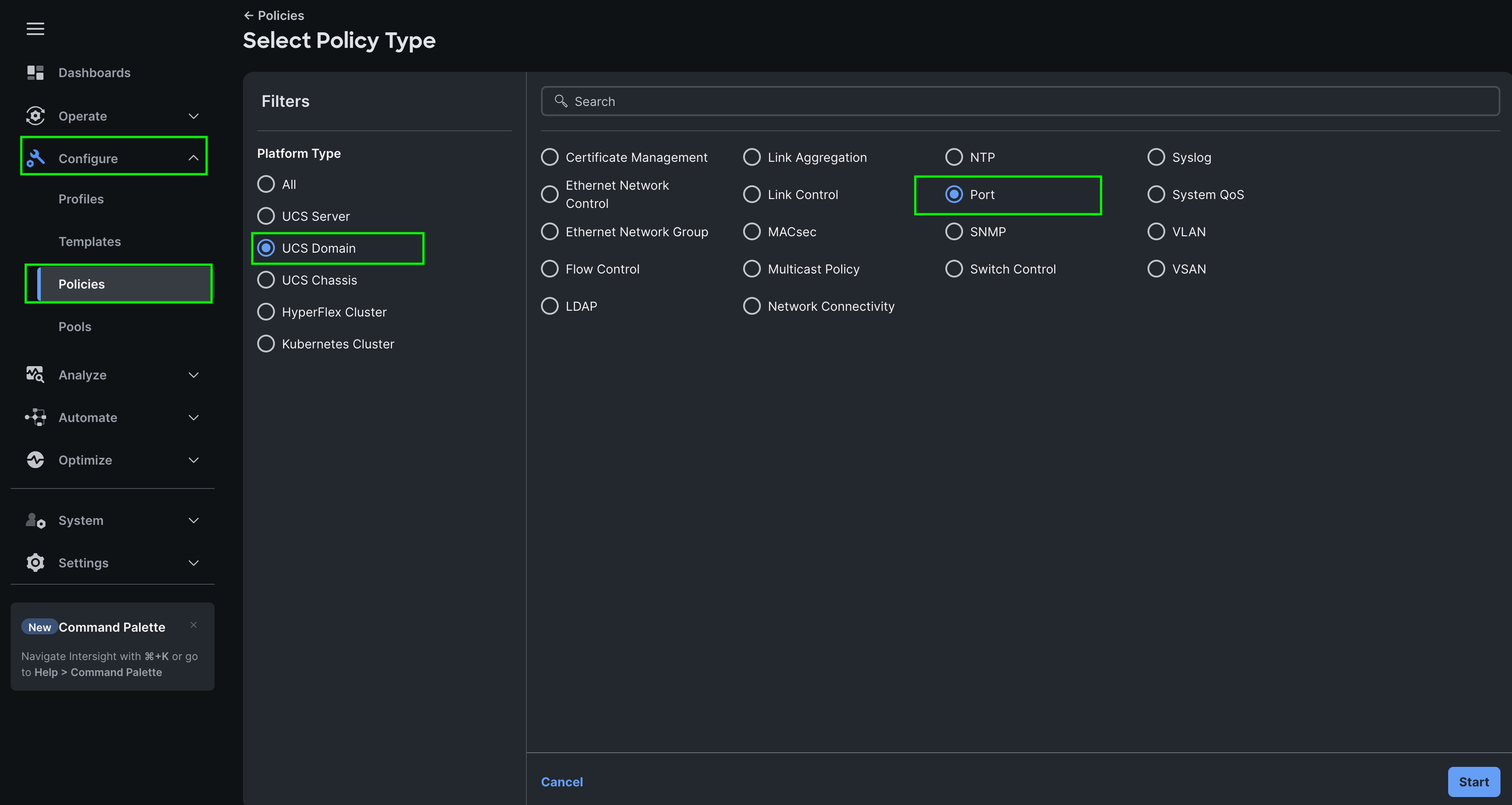
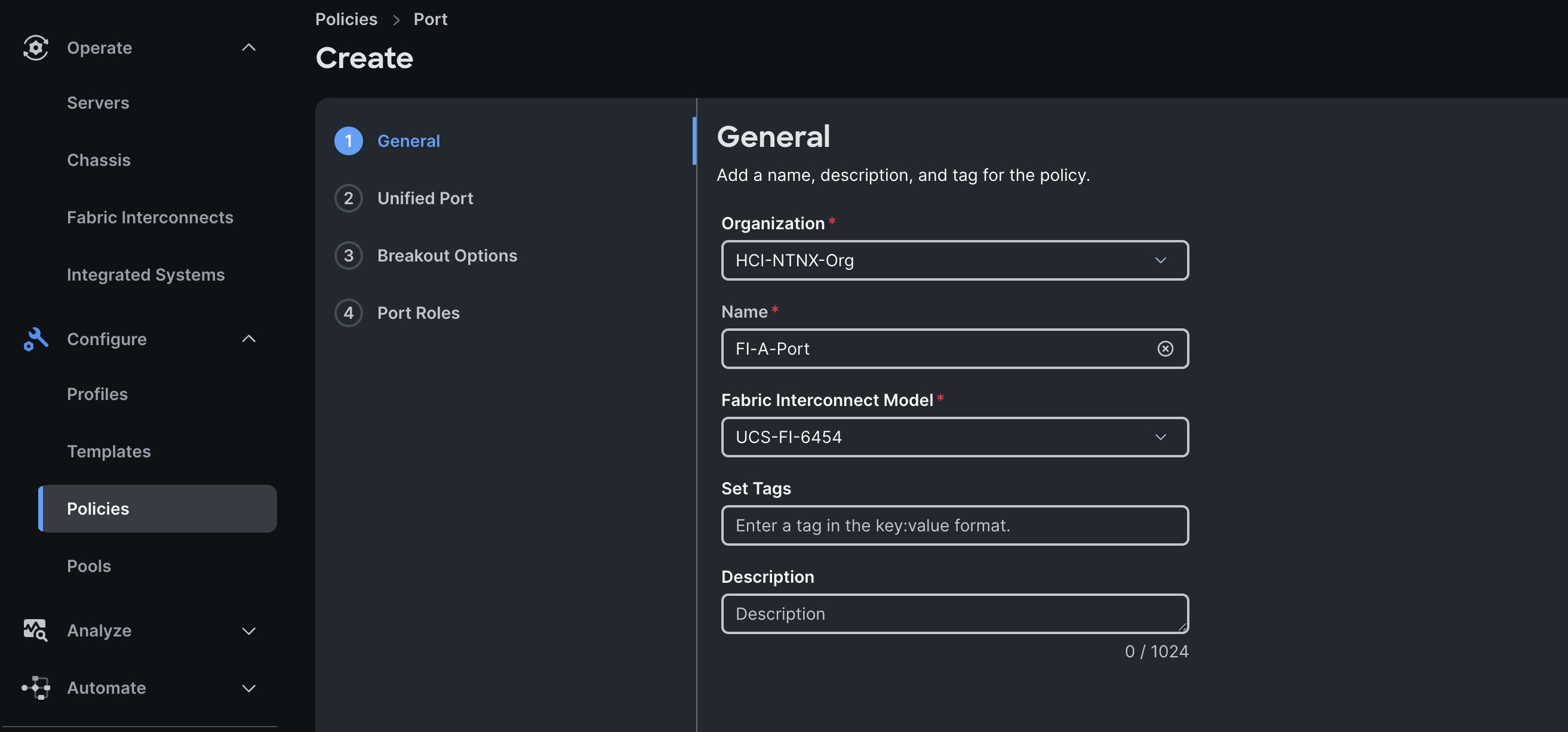
Step 3. In the Port Policy Create section, for the Organization, select HCI-NTNX-Org, for the policy name select FI-A-Port and for the Switch Model select UCS-FI-6536. Click Next.
Note: We did not configure the Fibre Channel Ports for this solution. In the Unified Port section, leave it as default and click Next.
Note: We did not configure the Breakout options for this solution. Leave it as default and click Next.
Step 4. In the Port Role section, select port 1 to 4 and click Configure.
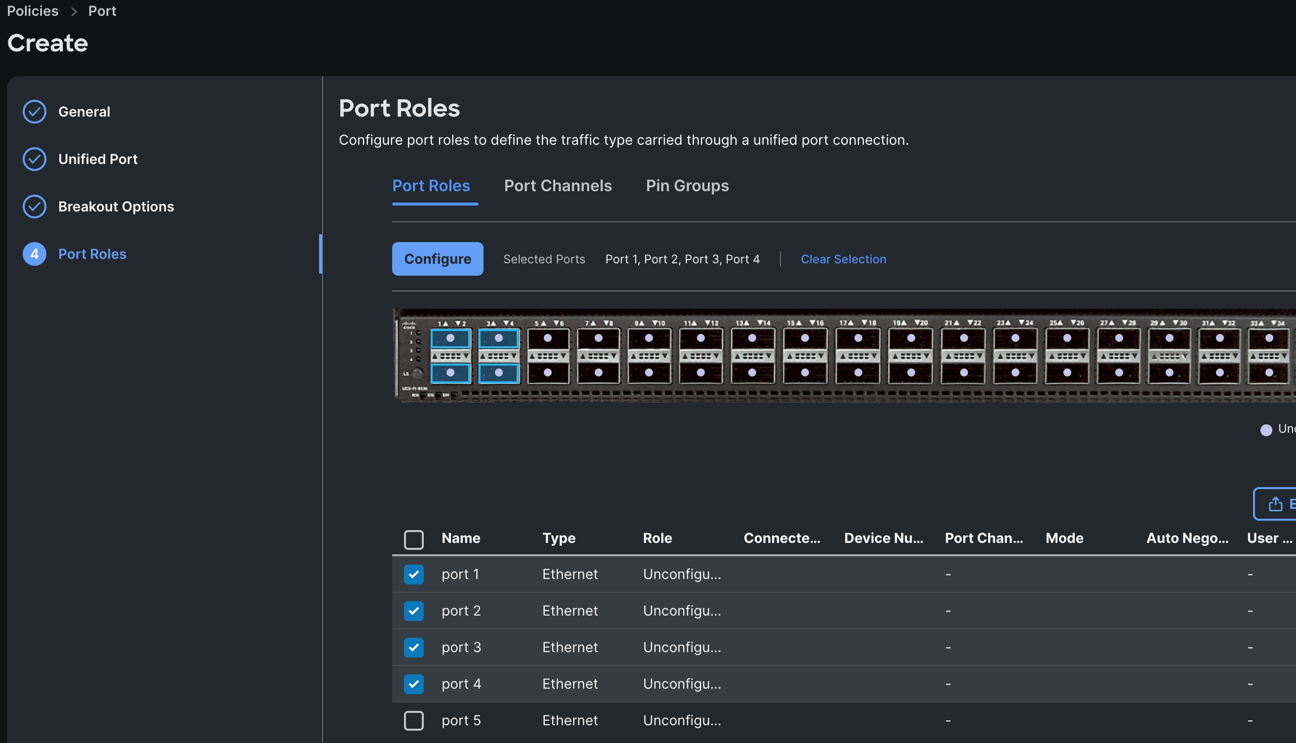
Step 5. In the Configure section, for Role select Server and keep the Auto Negotiation ON, keep Manual Server Numbering as disable.
Step 6. Click SAVE to add this configuration for port roles.
Step 7. Go to the Port Channels tab and select Port 27 to 28 and click Create Port Channel between FI-A and both Cisco Nexus Switches.
Step 8. In the Create Port Channel section, for Role select Ethernet Uplinks Port Channel, and for the Port Channel ID select 51 and select Auto for the Admin Speed.
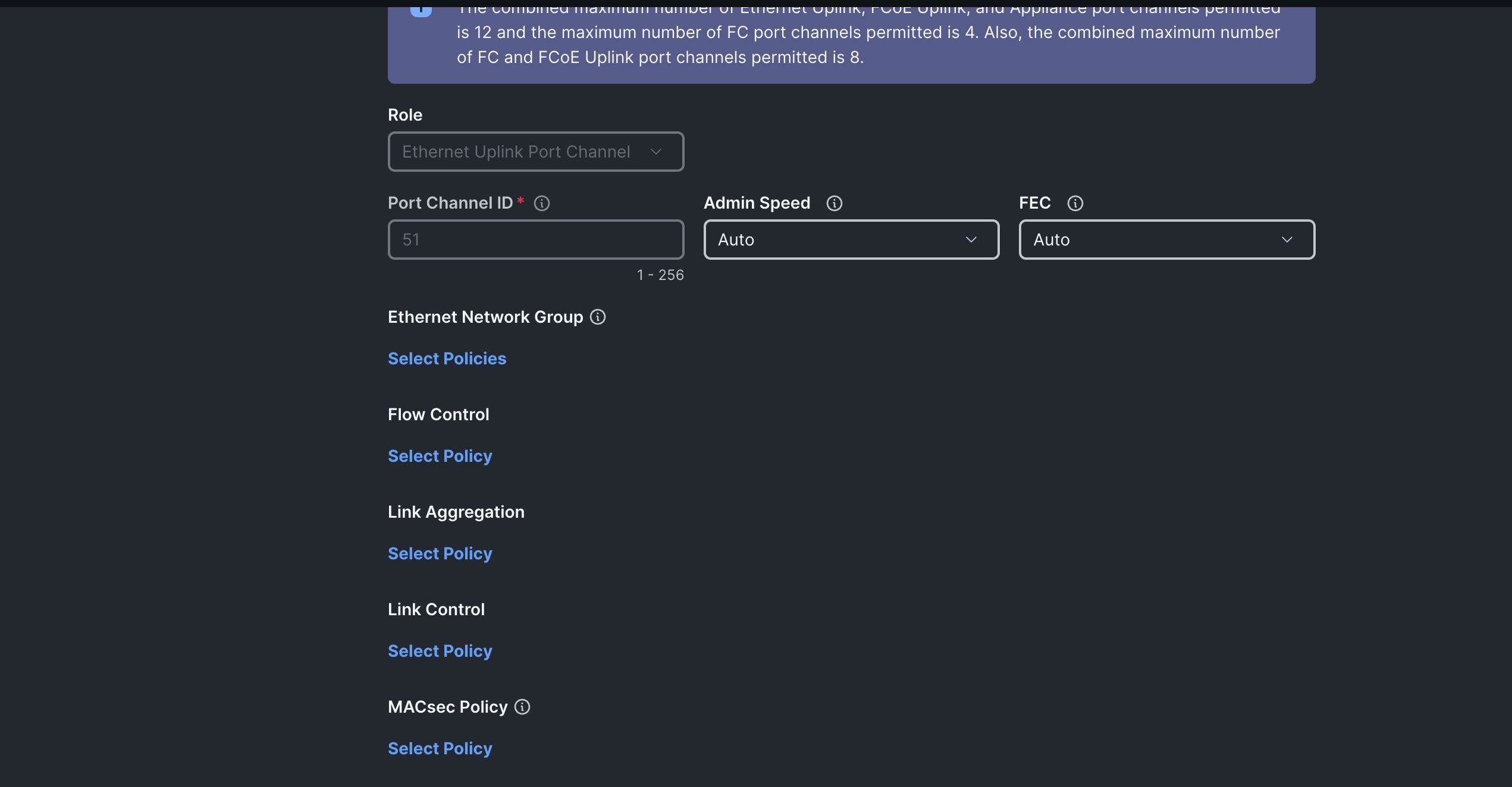
Step 9. Click SAVE to add this configuration for uplink port roles.
Step 10. Click SAVE to complete this configuration for all the server ports and uplink port roles.
Note: We configured the FI-B ports and created a Port Policy for FI-B, “FI-B-Port.”
Note: As configured for FI-A, we configured the port policy for FI-B. For FI-B, configured port 1 to 4 for server ports and ports 27 to 28 as the ethernet uplink port-channel ports.
Note: For FI-B, we configured Port-Channel ID as 52 for Ethernet Uplink Port Channel as shown below:
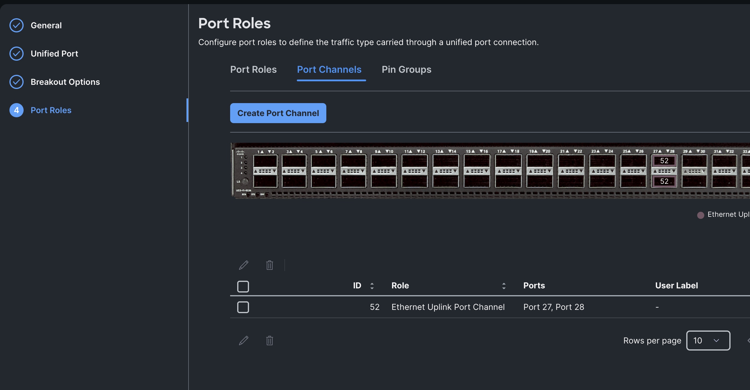
This completes the Port Policy for FI-A and FI-B for Cisco UCS Domain profile.
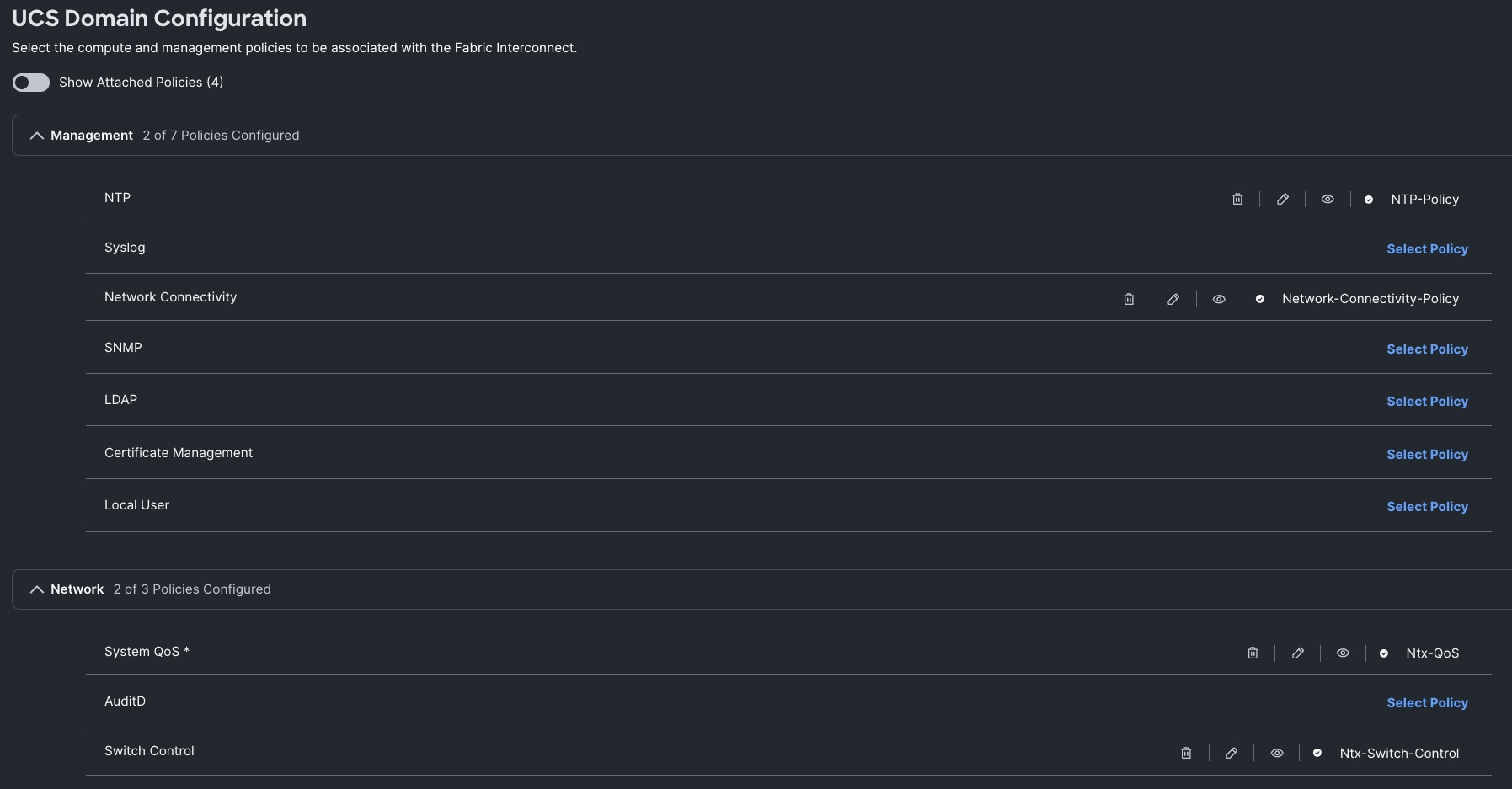
Procedure 4. Configure NTP Policy
Step 1. To configure the NTP Policy for the Cisco UCS Domain profile, go to > Configure > Polices > and click Create Policy. For the platform type select UCS Domain and for the policy select NTP.
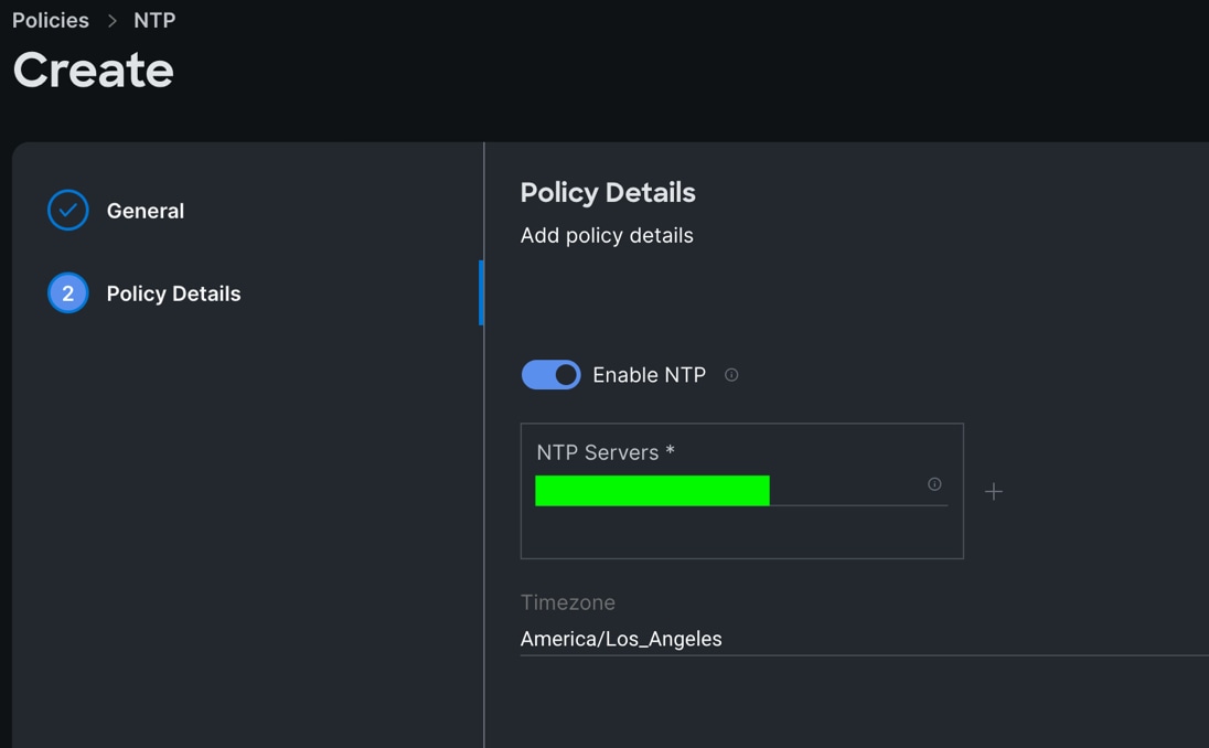
Step 2. In the NTP Policy Create section, for the Organization select HCI-NTNX-Org and for the policy name select NTP-Policy. Click Next.
Step 3. In the Policy Details section, select the option to enable the NTP Server and enter your NTP Server details as shown below:
Step 4. Click Create.
Procedure 5. Configure Network Connectivity Policy
Step 1. To configure to Network Connectivity Policy for the Cisco UCS Domain profile, go to > Configure > Polices > and click Create Policy. For the platform type select UCS Domain and for the policy select Network Connectivity.
Step 2. In the Network Connectivity Policy Create section, for the Organization select HCI-NTNX-Org and for the policy name select Network-Connectivity-Policy. Click Next.
Step 3. In the Policy Details section, enter the IPv4 DNS Server information according to your environment details as shown below:
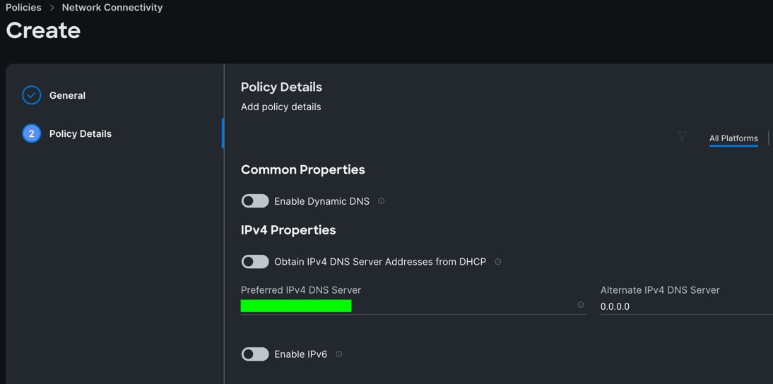
Step 4. Click Create.
Procedure 6. Configure System QoS Policy
Step 1. To configure the System QoS Policy for the Cisco UCS Domain profile, go to > Infrastructure Service > Configure > Polices > and click Create Policy. For the platform type select UCS Domain and for the policy select System QoS.
Step 2. In the System QoS Policy Create section, for the Organization select HCI-NTNX-Org and for the policy name select Ntx-QoS. Click Next.
Step 3. In the Policy Details section under Configure Priorities, select Best Effort and set the MTU size to 9216.
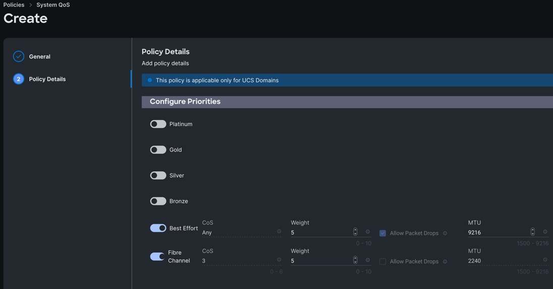
Step 4. Click Create.
Procedure 7. Configure Switch Control Policy
Step 1. To configure the Switch Control Policy for the UCS Domain profile, go to > Infrastructure Service > Configure > Polices > and click Create Policy. For the platform type select UCS Domain and for the policy select Switch Control.
Step 2. In the Switch Control Policy Create section, for the Organization select HCI-NTNX-Org and for the policy name select Ntx-Switch-Control. Click Next.
Step 3. In the Policy Details section, keep all the option default as shown below:
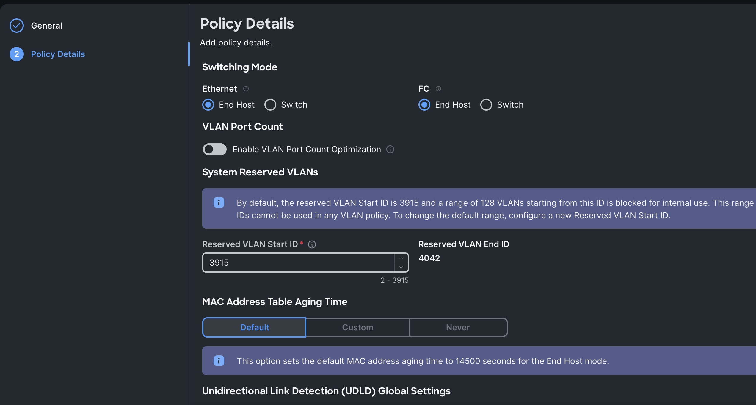
Step 4. Click Create to create this policy.
Configure Cisco UCS Domain Profile
A Domain Profile must be created and deployed to the Fabric Interconnects. The Domain Profile defines the roles of the ports on the Fabric Interconnects, the VLANs used on the network and several other domain-wide policy settings such as QoS. After the Domain Profile is deployed the rackmount servers and/or modular blades will discover and can then be onboarded in Foundation Central and targeted for a Nutanix cluster deployment. Ensure that the profile and all the associated policies are created in the Organization that also contains the Resource Group for the Fabric Interconnects and servers.
For more information, go to: https://intersight.com/help/saas/features/fabric_interconnects/configure#domain_profile
Some of the characteristics of the Cisco UCS domain profile are:
· A single domain profile (HCI-NTNX-Domain) is created for the pair of Cisco UCS fabric interconnects.
· Unique port policies are defined for the two fabric interconnects.
· The VLAN configuration policy is common to the fabric interconnect pair because both fabric interconnects are configured for the same set of VLANs.
· The Network Time Protocol (NTP), network connectivity, and system Quality-of-Service (QoS) policies are common to the fabric interconnect pair.
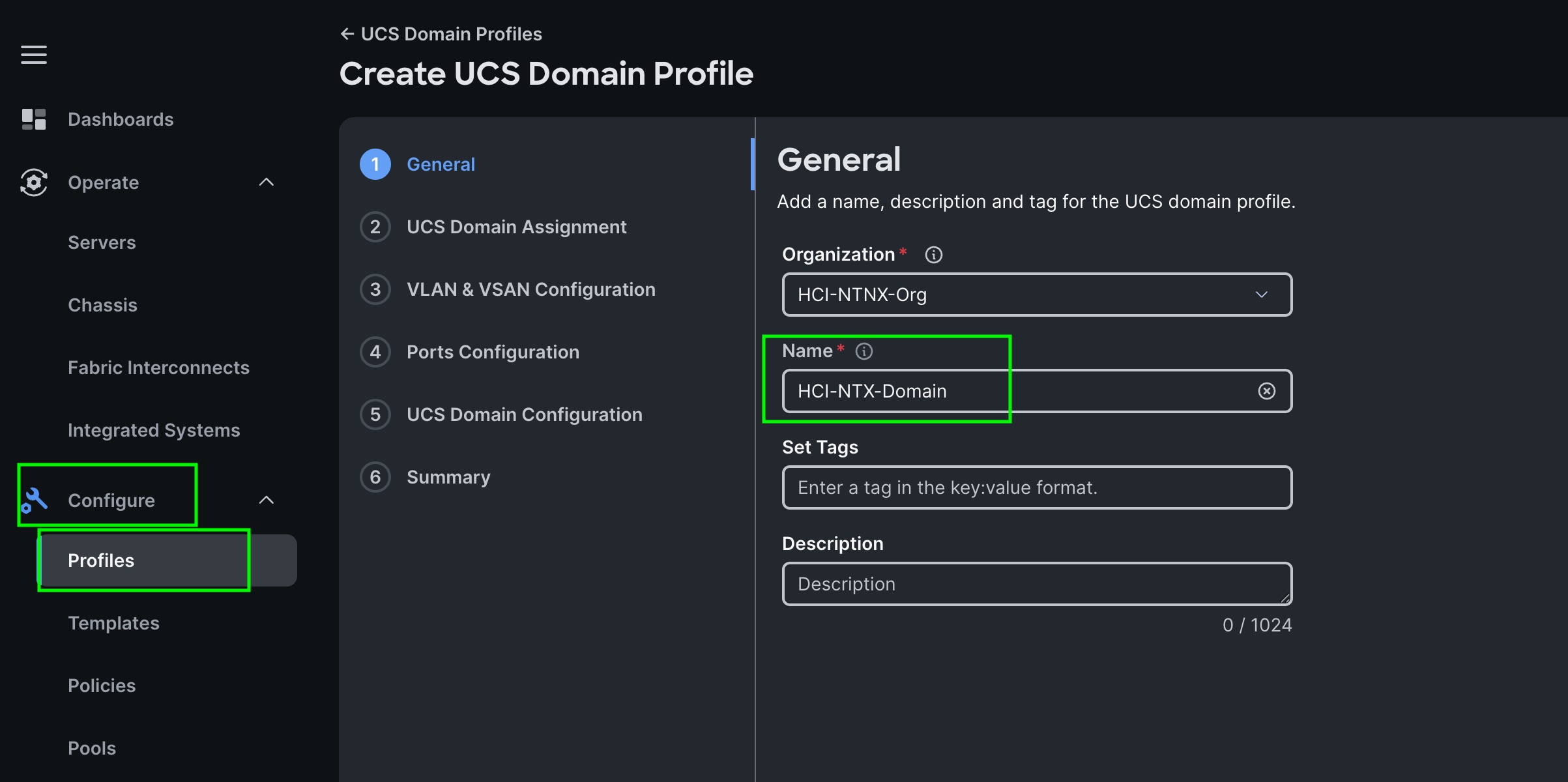
Procedure 1. Create UCS Domain Profile
Step 1. To create a domain profile, go to Configure > Profiles > then go to the UCS Domain Profiles tab and click Create UCS Domain Profile
Step 2. For the domain profile name, enter HCI-NTNX-Domain and for the Organization select what was previously configured. Click Next.
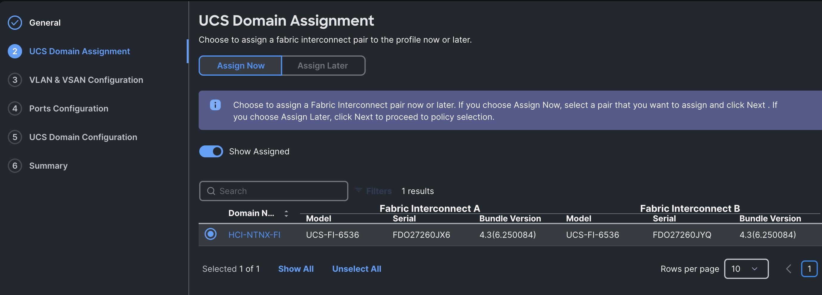
Step 3. In the UCS Domain Assignment menu, for the Domain Name select HCI-NTNXC-FI which was previously added into this domain and click Next.
Step 4. In the VLAN Configuration screen, for the VLAN Configuration for both FIs, select VLAN-FI and click Next.
Step 5. In the Port Configuration section, for the Port Configuration Policy for FI-A select FI-A-Port.
Step 6. For the port configuration policy for FI-B select FI-B-Port .
Step 7. In the UCS Domain Configuration section, select the policy for NTP, Network Connectivity, System QoS and Switch Control as shown below:
Step 8. In the Summary window, review the policies and click Deploy to create Domain Profile.
Note: After the Cisco UCS domain profile has been successfully created and deployed, the policies including the port policies are pushed to the Cisco UCS fabric interconnects. The Cisco UCS domain profile can easily be cloned to install additional Cisco UCS systems. When cloning the Cisco UCS domain profile, the new Cisco UCS domains utilize the existing policies for the consistent deployment of additional Cisco UCS systems at scale.
Step 9. The Cisco UCSX-215C-M8 Compute Nodes are automatically discovered when the ports are successfully configured using the domain profile as shown below. You can check the status of this discovery by clicking Request next to the Refresh page option.
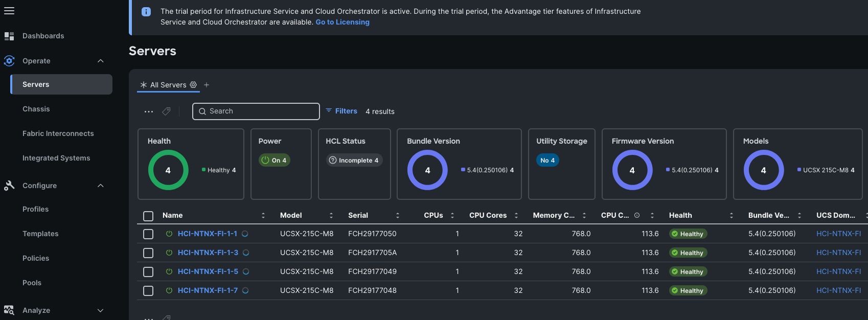
After discovering the servers successfully, you will find all the servers as shown below:
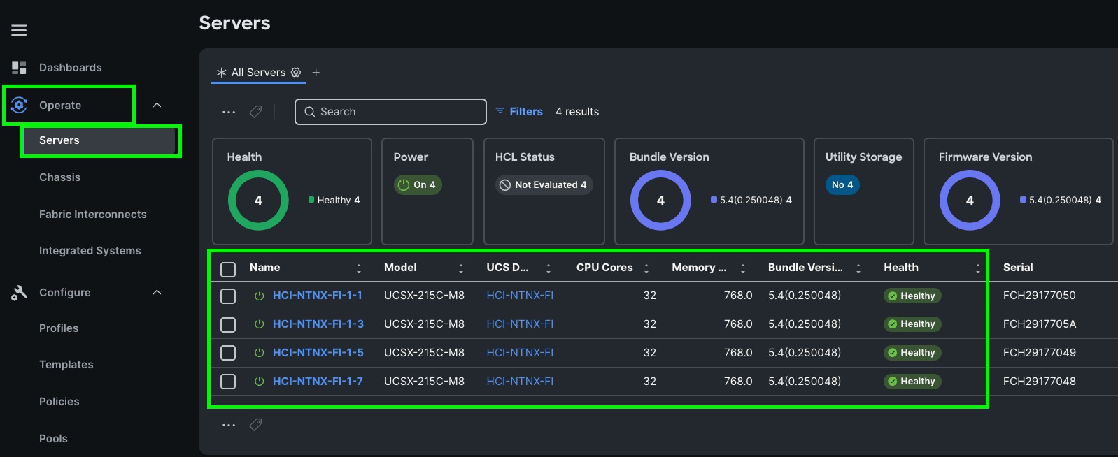
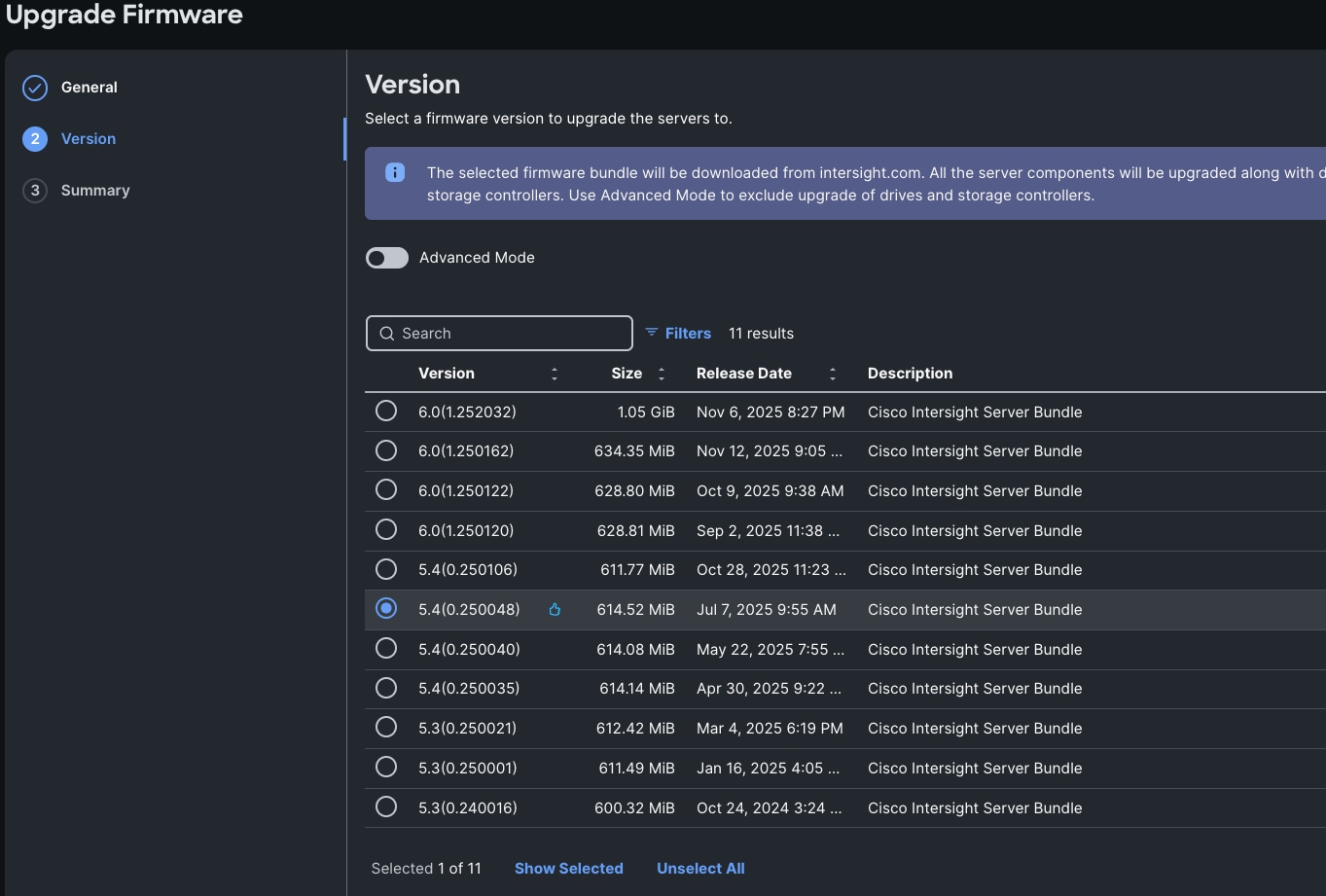
Step 10. After discovering the servers successfully, upgrade all server firmware through IMM to the supported release. To do this, check the box for All Servers and then click the ellipses and from the drop-down list, select Upgrade Firmware.
Step 11. In the Upgrade Firmware section, select all servers and click Next. In the Version section, for the supported firmware version release select 5.4 (0.250048) and click Next, then click Upgrade to upgrade the firmware on all servers simultaneously.
Step 12. After the successful firmware upgrade, you are now ready to configure nutanix cluster configuration.
Prior to beginning the installation of Nutanix Cluster on Cisco UCS X-Series servers in IMM, you should ensure you have deployed Nutanix Prism Central and enabled Nutanix Foundation Central through Nutanix marketplace available through Prism Central. Foundation Central can create clusters from factory-imaged nodes and reimage existing nodes that are already registered with Foundation Central from Prism Central. This provides benefits such as creating and deploying several clusters on remote sites, such as ROBO, without requiring onsite visits.
To continue with the deployment of Nutanix on Cisco UCS X-Series servers in Intersight Managed Mode (IMM), ensure the following:
· Cisco Intersight SaaS account, or the connected or private virtual appliance with sufficient licenses
· Prism Central is deployed on either a Nutanix Cluster or on ESXi cluster
· Foundation Central is enabled on Prism Central and upgrade it to the latest version 1.8.2
· A local webserver is available hosting Nutanix AHV and AOS images such as the Cisco IMM toolkit VM
· NTP sync and DNS name resolution for Cisco Intersight or the Intersight appliance, and Prism Central
Note: For this solution, we used non-Nutanix ESXi Prism Central 2022.6.0.12 for only as a temporary single VM for Foundation Central to install the initial cluster. Cisco recommends that an installation of Prism Central on a non-Nutanix ESXi platform is only used temporarily to install the first Nutanix clusters, and long-term the best solution is to deploy Prism Central on a Nutanix cluster.
Note: If desired, Prism Central version 2024.3.x or 7.3.x can be deployed as an OVA on a non-Nutanix ESXi infrastructure platform instead of Prism Central version 2022.6, however the process to do so has additional requirements and is a more difficult installation process. When deploying Prism Central in a non-Nutanix environment, ensure that you use the necessary ESXi administrator credentials to install or upgrade a Prism Central instance in a non-Nutanix ESXi environment. For more information please refer as: https://portal.nutanix.com/page/documents/details?targetId=Prism-Central-Guide:mul-install-prism-central-non-nutanix-c.html
The following high-level procedures describe the process to deploy Prism Central either on a Nutanix Cluster or on an ESXi cluster. You should follow either of the procedures for PC installation. Procedure 1 is about deploying Prism Central on Nutanix Cluster while procedure 2 is deploying Prism Central on Non-Nutanix ESXi Cluster as explained below.
Procedure 1. Deploy PC 7.3.1.1 on Nutanix Cluster
Note: Skip this step if you already have PC 7.3.1.1
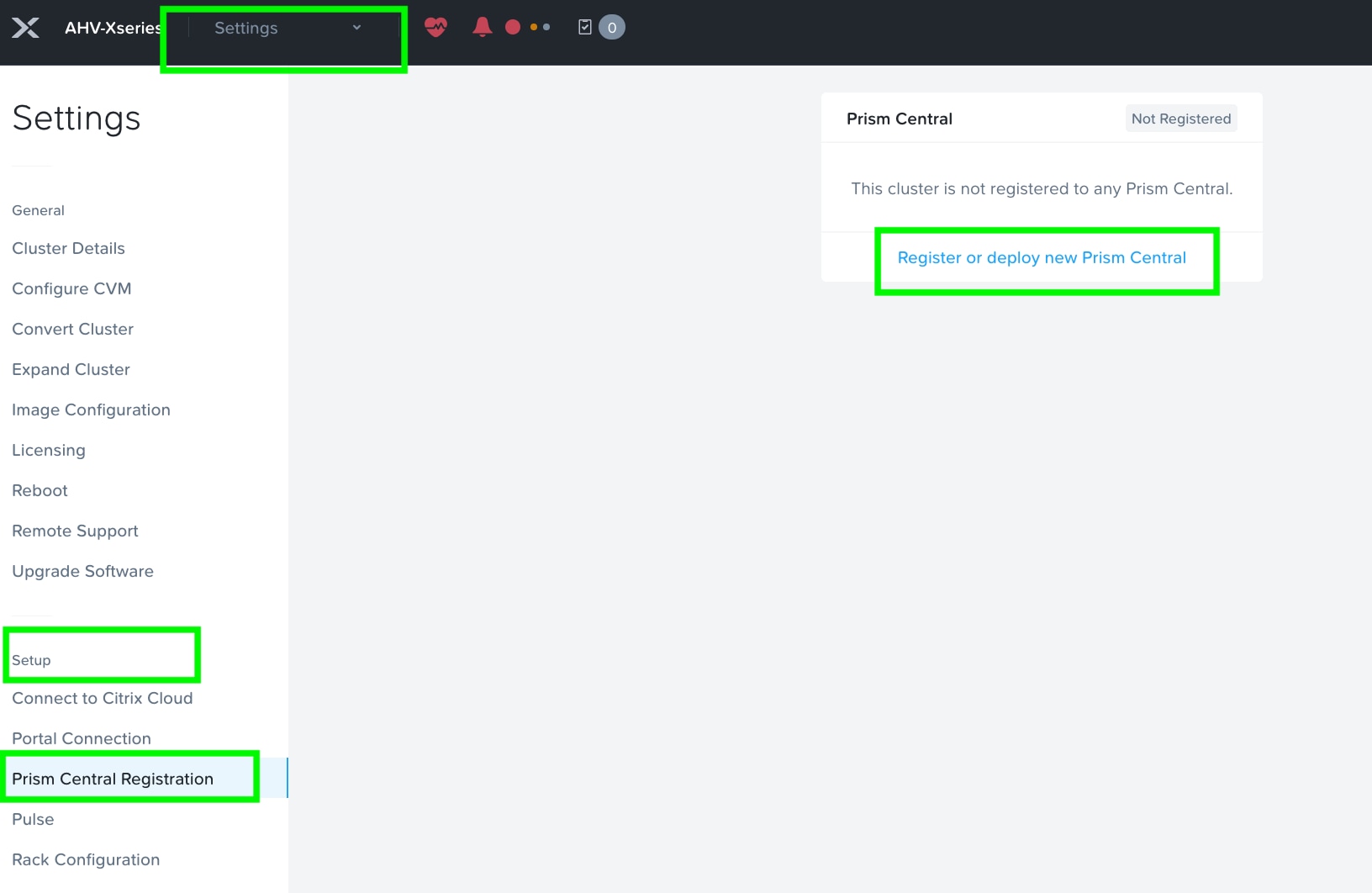
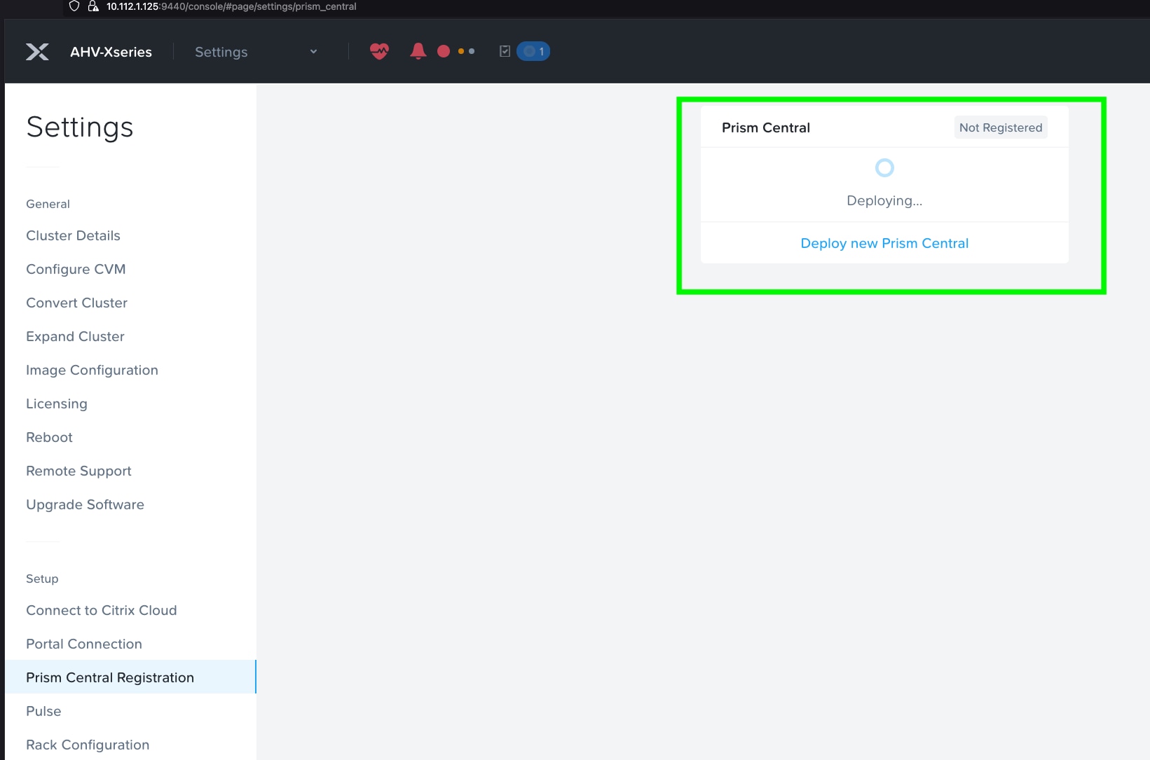
Step 1. Log into Prism Element on Nutanix Cluster and navigate to Settings > Prism Central Registration.
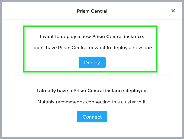
Step 2. Select the option Register or deploy new Prism Central.
Step 3. Click Deploy, as shown below, to deploy a new Prism Central Instance:
Step 4. Prism Central binaries are available here: https://portal.nutanix.com/page/downloads?product=prism
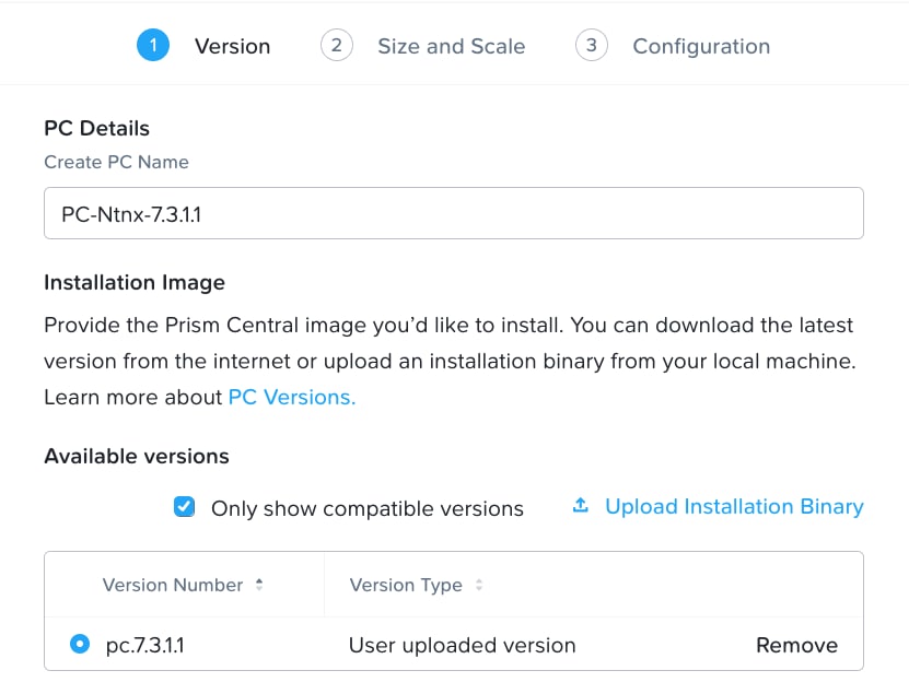
Step 5. Download Prism Central Metadata File (.json) and Prism Central Installation Binary (.tar) installation binary for the supported version 7.3.1.1 and upload it by clicking the option Upload Installation Binary.
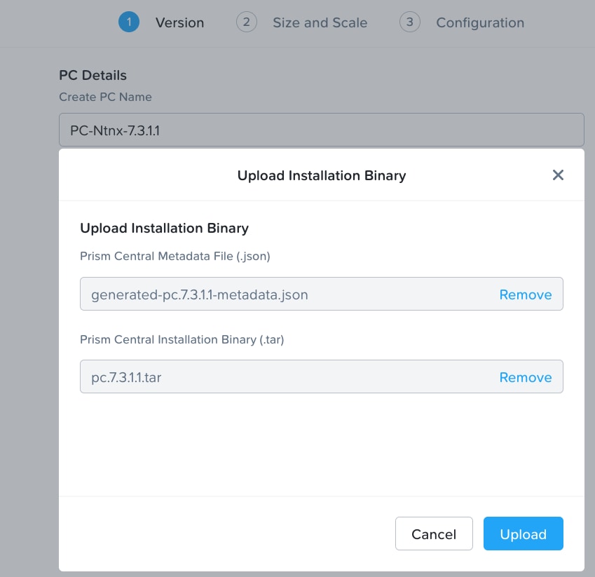
Note: For this solution, we deployed Prism Central version 7.3.1.1 as shown below.
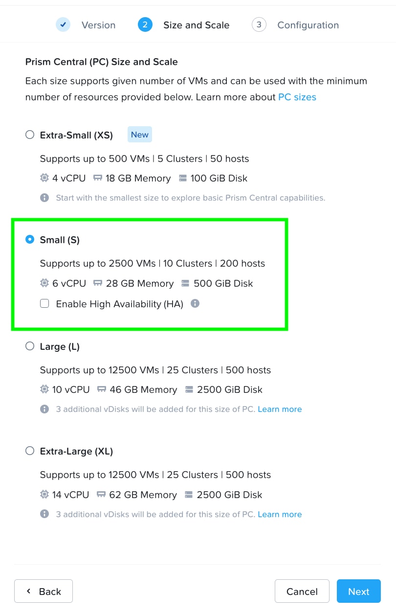
Step 6. Select the appropriate Prism Central deployment option as per your resiliency requirement.
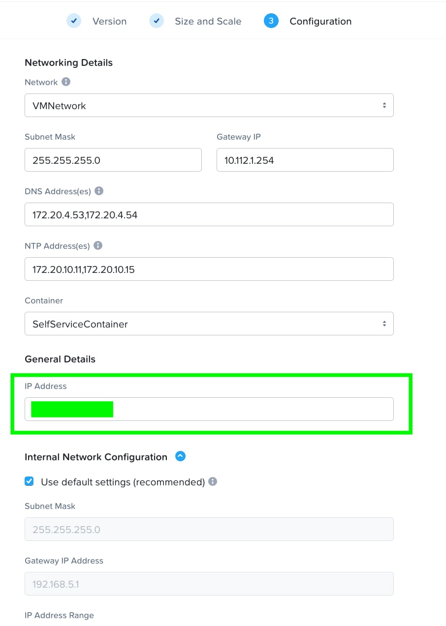
Step 7. Enter valid networking details and IP addressing for Prism Central. Even though DNS is optional, ensure a valid DNS is defined for successful discovery of Cisco Intersight domain name.
Step 8. Click Deploy to create and deploy Prism Central on Nutanix Cluster.
Procedure 2. Deploy PC 2022.6.x on ESXi Cluster
Note: Skip this step if you already have a Prism Central Instance configured from Procedure 1.
Step 1. Download Prism Central 2022.6.12 OVA here: https://portal.nutanix.com/page/downloads?product=prism
Step 2. Identify an ESXi host and deploy OVF template.
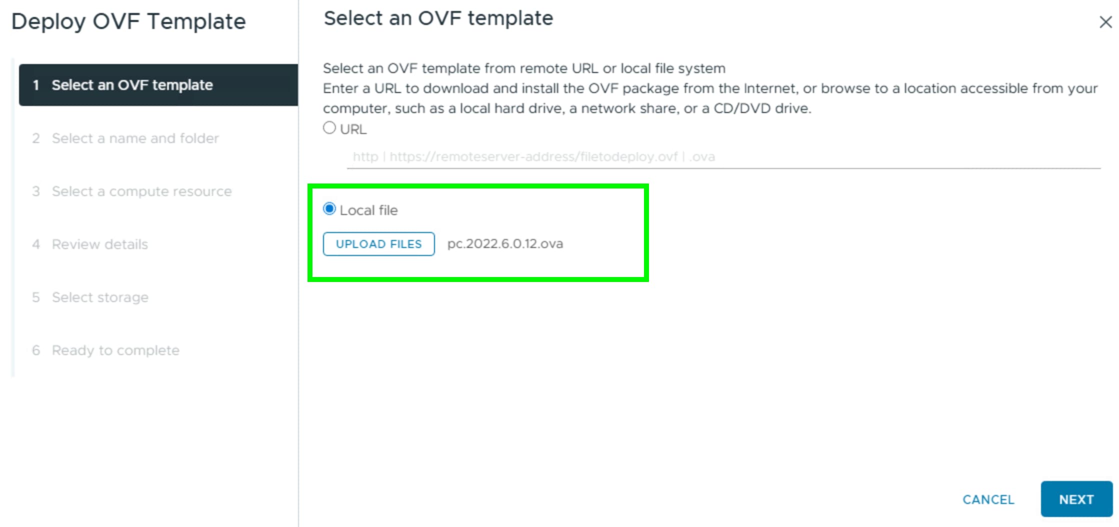
Step 3. Identify compute, storage, and network resource on ESXi Cluster and deploy the OVF template.
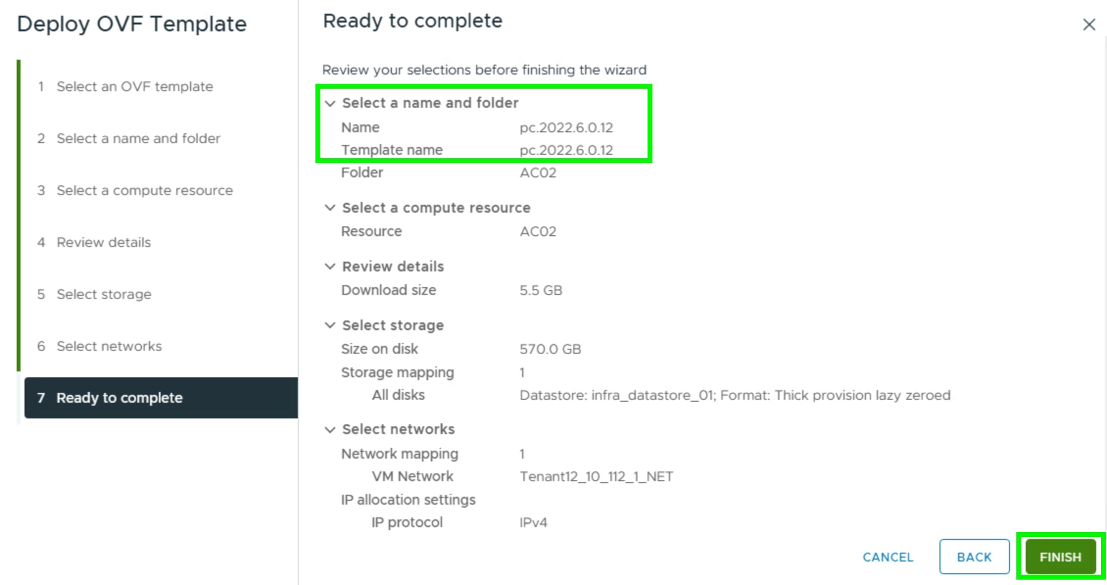
Step 4. When the OVA is deployed, power ON the VM.
Note: Post installation steps for Prism Central on ESXi are detailed here: https://portal.nutanix.com/page/documents/details?targetId=Prism-Central-Guide-vpc_7_3:upg-vm-install-wc-t.html
Step 5. Wait at least 20-25 minutes before you log into PC instance through ESXi web console.
Step 6. Open the vSphere/ESXi web interface and connect to the Prism Central VM’s console. Use the default credentials to log in as user Nutanix and password nutanix/4u.
Step 7. Assign a static IP address, subnet mask, gateway to the Prism Central VM.
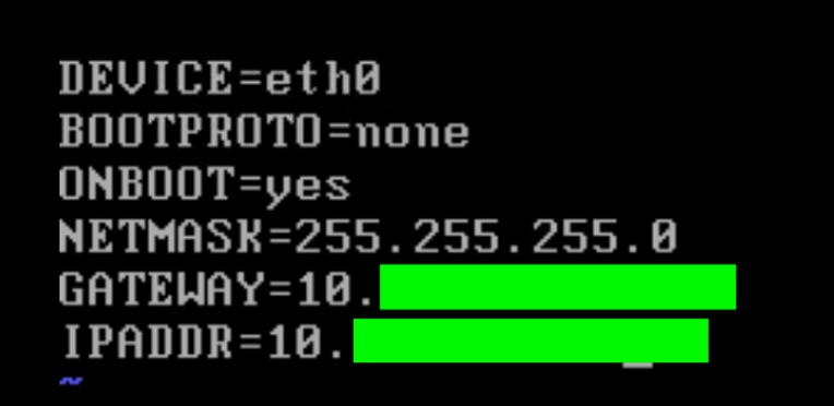
Step 8. Edit the ifcfg-eth0 with the following settings (sudo vi /etc/sysconfig/network-scripts/ifcfg-eth0):
- NETMASK="xxx.xxx.xxx.xxx"
- IPADDR="xxx.xxx.xxx.xxx"
- BOOTPROTO="none"
- GATEWAY="xxx.xxx.xxx.xxx"
Step 9. Confirm and save changes.
Step 10. Edit the /etc/hosts file to remove all lines containing any entry like 127.0.0.1 NTNX-10-3-190-99-ACVM:
- $ sudo vi /etc/hosts
- $ sudo reboot
Step 11. After completing above steps, reboot the VM to apply the updated network configuration.
Step 12. Wait for the “nutanix-rc-local” service to complete, confirming services (such as Genesis) are running.
Step 13. Log into the Prism Central VM using SSH as user: nutanix and password: nutanix/4u
Step 14. Run the command to create the Prism Central cluster:
$ cluster --cluster_function_list "multicluster" -s <static_ip_address> --dns_servers "<DNS 1 IP>,<DNS 2 IP>" --ntp_servers "<NTP 1 IP>,<NTP 2 IP>" create
Step 15. Log into the Prism Central VM GUI with a web browser at https://<static_ip_address>:9440 as user: “admin” & password: “nutanix/4u”
Step 16. When completed, log into Prism Central 2022.6.x.
This section provides the procedures to enable and upgrade Foundation Central on Prism Central 2022.6.x.
Procedure 1. Enable and Upgrade Foundation Central (FC) to 1.8.2 on PC 2022.6.x
Note: Upgrade Foundation Central on Prism Central via CLI as explained below.
Note: Ensure the DNS (name server) and NTP settings are updated in Prism Central.
Step 1. Go to Services > Foundation Central and enable Foundation Central.
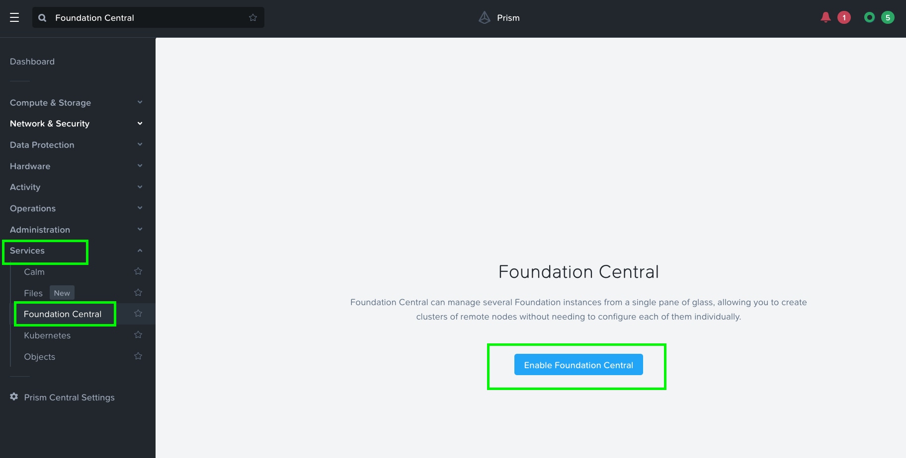
Step 2. After enabling Foundation Central, upgrade to the latest Foundation Central.
Step 3. Download the latest Foundation Central LCM Bundle (1.8.2) lcm_foundation-central_1.8.2.tar.gz from the Nutanix Downloads page (https://portal.nutanix.com/page/downloads?product=foundationcentral) and copy it to the Prism Central VM at /home/nutanix/.
Step 4. For more information on upgrading FC to 1.8.x, go to: https://portal.nutanix.com/page/documents/details?targetId=Foundation-Central-v1_8:v1-upgrade-fc-cli-t.html
Step 5. SSH into Prism Central VM with the username nutanix.
Step 6. Extract the bundle to a temporary directory:
mkdir /home/nutanix/fc_installer
tar -xf /home/nutanix/lcm_foundation-central_1.8.2.tar.gz -C /home/nutanix/fc_installer/
Step 7. Stop the Foundation Central service if it is running:
genesis stop foundation_central
Step 8. Remove the Foundation Central files if they are present:
sudo rm -rf /home/docker/foundation_central/*
Step 9. Extract the Foundation Central bits to the target location:
sudo tar -xJf /home/nutanix/fc_installer/builds/foundation-central-builds/1.8.2/foundation-central-installer.tar.xz -C /home/docker/foundation_central/
Step 10. Set the directory permission to nutanix:nutanix:
sudo chown -R nutanix:nutanix /home/docker/foundation_central/*
Step 11. Start the Foundation Central service:
cluster start
Step 12. In some cases, you may need to flush your browser cache and reboot the Prism Central server after the manual upgrade.
Step 13. You can validate the service status by running genesis status command on the Prism Central VM.
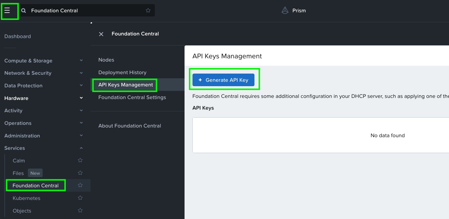
Procedure 2. Generate API Keys in Foundation Central (FC)
Note: Ensure the DNS (name server) and NTP settings are updated in Prism Central.
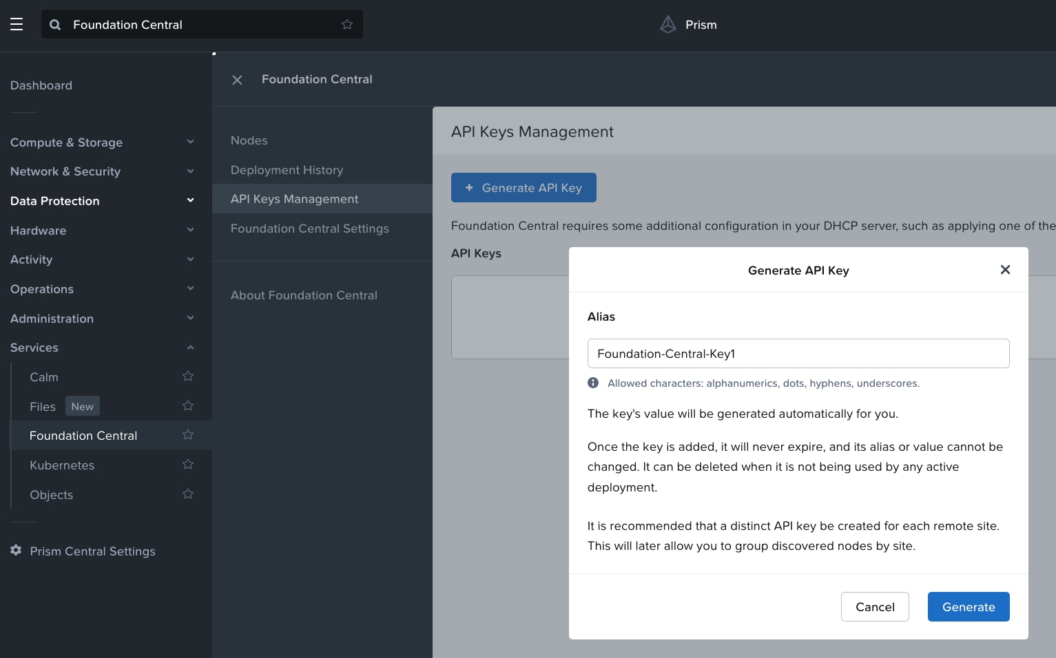
Step 1. In Prism Central, go to Services > Foundation Central > Settings and click Generate API Key.
Step 2. In Generate API Key, enter the name of the Alias name of the key as Foundation-Central-Key1 and click Generate.
The API key displays. It will be added during the Nutanix cluster creation through Foundation Central.
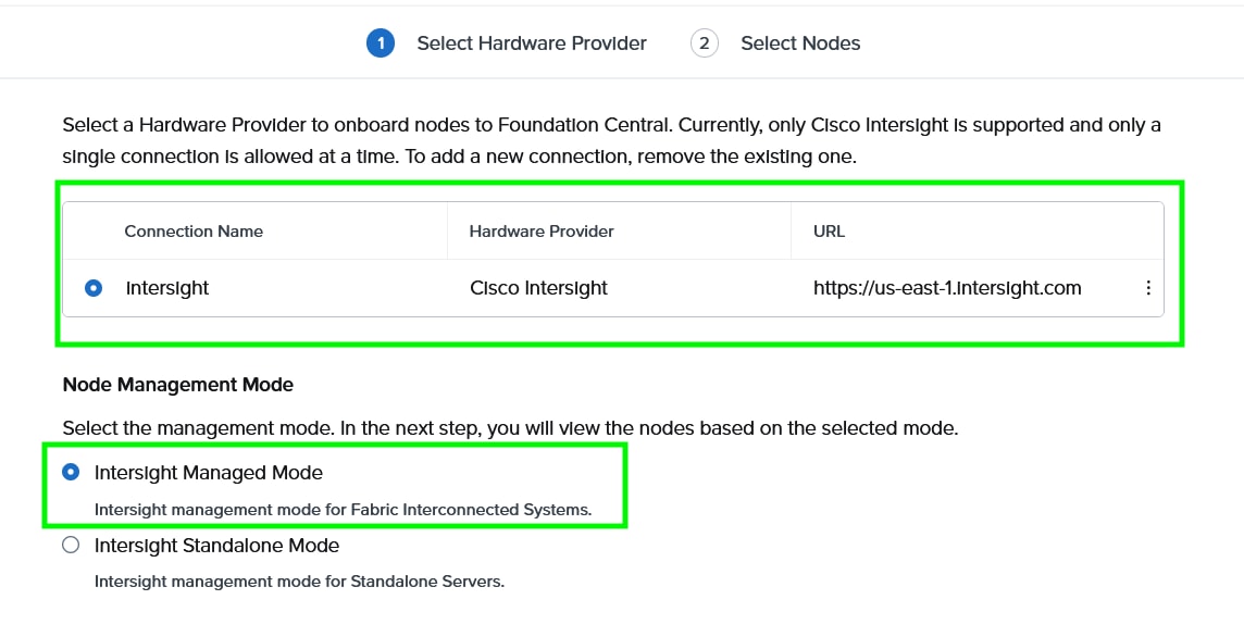
Step 3. Go to the Foundation Central Settings and Connect Hardware Provider. This procedure allows the connection of Foundation Central to Cisco Intersight through the Cisco Intersight API key created in the Intersight configuration. This allows Foundation Central to discover nodes claimed on Cisco Intersight.
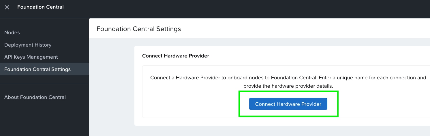
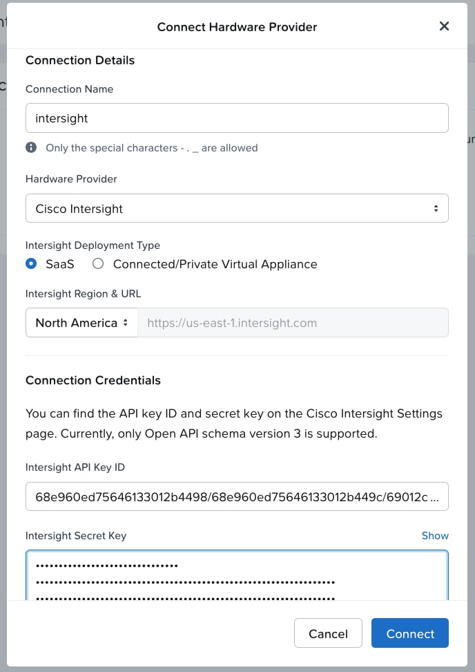
Step 4. Enter the Connection Name, Intersight Deployment Type, Intersight API Key ID, Intersight Secret Key and then click on Connect. Intersight URL is automatically displayed as per the region configured in Foundation Central.
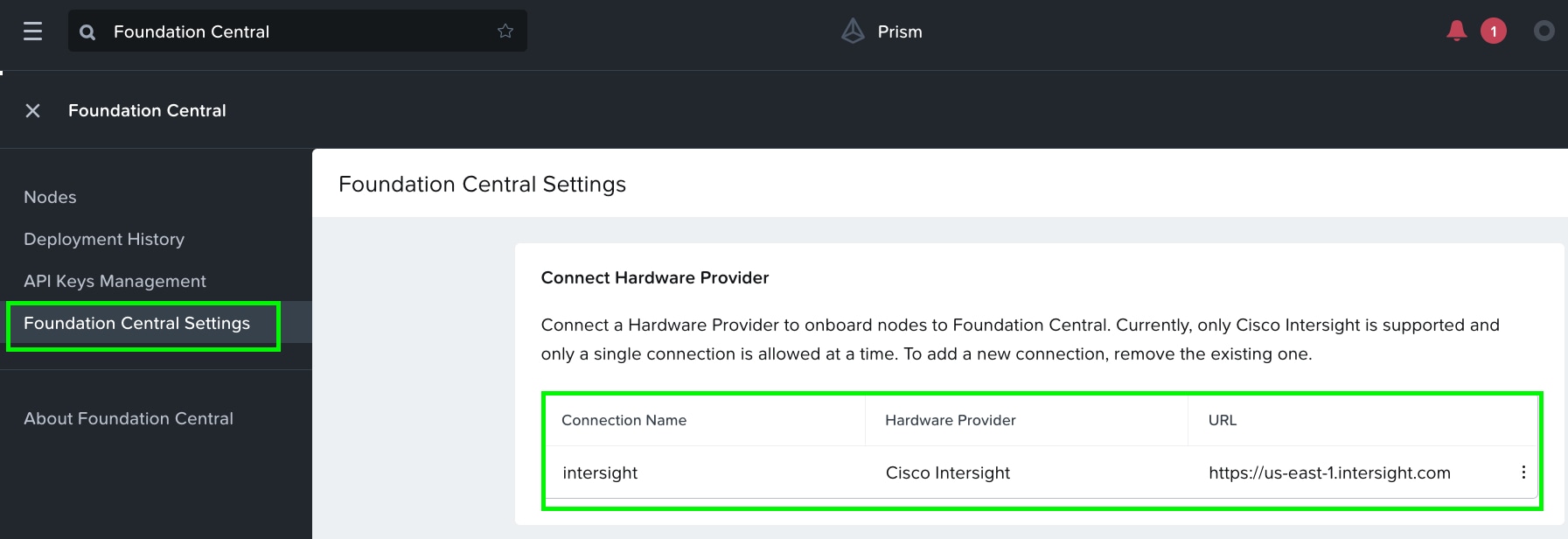
When the authentication to Intersight succeeds, the connection displays under FC settings.
This section provides the procedures to onboard the nodes on Foundation Central and thereafter create the cluster for Cisco UCS X-Series nodes managed in Intersight Managed Mode (IMM).
Procedure 1. Onboard nodes on Foundation Central
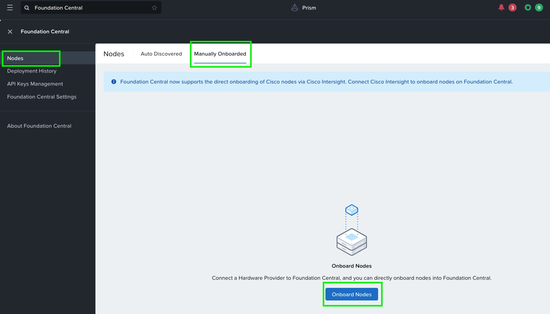
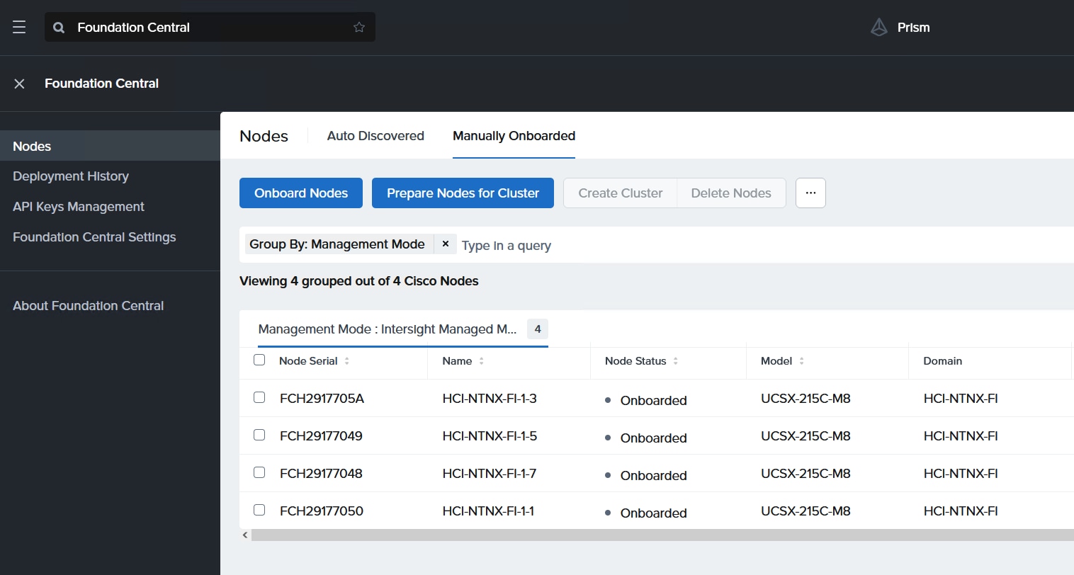
Step 1. Go to Foundation Central, select the Nodes tab and select the Manually Onboarded tab.
Step 2. Click Onboard Nodes.
Step 3. The screen displays the connection details configured for Cisco Intersight. Click Next.
Step 4. Foundation Central connects to Cisco Intersight and displays all the unconfigured nodes existing in Intersight. Select the nodes provisioned for Nutanix and click Onboard.
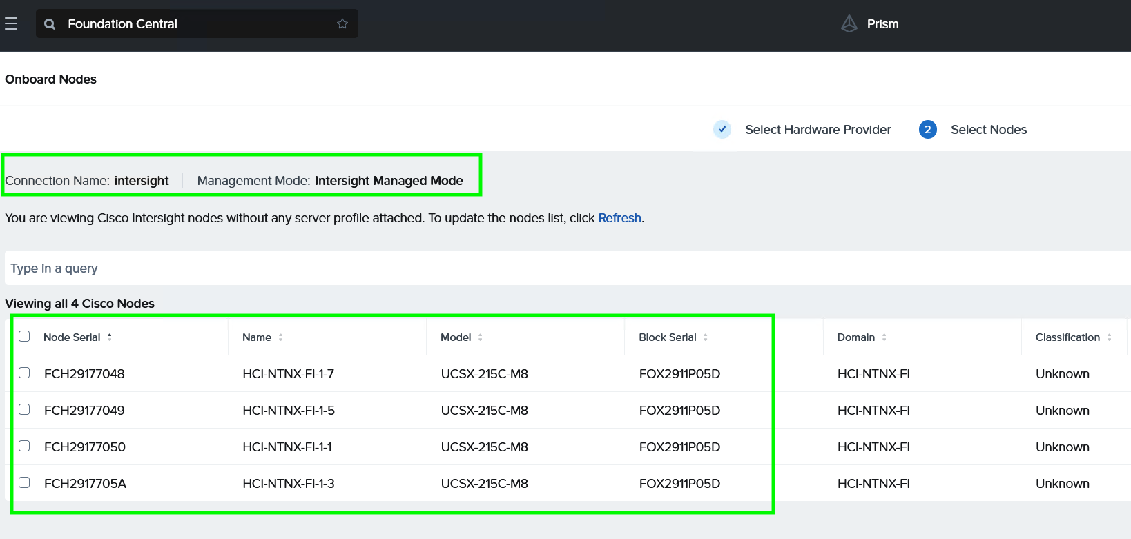
Three Nutanix nodes are onboarded on Foundation Central as shown below:
Procedure 2. Setup Nutanix Cluster
Step 1. Go to Foundation Central, then select the Nodes tab and select the Manually Onboarded tab.
Step 2. Select Onboard Nodes. The Cisco UCS X-Series nodes onboarded for Nutanix Cluster creation display.
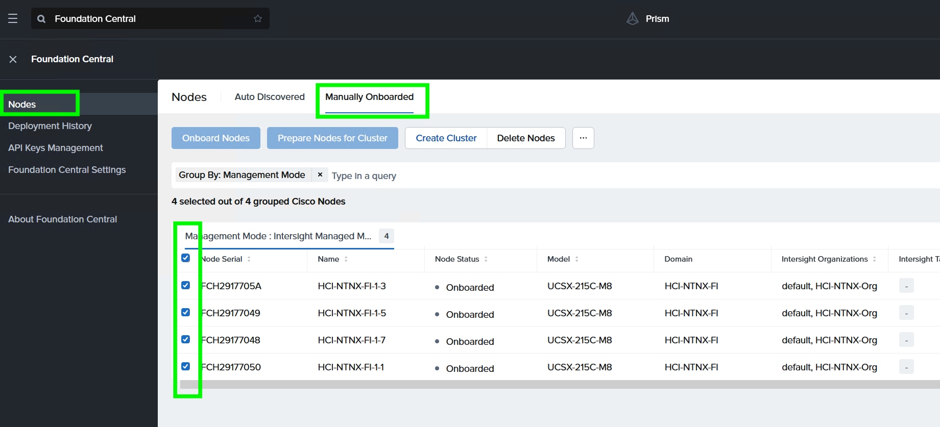
Step 3. Click Create Cluster under the Actions tab.
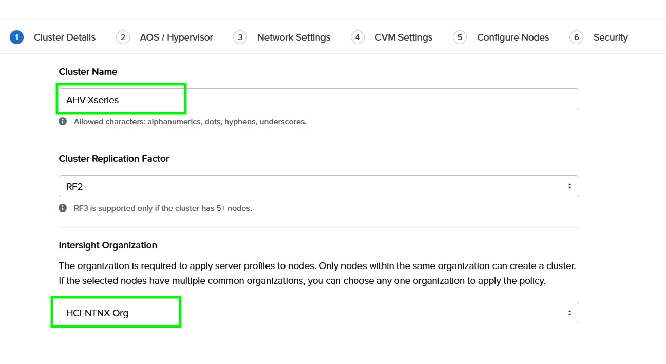
Step 4. Enter a cluster name, since there are four nodes, the replication factor (RF) of cluster would be RF2, select the Intersight organization in which the servers had been claimed. Click Next.
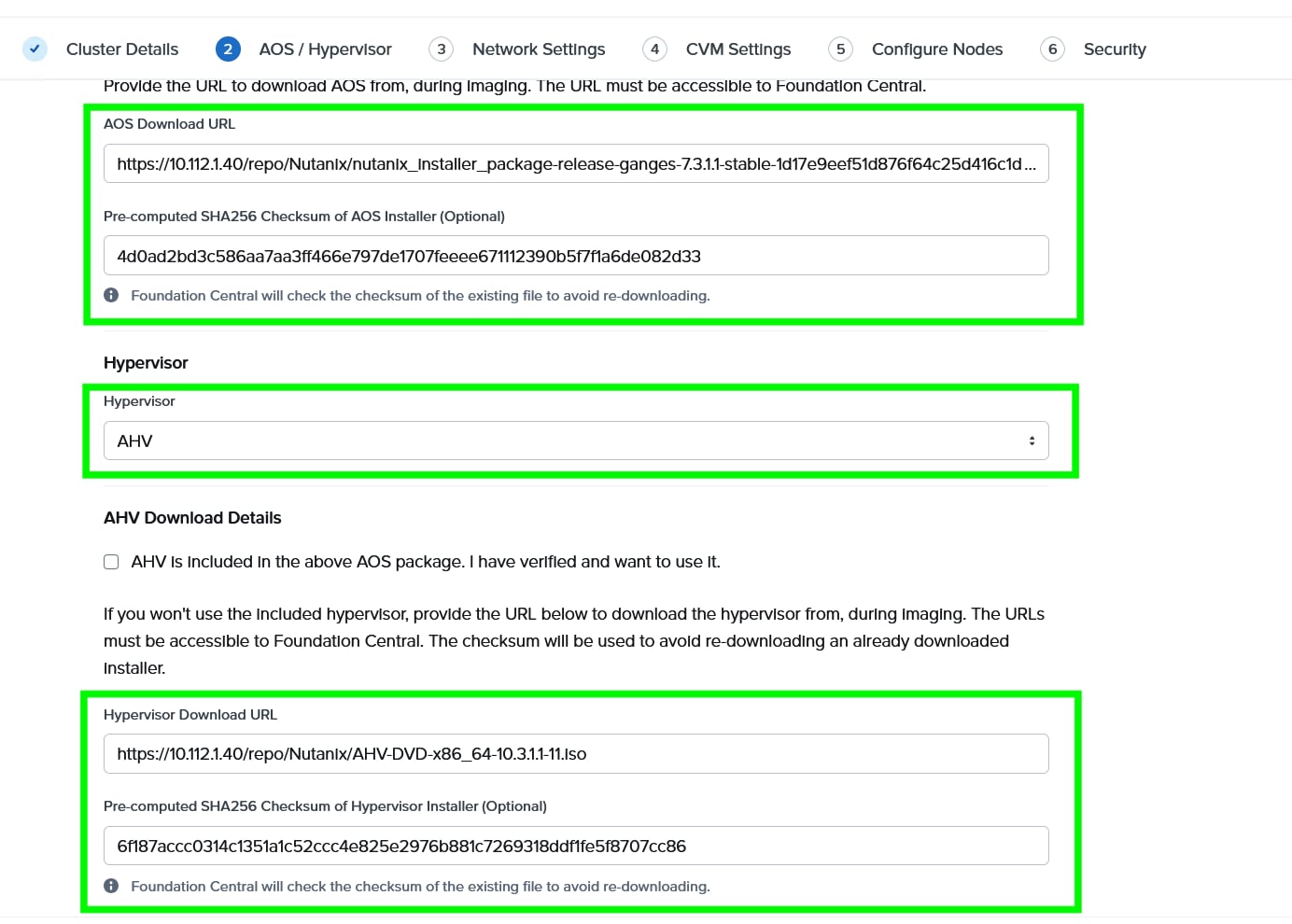
Step 5. Choose I want to image all nodes with AOS and hypervisor Installers. Enter the AOS download URL. You are required to host the Nutanix AOS on a http/https web server. The web server should be reachable from Cisco IMC network. The AOS Download URL and AOS Metadata file URL must be provided, then select AHV as the hypervisor.
Step 6. Provide the Download URL for the AHV installation ISO. You must also provide the SHA256 checksum for the hypervisor installation file being used.
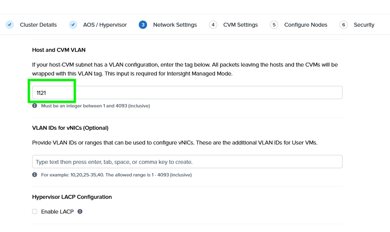
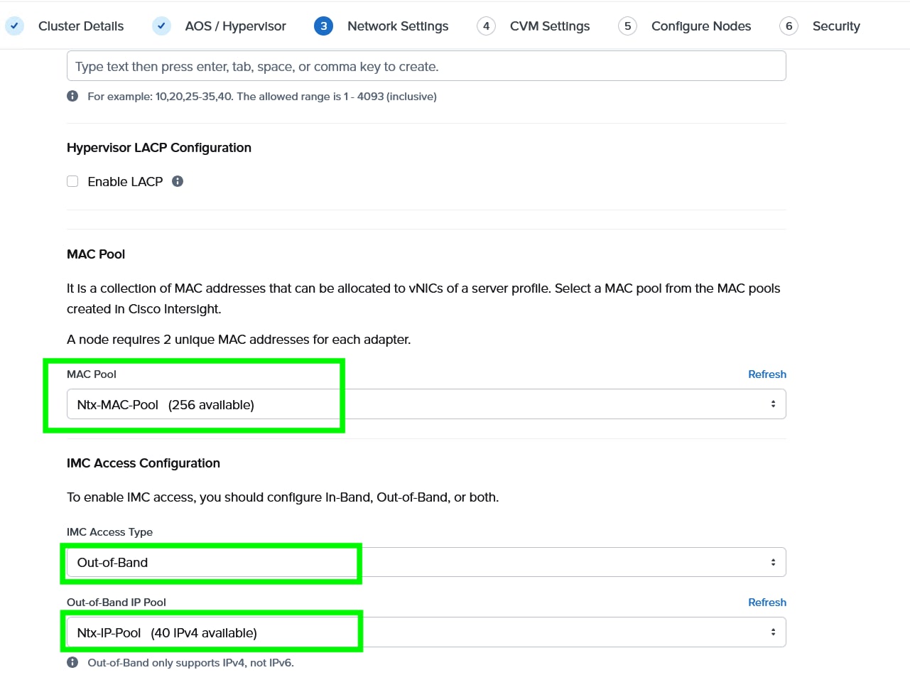
Step 7. Enter the Host and CVM VLAN, then select MAC Pool and IMC Access Configuration previously configured.
Note: You have a choice to enable LACP with AHV. Default mode is active-backup. For more details, go to: https://portal.nutanix.com/page/documents/solutions/details?targetId=BP-2071-AHV-Networking:bp-ahv-networking-best-practices.html. Enable LACP after cluster configuration and is supported only during re-imaging of nodes.
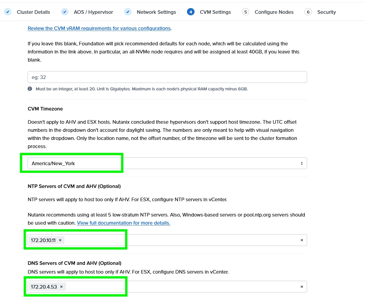
Step 8. Enter the Timezone, DNS and NTP server configuration.
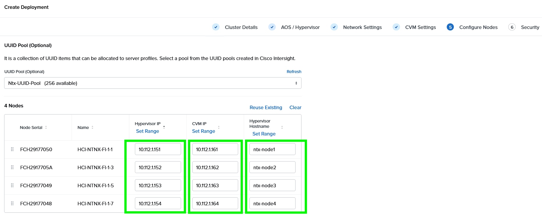
Step 9. Enter the Hypervisor IP, CVM IP, and hostnames for all the nodes configured for cluster and click Next.
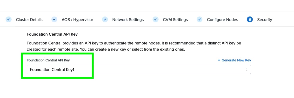
Step 10. Select the Foundation Central API key as created under FC configuration. Click Submit.
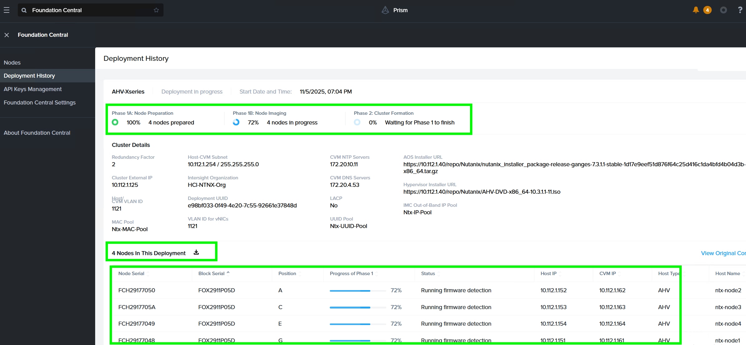
Step 11. Monitor the cluster creation process.
Step 12. When the cluster is created successfully, go to the cluster VIP, and complete the post cluster creation task such as configuration of Storage containers, High availability reservation, iSCSI Data IP configuration, VM network configuration, and address any warnings displayed during NCC checks.
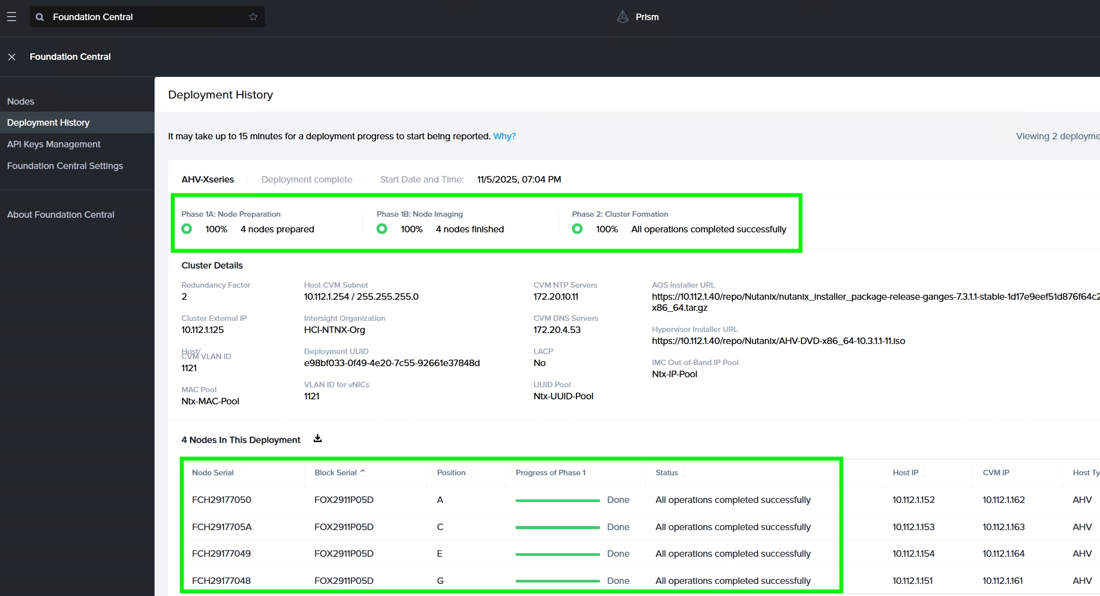
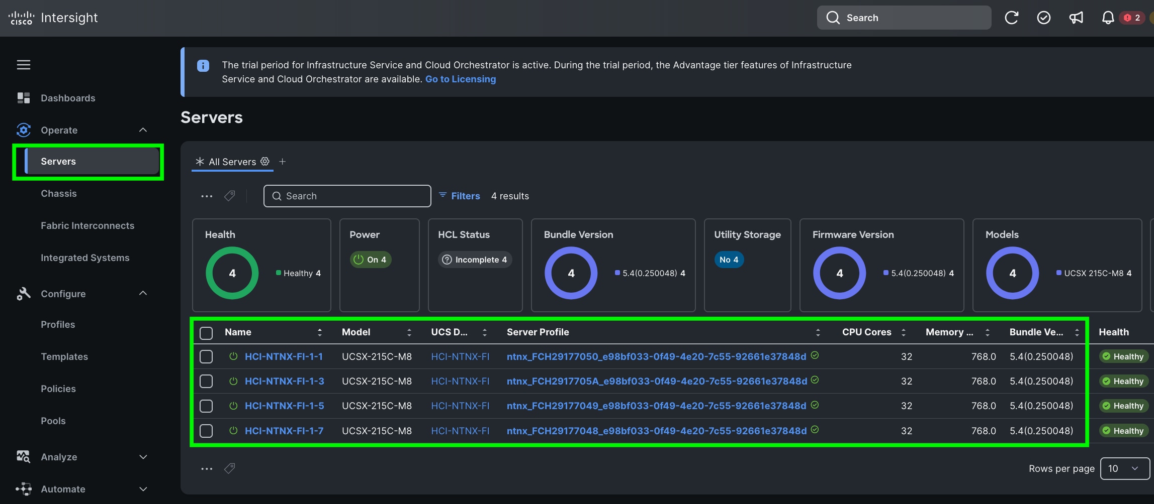
Step 13. Go to Cisco Intersight to view the Server Profile created as part of Day 0 deployment.
This procedure describes the recommended post cluster creation steps.
Procedure 1. Post Cluster Creation task
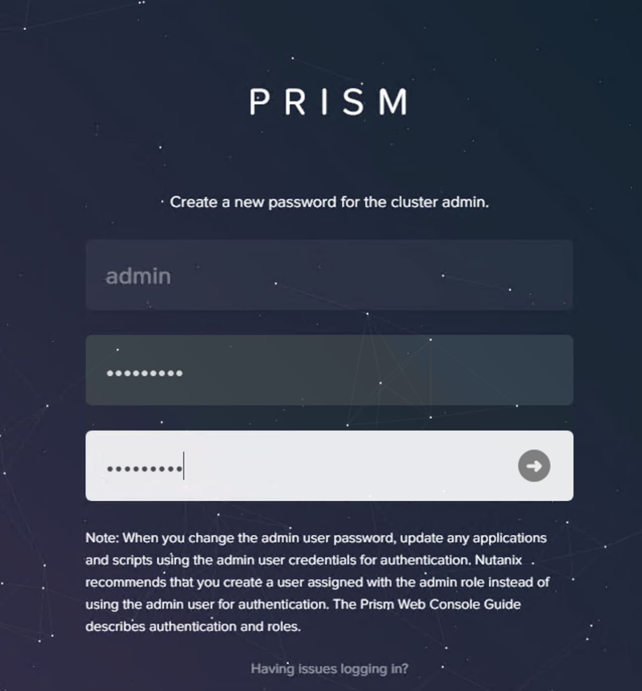
Step 1. Access Prism Element (the built-in version of Prism) at the cluster IP address or an individual controller VM IP address, using HTTPS at port 9440.
Step 2. Default username: admin and password (case sensitive): Nutanix/4u
Note: Password must be changed on first login.
Step 3. Accept EULA and Enable Pulse.
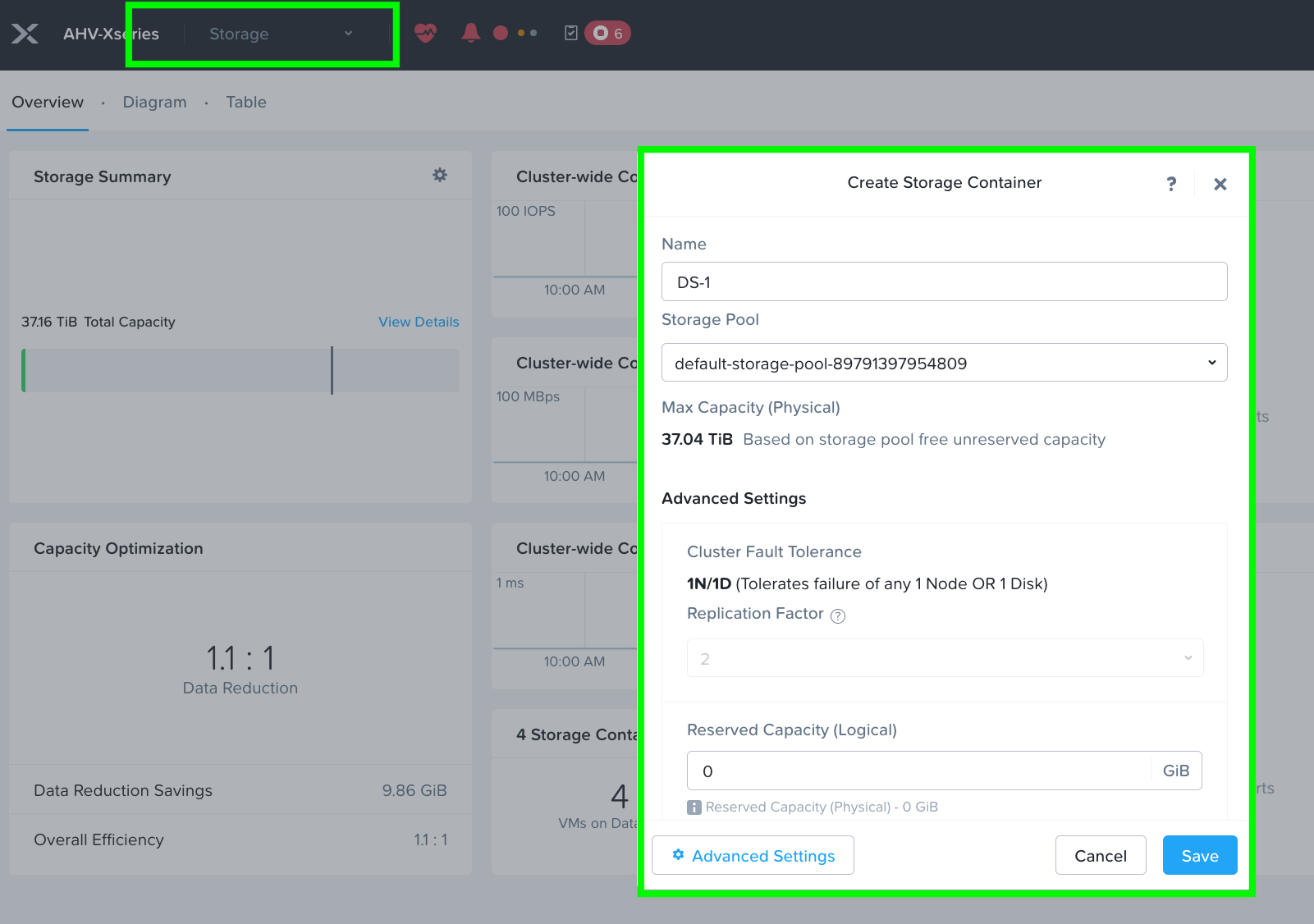
Step 4. Go to the Storage tab and create the storage container. Click Save.
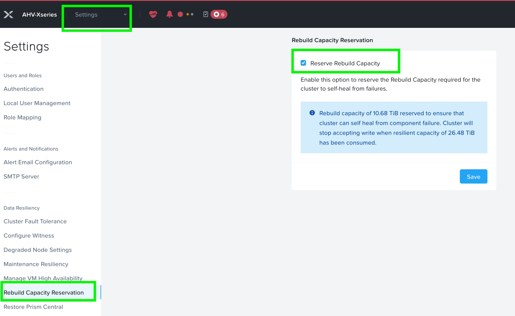
Step 5. Enable Rebuild Capacity Reservation for cluster self-healing from failures. Without this setting enabled, cluster will accept incoming writes even if all blocks cannot completely heal during failures. After enabling, cluster will refuse new writes if they cannot be fully protected during failures.
Step 6. Set iSCSI Data Services IP Address. This is an additional clustered IP address for enabling iSCSI Data Services, which is required to install Prism Central.
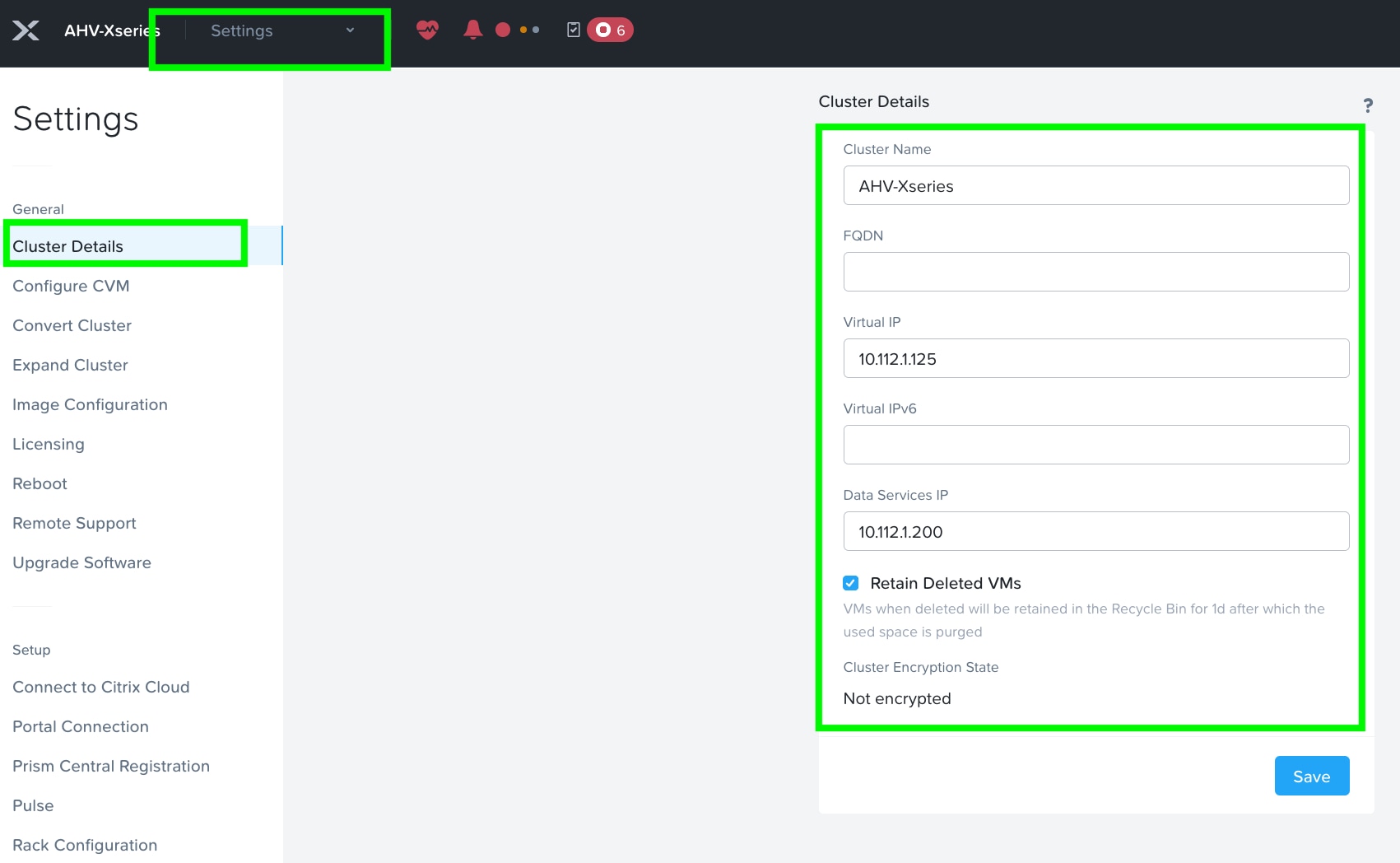
Step 7. Go to Cluster details and enter iSCSI data services IP and enable Retain Deleted VMs for 1 day. Click Save.
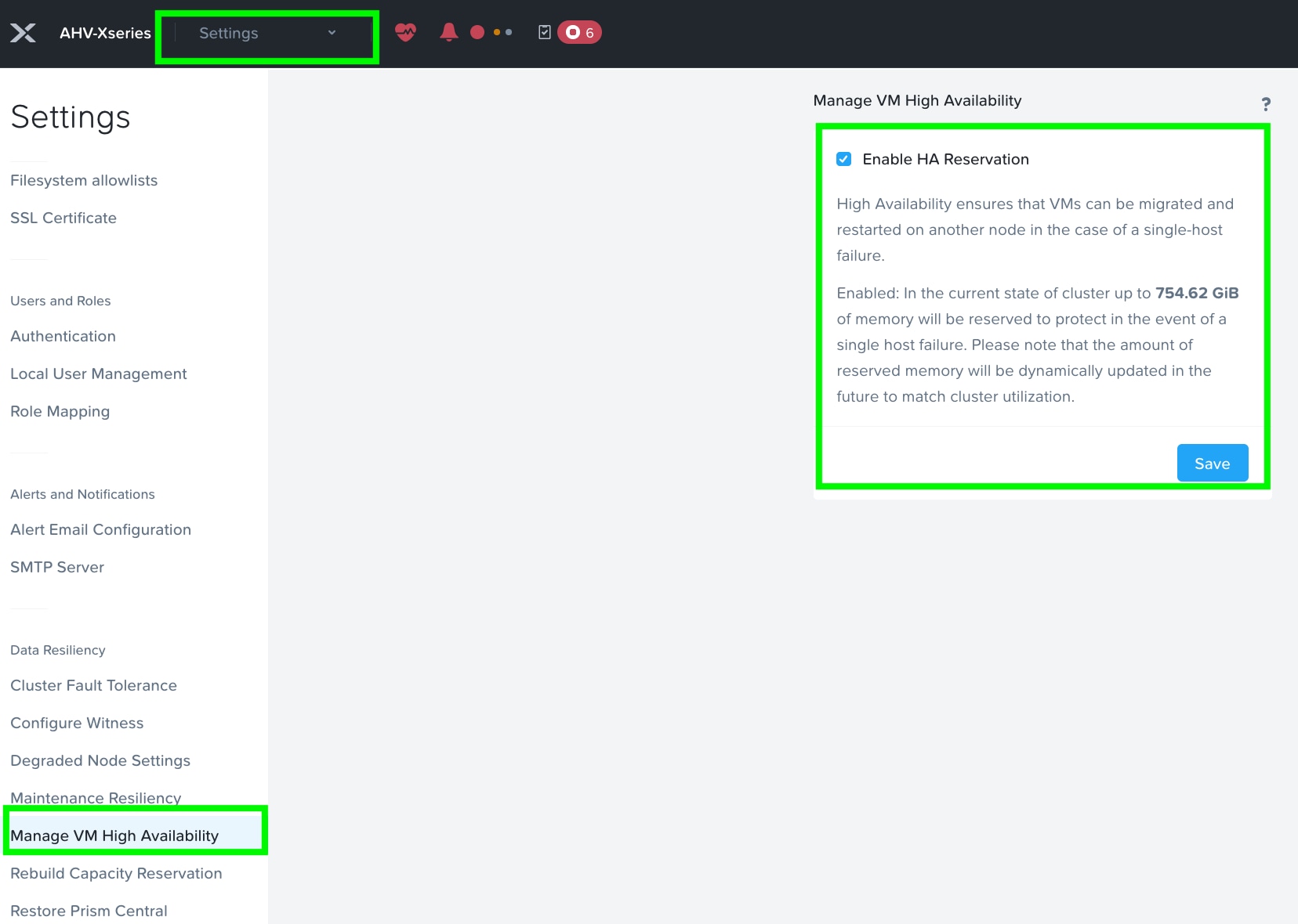
Step 8. Enable VM High Availability Reservation. Go to Settings > Manage VM High Availability and select Enable HA Reservation. Click Save.
Step 9. Create VM Subnet(s). Go to the VM tab and then click on Network Config to create VM network subnet.
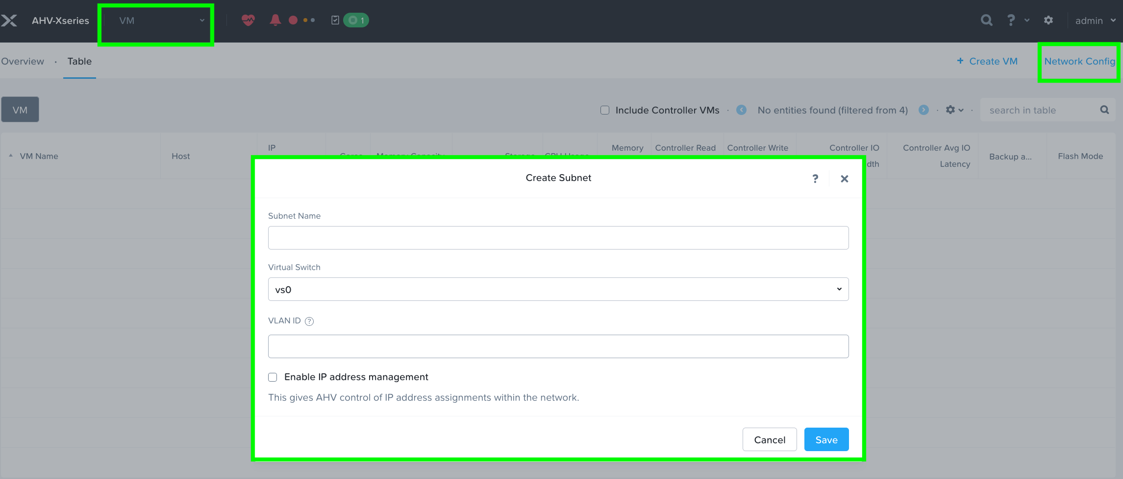
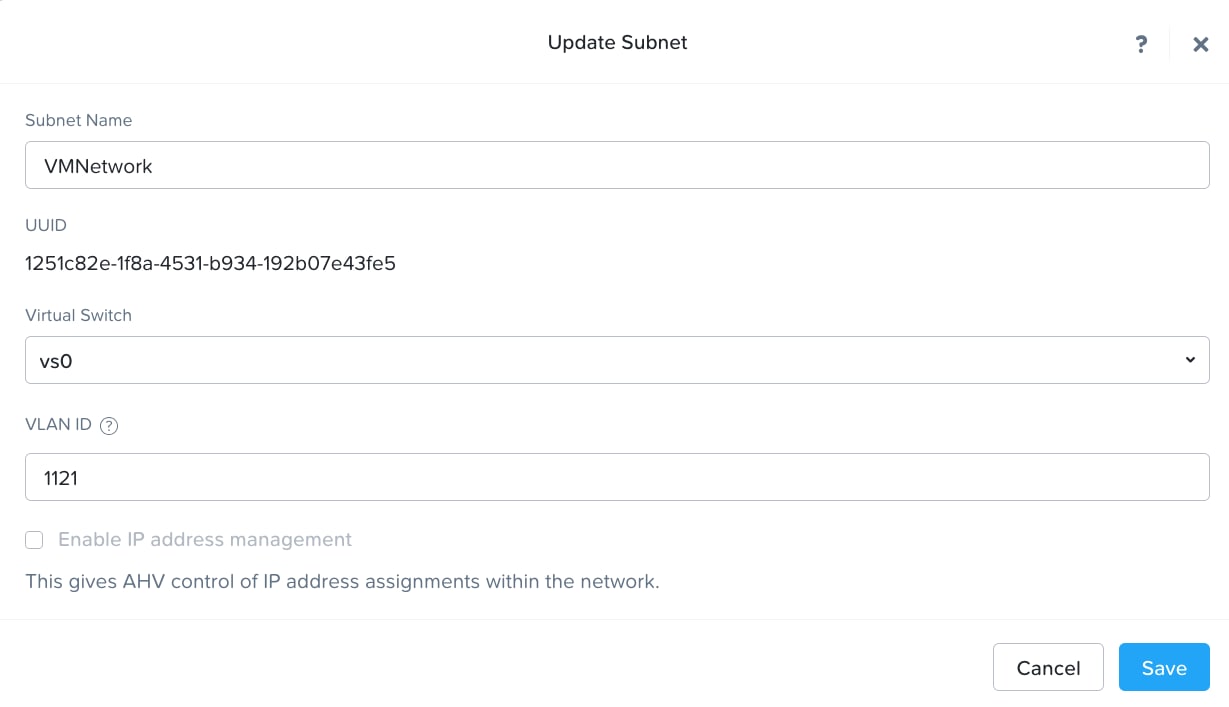
Step 10. Provide the name of Subnet and select Virtual Switch and enter VLAN ID according to your environment.
Note: Do not modify the default virtual switch bond type to Active-Active.
Step 11. Run a NCC check and address warnings such as changing AHV and CVM default passwords. Three accounts on AHV must have their passwords reset: root, admin and nutanix.
Note: The NCC health checks default_password_check, pc_default_password_check and file_server_default_password_check verify if there are any CVMs (Controller VMs), hosts, IPMIs, Prism Central (PC) instances, or File Server VMs with the default credentials. For more information, go to https://portal.nutanix.com/page/documents/kbs/details?targetId=kA00e000000LKXcCAO
About the author
Hardikkumar Vyas, Technical Marketing Engineer, Cisco Systems, Inc.
Hardikkumar Vyas is a member of Cisco Systems’ Cloud and Compute Engineering Group, where he focuses on converged and hyperconverged infrastructure solutions. He holds a master’s degree in electrical engineering and has more than 14 years of experience working with enterprise applications such as Oracle RAC Databases, Splunk, and Nutanix. Hardikkumar has contributed to the design, configuration, implementation, optimization, and validation of infrastructure and best practices for data center applications, with a focus on private and hybrid cloud solutions in Cisco’s data center environment.
Acknowledgements
For their support and contribution to the design, validation, and creation of this Cisco Validated Design, the author would like to thank:
· Tushar Patel, Distinguished Technical Marketing Engineer, Cisco Systems, Inc.
· Brian Everitt, Technical Marketing Engineering Leader, Cisco Systems, Inc.
· Anil Dhiman, Technical Marketing Engineering Leader, Cisco Systems, Inc.
· Hardik Patel, Technical Marketing Engineering Leader, Cisco Systems, Inc.
· John George, Technical Marketing Engineering Leader, Cisco Systems, Inc
Appendix
This appendix contains the following:
· Appendix A – Bill of Materials
· Appendix B – References used in this guide
Appendix A – Bill of Materials
Table 2 provides an example of the Bill of Materials used for one (3) node cluster deployed, used in the testing and reference design described in this document.
| Line Number |
Part Number |
Description |
Quantity |
| 1.0 |
UCSX-M8-MLB |
UCSX M8 Modular Server and Chassis MLB |
1 |
| 1.1 |
DC-MGT-SAAS |
Cisco Intersight SaaS |
1 |
| 1.1.1 |
DC-MGT-IS-SAAS-AD |
Infrastructure Services SaaS/CVA - Advantage |
4 |
| 1.1.2 |
SVS-DCM-SUPT-BAS |
Cisco Support Standard for DCM |
1 |
| 1.2 |
UCSX-9508-D-U |
UCS 9508 Chassis Configured |
1 |
| 1.2.1 |
UCSX-215C-M8 |
UCS X215c M8 Compute Node 2S w/o CPU, Memory, storage, Mezz |
4 |
| 1.2.2 |
COMPUTE-OTHER |
Compute Other Use Case |
1 |
| 1.2.3 |
UCSX-I9108-100G-D |
UCS 9108-100G IFM for 9508 Chassis |
2 |
| 1.2.4 |
UCSX-C-DEBUGCBL-D |
UCSX Compute Node Debug Cable |
1 |
| 1.2.5 |
UCSX-CHASSIS-SW-D |
Platform SW (Recommended) latest release for X9500 Chassis |
1 |
| 1.2.6 |
UCSX-9508-CAK-D |
UCS 9508 Chassis Accessory Kit |
1 |
| 1.2.7 |
UCSX-9508-RBLK-D |
UCS 9508 Chassis Active Cooling Module (FEM slot) |
2 |
| 1.2.8 |
UCSX-9508-ACPEM-D |
UCS 9508 Chassis Rear AC Power Expansion Module |
2 |
| 1.2.9 |
UCSX-9508-KEYAC-D |
UCS 9508 AC PSU Keying Bracket |
1 |
| 1.2.10 |
UCSX-9508-FSBK-D |
UCS 9508 Chassis Front Node Slot Blank |
4 |
| 1.2.11 |
IMM-MANAGED |
Deployment mode for UCS FI connected Servers in IMM mode |
4 |
| 1.2.12 |
UCSX-CPU-A9355 |
AMD 9355 3.55GHz 280W 32C/256MB Cache DDR5 6000MT/s |
4 |
| 1.2.13 |
UCSX-MLV5D200GV2D |
Cisco VIC 15230 2x 100G mLOM X-Series w/Secure Boot |
4 |
| 1.2.14 |
UCSX-M2-480G-D |
480GB M.2 SATA SSD |
8 |
| 1.2.15 |
UCSX-M2-HWRD-FPS |
UCSX Front panel with M.2 RAID controller for SATA drives |
4 |
| 1.2.16 |
UCSX-C-SW-LATEST-D |
Platform SW (Recommended) latest release XSeries ComputeNode |
4 |
| 1.2.17 |
UCSX-TPM2-002D-D |
TPM 2.0 FIPS 140-2 MSW2022 compliant AMD M8 servers |
4 |
| 1.2.18 |
UCS-DDR5-BLK |
UCS DDR5 DIMM Blanks |
48 |
| 1.2.19 |
UCSX-M8A-HS-F |
Front Heatsink for AMD X series servers |
4 |
| 1.2.20 |
UCSX-X10C-PT4F-D |
UCS X10c Compute Pass Through Controller (Front) |
4 |
| 1.2.21 |
UCSX-MRX64G2RE5 |
64GB DDR5-6400 RDIMM 2Rx4 (16Gb) |
48 |
| 1.2.22 |
UCSX-NVMEG4M1920D |
1.9TB 2.5in U.3 15mm P7450 Hg Perf Med End NVMe |
24 |
| 1.2.23 |
UCSX-PSU-2800AC-D |
UCS 9508 Chassis 2800V AC Dual Voltage PSU Titanium |
6 |
| 1.2.24 |
CAB-AC-C6K-TWLK |
Power Cord, 250Vac 16A, twist lock NEMA L6-20 plug, US |
6 |
| 1.3 |
UCSX-FI-6536-D-U |
Fabric Interconnect 6536 for IMM |
1 |
| 1.3.0.1 |
CON-L1NCO-UCSX00F6 |
CX LEVEL 1 8X7XNCDOS Fabric Interconnect 6536 for IMM |
1 |
| 1.3.1 |
N10-MGT018-D |
UCS Manager v4.2 and Intersight Managed Mode v4.2 |
1 |
| 1.3.2 |
UCS-FI-6500-SW |
Perpetual SW License for the 6500 series Fabric Interconnect |
1 |
| 1.3.3 |
UCS-PSU-6536-AC-D |
UCS 6536 Power Supply/AC 1100W PSU - Port Side Exhaust |
2 |
| 1.3.4 |
CAB-9K12A-NA |
Power Cord, 125VAC 13A NEMA 5-15 Plug, North America |
2 |
| 1.3.5 |
QSFP-100G-CU3M |
100GBASE-CR4 Passive Copper Cable, 3m |
16 |
| 1.3.6 |
UCS-ACC-6536-D |
UCS 6536 Chassis Accessory Kit |
1 |
| 1.3.7 |
UCS-FAN-6536-D |
UCS 6536 Fan Module |
6 |
Appendix B – References use in this guide
Cisco Compute Hyperconverged X-Series with Nutanix: https://www.cisco.com/c/en/us/products/hyperconverged-infrastructure/compute-hyperconverged/index.html
Cisco Compute Hyperconverged with Nutanix IMM Field Guide: https://community.cisco.com/t5/unified-computing-system-knowledge-base/cisco-compute-hyperconverged-with-nutanix-imm-field-guide/ta-p/5219852
Cisco Compute Hyperconverged X-Series M8 with Nutanix (CCHC + N) Ordering Guide: https://www.cisco.com/c/en/us/td/docs/HCI-Series/HCI-ordering-guide/hcix_m8_ordering-guide-nutanix-compute.html
Cisco Compute Hyperconverged with Nutanix HCIXNX215c M8 All-NVMe Compute Node: https://www.cisco.com/c/dam/en/us/products/collateral/hyperconverged-infrastructure/compute-hyperconverged-hcixnx215c-m8-specsheet.pdf
Cisco Intersight Saas Help Center: https://intersight.com/help/saas and https://www.cisco.com/c/en/us/products/servers-unified-computing/intersight/index.html
Nutanix reference documentation: https://portal.nutanix.com/
AHV Networking Best Practices: https://portal.nutanix.com/page/documents/solutions/details?targetId=BP-2071-AHV-Networking:bp-ahv-networking-best-practices.html
Cisco Compute Hyperconverged with Nutanix in Intersight Standalone Mode: https://www.cisco.com/c/en/us/td/docs/unified_computing/ucs/UCS_CVDs/CCHC_Nutanix_ISM.html
Nutanix Compatibility and Interoperability Matrix: https://portal.nutanix.com/page/compatibility-interoperability-matrix?selectedHardwareVendors=Cisco&selectedHardwares=HCIXNX215C-M8SN&selectedProcessor=Turin&selectedHypervisorTypes=AHV
Nutanix Downloads: https://portal.nutanix.com/page/downloads/list
For comments and suggestions about this guide and related guides, join the discussion on Cisco Community here: https://cs.co/en-cvds.
ALL DESIGNS, SPECIFICATIONS, STATEMENTS, INFORMATION, AND RECOMMENDATIONS (COLLECTIVELY, "DESIGNS") IN THIS MANUAL ARE PRESENTED "AS IS," WITH ALL FAULTS. CISCO AND ITS SUPPLIERS DISCLAIM ALL WAR-RANTIES, INCLUDING, WITHOUT LIMITATION, THE WARRANTY OF MERCHANTABILITY, FITNESS FOR A PARTICULAR PURPOSE AND NONINFRINGEMENT OR ARISING FROM A COURSE OF DEALING, USAGE, OR TRADE PRACTICE. IN NO EVENT SHALL CISCO OR ITS SUPPLIERS BE LIABLE FOR ANY INDIRECT, SPECIAL, CONSEQUENTIAL, OR INCIDENTAL DAMAGES, INCLUDING, WITHOUT LIMITATION, LOST PROFITS OR LOSS OR DAMAGE TO DATA ARISING OUT OF THE USE OR INABILITY TO USE THE DESIGNS, EVEN IF CISCO OR ITS SUPPLIERS HAVE BEEN ADVISED OF THE POSSIBILITY OF SUCH DAMAGES.
THE DESIGNS ARE SUBJECT TO CHANGE WITHOUT NOTICE. USERS ARE SOLELY RESPONSIBLE FOR THEIR APPLICA-TION OF THE DESIGNS. THE DESIGNS DO NOT CONSTITUTE THE TECHNICAL OR OTHER PROFESSIONAL ADVICE OF CISCO, ITS SUPPLIERS OR PARTNERS. USERS SHOULD CONSULT THEIR OWN TECHNICAL ADVISORS BEFORE IMPLE-MENTING THE DESIGNS. RESULTS MAY VARY DEPENDING ON FACTORS NOT TESTED BY CISCO.
CCDE, CCENT, Cisco Eos, Cisco Lumin, Cisco Nexus, Cisco StadiumVision, Cisco TelePresence, Cisco WebEx, the Cisco logo, DCE, and Welcome to the Human Network are trademarks; Changing the Way We Work, Live, Play, and Learn and Cisco Store are service marks; and Access Registrar, Aironet, AsyncOS, Bringing the Meeting To You, Catalyst, CCDA, CCDP, CCIE, CCIP, CCNA, CCNP, CCSP, CCVP, Cisco, the Cisco Certified Internetwork Expert logo, Cisco IOS, Cisco Press, Cisco Systems, Cisco Systems Capital, the Cisco Systems logo, Cisco Unified Computing System (Cisco UCS), Cisco UCS B-Series Blade Servers, Cisco UCS C-Series Rack Servers, Cisco UCS S-Series Storage Servers, Cisco UCS X-Series, Cisco UCS Manager, Cisco UCS Management Software, Cisco Unified Fabric, Cisco Application Centric Infrastructure, Cisco Nexus 9000 Series, Cisco Nexus 7000 Series. Cisco Prime Data Center Network Manager, Cisco NX-OS Software, Cisco MDS Series, Cisco Unity, Collaboration Without Limitation, EtherFast, EtherSwitch, Event Center, Fast Step, Follow Me Browsing, FormShare, GigaDrive, HomeLink, Internet Quotient, IOS, iPhone, iQuick Study, LightStream, Linksys, MediaTone, MeetingPlace, MeetingPlace Chime Sound, MGX, Networkers, Networking Academy, Network Registrar, PCNow, PIX, PowerPanels, ProConnect, ScriptShare, SenderBase, SMARTnet, Spectrum Expert, StackWise, The Fastest Way to Increase Your Internet Quotient, TransPath, WebEx, and the WebEx logo are registered trade-marks of Cisco Systems, Inc. and/or its affiliates in the United States and certain other countries. (LDW_P1)
All other trademarks mentioned in this document or website are the property of their respective owners. The use of the word partner does not imply a partnership relationship between Cisco and any other company. (0809R)