Product Overview
This chapter provides a functional overview of the Cisco Redundant Power System 2300 and covers these topics:
Product Description
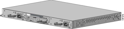
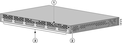
The Cisco RPS 2300 (PWR-RPS2300), also known as the RPS 2300, is a redundant power system that provides seamless failover for internal power supply failures for up to six network devices. It automatically senses if an internal power supply of a connected device fails and immediately supplies power to the failed device. The device then has continuous uptime with no need to reboot. The RPS 2300 is shown in Figure 1-1.
The RPS 2300 has two field-replacable-unit (FRU) power supply modules that are inserted into the slots on the RPS 2300 front panel. Depending on the connected switch power requirements, you can use up to two 750-W or two 1150-W power supply modules. The number of switches that the RPS 2300 can back up depends on the number and capacity of the power supply modules in the RPS 2300. Table 1-3 shows the supported power supply configurations.
The six DC ports on the RPS 2300 provide the power and serial management bus (SMB) communication signals to the Catalyst 3750-E and 3560-E switches. The RPS 2300 communicates with each switch through the SMB embedded in the 22-pin RPS cable. This allows all connected 3750-E and 3560-E switches to simultaneously communicate with the RPS 2300.
When connected to the Catalyst 3750-E and 3560-E switches, you can configure these RPS 2300 features through the switch software:
•![]() Enable RPS active or standby mode for each connected device
Enable RPS active or standby mode for each connected device
•![]() Configure the switch priority for RPS support
Configure the switch priority for RPS support
•![]() List the connected switches and their power-supply module size
List the connected switches and their power-supply module size
•![]() Report when a switch is powered by the RPS
Report when a switch is powered by the RPS
•![]() Report the RPS power-supply module status
Report the RPS power-supply module status
•![]() Read and monitor backup, failure, and exception history
Read and monitor backup, failure, and exception history
The RPS 2300 supports the Catalyst 3750-E and 3560-E switches and other Cisco devices. For a complete list of supported products, see the online Redundant Power System 2300 Compatibility Matrix posted with the RPS 2300.
Figure 1-1 Cisco RPS 2300
Features
The RPS 2300 has these features:
•![]() Seamless failover if a switch power supply fails.
Seamless failover if a switch power supply fails.
•![]() Automatic backoff for Catalyst 3750-E and 3560-E switches.
Automatic backoff for Catalyst 3750-E and 3560-E switches.
When the internal power supply of the connected switch resumes operation, the switch sends a back-off command to the RPS 2300, which seamlessly backs off.
•![]() Six output channels to support multiple devices.
Six output channels to support multiple devices.
•![]() Back up power for 24-port and 48-port Power over Ethernet (PoE) switches, providing 15.4-W power on all ports when using the appropriate power supply modules.
Back up power for 24-port and 48-port Power over Ethernet (PoE) switches, providing 15.4-W power on all ports when using the appropriate power supply modules.
•![]() Two 750-W or 1150-W power supply modules
Two 750-W or 1150-W power supply modules
•![]() Front-panel LEDs for DC output power, fans, and temperature status
Front-panel LEDs for DC output power, fans, and temperature status
•![]() Manageability through the Catalyst 3750-E and 3560-E switch software
Manageability through the Catalyst 3750-E and 3560-E switch software
•![]() High-availability for switches and routers that use IP telephony
High-availability for switches and routers that use IP telephony
•![]() Configuration settings to manage the DC-output power priority for the six output channels to enhance availability for switches and routers carrying mission-critical data.
Configuration settings to manage the DC-output power priority for the six output channels to enhance availability for switches and routers carrying mission-critical data.
You can configure and clear the port priority through the Catalyst 3750-E and 3560-E switch software and clear the port priority from the RPS 2300 front panel.
•![]() Small form-factor suitability for rack-mounting to provide maximum wiring-closet port density
Small form-factor suitability for rack-mounting to provide maximum wiring-closet port density
•![]() Two RPS cables:
Two RPS cables:
–![]() 22-pin-to-22-pin cable for Catalyst 3750-E and 3560-E switches (CAB-RPS-2300-E=)
22-pin-to-22-pin cable for Catalyst 3750-E and 3560-E switches (CAB-RPS-2300-E=)
–![]() 22-pin-to-14-pin cable for other supported Cisco devices (CAB-RPS-2300=)
22-pin-to-14-pin cable for other supported Cisco devices (CAB-RPS-2300=)
•![]() Compatibility with Catalyst 2950, 2960, 3550, 3560, 3750, 3750-E and 3560-E switches, the Catalyst Express 500 switch (select Power over Ethernet models only), and Cisco 2811, 2821, 2851, and 3825 Integrated Service Routers.
Compatibility with Catalyst 2950, 2960, 3550, 3560, 3750, 3750-E and 3560-E switches, the Catalyst Express 500 switch (select Power over Ethernet models only), and Cisco 2811, 2821, 2851, and 3825 Integrated Service Routers.
Supported Devices
The RPS 2300 supports specific Cisco products. For a complete list, see the Cisco RPS 2300 Switch Compatibility Matrix on Cisco.com.
Deployment Strategies
You can use the RPS 2300 in various network deployment scenarios.
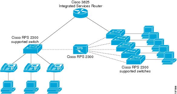
One application might be in a voice and data network in which the switches are connected to Cisco IP phones and PCs. Figure 1-2 shows the RPS 2300 connected to multiple switches in a converged voice and data network. Connecting it to the switches prevents voice network failures that are caused by switch failures and ensures seamless voice and data network operation.
Figure 1-2 The RPS 2300 in a Voice and Data Network
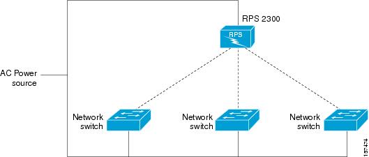
Another application might be that of using traditional 10/100/1000 Ethernet switches that carry mission-critical data. These applications would typically use one RPS 2300 to support one to six switches, as shown in Figure 1-3.
In this configuration, both the RPS 2300 and the switches might not share the same AC power source.
Figure 1-3 RPS 2300 Group of Switches and a Single AC Power Source
If up to two devices have a power-supply or power-related failure, the RPS 2300 immediately supplies power and is no longer available as a backup source for the other devices. The RPS 2300 sends status information to the network management software to alert you that the other devices connected to it are not supported until the failed device or the power supply in the failed device is repaired or replaced.
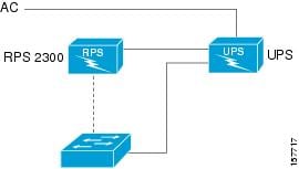
To support mission-critical applications, the RPS 2300 must have enough power to support all connected devices if all of the devices fail. Figure 1-4 shows the RPS 2300 connected to more than one AC source, with the RPS 2300 and the switches using different AC power sources. This deployment provides protection if both a switch power supply and an AC source fail.
Figure 1-4 RPS 2300 One-to-One Redundancy with Multiple AC Power Sources
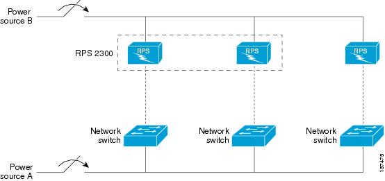
If source A loses power, each switch continues to operate by receiving power from the attached RPS 2300. When the power to source A returns, the RPS 2300 automatically allows the internal power supplies of these switches powered by source A to resume receiving power from their own internal power supplies.
If the RPS 2300 has two power supply modules installed, the RPS 2300 can provide one-to-one support for up to two switches.

Note ![]() An RPS protects network devices against internal power supply failures and AC circuit failures. An uninterruptable power supply (UPS) protects network devices against interruption of utility power. For maximum availability, always use the RPS 2300 with a UPS (Figure 1-5).
An RPS protects network devices against internal power supply failures and AC circuit failures. An uninterruptable power supply (UPS) protects network devices against interruption of utility power. For maximum availability, always use the RPS 2300 with a UPS (Figure 1-5).
Figure 1-5 The RPS 2300 Connected to a UPS
The RPS 2300 provides DC-output port prioritization. This feature can improve the availability of network equipment.
The RPS 2300 provides backup power to a connected device until its power budget is fully allocated. Switches and routers connected to the RPS 2300 are backed up in the order that it detects a power loss. If a device looses power after the RPS 2300 has backed up the maximum number of ports, that device does not receive power from the RPS 2300.
If you consider that a particular device is mission-critical, you can configure the port priority from 1 to 6 by using the switch software. Specifying a value of 1 assigns the port and its connected devices the highest priority, and specifying a value of 6 assigns the port and its connected devices the lowest priority. If multiple switches connected to the RPS 2300 need power, it provides power to the switches with the highest priorities. If the RPS 2300 still has power available, it can then provide power to the switches with lower priorities. For more information about configuring port priorities on the RPS 2300, see the Catalyst 3750-E and Catalyst 3560-E Switch Command Reference.
Front Panel Description
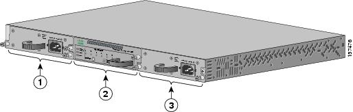
The RPS 2300 front panel has three slots, one for the fan module (which contains the RPS LEDs and the Select/Standby active buttons), and two slots for the power supply modules (Figure 1-6).
Figure 1-6 RPS 2300 Front Panel
|
|
Power supply module |
|
|
Fan module |
|
|
Power supply module |
Fan Module
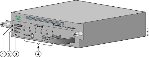
The RPS 2300 fan module includes the system status LEDs, the DC output power LEDs, and the Select and the Standby/Active buttons for the RPS 2300 (see Figure 1-7).
The RPS 2300 supports hot swapping of the fan module. You can remove and replace the module without disconnecting the system power and without interrupting normal system operation. For information about installing and removing the fan module, see "Power Supply and Fan Module Installation" section.
LEDs
The LEDs on the front of the fan module (see Figure 1-7) shows the RPS 2300 status and if it is powering a connected device. The fan module has three bicolor LEDs for system status and six bicolor LEDs for DC port status, as described in Table 1-1 and Table 1-2.
Note ![]() The power supply modules have two LEDs that show the AC power status and the power supply status. For information about these LEDs, see "Power Supply Module LEDs" section.
The power supply modules have two LEDs that show the AC power status and the power supply status. For information about these LEDs, see "Power Supply Module LEDs" section.
Figure 1-7 RPS 2300 LEDs
|
|
STDBY/ACTIVE LED |
|
Fan LED |
|
|
Temperature LED |
|
DC output LEDs |
The six DC output LEDs display the status of the six RPS output connectors that you use to connect the RPS 2300 to the switch. The output LEDs are numbered 1 to 6, which corresponds to the numbers on the DC outputs. Table 1-2 lists the LED colors and their meanings.
Select and Standby/Active Buttons
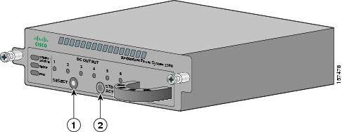
The RPS 2300 has a Select button and a Standby/Active button on the front of the fan module. You can use these buttons to select an RPS port to place the RPS 2300 or an individual port in active or standby mode. Figure 1-8 shows the Select and Standby/Active buttons.
•![]() Use the Select button to select all RPS ports or an individual port.
Use the Select button to select all RPS ports or an individual port.
•![]() Use the Standby/Active button to change the selected port (or all ports) between standbymode (blinking amber) and active mode (solid green). The STDBY/ACTIVE LED displays the port status.
Use the Standby/Active button to change the selected port (or all ports) between standbymode (blinking amber) and active mode (solid green). The STDBY/ACTIVE LED displays the port status.
Note ![]() The RPS 2300 and all DC ports are in active mode when it powers up.
The RPS 2300 and all DC ports are in active mode when it powers up.
To change the RPS 2300 or an individual port to standby or active mode, follow these steps:
Step 1 ![]() Press the Select button. When you press it the first time, all ports are selected, and all six port LEDs blink amber and green.
Press the Select button. When you press it the first time, all ports are selected, and all six port LEDs blink amber and green.
Step 2 ![]() Continue pressing the Select button until the desired port blinks amber and green.
Continue pressing the Select button until the desired port blinks amber and green.
Step 3 ![]() Press the Standby/Active button to place the port in either standby or active mode.
Press the Standby/Active button to place the port in either standby or active mode.
Note ![]() If you press the Standby/Active button on the RPS 2300 before pressing the Select button, the RPS toggles all six ports between active mode and standby mode. If this occurs, press the Select button again to select the desired port.
If you press the Standby/Active button on the RPS 2300 before pressing the Select button, the RPS toggles all six ports between active mode and standby mode. If this occurs, press the Select button again to select the desired port.
Step 4 ![]() Repeat this procedure for all six ports on the RPS 2300.
Repeat this procedure for all six ports on the RPS 2300.
Note ![]() When the RPS 2300 is in standby mode, the RPS LED on the connected device blinks amber; this means that the RPS 2300 is connected but is not functioning. When you press the Standby/Active button, the RPS LED that is on the connected device changes to green to show that the RPS 2300 is operating properly
When the RPS 2300 is in standby mode, the RPS LED on the connected device blinks amber; this means that the RPS 2300 is connected but is not functioning. When you press the Standby/Active button, the RPS LED that is on the connected device changes to green to show that the RPS 2300 is operating properly
You can configure the RPS port priority from 1 to 6 by using the switch software. Specifying a value of 1 assigns the port and its connected devices the highest priority, and specifying a value of 6 assigns the port and its connected devices the lowest priority. If multiple switches connected to the RPS 2300 need power, it provides power to the switches with the highest priorities. If the RPS 2300 still has power available, it can then provide power to the switches with lower priorities. For more information about configuring port priorities on the RPS 2300, see the Catalyst 3750-E and Catalyst 3560-E Switch Command Reference.
To manually reset the ports to the default settings, press both the Select and Standby/Active buttons for 3 seconds, and then release. All system and port LEDs flash green, then amber before the RPS 2300 begins operating with the default port priority settings.
Figure 1-8 Select and Standby/Active Buttons
|
|
Select button |
|
|
Standby/Active button |
Power Supply Modules
The RPS 2300 is powered through the power supply modules. The modules slide into the power supply slots in the front of the RPS 2300 and use their own AC power cord. (See Figure 1-6.) Both modules use a 16-AWG cord and a 15-A, 110-VAC power connector.
The RPS 2300 supports these power supply modules:
•![]() C3K-PWR-1150AC
C3K-PWR-1150AC
•![]() C3K-PWR-750AC
C3K-PWR-750AC
Note ![]() The RPS 2300 does not support the C3K-PWR-265AC and C3K-PWR-265DC power supply modules.
The RPS 2300 does not support the C3K-PWR-265AC and C3K-PWR-265DC power supply modules.
The RPS 2300 can be configured with one or two power supply modules. If you install two power-supply modules they must be the same type. You cannot insert a 750-W and a 1150-W power supply module in the RPS 2300 at the same time.
Note ![]() If you ordered only one power-supply module, a spare power supply insert ships with the RPS 2300. If you ordered two power-supply modules, you can order the power supply insert (BLNK-RPS2300=) as a spare part.
If you ordered only one power-supply module, a spare power supply insert ships with the RPS 2300. If you ordered two power-supply modules, you can order the power supply insert (BLNK-RPS2300=) as a spare part.
If only one power supply module is installed in the RPS 2300, the empty power supply slot in the RPS 2300 front panel must have the spare power supply insert installed. The insert maintains proper airflow through the RPS 2300, and provides proper cooling.

The RPS 2300 can simultaneously back up to two switches. Table 1-3 shows the number of switches that the RPS 2300 can back up and the supported power supply configurations.
|
|
||||
|---|---|---|---|---|
|
|
|
|
|
|
1 Catalyst 3750-E or Catalyst 3560-E switches powered by the 1150-W power supply module |
|
|
|
|
All other supported network devices |
1 |
2 |
1 |
2 |
1 These switches can also be powered by the 750-W power supply module with reduced PoE capacity. |
For information about installing and removing the power-supply modules and for power supply specifications, see Power Supply and Fan Module Installation and "."
Power Supply Module LEDs
The power supply modules have two status LEDs. Table 1-4 lists the LED colors and their meanings.
Rear Panel Description
The RPS 2300 rear panel has six DC output connectors (numbered 1 to 6) that you use to connect to the switch (Figure 1-9). These ports provide the power and communication signals to the Catalyst 3750-E and the 3560-E switches.
Figure 1-9 RPS 2300 Rear Panel
.
|
|
Ground lug |
3 |
DC output connectors |
|
|
Fan exhaust |
The DC output connectors require a cable to connect to the switch. You can use two types of RPS cables. See the "Cabling Options" section and "Connector and Cable Specifications."
RPS Airflow Patterns
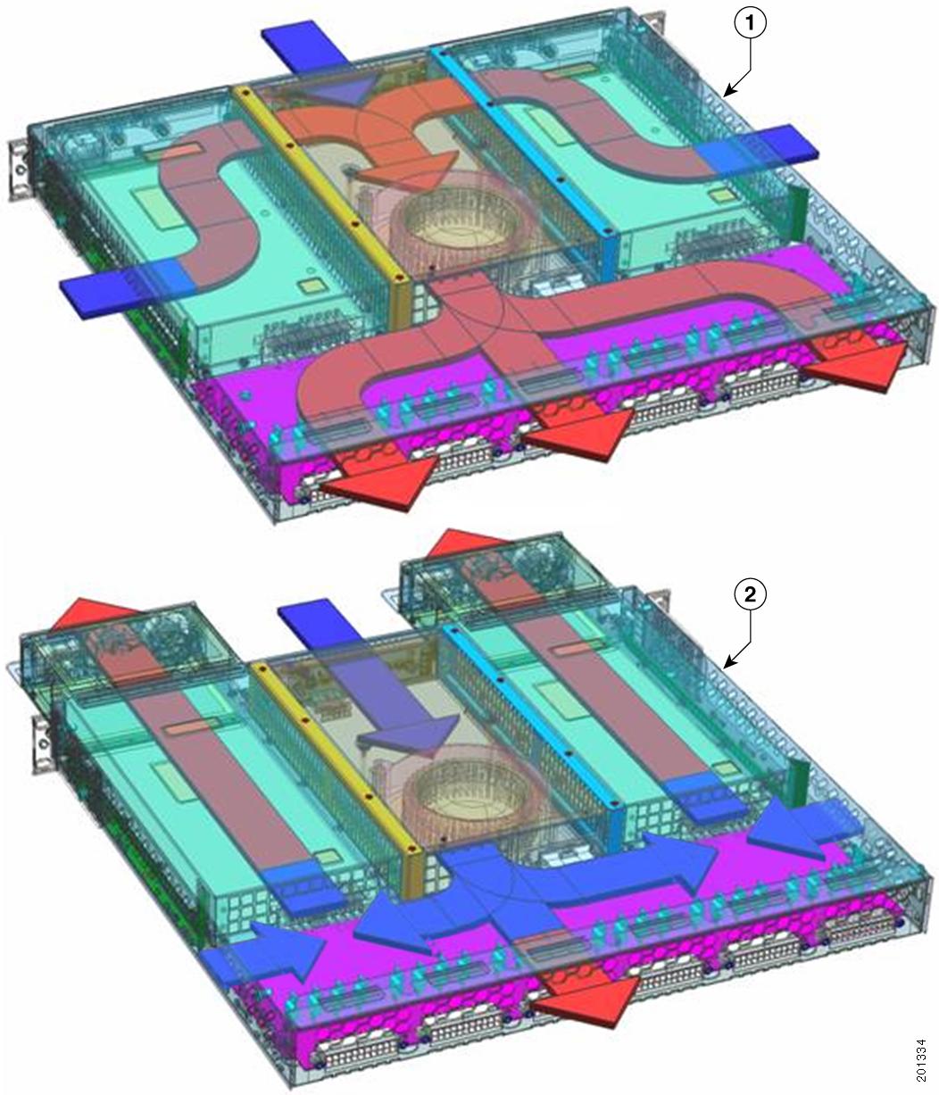
The RPS 2300 air circulation system consists of the fan module and the power supply modules that are installed in the RPS front panel. The airflow patterns vary depending on the RPS power supply configuration.
Figure 1-10 shows the airflow patterns for the RPS. The blue arrow shows cool air flow, and the red arrow shows warm air flow. Table 1-5 describes the RPS airflow patterns and the power supply configurations.
Figure 1-10 RPS 2300 Airflow Patterns
|
|
Airflow pattern with two 750-W power supplies |
|
|
Airflow pattern with two 1150-W power supplies |
Management Options
If a Catalyst 3750-E or 3560-E switch is attached to the RPS 2300, you can configure and manage the RPS 2300 through the switch software.
This section provides information about configuring and managing the
RPS 2300:
•![]() Cisco IOS CLI
Cisco IOS CLI
The switch CLI is based on Cisco IOS software and is enhanced to support desktop-switching features. You can fully configure and monitor the switch and switch cluster members from the CLI. You can access the CLI either by connecting your management station directly to the switch management port or a console port or by using Telnet from a remote management station. See the switch command reference on Cisco.com for more information.
•![]() Cisco Network Assistant
Cisco Network Assistant
Cisco Network Assistant is a PC-based network management GUI application optimized for LANs of small and medium-sized businesses. Cisco Network Assistant offers centralized management of Cisco switches ranging from the Catalyst Express 500 through the Cisco Catalyst 4506. Through the GUI you can configure and manage switch clusters or standalone switches. Cisco Network Assistant is available at no cost and can be downloaded from this URL:
http://www.cisco.com/go/networkassistant
For information on starting the Network Assistant application, see the Getting Started with Cisco Network Assistant guide on Cisco.com.
•![]() CiscoWorks application
CiscoWorks application
The CiscoWorks device-management application displays the switch image that you can use to set configuration parameters and to view switch status and performance information. The CiscoView application, which you purchase separately, can be a standalone application or part of a Simple Network Management Protocol (SNMP) platform. See the CiscoView documentation for more information.
 Feedback