RPS 2300 Installation
This chapter describes how to install the RPS 2300 and make connections to it. Read the topics and perform the procedures in this order:
Preparing for Installation
This section covers these topics:
Safety Warnings
This section includes the basic installation caution and warning statements. These warnings are translated into several languages in Appendix C, “Translated Warnings.” Read this section before you start the installation procedure.

Warning To prevent the RPS 2300 from overheating, do not operate it in an area that exceeds the maximum recommended ambient temperature. To prevent airflow restriction, allow at least 3 inches (7.6 cm) of clearance around the ventilation openings. Statement 17B
Warning Before working on equipment that is connected to power lines, remove jewelry (including rings, necklaces, and watches). Metal objects will heat up when connected to power and ground and can cause serious burns or weld the metal object to the terminals. Statement 43
Warning Blank faceplates and cover panels serve three important functions: they prevent exposure to hazardous voltages and currents inside the chassis; they contain electromagnetic interference (EMI) that might disrupt other equipment; and they direct the flow of cooling air through the chassis. Do not operate the system unless all cards, faceplates, front covers, and rear covers are in place. Statement 156
Warning Do not reach into a vacant slot or chassis while you install or remove a module or a fan. Exposed circuitry could constitute an energy hazard. Statement 206
Warning Do not work on the system or connect or disconnect cables during periods of lightning activity. Statement 1001
Warning Read the installation instructions before connecting the system to the power source. Statement 1004
Warning This unit is intended for installation in restricted access areas. A restricted access area can be accessed only through the use of a special tool, lock and key, or other means of security. Statement 1017
Warning The plug-socket combination must be accessible at all times, because it serves as the main disconnecting device. Statement 1019
Warning This equipment must be grounded. Never defeat the ground conductor or operate the equipment in the absence of a suitably installed ground conductor. Contact the appropriate electrical inspection authority or an electrician if you are uncertain that suitable grounding is available. Statement 1024
Warning This unit might have more than one power supply connection. All connections must be removed to de-energize the unit. Statement 1028
Warning Only trained and qualified personnel should be allowed to install, replace, or service this equipment. Statement 1030
Warning Ultimate disposal of this product should be handled according to all national laws and regulations. Statement 1040
Warning No user-serviceable parts inside. Do not open. Statement 1073
Warning Installation of the equipment must comply with local and national electrical codes. Statement 1074
Statement 191—VCCI Class A Warning for Japan
|
|
|

|

|
|
|
|

|

|
Statement 256—Class A Warning for Hungary
|
|
Statement 256 |

|

|
Statement 257—Class A Notice for Taiwan and Other Traditional Chinese Markets
|
|
|

|

|
Statement 294—Class A Warning for Korea
|
|
|
|
|
|
Installation Guidelines
When deciding where to place the RPS 2300, be sure to observe these guidelines:
- Operating environment is within the ranges listed in Appendix A, “Technical Specifications.”
- Airflow around the RPS 2300 and through the vents is unrestricted.
- Clearance to the front and rear panel is such that:
– Front-panel indicators can be easily read.
– Access to ports is sufficient for unrestricted cabling.
– AC power cord can reach from the AC power outlet to the power supply modules on the RPS 2300 front panel.
- Cabling is away from sources of electrical noise, such as radios, power lines, and fluorescent lighting fixtures. Make sure the cabling is safely away from other devices that might damage the cables.
To provide enough distance for cabling, place switches and routers using the RPS 2300 close to the RPS. The maximum RPS cable length is 1.5 meters.
- If only one power supply is installed in the RPS 2300, the spare power supply insert that ships with RPS 2300 must be installed in the empty power supply slot.
-
When installing the RPS 2300 is a rack with a switch stack, install the
RPS 2300 at the bottom of the rack. If needed, allow one RU space between the RPS 2300 and the first switch above to provide room for cabling. Connect the RPS cable to the switch before connecting any StackWise cables.
For information about installing the RPS with the switch see the Catalyst 3750-E and Catalyst 3560-E Hardware Installation Guide.
Box Contents
Carefully remove the contents from the shipping container, and check each item for damage. If any item is missing or damaged, contact your Cisco representative or reseller for support. Return all packing material to the shipping container, and save it.
The box is shipped with these items:
– One or two 750-W power supply modules (C3K-PWR-750WAC)
– One or two 1150-W power supply modules (C3K-PWR-1150WAC)
– One spare power supply insert (BLNK-RPS2300=).
If you ordered only one power-supply module, a spare power supply insert ships with the RPS 2300. If you ordered two power-supply modules, you can order the power supply insert as a spare part.
– CAB-RPS-2300-E= (22-pin-to-22-pin cable for use with Catalyst 3750-E and 3560-E switches)
– CAB-RPS-2300= (14-pin-to-22-pin RPS cable for use with other supported network devices)
- One country-based power cable for each power supply
- AC power cord retainer
- One ring lug
- Mounting kit containing:
– Four rubber feet for mounting the RPS 2300 on a table
– Two mounting brackets (19-inch) and eight Phillips flat-head screws for attaching the brackets to the RPS 2300
– Eight Phillips pan head screws for attaching the brackets to a rack
- The Cisco Redundant Power System 2300 Hardware Installation Guide
- Warranty manual
- Product registration card

Note If any item is damaged or missing, notify your authorized Cisco sales representative.
Installing the RPS 2300
This section describes these installation procedures:
Note If you have questions or need assistance installing the RPS 2300, see the “$paratext>” section.
Rack-Mounting
To install the RPS 2300 in a 19-inch rack, follow the instructions described in this section.
Installation of the RPS 2300 in a 23-inch or 24-inch rack requires an optional bracket kit not included with the RPS 2300.
To install the RPS 2300 in a rack, you must first remove the screws from the RPS chassis so that the mounting brackets can be attached. For attachment at the front-mounting position, remove three Phillips truss-head screws from the RPS 2300 side panels (Figure 2-1). For attachment at the mid-mounting position, remove one screw. For attachment at the rear-mounting position, remove two screws.
Figure 2-1 Removing Screws from the RPS 2300
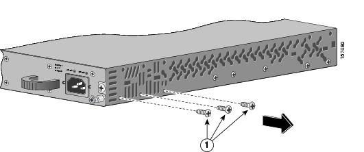
Figure 2-2 shows how to attach a bracket to one side of the RPS 2300 for installation into a 19-inch rack with the front panel or rear panel of the RPS 2300 facing forward.
Figure 2-2 Attaching Brackets for 19-Inch Racks

Mounting the RPS 2300 in a Rack
After you attach the brackets to the RPS 2300, use the four supplied number-12 Phillips machine screws to securely attach the brackets to the rack (Figure 2-3). Use the black Phillips machine screws to attach the cable guide to the left or right bracket.
Note If you are installing the RPS 2300 in a rack with a switch stack, install the RPS 2300 at the bottom of the rack. If necessary, allow one RU space between the RPS 2300 and the switch above to provide room for cabling.
Figure 2-3 Mounting the RPS 2300 in a Rack
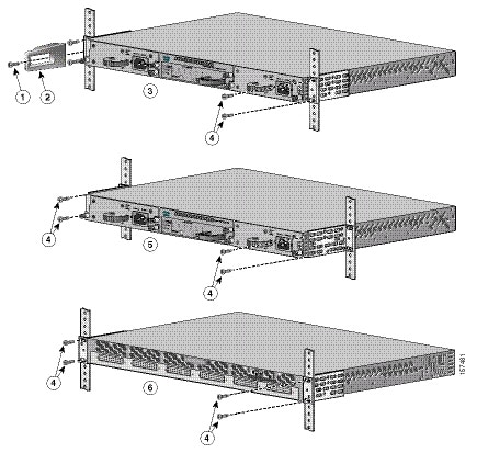
Table- or Shelf Mounting
To install the RPS 2300 on a table or shelf, locate the adhesive strip with the rubber feet in the mounting-kit envelope. Attach the four rubber feet to the recessed areas on the bottom of the chassis.
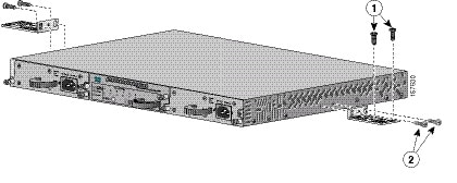
Remove two Phillips truss-head screws from the switch side panels, and use those screws to attach the brackets to the RPS 2300 (Figure 2-4). Secure the brackets to the table or shelf with the appropriate hardware.

Figure 2-4 Mounting the RPS 2300 on a Table or Shelf
Connecting the RPS 2300
This section provides instructions on connecting the RPS 2300 to a power source and to external devices. It includes these sections:
Cabling Options
The switches have different cabling options that you use to connect to the
RPS 2300. The RPS 2300 uses these connector cables:
- RPS cable for the Catalyst 3750-E and 3560-E switches (CAB-RPS-2300-E=): 22-pin connector on one end and 22-pin connector on the other end.
- RPS cable (CAB-RPS-2300=): 22-pin connector on one end and 14-pin connector on the other end. Use this cable to connect the RPS 2300 to all other supported Cisco devices.
For a complete list of products that the RPS 2300 supports, see the Cisco Redundant Power System 2300 Compatibility Matrix available on Cisco.com.
For more information about the RPS cables, see Appendix B, “Connector and Cable Specifications.”
Power Considerations
The switch connected to the RPS 2300 might restart when it changes from RPS power to its internal power. We recommend that you first divert switch traffic to an alternate switch to avoid data loss. This does not occur on the Catalyst 3750-E or Catalyst 3560-E switches.
Connecting the Cables
This section describes how to connect the cable and power supply modules to the RPS 2300.
(Optional) The RPS is shipped with a single ground lug for grounding the
RPS 2300. Use the ground screw to attach the single ground lug and wire assembly to the RPS 2300 rear panel. Torque the ground lug screw to 60 lbf-in. (960 ozf-in.).
Note In installations that require Network Equipment Building Systems (NEBS)-compliant grounding, use 10-AWG (6 mm2) copper wire.
Note If you are connecting another device to the RPS 2300, place the RPS port to be connected into standby mode. This prevents the device that the RPS 2300 is backing up from losing power.
Follow these steps to connect the cables:
Step 1 Connect the power cable to the power supply (Figure 2-7), and connect the other end of the power cable to an AC-power source.
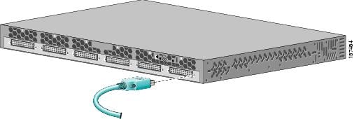
Step 2 Connect one end of the RPS cable to an RPS DC output connector (Figure 2-6).
Step 3 Connect the other end of the RPS cable to the RPS receptacle on the switch.
Step 4 Repeat through Step 3 for each switch that the RPS 2300 supports.
Step 5 Using a ratcheting torque screwdriver, torque each screw to 5 in-lbf. (80 ozf-in.).
To ensure proper operation, be sure that you completely seat the connector and that you securely tighten the screws.
Step 6 (Optional) Press the RPS Standby/Active button to put the RPS 2300 into active mode.
Step 7 The RPS LEDs and DC-output LEDs for the connected devices should be green. If they are not green, see Chapter1, “Troubleshooting”
Note To power off the RPS 2300, disconnect the AC-input power from the RPS 2300, and disconnect all connected DC port connector cables.
Figure 2-5 Connecting the Power Supply Modules to the RPS 2300
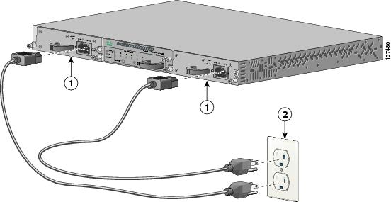
Figure 2-6 Connecting the Cable to the RPS 2300
 Feedback