|
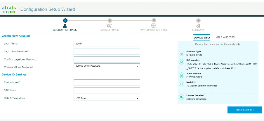
Hostname
|
The hostname or device name you provided as part of Quick Setup
|
The hostname or device name you provided as part of Quick Setup
|
The hostname or device name you provided as part of Quick Setup
|
|
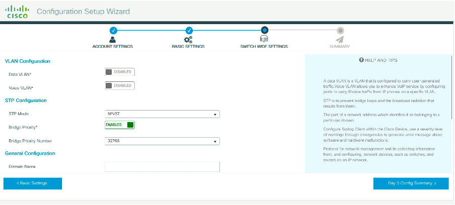
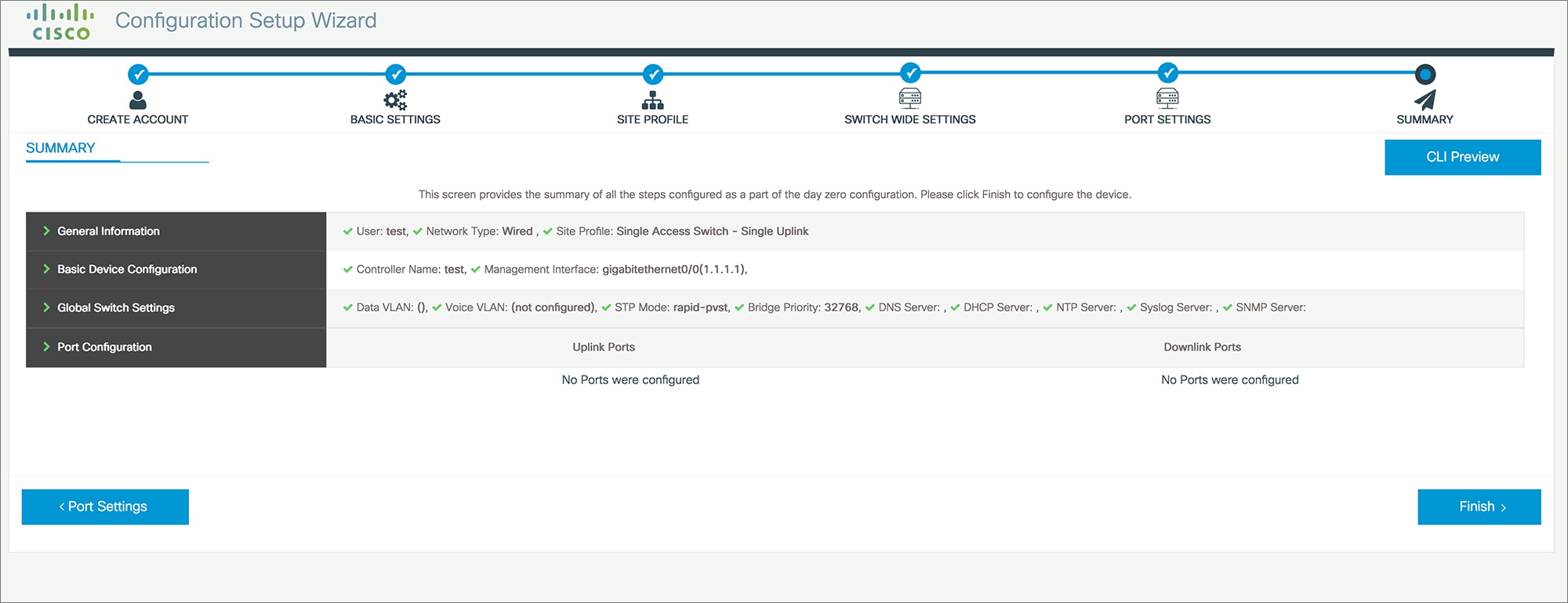
Spanning Tree Mode
|
RPVST+
|
RPVST+
|
RPVST+
|
|
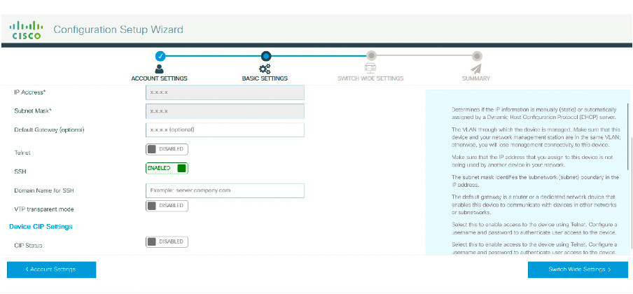
VTP
|
Mode Transparent
|
Mode Transparent
|
Mode Transparent
|
|
UDLD
|
Enabled
|
Enabled
|
Enabled
|
|
Error Disable Recovery
|
Recovery mode set to Auto
|
Recovery mode set to Auto
|
Recovery mode set to Auto
|
|
Port Channel Load Balance
|
Source Destination IP
|
Source Destination IP
|
Source Destination IP
|
|
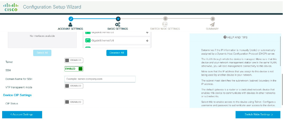
SSH
|
Version 2
|
Version 2
|
Version 2
|
|
SCP
|
Enabled
|
Enabled
|
Enabled
|
|
VTY Access to Switch
|
Enabled
|
Enabled
|
Enabled
|
|
Service Timestamp
|
Enabled
|
Enabled
|
Enabled
|
|
VLAN
|
The following VLANs are created:
-
Default VLAN
-
Data VLAN
-
Voice VLAN
-
Management VLAN
|
The following VLANs are created:
-
Default VLAN
-
Data VLAN
-
Voice VLAN
-
Management VLAN
|
The following VLANs are created:
-
Default VLAN
-
Data VLAN
-
Voice VLAN
-
Management VLAN
|
|
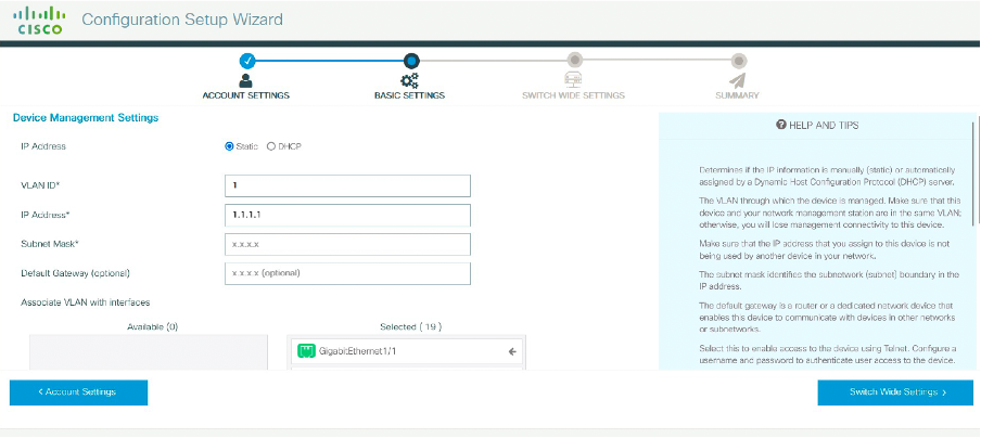
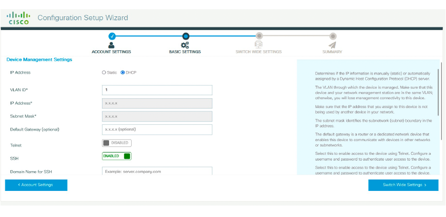
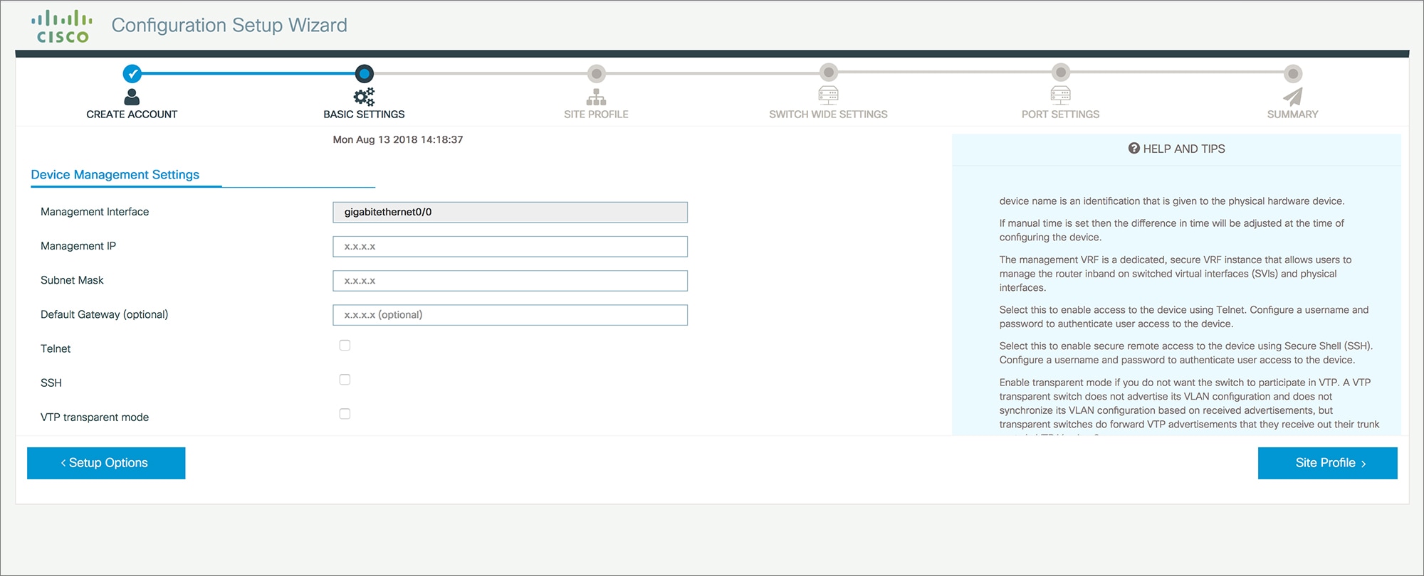
Management Interface
|
Layer 3 settings configured on the management port, based on Quick Setup
|
Layer 3 settings configured on the management port, based on Quick Setup
|
Layer 3 settings configured on the management port, based on Quick Setup
|
|
IPv6 Host Policy
|
IPv6 host policy created
|
IPv6 host policy created
|
IPv6 host policy created
|
|
QoS Policy for Downlink Ports
|
Auto QoS Policy for Access defined
|
Auto QoS Policy for Access defined
|
Auto QoS Policy for Access defined
|
|
QoS Policy for Uplink Ports
|
QoS Policy for Distribution created
|
QoS Policy for Distribution created
|
QoS Policy for Distribution created
|
|
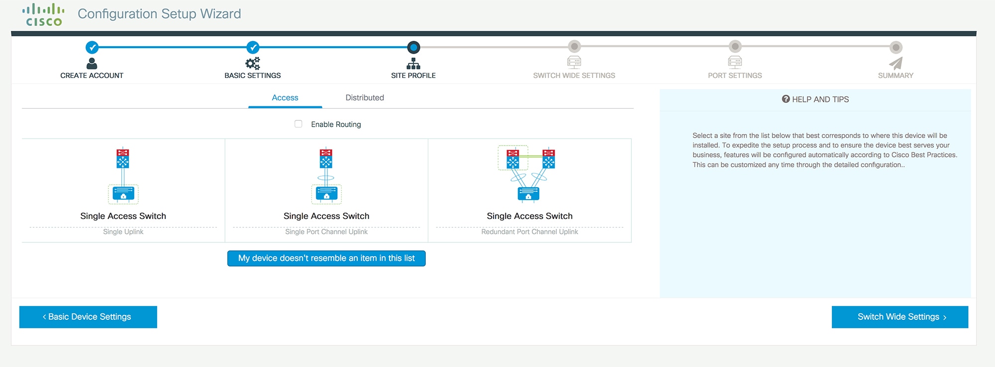
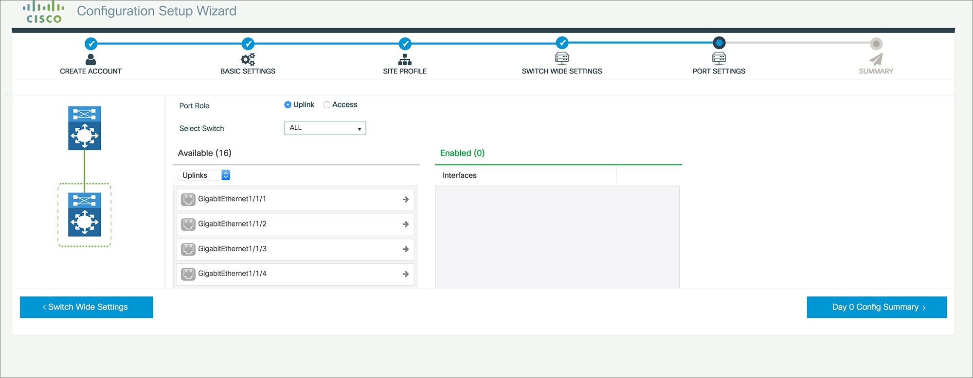
Uplink Interfaces
|
Selected uplink interfaces configured as trunk ports, set to allow all VLANs
|
Selected ports configured as Port-channel in trunk mode, set to allow all VLANs.
|
Selected ports configured as Port-channel in trunk mode, set to allow all VLANs.
|
|
Downlink Interfaces
|
Downlink ports configured in Access mode
|
Downlink ports configured in Access mode
|
Downlink ports configured in Access mode
|
|
Port-channel
|
Not configured
|
Port-channel to distribution created
|
Port-channel to distribution created
|
 Feedback