Product Overview
The Cisco® Industrial Ethernet (IE) 3X00 Rugged Series Switch is the latest addition to our ruggedized switching platforms and provides superior high-bandwidth switching and proven Cisco IOS® Software-based routing capabilities for industrial environments. The Catalyst IE3x00 Rugged Series delivers highly secure access and industry-leading convergence using the Cisco Resilient Ethernet Protocol (REP) and is built to withstand extreme environments while adhering to overall IT network design, compliance, and performance requirements.
The Catalyst IE3x00 Rugged Series Switch is ideal for industrial Ethernet applications where hardened products are required, including factory automation, energy and process control, intelligent transportation systems (ITS), oil and gas field sites, city surveillance programs, and mining. With improved overall performance, greater bandwidth, a richer feature set, and enhanced hardware, the Cisco Catalyst IE3x00 Rugged Series Switch complements the current industrial Ethernet portfolio of related Cisco industrial switches.
The Cisco Catalyst IE3x00 Rugged Series Switch can easily be installed in your network. Through a user-friendly web Web UI, the Cisco Catalyst IE3x00 Rugged Series Switch provides easy out-of-the-box configuration and simplified operational manageability to deliver advanced security, data, video, and voice services over industrial networks.
Switch Models
|
Default License Level1 |
Description |
|
|---|---|---|
|
IE-3200-8T2S-E |
Network Essentials |
8 Gigabit Ethernet 10/100/1000 RJ45 ports, 2 fiber 100/1000 SFP-based ports, non-PoE |
|
IE-3200-8P2S-E |
Network Essentials |
8 Gigabit Ethernet 10/100/1000 PoE/PoE+ ports, 2 fiber 100/1000 SFP-based ports; PoE power budget of 240W |
|
IE-3300-8T2S-E |
Network Essentials |
8 Gigabit Ethernet 10/100/1000 RJ45 ports, 2 fiber 100/1000 SFP-based ports, non-PoE |
|
IE-3300-8P2S-E |
Network Essentials |
8 Gigabit Ethernet 10/100/1000 PoE/PoE+ ports, 2 fiber 100/1000 SFP-based ports; PoE power budget of 360W (including expansion module) |
|
IE-3300-8T2S-A |
Network Advantage |
8 Gigabit Ethernet 10/100/1000 RJ45 ports, 2 fiber 100/1000 SFP-based ports, non-PoE |
|
IE-3300-8P2S-A |
Network Advantage |
8 Gigabit Ethernet 10/100/1000 PoE/PoE+ ports, 2 fiber 100/1000 SFP-based ports; PoE power budget of 360W (including expansion module) |
|
IE-3300-8T2X-A |
Network Advantage |
8 Gigabit Ethernet 10/100/1000 RJ45 ports, 2 fiber 1/10 Gigabit Ethernet SFP-based ports, non-PoE |
|
IE-3300-8T2X-E |
Network Essentials |
8 Gigabit Ethernet 10/100/1000 RJ45 ports, 2 fiber 1/10 Gigabit Ethernet SFP-based ports, non-PoE |
|
IE-3300-8U2X-A |
Network Advantage |
8 GE Copper (4PPoE) & 2 10G SFP, Mod |
|
IE-3300-8U2X-E |
Network Essentials |
8 GE Copper (4PPoE) & 2 10G SFP, Mod |
|
IE-3400-8T2S-E |
Network Essentials |
8 Gigabit Ethernet 10/100/1000 RJ45 ports, 2 fiber 100/1000 SFP-based ports, non-PoE |
|
IE-3400-8T2S-A |
Network Advantage |
8 Gigabit Ethernet 10/100/1000 RJ45 ports, 2 fiber 100/1000 SFP-based ports, non-PoE |
|
IE-3400-8P2S-E |
Network Essentials |
8 Gigabit Ethernet 10/100/1000 RJ45 ports, 2 fiber 100/1000 SFP-based ports with PoE |
|
IE-3400-8P2S-A |
Network Advantage |
8 Gigabit Ethernet 10/100/1000 RJ45 ports, 2 fiber 100/1000 SFP-based ports with PoE |
|
IEM-3300-4MU= |
N/A |
Expansion Module with 4 2.5G Copper (4PPoE) |
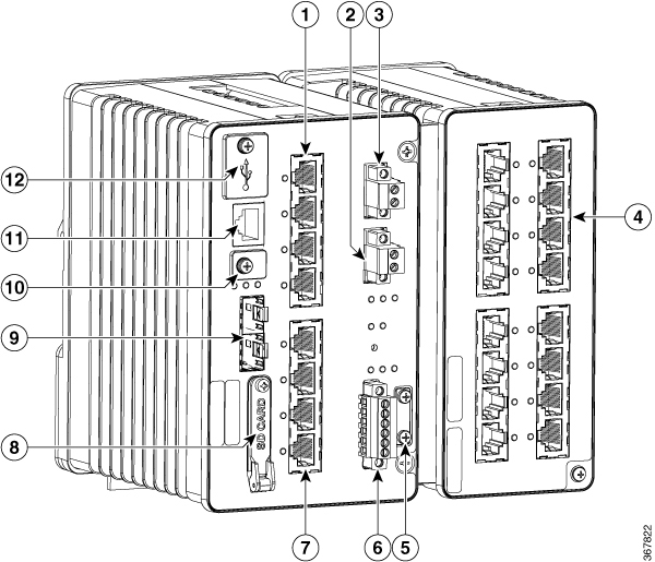
Front Panel Overview
The illustrations in this section provide an overview of the variety of components available on the various switch models in this product family. Not all models are illustrated.
|
1 |
10/100/1000 Copper Ethernet ports (downlink ports) |
7 |
10/100/1000 Copper Ethernet ports (downlink ports) |
|
2 |
Power connector DC-B |
8 |
Flash memory card slot |
|
3 |
Power connector DC-A |
9 |
SFP module slots (uplink ports) |
|
4 |
10/100/1000 Copper Ethernet ports (downlink ports) |
10 |
USB mini-Type B (console) port2 |
|
5 |
Protective ground connection |
11 |
RJ-45 console port |
|
6 |
Alarm connector |
12 |
USB mini-Type A port3 |
Ports
Note: Different configurations are available. Not all ports or slots are present in all configurations.
1G SFP/ 10G SFP+ Ports (Uplinks)
Depending on the switch model, the uplink ports either support 1G/100M optics or 10G/1G optics. When using a 10G SFP, the port only operates at 1Gbps/10Gbps.
The IEEE 802.3u SFP module uplink slots provide full-duplex100/1000 Mb/s and 10Gb connectivity over multi-mode (MM) fiber cables or single-mode (SM) fiber cables. These ports use a SFP fiber-optic transceiver module that accepts a dual LC connector. Check the SFP specifications for the cable type and length.
For more information about SFP/SFP+ modules and cables, see Transceiver Modules.
10/100/1000 BASE-T Downlink Ports
You can set the 10/100/1000 Base-T ports to operate in 10, 100 or 1000 Mb/s in full-duplex or half-duplex mode. You can also set these ports for speed and duplex autonegotiation in compliance with IEEE 802.3. (The default setting is autonegotiate.) When set for autonegotiation, the port senses the speed and duplex settings of the attached device and advertises its own capabilities. If the connected device also supports autonegotiation, the switch port negotiates the best connection (that is, the fastest line speed that both devices support, and full-duplex transmission if the attached device supports it) and configures itself accordingly. In all cases, the attached device must be within 328 feet (100 meters). 100BASE-TX traffic requires Category 5 cable. 10BASE-T traffic can use Category 3 or Category 4 cables.
You can use the mdix auto interface configuration command in the command-line interface (CLI) to enable the automatic medium-dependent interface crossover (auto-MDIX) feature. When the auto-MDIX feature is enabled, the switch detects the required cable type for copper Ethernet connections and configures the interfaces accordingly. For configuration information for this feature, see the switch software configuration guide or the switch command reference.
2500 BASE-T Downlink Ports
The 2500base-T ports operate in 100 Mb, 1000 Mb or 2500 Mb mode instead of 10,100, 1000. You can also set these ports for speed and duplex autonegotiation in compliance with IEEE 802.3. (The default setting is autonegotiate.) When set for autonegotiation, the port senses the speed and duplex settings of the attached device and advertises its own capabilities. If the connected device also supports autonegotiation, the switch port negotiates the best connection (that is, the fastest line speed that both devices support, and full-duplex transmission if the attached device supports it) and configures itself accordingly. In all cases, the attached device must be within 328 feet (100 meters). Multigig downlinks require Category 5e cables. 100BASE-TX traffic requires Category 5 cable. 10BASE-T traffic can use Category 3 or Category 4 cables.
You can use the mdix auto interface configuration command in the command-line interface (CLI) to enable the automatic medium-dependent interface crossover (auto-MDIX) feature. When the auto-MDIX feature is enabled, the switch detects the required cable type for copper Ethernet connections and configures the interfaces accordingly. For configuration information for this feature, see the switch software configuration guide or the switch command reference.
100/1000 Mb/s SFP Module Downlink Ports (on expansion modules only)
Expansion modules that support SFP interfaces support 100Mb and 1000Mb SFP speeds.
The 100/1000 Mb/s SFP module downlink slots provide full-duplex 100/1000 Mb/s connectivity over multi-mode (MM) fiber cables or single-mode (SM) fiber cables. These ports use a SFP fiber-optic transceiver module that accepts a dual LC connector. Check the SFP specifications for the cable type and length.
Management Ports
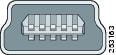
You can connect the switch to a PC running Microsoft Windows or to a terminal server through either the RJ-45 console port or the USB mini-Type B console port, also referred to as the USB-mini console port. These ports use the following connectors:
-
RJ-45 console port uses an RJ-45-to-DB-9 female cable.
-
USB-mini console port (5-pin connector) uses a USB Type A-to-5-pin mini-Type B cable.
The USB-mini console interface speeds are the same as the RJ-45 console interface speeds.
To use the USB-mini console port, you must install the Windows USB device driver on the device that is connected to the USB-mini console port and that is running Microsoft Windows.
With the Windows USB device driver, connecting and disconnecting the USB cable from the console port does not affect Windows HyperTerminal operations. Mac OS X or Linux require no special drivers.
The configurable inactivity timeout reactivates the RJ-45 console port if the USB-mini console port is activated, but no input activity occurs for a specified time period. When the USB-mini console port deactivates due to a timeout, you can restore its operation by disconnecting and reconnecting the USB cable. For information on using the CLI to configure the USB-mini console interface, see the switch software guide.
Power Connectors
DC Power Connector
You connect the DC power to the switch through the front panel connectors. The switch has a dual-feed DC power supply; two connectors provide primary and secondary DC power (DC-A and DC-B). The DC power connectors are near the top right of the Front Panel Overview on page 2 . Each power connector has an LED status indicator.
The switch power connectors are attached to the switch chassis. Each power connector has screw terminals for terminating the DC power. All connectors are attached to the switch front panel with the provided captive screws.
The power connector labeling is on the panel. The positive DC power connection is labeled “+” , and the return connection is labeled “–” .
The switch can operate with a single power source or with dual power sources. When both power sources are operational, the switch draws power from the DC source with the higher voltage. If one of the two power sources fail, the other continues to power the switch.
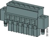
Alarm Connector
You connect the alarm signals to the switch through the alarm connector. The switch supports two alarm inputs and one alarm output relay. The alarm connector is on the bottom right of the front panel. See Front Panel Overview.
The alarm connector provides six alarm wire connections. The connector is attached to the switch front panel with the provided captive screws.
Both alarm input circuits can sense if the alarm input is open or closed. The alarm inputs can be activated for environmental, power supply, and port status alarm conditions. From the CLI, you can configure each alarm input as an open or closed contact.
The alarm output circuit is a relay with a normally open and a normally closed contact. The switch is configured to detect faults that are used to energize the relay coil and change the state on both of the relay contacts: normally open contacts close, and normally closed contacts open. The alarm output relay can be used to control an external alarm device, such as a bell or a light.
See the switch software configuration guide for instructions on configuring the alarm relays.
SFP Modules Supported
The SFP modules are switch Ethernet SFP modules that provide connections to other devices. Depending on the switch model, these field-replaceable transceiver modules provide uplink or downlink interfaces. The modules have LC connectors for fiber-optic connections.
Refer to the Cisco Optics-to-Device Compatibility Matrix for details about the supported SFP Modules.
LEDs
You can use the LEDs to monitor the switch status, activity, and performance.

|
1 |
SFP uplink 2 LED |
8 |
Alarm Output LED |
|
2 |
10/100/1000 Copper Ethernet Downlink Port LEDs on Base Chassis Ports 3-6 |
9 |
Alarm Input LED 2 |
|
3 |
DC Input A Status LED |
10 |
Alarm Input LED 1 |
|
4 |
DC Input B Status LED |
11 |
10/100/1000 Copper Ethernet Downlink Port LEDs on Base Chassis Ports 7-10 |
|
5 |
POE Operation LED (POE enabled versions) |
12 |
Express Setup LED and Button |
|
6 |
10/100/1000 Copper Ethernet Downlink Port LEDs on Expansion Module (If applicable) |
13 |
Console LED |
|
7 |
Operational Status LED |
14 |
SFP Uplink 1 LED |
Express Setup LED
The Express Setup LED displays the express setup mode for the initial configuration.
|
Color |
Setup Status |
|---|---|
|
Off (dark) |
Switch is configured as a managed switch. |
|
Solid green |
Switch is operating normally. |
|
Blinking green |
Switch is in initial setup, in recovery, or initial setup is incomplete. |
|
Solid red |
Switch failed to start initial setup or recovery because there is no available switch port to which to connect the management station. Disconnect a device from a switch port, and then press the Express Setup button. |
System LED
The System LED shows whether the system is receiving power and is functioning properly.
|
Color |
System Status |
|---|---|
|
Off |
System is not powered on. |
|
Blinking green |
Boot is in progress. |
|
Green |
System is operating normally. |
|
Red |
Switch is not functioning properly. |
USB-Mini Console LED
The USB-mini console LED shows which console port is in use. See LEDs for the LED location. If you connect a cable to a console port, the switch automatically uses that port for console communication. If you connect two console cables, the USB-mini console port has priority.
|
Color |
Description |
|---|---|
|
Green |
USB-mini console port is active. RJ-45 console port LED is not active. |
|
Off |
Port is not active. RJ-45 console port is active. |
Alarm LEDs
Alarm OUT
Alarm Output LED is set based on severity of input/facility Alarm
|
Color |
System Status |
|---|---|
|
Off |
Alarm OUT is not configured, or the switch is off. |
|
Green |
Alarm OUT is configured, no Alarm detected or Input Alarm detected with severity NONE. |
|
Blinking red |
Input/Facility Alarm detected with severity Major. |
|
Red |
Input/Facility Alarm detected with severity Minor. |
Alarm IN1 and IN2
|
Color |
System Status |
|---|---|
|
Off |
Alarm IN1 or IN2 not configured. |
|
Green |
Alarm IN1 or IN2 configured, no alarm detected. |
|
Blinking red |
Major alarm detected. |
|
Red |
Minor alarm detected. |
Power Status LEDs
The switch can operate with one or two DC power sources. Each DC input has an associated LED that shows the status of the corresponding DC input. If power is present on the circuit, the LED is green. If power is not present, the LED color depends on the alarm configuration. If alarms are configured, the LED is red when power is not present; otherwise, the LED is off.
If the switch has dual power sources, the switch draws power from the power source with the higher voltage. If one of the DC sources fails, the alternate DC source powers the switch, and the corresponding power status LED is green. The power status for the failed DC source is either off or red, depending on the alarm configuration.
|
Color |
System Status |
|---|---|
|
Green |
Power is present on the associated circuit, system is operating normally. |
|
Off |
Power is not present on the circuit, or the system is not powered up. |
|
Red |
Power is not present on the associated circuit, and the power supply alarm is configured. |
The Power A and Power B LEDs show that power is not present on the switch if the power input drops below the low valid level. The power status LEDs only show that power is present if the voltage at the switch input exceeds the valid level.
For information about the power LED colors during the boot fast sequence, see Verifying Switch Operations section of this document.
Port Status LEDs
Each port and SFP uplink slot has a status LED, as shown in LEDs and described below.
|
Color |
System Status |
|---|---|
|
Off |
No link. |
|
Solid green |
Link present. |
|
Blinking green |
Activity. Port is sending or receiving data. |
|
Alternating green-amber |
Link fault. Error frames can affect connectivity, and errors such as excessive collisions, CRC errors, and alignment and jabber errors are monitored for a link-fault indication. |
|
Solid amber |
Port is not forwarding. The port was disabled by management, an address violation, or STP. After a port is reconfigured, the port LED can remain amber for up to 30 seconds while STP checks the switch for possible loops. |
PoE Status LED
The PoE STATUS LEDs are located on the front panel, next to the PoE ports (models equipped with PoE ports).The LEDs display the functionality and status of the adjacent PoE ports.
|
Color |
PoE Status |
||
|---|---|---|---|
|
Off |
PoE is off. If the powered device is receiving power from a non-PoE power source, the port LED is off even if the powered device is connected to the switch port. |
||
|
Green |
PoE is on. The port LED is green only when the PoE port is providing power. |
||
|
Alternating green and amber |
PoE is denied because providing power to the powered device will exceed the switch power capacity. |
||
|
Flashing amber |
PoE is off due to a fault.
|
||
|
Amber |
PoE for the port is disabled. (PoE is enabled by default.) |
Flash Memory Card
The switch supports a flash memory card that makes it possible to replace a failed switch without reconfiguring the new switch. The slot for the flash memory card is on the front of the switch. A cover protects the flash card and holds the card firmly in place. The cover is hinged and closed with a captive screw. This prevents the card from coming loose and protects against shock and vibration.
Note: For more information on inserting and removing the flash memory card, see Installing or Removing the Flash Memory Card (Optional).
Note: The replacement SD card part number is SD-IE-4GB.
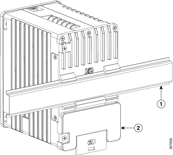
Rear Panel
The rear panel of the switch has a latch for installation on a DIN rail. The latch is spring-loaded to move down to position the switch over a DIN rail and return to the original position to secure the switch to a DIN rail.
 Note |
The switch should only be installed in the vertical orientation shown in this document. |
Management Options
The switch supports these management options:
-
Web UI
You can use Web UI, which is in the switch memory, to manage individual and standalone switches. This web interface offers quick configuration and monitoring. You can access Web UI from anywhere in your network through a web browser. For more information, see the Web UI online help. -
Cisco IOS CLI
The switch CLI is based on Cisco IOS software and is enhanced to support desktop-switching features. You can fully configure and monitor the switch. You can access the CLI either by connecting your management station directly to the switch management port, or a console port, or by using Telnet from a remote management station. See the switch command reference on Cisco.com for more information. -
SNMP network management
You can manage switches from a SNMP-compatible management station that is running platforms such as HP OpenView or SunNet Manager. The switch supports a comprehensive set of Management Information Base (MIB) extensions and four Remote Monitoring (RMON) groups. See the switch software configuration guide on Cisco.com and the documentation that came with your SNMP application for more information. -
Common Industrial Protocol
The Common Industrial Protocol (CIP) management objects are supported. The Cisco IE 3X00 can be managed by CIP-based management tools, allowing the user to manage an entire industrial automation system with one tool. -
TIA Portal
-
TCP/IP and RT
This switch supports PROFINET TCP/IP and RT and can be managed by Siemens' automation software such as STEP 7 and TIA Portal.
-
 Feedback