
Cisco C9350 Series Smart Switches - Technical Specifications
Environmental and physical specifications
Environmental specifications
This section describes the environmental specifications for the Cisco C9350 switch models and power supply modules.
|
Environmental ranges |
|
|---|---|
|
Operating temperature 1 |
|
|
Storage temperature |
–40 to 167°F (–40 to 75°C) |
|
Relative humidity |
10 to 95% (non-condensing) |
|
Operating altitude |
Up to 10,000 ft (3,000 m) |
|
Storage altitude |
Up to 15,000 ft (4,500 m) |
|
Environmental ranges |
|
|---|---|
|
Operating temperature |
23°F to 113°F (–5°C to 45°C) up to 5,000 feet (1,500m) 23°F to 104°F (–5°C to 40ºC) up to 10,000 feet (3,000m) |
|
Storage temperature |
–40 to 167°F (–40 to 75°C) |
|
Relative humidity |
10 to 95% (non-condensing) |
|
Altitude |
10,000 ft (3,000 m) up to 40°C |
Physical specifications of the switch
This section describes the dimensions and weight of the switch models and power supply modules.
This table describes the physical specifications with the FAN FRUs and the power supplies installed.
|
Switch PID |
Dimensions (H x W x D) in inches and centimeter |
Weight (with the default power supply unit) |
|---|---|---|
|
C9350-48HX |
1.73 x 17.5 x 18.6 in (4.4 x 44.5 x 47.2 cm) |
18.73 lb (8.5 kg) |
|
C9350-24P |
1.73 x 17.5 x 15.1 in (4.4 x 44.5 x 38.3 cm) |
13.54 lb (6.14 kg) |
|
C9350-48P |
1.73 x 17.5 x 15.1 in (4.4 x 44.5 x 38.3 cm) |
13.54 lb (6.14 kg) |
|
C9350-24T |
1.73 x 17.5 x 15.1 in (4.4 x 44.5 x 38.3 cm) |
13.8 lb (6.26 kg) |
|
C9350-48T |
1.73 x 17.5 x 15.1 in (4.4 x 44.5 x 38.3 cm) |
13.8 lb(6.26kg) |
|
C9350-48TX |
1.73 x 17.5 x 18.6 in (4.4 x 44.5 x 47.2 cm) |
17.7 lb (8 kg) |
|
C9350-24U |
1.73 x 17.5 x 15.1 in (4.4 x 44.5 x 38.3 cm) |
13.94 lb( 6.35 kg) |
|
C9350-48U |
1.73 x 17.5 x 15.1 in (4.4 x 44.5 x 38.3 cm) |
14.14 lb( 6.42 kg) |
Physical specifications of power supply modules
The dimensions shown include the extraction handle and the keying feature.
|
Power supply module |
Weight |
Dimensions (H x D x W) |
|
PWR-C2-1600WAC |
2.425 lb (1.09 kg) |
2.18 x 1.57 x 11.81 in (5.55 x 4 x 30 cm) |
|
PWR-C2-850WAC |
1.54 lb (0.69 kg) |
2.18 x 1.57 x 8.66 in (5.55 x 4 x 22 cm) |
|
PWR-C2-500WAC |
1.2 lb (0.54 kg) |
2.18 x 1.57 x 8.66 in (5.55 x 4 x 22 cm) |
Specifications for the power supplies and fans
|
Specification |
Power supply |
||
|---|---|---|---|
|
PWR-C2-1600WAC |
PWR-C2-850WAC |
PWR-C2-500WAC |
|
|
Maximum output power |
|
850 W |
500 W |
|
Input voltage and frequency |
|
90 V to 264 V, 47 to 63 Hz |
90 V to 264 V, 47 to 63 Hz |
|
Input current |
12.5 A (maximum) | 10 A (maximum) |
6 A (maximum) |
|
Output ratings |
|
15.18 A (maximum) |
8.93 A (maximum) |
|
Total output BTU |
|
2900 BTUs per hour |
1706 BTU per hour |
|
Environmental ranges |
|
|
Operating temperature |
23 to 176°F (–5 to 80°C) |
|
Storage temperature |
–40 to 185°F (–40 to 85°C) up to 15,000 ft (4500 m) |
|
Relative humidity |
5 to 95% (non-condensing) |
|
Altitude |
Up to 13,000 ft (4000 m) |
|
Physical specification |
|
|
Dimensions (H x D x W) |
1.62 x 1.73 x 4.24 in. (4.11 x 4.39 x 10.76 cm) |
|
Weight (for three fans) |
0.48 lb (0.21 kg) |
|
Operating specification |
|
|
Airflow |
20 cfm |
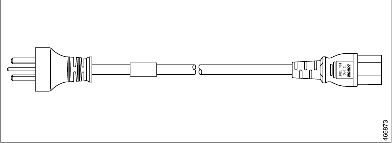
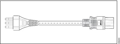
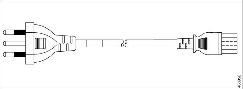
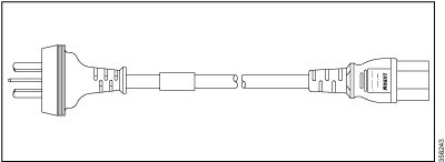
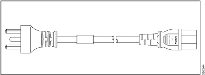
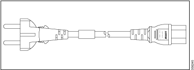
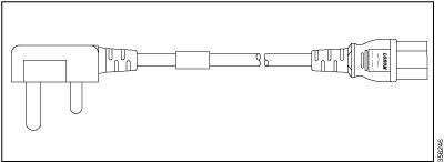
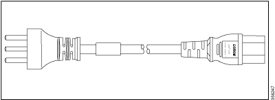
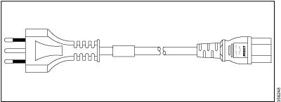
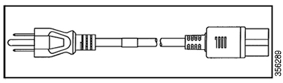
AC power cord specifications
This table lists the specifications for the AC power cords that are supported for the 500 W and 850 W AC-input power supplies supported with Cisco C9350 series smart switches.
|
Locale |
Part number |
Cordset rating |
Length |
Power cord |
|---|---|---|---|---|
|
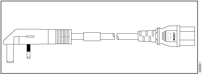
Argentina |
CAB-TA-AR |
250 VAC, 10 A |
2.5 m |
|
|
Australia |
CAB-TA-AP |
250 VAC, 10 A |
2.5 m |
|
|
Brazil |
CAB-ACBZ-12A |
125 VAC, 12 A |
2.5 m |
 |
|
Brazil |
CAB-ACBZ-10A |
250 VAC, 10 A |
2.5 m |
|
|
China |
CAB-TA-CN |
250 VAC, 10 A |
2.5 m |
 |
|
Denmark |
CAB-TA-DN |
250 VAC, 10 A |
2.5 m |
 |
|
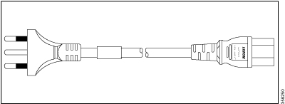
Europe |
CAB-TA-EU |
250 VAC, 10 A |
2.5 m |
 |
|
India |
CAB-TA-IN |
250 VAC, 10 A |
2.5 m |
 |
|
Israel |
CAB-TA-IS |
250 VAC, 16 A |
2.5 m |
 |
|
Italy |
CAB-TA-IT |
250 VAC, 10 A |
2.5 m |
 |
|
Japan |
CAB-TA-JP |
125 VAC, 12 A |
2.5 m |
 |
|
Japan |
CAB-TA-250V-JP |
250 VAC, 12 A |
2.5 m |
|
|
Japan |
CAB-C15-CBN-JP |
250 VAC, 12 A |
3.05 m |
 |
|
Korea |
CAB-AC -C15-KOR |
250 VAC, 10 A |
2.5 m |
- |
|
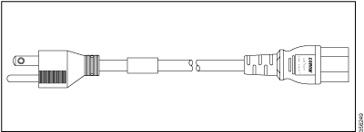
North America |
CAB-TA-NA |
125 VAC, 15 A |
2.5 m |
 |
|
Switzerland |
CAB-TA-SW |
250 VAC, 10 A |
2.5 m |
 |
|
Taiwan |
CAB-AC-C15-TW |
125 VAC, 15 A |
2.5 m |
- |
|
United Kingdom |
CAB-TA-UK |
250 VAC, 10 A |
2.5 m |
 |
|
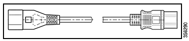
Cabinet jumper power cord, C14-C15 connectors |
CAB-C15-CBN |
250 VAC, 13 A |
1.22 m |
|
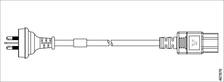
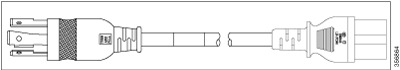
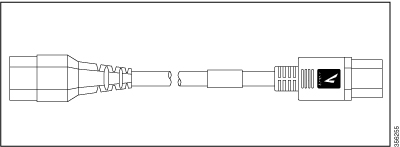
AC power cords for 1600 W PSUs
This table lists the specifications for the AC power cords that are supported with the 1600 W power supply units.
|
Locale |
Part number |
Cordset rating |
length |
|---|---|---|---|
|
Argentina |
C9K-PWR-CAB-AC-AR |
250 VAC, 16 A |
4.25 m |
|
Australia |
C9K-PWR-CAB-AC-AU |
250 VAC, 16 A |
4.25 m |
|
China |
C9K-PWR-CAB-AC-CN |
250 VAC, 16 A |
4.25 m |
|
Europe |
C9K-PWR-CAB-AC-EU |
250 VAC, 16 A |
4.25 m |
|
India |
C9K-PWR-CAB-AC-IN |
250 VAC, 16 A |
4.25 m |
|
Israel |
C9K-PWR-CAB-AC-IS |
250 VAC, 16 A |
4.25 m |
|
Italy |
C9K-PWR-CAB-AC-IT |
250 VAC, 16 A |
4.25 m |
|
Japan |
C9K-PWR-CAB-AC-JP |
250 VAC, 20 A |
4.25 m |
|
Japan and North America |
CAB-L620P-C13-JPN |
250 VAC, 15A |
2.5 m |
|
North America |
C9K-CAB-US520PC21 |
125 VAC, 20 A |
2.5 m |
|
North America |
C9K-PWR-CAB-AC-US |
250 VAC, 20 A |
4.25 m |
|
South Africa |
C9K-PWR-CAB-AC-SA |
250 VAC, 16 A |
4.25 m |
|
United Kingdom |
C9K-PWR-CAB-AC-UK |
250 VAC, 16 A |
4.25 m |
|
North America |
C9K-PWR-CAB-AC-BL (Cabinet jumper power cord) |
250 VAC, 20 A |
4.25 m |
StackWise accessories
All Cisco stack cables are halogen-free. The StackWise cables of lengths 0.5 m, 1 m, and 3 m supported. You can order the stacking cables from your Cisco sales representative.
|
Product ID |
Product description |
|---|---|
|
STACK-T1A-50CM |
50 cm stacking cable for Cisco StackWise |
|
STACK-T1A-1M |
1 m stacking cable for Cisco StackWise |
|
STACK-T1A-3M |
3 m stacking cable for Cisco StackWise |
|
Cable part number |
Cable length |
Minimum bend radius |
Minimum coiled diameter |
|---|---|---|---|
|
STACK-T1A-50CM |
1.64 feet (0.5 m) |
1.6 in. (41 mm) |
Not applicable |
|
STACK-T1A-1M |
3.28 feet (1.0 m) |
1.6 in. (41 mm) |
5.2 in. (132 mm) |
|
STACK-T1A-3M |
9.84 feet (3.0 m) |
3.2 in. (82 mm) |
7.17 in. (182 mm) |
- With a 0.5 m cable, the minimum coiled diameter is negligible and the cable cannot be physically coiled without exceeding the bending limit.
StackPower accessories
All Cisco stack cables are halogen-free. The StackPower cables of lengths 0.35 m and 1 m are supported on Cisco C9350 switches. You can order the stacking cables from your Cisco sales representative.
|
Product ID |
Product description |
|---|---|
|
CAB-SPWR-35CM |
35 cm cable for Cisco StackPower |
|
CAB-SPWR-100CM |
1 m cable for Cisco StackPower |
Transceiver module network cables
For transceiver cabling specifications, refer to these documents:
- Cisco SFP and SFP+ Transceiver Module Installation Notes
- Cisco 40-Gigabit QSFP+ Transceiver Modules Installation Note
Each port must match the wavelength specifications on the other end of the cable, and the cable must not exceed the stipulated cable length. Copper 1000BASE-T SFP module transceivers use standard four twisted-pair, Category 5 cable at lengths up to 328 feet (100 meters).
Connectors
This section describes the connectors supported by Cisco C9350 series smart switches.
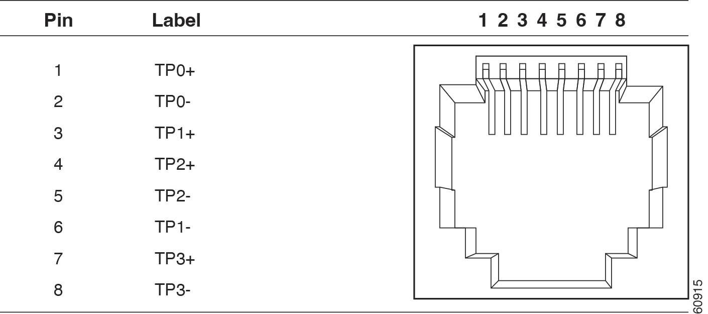
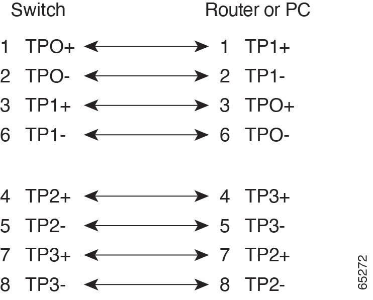
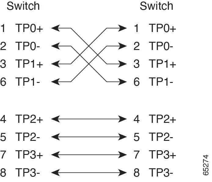
10/100/1000 Ports
This illustrations shows all 10/100/1000 ports including the PoE ports that use standard RJ-45 connectors and Ethernet pinouts
Module connectors
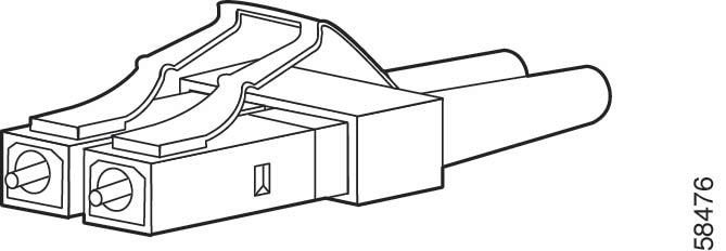
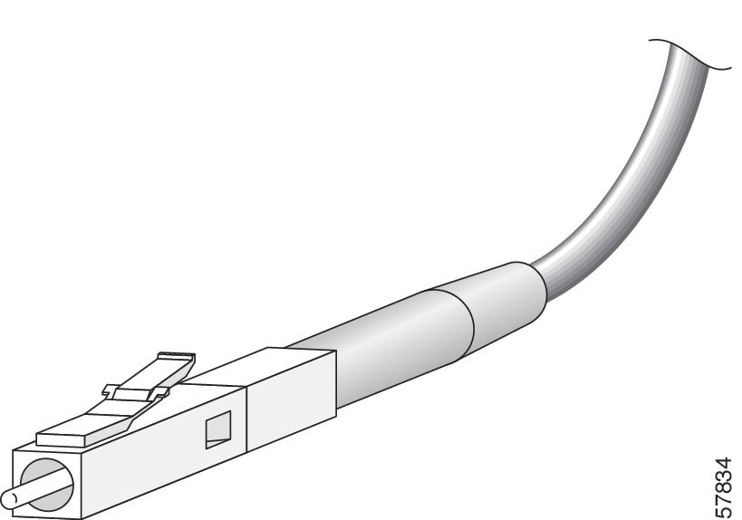
MPO-12 connectors
The multi-fiber push on (MPO) connector is used in high-density fiber optic networks. An MPO-12 connector has 12 fiber strands in a single connector that enables high-speed data transmission and efficient cable management. Its footprint is similar to the SC simplex connector. The MPO connector conforms to the TIA/EIA-604-5 intermateability standard. It is used for establishing 40G and 100G optical parallel connections.
The MPO connector conforms to the TIA/EIA-604-5 intermateability standard. It is used for establishing 40G and 100G optical parallel connections.
Key characteristics of MPO-12 connectors include
- compatibility with various transceivers: Many Cisco transceivers use MPO-12 connectors for data transmission.
- breakout cable support: MPO-12 connectors can be used in breakout cables.

Cable pinouts
A cable pinout refers to the specific arrangement of wires within a cable connector. Pinouts define how each pin is connected between the two ends of a cable.
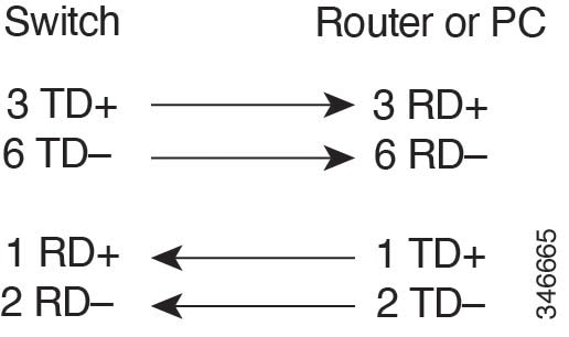
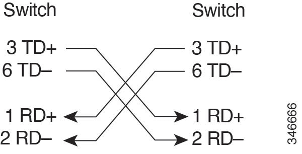
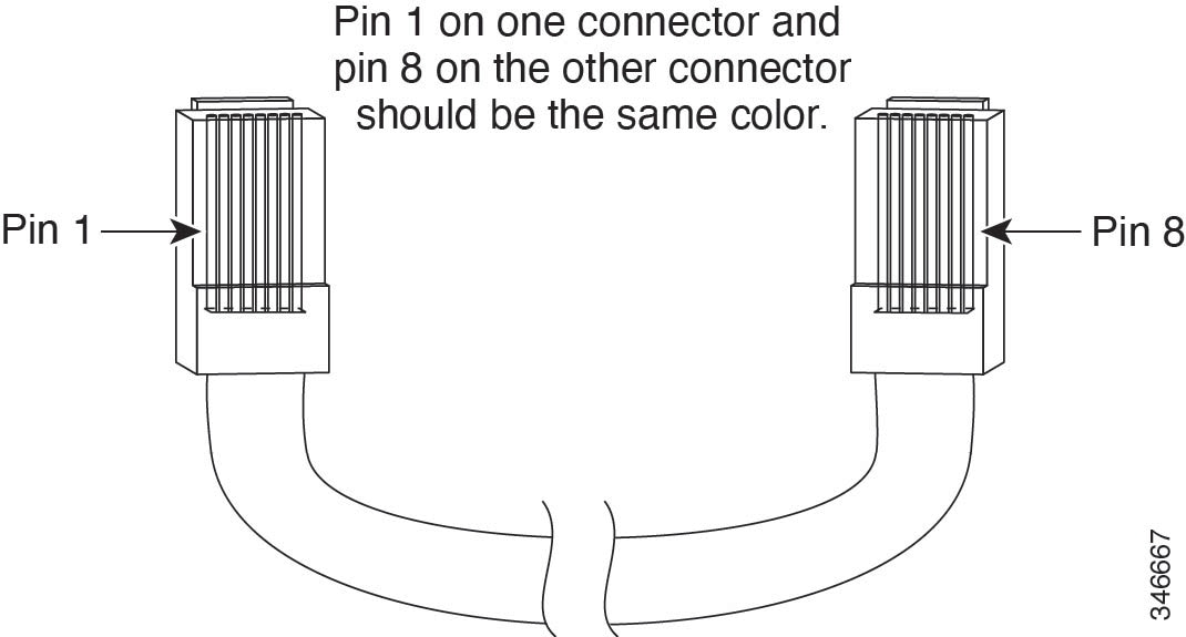
Identifying a crossover cable
Console port adapter pinouts
Use an RJ-45-to-DB-9 adapter cable to connect the switch console port to a console PC. You need to provide a RJ-45-to-DB-25 female DTE adapter to connect the switch console port to a terminal.
|
Switch console port (DTE) |
RJ-45-to-DB-9 terminal adapter |
Console device |
|---|---|---|
|
Signal |
DB-9 Pin |
Signal |
|
TxD |
2 |
RxD |
|
GND |
5 |
GND |
|
GND |
5 |
GND |
|
RxD |
3 |
TxD |
|
Switch console port (DTE) |
RJ-45-to-DB-25 terminal adapter |
Console device |
|---|---|---|
|
Signal |
DB-25 pin |
Signal |
|
TxD |
3 |
RxD |
|
GND |
7 |
GND |
|
GND |
7 |
GND |
|
RxD |
2 |
TxD |