
Cisco C9350 Series Smart Switches - Install the Switch
Install Cisco C9350
You can either rack mount the Cisco C9350 series smart switches or install the switch on a shelf or table. This section describes both these methods.
Rack mount the switch
Installation in racks other than 19-inch racks requires a bracket kit that is not shipped with the switch. You must order this bracket kit separately.
 Warning
Statement 1006—Chassis Warning for Rack-Mounting and Servicing
To prevent bodily injury when mounting or servicing this unit in a rack, you must take special precautions to ensure that the system remains stable. The following guidelines are provided to ensure your safety:
- This unit should be mounted at the bottom of the rack if it is the only unit in the rack.
- When mounting this unit in a partially filled rack, load the rack from the bottom to the top with the heaviest component at the bottom of the rack.
- If the rack is provided with stabilizing devices, install the stabilizers before mounting or servicing the unit in the rack.
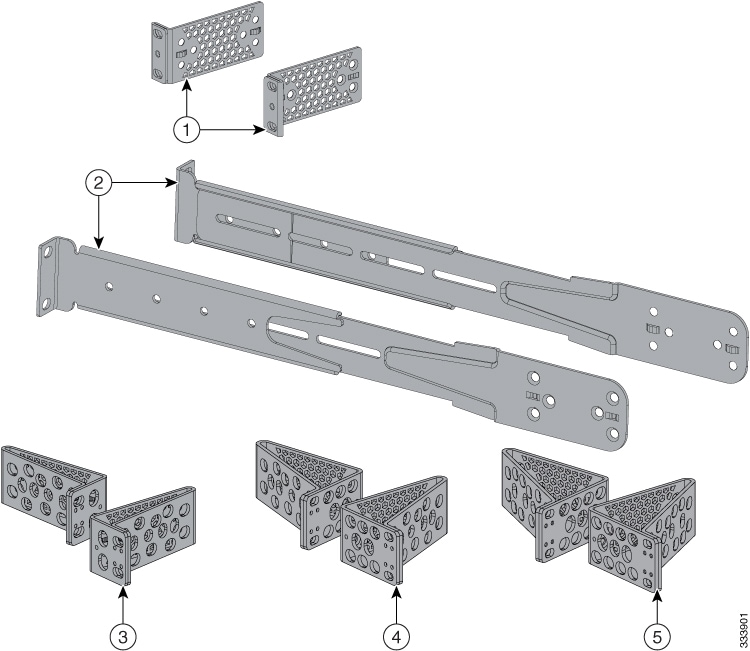
This figure shows the standard 19-inch brackets and other optional mounting brackets. You can order the optional brackets from your Cisco sales representative.
|
1 |
19-inch brackets (ACC-KIT-T1=) |
4 |
23-inch brackets (RACK-KIT-T1=) |
|
2 |
Extension rails and 5 brackets for four-point mounting, includes 19-inch brackets (4PT-KIT-T2=) |
5 |
24-inch brackets (RACK-KIT-T1=) |
|
3 |
ETSI brackets (RACK-KIT-T1=) |
- |
- |
Attach the rack mount brackets
Before you begin
Use two Phillips flat-head screws to attach the long side of the bracket to each side of the switch for the front or rear mounting positions. 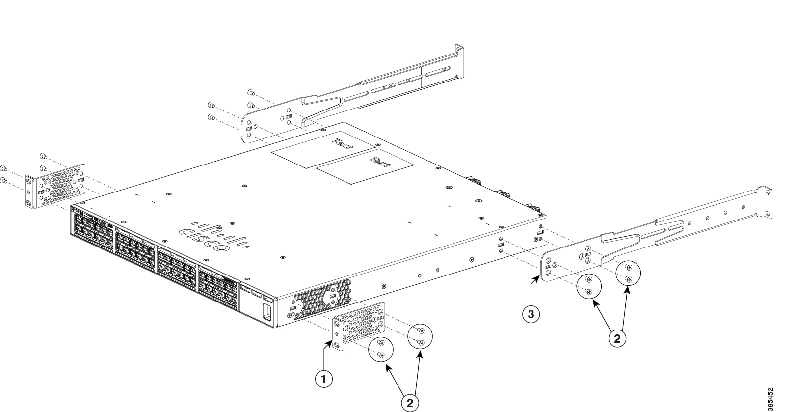
|
Mount the switch in a rack
Step 1 | Use the four supplied Phillips machine screws to attach the brackets to the rack. |
Step 2 | Use the black Phillips machine screw to attach the cable guide to the left or right bracket. You can do front-mounting, rear-mounting, mid-mounting, or four-point mounting of the switch. |
Install the switch on a table or shelf
Step 1 | To install the switch on a table or shelf, locate the adhesive strip with the rubber feet in the mounting-kit envelope. |
Step 2 | Attach the four rubber feet to the four circular etches on the bottom of the chassis. |
Step 3 | Place the switch on the table or shelf near an AC power source. |
Step 4 | When you complete the switch installation, see Post-install proceduresfor information on switch configuration. |
Post-install procedures
After installing the Cisco C9350 series smart switches
- Configure the switch either through the CLI or Web User Interface,
- Connect the StackWise cables for a data stack,
- Connect the StackPower cables for a switch stack,
- Install the power cord retainer (optional),
- Install network modules,
- Install transceiver modules,
- Connect the required devices to the switch ports, and
-
Switch on the power supply switches to power up the system. While powering up, the switch performs a series of bootup diagnostic tests.
 Note
NoteThe switch is designed to boot up in less than 30 minutes, provided that the neighboring devices are in fully operational state.
- Verify the port connectivity after connecting devices to the switch ports. The LED turns green when the switch and the attached device have a link.
Connect StackWise cables
Step 1 | Remove the dust covers from the StackWise cables and store them for future use. |
Step 2 | Align the stack cable connector with the StackWise port on the switch rear panel. |
Step 3 | Gently push the stack cable connector into the stack port. Continue to push the cable connector until it is fully seated into the port. 
To view the animation in PDF, click this link. When you insert the cable completely, listen for a click sound that confirms that the cable is correctly inserted and locked into the port. |
Step 4 | Connect the other end of the cable to the port on the other switch. Listen for a click sound that confirms that the cable is locked into the port. 
To view the animation in PDF, click this link. |
Step 5 | Gently pull on the cable to ensure that it is locked and does not come loose. If the cable moves or does not click, remove it and try reinserting until the click sound is heard. NoteA secure connection is essential for stack operation. Loose or improperly seated cables can result in communication failures between devices in the stack.  Caution CautionRemoving and installing the StackWise cable can shorten its useful life. Do not remove and insert the cable more often than is absolutely necessary (installing and removing it up to 200 times is supported). |
Connect StackPower cables
Before you begin
Before connecting the StackPower cables, review Planning a StackPower stack section. Always use a Cisco-approved StackPower cable to connect the switches.
Step 1 | Remove the dust covers from the StackPower cable connectors. |
Step 2 | Connect the end of the cable to the StackPower port on the first switch. Align the connector correctly, and insert it into a StackPower port on the switch rear panel. 
To view the animation in PDF, click this link. |
Step 3 | Connect the other end of the cable to another switch (to configure StackPower power sharing). |
Step 4 | Hand-tighten the captive screws to secure the StackPower cable connectors in place. 
To view the animation in PDF, click this link. CautionRemoving and installing the StackPower cable can shorten its useful life. Do not remove and insert the cable more often than is absolutely necessary. |
Install and remove network modules
This section describes these sections.
- Safety warnings
- Network module port configurations
- Installing a network module
- Removing a network module
- Finding the network module serial number
Safety warnings
This section includes the installation cautions and warnings. Translations of the safety warnings are available in the Regulatory Compliance and Safety Information for Cisco C9350 Series Smart Switches.
Read this section before you install a network module.
CautionProper ESD protection is required whenever you handle equipment. Installation and maintenance personnel should be properly grounded by grounding straps to eliminate the risk of ESD damage to the equipment. Equipment is subject to ESD damage whenever you remove it.
Network module port configurations
This Cisco C9350 series smart switches support these optional network modules for uplink ports. The port configurations supported for each network module are listed here.
C9350-NM-2C Module
| Interface | Action |
|---|---|
|
HundredGigE1/1/1 |
Configurable interface |
|
HundredGigE1/1/2 |
Configurable interface |
C9350-NM-4C Module
| Interface | Action |
|---|---|
|
HundredGigE1/1/1 |
Configurable interface |
|
HundredGigE1/1/2 |
Configurable interface |
|
HundredGigE1/1/3 |
Configurable interface |
|
HundredGigE1/1/4 |
Configurable interface |
C9350-NM-8Y
You can convert the four top-row ports on C9350-NM-8Y from 25 G to 50 G mode using the hw-module switch command. When the top-row ports are moved to 50 G mode, the bottom-row ports are automatically set to inactive, offering enhanced bandwidth for applications.
Device(config)# hw-module switch 1 network-module c9350-NM-8Y mode 50G| Interface | Action |
|---|---|
|
FiftyGigE1/1/1 |
Configurable interface |
|
FiftyGigE1/1/2 |
Configurable interface |
|
FiftyGigE1/1/3 |
Configurable interface |
|
FiftyGigE1/1/4 |
Configurable interface |
|
TwentyFiveGigE1/1/5 |
Configurable interface |
|
TwentyFiveGigE1/1/6 |
Configurable interface |
|
TwentyFiveGigE1/1/7 |
Configurable interface |
|
TwentyFiveGigE1/1/8 |
Configurable interface |
Install a network module
CautionUse only supported network modules and Cisco pluggable transceivers. Each module has an internal serial EEPROM that is encoded with security information. The network module is hot-swappable. If you remove a module, replace it with another network module or a blank module.
The switch generates log messages when you insert or remove a network module with SFP/SFP+ slots.
The switch complies with EMC, safety, and thermal specifications when a network module is present.
Before you begin
When installing network modules, observe these precautions.
- Do not remove the blank module from the slot unless you are installing a network module. A module must be in the uplink slot at all times.
- Do not remove the dust plugs from the pluggable transceivers or the rubber caps from the fiber-optic cable until you connect the cable. The plugs and caps protect the module ports and cables from contamination and ambient light.
- Removing and installing a network module can shorten its useful life. Do not remove and insert a network module more often than is necessary.
- To prevent ESD damage, follow your normal board and component handling procedures when connecting cables to the switch and other devices.
Step 1 | Attach an ESD-preventive wrist strap to your wrist and to an earth ground surface. |
Step 2 | Remove the module from the protective packaging. |
Step 3 | Remove the blank module from the switch and save it. 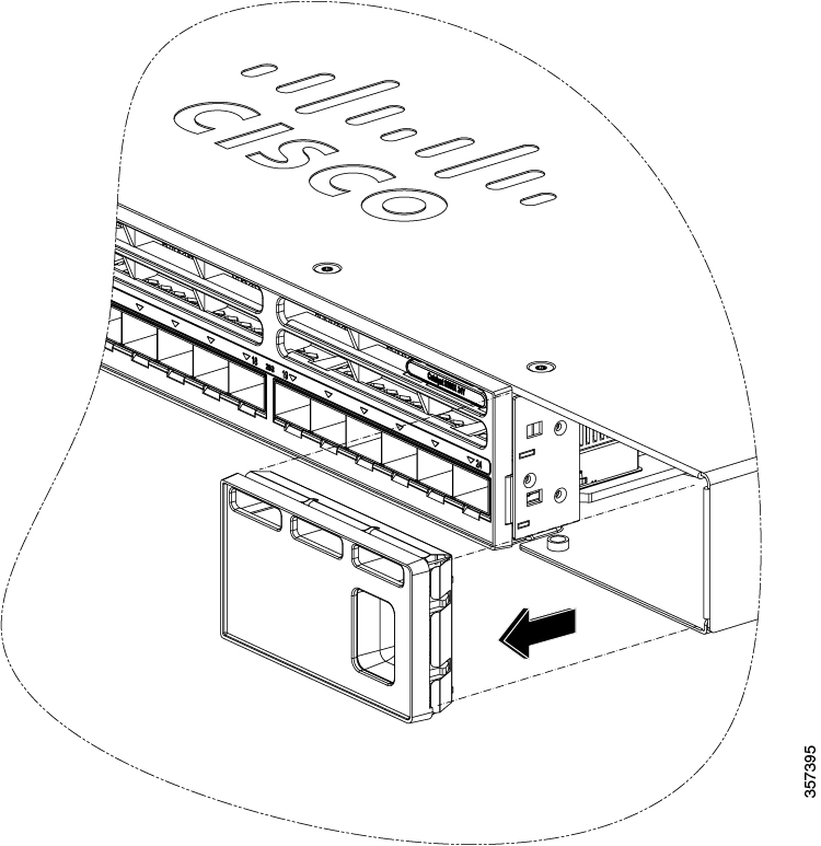 Caution CautionVerify the correct orientation of your module before installing it. Incorrect installation can damage the module. CautionDo not install the network module with connected cables or installed pluggable transceivers. Always remove any cables and transceiver modules before you install the network module. AttentionA module interface might become error-disabled when a network module with connected fiber-optic cables is installed or removed. If an interface is error-disabled, you can re-enable the interface by using the shutdown and no shutdown interface configuration commands. |
Step 4 | While installing Cisco C9350 network modules, position the module face up to install it in the module slot. Slide the module into the slot until the back of the module faceplate is flush with the switch faceplate. Secure the network module in place by the ejector and the latch. 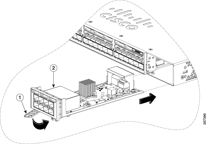
|
Remove a network module
NoteThe switch complies with Electromagnetic Compatibility (EMC), safety, and thermal specifications when a network module is present. If no uplink ports are required, install a blank network module in the slot.
NoteTo avoid authentication failure and non-detection of modules, wait for a minimum of 6-8 seconds between the online insertion and removal (OIR) of network modules.
Step 1 | Attach an ESD-preventive wrist strap to your wrist and to an earth ground surface. CautionDo not remove the network module with connected cables or installed pluggable transceiver modules. Always remove any cables and modules before you remove the network module. CautionA module interface might become error-disabled when a network module with connected fiber-optic cables is installed or removed. If an interface is error-disabled, you can re-enable the interface by using the shutdown and no shutdown interface configuration commands. |
Step 2 | Disconnect the cables from the pluggable transceiver module. |
Step 3 | Remove the pluggable transceiver module from the network module. |
Step 4 | Press the ejector and latch on the network module until it completely disengages from the chassis. |
Step 5 | Carefully slide the network module out of the slot. |
Step 6 | Install a replacement network module or a blank module in the slot. |
Step 7 | Place the module that you removed in an antistatic bag or other protective environment. |
Install and remove Cisco transceiver modules
This section describes how to install and remove Cisco transceiver modules.
Remove Cisco-pluggable transceiver modules
Step 1 | Attach an ESD-preventive wrist strap to your wrist and to an earth ground surface. |
Step 2 | Disconnect the cable from the transceiver module. For reattachment, note which cable connector plug is send (TX) and which is receive (RX). |
Step 3 | Insert a dust plug into the optical ports of the transceiver module to keep the optical interfaces clean. |
Step 4 | If the transceiver module has a bale-clasp latch, pull the bale out and down to eject the module. If you cannot use your finger to open the latch, use a small, flat-blade screwdriver or other long, narrow instrument to open it. |
Step 5 | Grasp the transceiver module, and carefully remove it from the slot. |
Step 6 | Place the transceiver module in an antistatic bag or other protective environment. |
Install and remove power supply modules
Cisco C9350 series smart switches are shipped with preinstalled power supply modules. This section describes how to remove and install a power supply module.
Power supply install guidelines
Adhere to these guidelines when removing or installing a power supply or fan module.
- Do not force the power supply into the slot. This can damage the pins on the switch if they are not aligned with the module.
- A power supply that is only partially connected to the switch can disrupt the system operation.
- Remove power from the power-supply module before removing or installing the module.
-
The power supply is hot-swappable. In some configurations, such as full PoE+ or power sharing mode, removing a power supply causes powered devices to shut down until the power budget matches the input power of a single power supply. To minimize network interruption, hot swap the power supply under these circumstances:
- the switch is in StackPower mode and sufficient power is available, or
- the switch is powered by other switches in a power stack, and no active backup is in progress.
CautionDo not operate the switch with a power-supply module slot empty. For proper chassis cooling, all module slots must be populated, with either a power supply or a blank module.
Take note of the following safety warnings:
WarningStatement 1024—Ground Conductor
This equipment must be grounded. To reduce the risk of electric shock, never defeat the ground conductor or operate the equipment in the absence of a suitably installed ground conductor. Contact the appropriate electrical inspection authority or an electrician if you are uncertain that suitable grounding is available.
WarningStatement 1029—Blank Faceplates and Cover Panels
Blank faceplates and cover panels serve three important functions: they reduce the risk of electric shock and fire, they contain electromagnetic interference (EMI) that might disrupt other equipment, and they direct the flow of cooling air through the chassis. Do not operate the system unless all cards, faceplates, front covers, and rear covers are in place.
Replace and install an AC power supply
Before you begin
WarningStatement 1028—More Than One Power Supply
This unit might have more than one power supply connection. To reduce risk of electric shock, remove all connections to de-energize the unit.
 Note
NoteA power supply must always be installed in slot A; it is the default power supply.
Step 1 | Turn off the power at its source. |
Step 2 | Remove the power cord from the power cord retainer. |
Step 3 | Remove the power cord from the power connector. |
Step 4 | Hold the handle on the left side of the power supply module and slide the power supply out. 
To view the animation in PDF, click this link CautionDo not leave the power-supply slot open for more than 90 seconds while the switch is operating. |
Step 5 | Insert the new power supply module into the power supply slot, and gently push it in. When correctly inserted, the 500 W and 850 W power supplies (excluding the power cord retainer) are flush with the switch rear panel. The 1600 W power supply modules extend 1.5 inches from the switch rear panel. 
To view the animation in PDF, click this link |
Step 6 | (Optional) Use the cable-tie retainer clip on the 1600 W supply. |
Step 7 | Connect the power cord to the power supply and to an AC power outlet. Switch on the power at the power source. Add the power cord to the retainer clip. |
Step 8 | Confirm that the power supply AC OK and PS OK LEDs are green. |
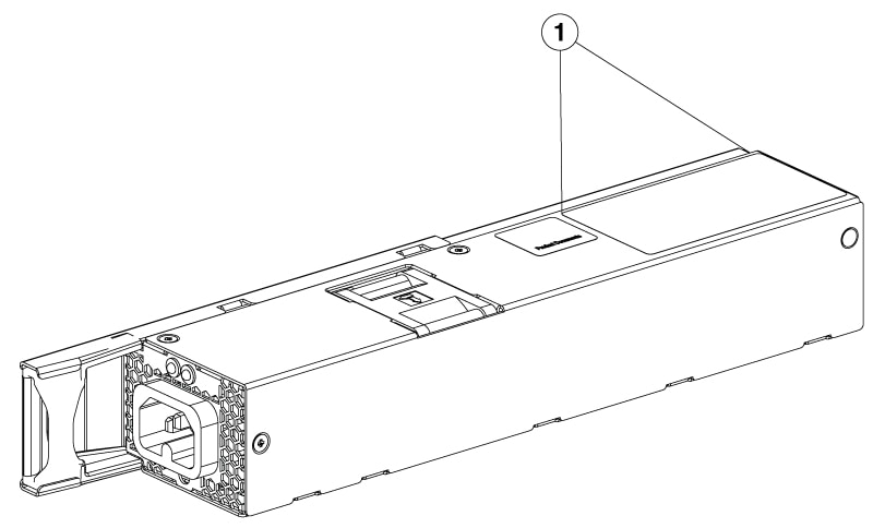
Find the power supply serial number
To contact Cisco Technical Assistance regarding a power supply module, you need to know the serial number. See the following illustrations to find the serial number. You can also use the CLI to find out the serial number.
|
1 |
Serial number location |
Install and remove fan modules
Fan installation guidelines
Adhere to these guidelines when removing or installing a fan module on Cisco C9350 series smart switches.
- Do not force the fan module into the slot. This can damage the pins on the switch if they are not aligned with the module.
- A fan module that is only partially connected to the switch can disrupt the system operation.
- The switch supports hot swapping of the fan module. You can remove and replace the module without interrupting the normal switch operation.
Replacing and installing a fan module
Step 1 | Pinch the fan module release handle, and slide the module out. 
To view the animation in PDF, click this link CautionYou should replace the fan module within 5 minutes to avoid overheating the switch. |
Step 2 | To install the fan module in the fan slot, firmly push it in, applying pressure to the end of the module, not the extraction handles. When correctly inserted, the fan module is flush with the switch rear panel. When the fan is operating, a green LED is on in the top left corner of the fan. 
To view the animation in PDF, click this link |
Find the fan module serial number
To contact Cisco Technical Assistance regarding a fan module, you need to know the fan module serial number. See the following illustration to find the serial number.
|
1 |
Serial number location |
Install and remove an SSD module
Step 1 | Remove the cover on the USB 3.0 SSD slot on the switch and store it for future use. 
To view the animation in PDF, click this link |
Step 2 | Insert the SSD into the module slot, and firmly push it into the slot. Make sure your insert the SSD in such a way that the Cisco label on the drive stays upright. 
To view the animation in PDF, click this link |
Step 3 | Verify that the LED on SSD turns solid green. |
Step 4 | To remove the SSD, hold the SSD on both sides, and slowly pull it out. 
To view the animation in PDF, click this link |
Step 5 | Install a replacement SSD or alternatively, if the slot is to remain empty, install the blank cover. |