
Cisco C9350 Series Smart Switches - Preparing for Installation
Before installing the Cisco C9350 switch
Before you install your Cisco C9350 switch, follow these guidelines.
- Comply with the safety warnings.
- Explore the data stacks options, if you are planning a Switch Data Stack.
- Explore the StackPower stack options, if you are planning a StackPower Stack.
- Verify the contents of the shipping box.
- Ensure that you have the tools and equipment required to install the switch.
- Verify if the switch is powering on.
Safety warnings
This section includes the basic installation caution and warning statements. Read this section before you start the installation procedure. Translations of the warning statements appear in the Regulatory Compliance and Safety Information guide on Cisco.com.
 Warning
Statement 1071—Warning Definition
IMPORTANT SAFETY INSTRUCTIONS
Before you work on any equipment, be aware of the hazards involved with electrical circuitry and be familiar with standard practices for preventing accidents. Read the installation instructions before using, installing, or connecting the system to the power source. Use the statement number at the beginning of each warning statement to locate its translation in the translated safety warnings for this device.
SAVE THESE INSTRUCTIONS

 Note
NoteStatement 407—Japanese Safety Instruction
You are strongly advised to read the safety instruction before using the product.
https://www.cisco.com/web/JP/techdoc/pldoc/pldoc.html
When installing the product, use the provided or designated connection cables/power cables/AC adapters.
〈製品使用における安全上の注意〉
www.cisco.com/web/JP/techdoc/index.html
接続ケーブル、電源コードセット、ACアダプタ、バッテリなどの部品は、必ず添付品または
指定品をご使用ください。添付品・指定品以外をご使用になると故障や動作不良、火災の
原因となります。また、電源コードセットは弊社が指定する製品以外の電気機器には使用
できないためご注意ください。 WarningStatement 445—Connect the Chassis to Earth Ground
To reduce the risk of electric shock, connect the chassis of this equipment to permanent earth ground during normal use.
WarningStatement 1006—Chassis Warning for Rack-Mounting and Servicing
To prevent bodily injury when mounting or servicing this unit in a rack, you must take special precautions to ensure that the system remains stable. The following guidelines are provided to ensure your safety:
- This unit should be mounted at the bottom of the rack if it is the only unit in the rack.
- When mounting this unit in a partially filled rack, load the rack from the bottom to the top with the heaviest component at the bottom of the rack.
- If the rack is provided with stabilizing devices, install the stabilizers before mounting or servicing the unit in the rack.
WarningStatement 1008—Class 1 Laser Product
This product is a Class 1 laser product.
Take note of the following power safety warnings:
WarningStatement 1017—Restricted Area
This unit is intended for installation in restricted access areas. Only skilled, instructed, or qualified personnel can access a restricted access area.
WarningStatement 1028—More Than One Power Supply
This unit might have more than one power supply connection. To reduce risk of electric shock, remove all connections to de-energize the unit.
 Warning
Statement 1055—Class 1/1M Laser
Invisible laser radiation is present. Do not expose to users of telescopic optics. This applies to Class 1/1M laser products.
 Warning
Statement 1073—No User-Serviceable Parts
There are no serviceable parts inside. To avoid risk of electric shock, do not open.
WarningStatement 1074—Comply with Local and National Electrical Codes
To reduce risk of electric shock or fire, installation of the equipment must comply with local and national electrical codes.
WarningStatement 1079—Hot Surface
This icon is a hot surface warning. To avoid personal injury, do not touch without proper protection.
 Note
NoteStatement 1089—Instructed and Skilled Person Definitions
An instructed person is someone who has been instructed and trained by a skilled person and takes the necessary precautions when working with equipment.
A skilled person or qualified personnel is someone who has training or experience in the equipment technology and understands potential hazards when working with equipment.
WarningStatement 1090—Installation by Skilled Person
Only a skilled person should be allowed to install, replace, or service this equipment. See statement 1089 for the definition of a skilled person.
WarningStatement 1091—Installation by an Instructed Person
Only an instructed person or skilled person should be allowed to install, replace, or service this equipment. See statement 1089 for the definition of an instructed or skilled person.
WarningStatement 1099—Before Connecting to System Power Supply
High touch/leakage current—Permanently connected protective earth ground is essential before connecting to the system power supply.
WarningStatement 7003—Shielded Cable Requirements for Intrabuilding Lightning Surge
The intrabuilding port(s) of the equipment or subassembly must use shielded intrabuilding cabling/wiring that is grounded at both ends.The following port(s) are considered intrabuilding ports on this equipment: RJ-45 Copper Ethernet ports.
NoteStatement 7004—Special Accessories Required to Comply with GR-1089 Emission and Immunity Requirements
To comply with the emission and immunity requirements of GR-1089, shielded cables are required for the following ports: RJ-45 Copper Ethernet ports.
WarningStatement 7005—Intrabuilding Lightning Surge and AC Power Fault
The intrabuilding port(s) of the equipment or subassembly is suitable for connection to intrabuilding or unexposed wiring or cabling only. The intrabuilding port(s) of the equipment or subassembly MUST NOT be metallically connected to interfaces that connect to the OSP or its wiring for more than 6 meters (approximately 20 feet). These interfaces are designed for use as intrabuilding interfaces only (Type 2, 4, or 4a ports as described in GR-1089) and require isolation from the exposed OSP cabling. The addition of primary protectors is not sufficient protection in order to connect these interfaces metallically to an OSP wiring system.
The following ports are considered intrabuilding ports on the equipment: RJ-45 Copper Ethernet ports.
NoteStatement 7013—Equipment Grounding Systems—Common Bonding Network (CBN)
This equipment is suitable for installations using the CBN.
NoteStatement 7015—Equipment Bonding and Grounding
When you use thread-forming screws to bond equipment to its mounting metalwork, remove any paint and nonconductive coatings and clean the joining surfaces. Apply an antioxidant compound before joining the surfaces between the equipment and mounting metalwork.
NoteStatement 7016—Battery Return Conductor
Treat the battery return conductor of this equipment as Isolated DC return (DC-I).
NoteStatement 7018—System Recover Time
The equipment is designed to boot up in less than 30 minutes provided the neighboring devices are fully operational.
NoteStatement 8015—Installation Location Network Telecommunications Facilities
This equipment is suitable for installation in network telecommunications facilities.
NoteStatement 8016—Installation Location Where the National Electric Code (NEC) Applies
This equipment is suitable for installation in locations where the NEC applies.
WarningStatement 9001—Product Disposal
Ultimate disposal of this product should be handled according to all national laws and regulations.
NoteInstallation guidelines
When determining where to install the switch, ensure that these guidelines are met.
-
Clearance to the switch front and rear panels meet these conditions.
- Front-panel LEDs can be easily read.
- Access to ports is sufficient for unrestricted cabling.
- AC power cord can reach from the AC power outlet to the connector on the switch rear panel.
- The pluggable transceiver module minimum-bend radius and connector length is met. See the Cisco pluggable transceiver module documentation for more information.
- Cabling is away from sources of electrical noise, such as radios, power lines, and fluorescent lighting fixtures. Make sure that the cabling is safely away from other devices that might damage the cables.
- Airflow around the switch and through the vents is unrestricted.
- For copper connections on Ethernet ports, cable lengths from the switch to connected devices can be up to 328 feet (100 meters).
- Temperature around the unit does not exceed 113°F (45°C). If the switch is installed in a closed or multirack assembly, the temperature around it might be greater than normal room temperature.
- Humidity around the switch does not exceed 95 percent.
- Altitude at the installation site is not greater than 10,000 feet.
- Cooling mechanisms, such as fans and blowers in the switch, can draw dust and other particles causing contaminant buildup inside the chassis, which can result in system malfunction. You must install this equipment in an environment free from dust and foreign conductive or corrosive materials. For more information, see Air Quality and Corrosion.
Site requirements
Planning a proper location for the switch and layout of the equipment rack or wiring closet is essential for successful system operation. These sections describe some of the basic site requirements that you should be aware of as you prepare to install your switch.
- Environmental factors can adversely affect the performance and longevity of your system.
- Install the switch in an enclosed, secure area, ensuring that only qualified personnel have access to the switch and control of the environment.
- Equipment that is placed too closely together or that is inadequately ventilated may cause system over-temperature conditions, leading to premature component failure.
- Poor equipment placement can make chassis panels inaccessible and difficult to maintain.
- The switch requires a dry, clean, well-ventilated, and air-conditioned environment.
- To ensure normal operation, maintain ambient airflow. If the airflow is blocked or restricted, or if the intake air is too warm, an over-temperature condition may occur. The switch environmental monitor may then shut down the system to protect the system components.
Air flow
The switch is designed to be installed in an environment where there is a sufficient volume of air available to cool the switch and its components. If there are any constraints with regard to the free flow of air through the chassis, or if the ambient air temperature is elevated, the switch environmental monitor may then shut down the system to protect the system components.
To maintain proper air circulation through the switch chassis, we recommend that you maintain a minimum space of 6 inches (15 cm) between a wall and the chassis and power supply unit air intakes or a wall and the chassis and power supply unit hot air exhausts. In situations where the switch chassis are installed in adjacent racks, you should allow a minimum space of 12 inches (30.5 cm) between the air intake of one chassis and the hot air exhaust of another chassis. Failure to maintain adequate spacing between chassis may cause the switch chassis that is drawing in the hot exhaust air to overheat and fail.
If you are installing your switch in an enclosed or partially enclosed rack, we strongly recommend that you verify that your site meets these guidelines.
-
Verify that the ambient air temperature within the enclosed or partially enclosed rack is within the chassis operating temperature limits. After installing the chassis in the rack, power up the chassis and allow the chassis temperature to stabilize (approximately 2 hours).
Measure the ambient air temperature at the chassis air intake grill by positioning an external temperature probe 1 inch (2.5 cm) away from the chassis left side, and centered on the chassis both horizontally and vertically.
Measure the ambient air temperature at the power supply unit air intake grill by positioning an external temperature probe 1 inch (2.5 cm) away from the chassis front, centered on the power supply unit section located above the card slots.
- If the ambient intake air temperature is less than 109°F (45°C) at altitudes of 6,000 feet and below, the rack meets the intake air temperature criterion. At altitudes above that threshold and up to 10,000 feet (3000 m), the air intake should not exceed 104°F (40°C).
- If the ambient intake air temperature exceeds this recommendation, the system may experience minor temperature alarms and increase fan speeds in response.
- If the ambient intake air temperature equals or is greater than 131°F (55°C), the system may experience a major temperature alarm with maximum fan speeds in response. If ambient temperature continues to increase, system will respond with protective shut down.
- Plan ahead. A switch that is currently installed in an enclosed or partially enclosed rack might meet ambient air temperature and air flow requirements at present. However, if you add more chassis to the rack or more modules to a chassis in the rack, the additional heat generated might cause the ambient air temperature at the chassis or power supply unit inlets to exceed recommended conditions which may trigger thermal alarms. If installation conditions for inlet temperature and airflow are marginal or not fully met, activate the fan tray’s Network Equipment-Building System (NEBS) mode, which has more aggressive programming to address restricted spacing and elevated ambient temperatures. This should result in reduced thermal alarms along with greater acoustic noise and increased power consumption associated with higher fan speeds.
Air quality
Dust is everywhere and often invisible to the naked eye. It consists of fine particles in the air that originate from various sources, such as soil dust lifted by weather, from volcanic eruptions, or pollution. Dust at an installation site may contain small amounts of textile, paper fibers, or minerals from outdoor soil. It may also contain natural contaminants, such as chlorine from the marine environment and industrial contaminants such as sulfur. Ionized dust and debris are dangerous and get attracted to electronic equipment.
The accumulation of dust and debris on electronic equipment has the following adverse effects:
- It increases the operating temperature of the equipment. According to the Arrhenius effect, an increase in the operating temperature leads to a decrease in reliability and life of the equipment.
- The moisture and corrosive elements that are present in the dust can corrode the electronic or mechanical components and cause premature board failure.
These adverse effects are further accelerated by the presence of fans in the data networking equipment that ingest dust and other particles into the equipment. Higher the volume of air that is generated by the fans for cooling, the higher the quantity of dust and particulates that get deposited and trapped inside the equipment. Remove or minimize the presence of dust and particulates at the installation site by following the guidelines mentioned in ANSI 71-04-2013 regulations.
NoteIn addition to the guidelines mentioned in ANSI 71-04-2013 regulations, follow all applicable guidelines as per site conditions to remove or minimize other contaminants.
Altitude
Operating a system at high altitude (low pressure) reduces the efficiency of forced and convection cooling and may result in electrical problems related to arcing and corona effects. This condition may also cause sealed components with internal pressure, such as electrolytic capacitors, to fail or perform at reduced efficiency.
Corrosion
Corrosion is a chemical reaction that occurs between electronic components and gases which results in metal deterioration. Corrosion attacks edge connectors, pin connectors, IC plug-in sockets, wirewraps, and all other metal components. Depending on the type and concentration level of the corrosive gases, performance degradation of the components occurs either rapidly or over a period of time. It also leads to blocked currents, brittle connection points, and overheated electrical systems. Corrosion by-products form insulating layers on circuits and causes electronic failure, short circuits, pitting, and metal loss.
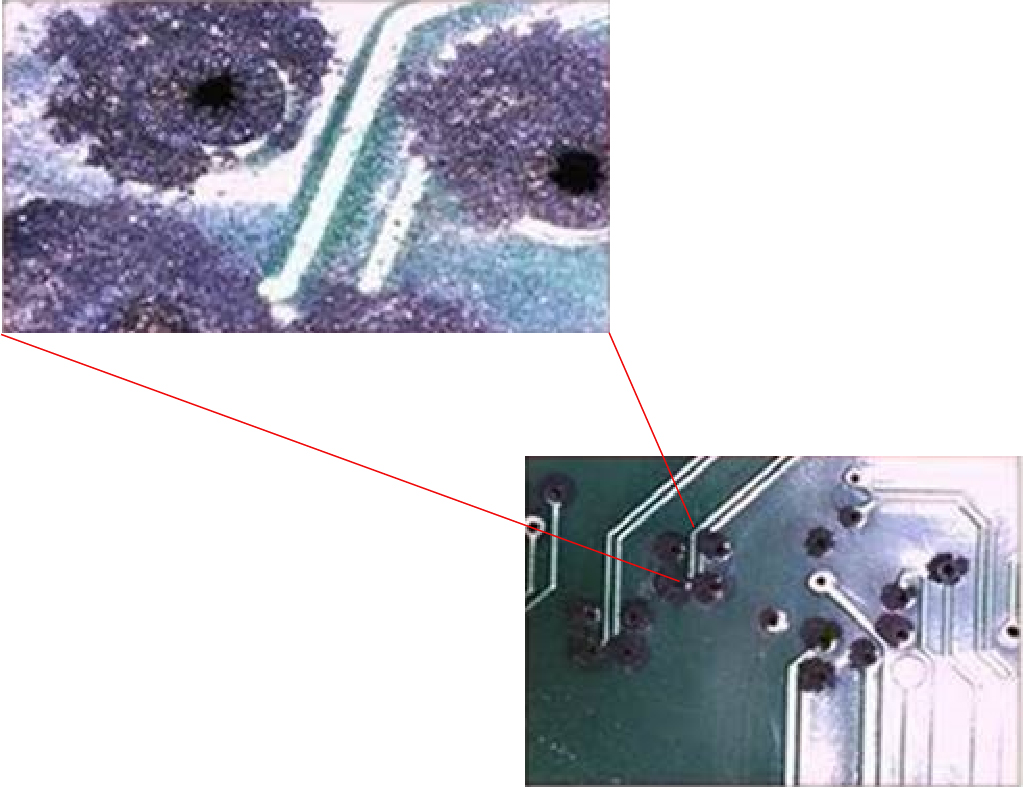
A type of corrosion known as creep corrosion, that primarily affects PCBA (Printed Circuit Board Assembly) occurs when the PCBA is subjected to a harsh, and sulfur-rich (hydrogen sulfide) end-use environment over a prolonged period of time. The corrosion begins on certain exposed metals, such as copper and silver, and then creeps along the remaining metal surface either causing electrical short circuits or creating holes. Creep corrosion also occurs on electronic components such as resistors and PCBs.
To prevent corrosion, remove or minimize the presence of dust and particulates at the installation site by following the guidelines mentioned in ANSI 71-04-2013 regulations.
Dust and particles
Fans cool power supplies and system components by drawing in room-temperature air and exhausting heated air out through various openings in the chassis. However, fans also ingest dust and other particles, causing contaminant buildup in the system and increased internal chassis temperature. A clean operating environment can greatly reduce the negative effects of dust and other particles, which act as insulators and interfere with the mechanical components in the system.
The standards listed below provide guidelines for acceptable working environments and acceptable levels of suspended particulate matter:
- National Electrical Manufacturers Association (NEMA) Type 1
- International Electrotechnical Commission (IEC) IP-20
EMI and radio frequency interference
Electro-Magnetic interference (EMI) and radio frequency interference (RFI) from a system can adversely affect devices such as radio and television (TV) receivers operating near the system. Radio frequencies emanating from a system can also interfere with cordless and low-power telephones. Conversely, RFI from high-power telephones can cause spurious characters to appear on the system monitor. RFI is defined as any EMI with a frequency above 10 kilohertz (kHz). This type of interference can travel from the system to other devices through the power cable and power source, or through the air in the form of transmitted radio waves. The Federal Communications Commission (FCC) publishes specific regulations to limit the amount of harmful interference emitted by computing equipment. Each system meets these FCC regulations. To reduce the possibility of EMI and RFI, follow these guidelines:
- Always operate the system with the chassis covers installed.
- Ensure that all chassis slots are covered by a metal filler bracket and that an unused power supply bay has a metal cover plate installed.
- Ensure that the screws on all peripheral cable connectors are securely fastened to their corresponding connectors on the back of the chassis.
- Always use shielded cables with metal connector shells for attaching peripherals to the system.
When wires are run for any significant distance in an electromagnetic field, interference can occur between the field and the signals on the wires. This fact has two implications for the construction of plant wiring:
- Bad wiring practice can result in radio interference emanating from the plant wiring.
- Strong EMI, especially when it is caused by lightning or radio transmitters, can destroy the signal drivers and receivers in the chassis, and even create an electrical hazard by conducting power surges through lines into equipment.
NoteTo predict and provide a remedy for strong EMI, consult experts in RFI.
If you use twisted-pair cable in your plant wiring, include a good distribution of grounding conductors to reduce EMI. If you exceed the recommended distances, use a high-quality twisted-pair cable with one ground conductor for each data signal when applicable.
If the wires exceed the recommended distances, or if wires pass between buildings, give special consideration to the effect of a lightning strike in your vicinity. The electromagnetic pulse caused by lightning or other high-energy phenomena can easily couple enough energy into unshielded conductors to destroy electronic devices. If you have had problems of this sort in the past, you may want to consult experts in electrical surge suppression and shielding.
 Caution
The intra-building ports (Copper-based Ethernet ports) of the equipment or subassembly is suitable for connection to inside a building or unexposed wiring or cabling only. If the intra-building ports of the equipment or subassembly is metalically connected to interfaces that connect to the Out Side Plant (OSP) or its wiring, the metallic-connection MUST NOT be more than 6 meters (approximately 20 feet). These interfaces are designed for use as intra-building interfaces only (Type 2, 4, or 4a ports as described in GR-1089-CORE) and require isolation from the exposed OSP cabling. The addition of primary protectors is not sufficient protection in order to connect these interfaces metallically to an OSP wiring system.
Humidity
High-humid conditions may cause moisture to enter the system, and cause corrosion of internal components and degradation of properties such as electrical resistance, thermal conductivity, physical strength, and size. Extreme moisture buildup inside the system may result in electrical short circuit, which may cause serious damage to the system.
Each system is rated for storage and operation in 10 to 95 percent relative humidity, non-condensing with a humidity gradation of 10 percent per hour. Buildings in which climate is controlled by air-conditioning in the warmer months and by heat during the colder months usually maintain an acceptable level of humidity for system equipment. However, if a system is located in an unusually humid location, a dehumidifier should be used to maintain the humidity within an acceptable range.
Maintaining safety with electricity
When working on electrical equipment, follow these guidelines.
- Do not work alone if potentially hazardous conditions exist anywhere in your work space.
- Never assume that power is disconnected from a circuit; always check the circuit before working on it.
- When the power is switched off, put a lock-box on the circuit, so that no one can accidentally switch it on.
- Look carefully for possible hazards in your work area, such as damp floors, ungrounded power extension cables, frayed or damaged power cords, and missing safety grounds.
-
If an electrical accident occurs, proceed as follows:
- Use extreme caution; do not become a victim yourself.
- Disconnect power from the system.
- Seek medical attention, if necessary.
- Use the product within its marked electrical ratings and product usage instructions.
- Install the product in compliance with the local and national electrical codes.
-
Contact the Cisco Technical Assistance Center, if any of these conditions occur.
- The power cable or plug is damaged.
- An object has fallen into the product.
- The product has been exposed to water or other liquids.
- The product has been dropped or shows signs of damage.
- The product does not operate correctly when you follow the operating instructions.
- Use the correct external power source. Operate the product only from the type of power source indicated on the electrical ratings label. If you are not sure of the type of power source required, consult a local electrician.
- To help prevent electrical shock, plug all the power cables into properly grounded electrical outlets. These power cables are equipped with three-prong plugs to ensure proper grounding. Do not use adapter plugs or remove the grounding prong from a power cable.
- Observe power strip ratings. Make sure that the total current rating of all products that are plugged into the power strip does not exceed 80 percent of the power strip rating.
- Do not modify power cables or plugs yourself. Consult with a licensed electrician or your power company for site modifications. Always follow your local and national wiring codes.
Power source interruptions
Systems are especially sensitive to variations in voltage supplied by the AC power source. Overvoltage, undervoltage, and transients (or spikes) can erase data from the memory or even cause components to fail. To protect against these types of problems, power wiring ground conductors should always be properly grounded. Also, place the system on a dedicated power circuit (rather than sharing a circuit with other heavy electrical equipment). In general, do not allow the system to share a circuit with any of these machines.
- Copy machines
- Air conditioners
- Vacuum cleaners
- Space heaters
- Power tools
- Teletype machines
- Laser printers
- Facsimile machines
- Any other motorized equipment
Besides these appliances, the greatest threats to a system's power supply are surges or blackouts that are caused by electrical storms. Whenever possible, turn off the system and peripherals, if any, and unplug them from their power sources during thunderstorms. If a blackout occurs—even a temporary one—while the system is turned on, turn off the system immediately and disconnect it from the electrical outlet. Leaving the system on may cause problems when the power is restored; all other appliances left on in the area may create large voltage spikes that may damage the system.
Preventing ESD damage
An electrostatic discharge (ESD) strap, is a tool used to prevent damage to sensitive electronic components from static electricity. It is a wrist strap that connects the wearer to a grounding point, ensuring that any static charge on the body is safely dissipated to the ground, thus preventing damage to electronic components during handling.
ESD damage might occur when modules or other field replaceable units (FRUs) are improperly handled, resulting in intermittent or complete failure of the modules or FRUs. Modules consist of printed circuit boards that are fixed in metal carriers. EMI shielding and connectors are integral components of a carrier. Although the metal carrier helps to protect the board from ESD, always use an ESD-grounding strap when handling modules.
Follow these guidelines to prevent ESD damage.
- Always use an ESD wrist or ankle strap and ensure that it makes good skin contact.
- Connect the equipment end of the strap to an unfinished chassis surface.
- When installing a component, use an available ejector lever to properly seat the bus connectors in the backplane or midplane. These devices prevent accidental removal, provide proper grounding for the system, and help to ensure that bus connectors are properly seated.
- When removing a component, use an available ejector lever to release the bus connectors from the backplane or midplane.
- Handle carriers by available handles or edges only; avoid touching the printed circuit boards or connectors.
- Place a removed component board-side-up on an antistatic surface or in a static-shielding container. If you plan to return the component to the factory, immediately place it in a static-shielding container.
- Avoid contact between the printed circuit boards and clothing. The wrist strap only protects components from ESD voltages on the body; ESD voltages on clothing can still cause damage.
- Never attempt to remove the printed circuit board from the metal carrier.
Shock and vibration
The Cisco C9350 series smart switches comply with the Earthquake, Office, and Transportation Vibration, and Equipment Handling Criteria of GR-63-CORE.
System grounding
WarningStatement 1046—Installing or Replacing the Unit
To reduce risk of electric shock, when installing or replacing the unit, the ground connection must always be made first and disconnected last.
If your unit has modules, secure them with the provided screws.
You must install a system ground as part of the chassis installation process. Chassis installations that rely only on the AC third-prong ground are insufficient to adequately ground the systems. If installing in NEBS-compliant mode, you must install an NEBS-compliant system ground as part of the chassis installation process.
Proper grounding practices ensure that the buildings and the installed equipment within them have low-impedance connections and low-voltage differentials between chassis. When you install a system ground, you reduce or prevent shock hazards, chances of equipment damage due to transients, and the potential for data corruption.
Without proper and complete system grounding, you run the risk of increased component damage due to ESD. Additionally, you have a greatly increased chance of data corruption, system lockup, and frequent system reboot situations by not using a system ground.
CautionThis table lists some general grounding practice guidelines.
|
Environment |
Electromagnetic noise severity level |
Grounding recommendations |
|---|---|---|
|
Commercial building is subjected to direct lightning strikes. For example, some places in the United States, such as Florida, are prone to more lightning strikes than other areas. |
High |
All lightning protection devices must be installed in strict accordance with manufacturer recommendations. Conductors carrying lightning current should be spaced away from power and data lines in accordance with applicable recommendations and building codes. Best grounding practices must be closely followed. |
|
Commercial building is located in an area where lightning storms occur frequently, but is not prone to direct lightning strikes. |
High |
Best grounding practices must be closely followed. |
|
Commercial building contains a mix of information technology equipment and industrial equipment, such as welding. |
Medium to High |
Best grounding practices must be closely followed. |
|
Existing commercial building is not subject to natural environmental noise or man-made industrial noise. This building contains a standard office environment. This installation has a history of malfunction due to electromagnetic noise. |
Medium |
Best grounding practices must be closely followed. Determine source and cause of noise if possible, and mitigate as closely as possible at the noise source or reduce coupling from the noise source to the victim equipment. |
|
New commercial building is not subject to natural environmental noise or man-made industrial noise. This building contains a standard office environment. |
Low |
Best grounding practices should be followed as closely as possible. Electromagnetic noise problems are not anticipated, but installing a best-practice grounding system in a new building is often the least expensive route, and the best way to plan for the future. |
|
Existing commercial building is not subject to natural environmental noise or man-made industrial noise. This building contains a standard office environment. |
Low |
Best grounding practices should be followed as much as possible. Electromagnetic noise problems are not anticipated, but installing a best-practice grounding system is always recommended. |
Note Note NoteTemperature
Temperature extremes may cause a system to operate at reduced efficiency and cause a variety of problems, including premature aging and failure of chips, and failure of mechanical devices. Extreme temperature fluctuations may also cause chips to become loose in their sockets. Observe these guidelines:
- Ensure that the chassis has adequate ventilation.
- Do not place the chassis within a closed-in wall unit or on top of cloth, which can act as thermal insulation.
- Do not place the chassis where it will receive direct sunlight, particularly in the afternoon.
- Do not place the chassis next to a heat source of any kind, including heating vents.
- Adequate ventilation is particularly important at high altitudes. Make sure that all the slots and openings on the system remain unobstructed, especially the fan vent on the chassis.
- Clean the installation site at regular intervals to avoid buildup of dust and debris, which may cause a system to overheat.
- If system is exposed to abnormally low temperatures, allow a two hour warm up period, in ambient temperature no lower than 32°F (0 °C) before turning on.
Failure to observe these guidelines may damage the internal components of the chassis.
Shipping box contents
The shipping box contains the model of the switch you ordered and other components needed for installation. Some components are optional, depending on your order.
NoteVerify that you have received these items. If any item is missing or damaged, contact your Cisco representative or reseller for instructions.
|
Item |
Quantity |
|---|---|
|
Cisco C9350 Series Smart Switch with optional network module1 |
1 |
|
AC power cord |
1 |
|
Documentation pointer card Product documentation and compliance document |
1 |
|
Rubber mounting feet |
4 |
|
Ground lug screw and ring terminal |
1 |
|
Number 12 pan-head screws |
4 |
|
Number 10 pan-head screws |
4 |
|
Number 8 Phillips flat-head screws |
8 |
|
Cable guide |
1 |
|
M4.0 x 20mm Phillips pan-head screw |
1 |
|
(Optional) RJ-45 console cable1 |
- |
|
(Optional) USB console cable1 |
- |
|
(Optional) StackWise-1.6T cable (0.5-meter, 1-meter, or 3-meter)1 |
- |
|
(Optional) StackPower cable (0.35-meter or 1-meter)1 |
- |
Note- The item is orderable.
Tools and equipment
You need a Number-2 Phillips screwdriver for installing your Cisco C9350 switch.
Verifying the switch operation
Before you install the switch in a rack, or on a table or shelf, power on the switch and verify that it passes the Power-On Self Test (POST). POST is an automatic diagnostic process that runs immediately when a switch is powered on. Its primary purpose is to verify the integrity and basic functionality of the switch hardware components before the operating system loads.
To power on the switch, plug one end of the AC power cord into the switch AC power connector, and plug the other end into an AC power outlet.
As the switch powers on, it begins the POST, and a series of tests run automatically to ensure that the switch functions properly. LEDs can blink during the test; the SYST LED blinks green, and the other LEDs remain solid green.
When the switch completes POST successfully, the SYST LED remains green. The other LEDs turn off and then reflect the switch operating status. If a switch fails POST, the SYST LED turns amber.
POST failures are usually fatal. Call Cisco technical support representative if your switch fails POST.
After a successful POST, unplug the power cord from the switch and install the switch in a rack, on a table, or on a shelf.
When to plan for a data and power stack
Before you install your Cisco C9350 switch, you must decide on your data stack and power stack requirements.
StackWise stack
A Cisco data stack is a network solution that combines multiple stackable switches to function as a single logical device. Data stacks allows network administrators to expand the network capacity and manage multiple switches as a single unit. Cisco StackWise is a data stack that allows two physical switches to operate as a single logical switch. It simplifies management, provides high availability, and enhances scalability in enterprise networks, data centers, and campus environments.
Up to eight Cisco C9350 series switches can be connected together through the StackWise ports, using the StackWise cables to form a data stack.
StackPower stack
A StackPower Stack is a power management solution for Cisco switches that combines the available power supplies in multiple connected switches into a single shared power pool. This technology allows for more efficient power distribution and management across a stack of switches. With Cisco StackPower, a common pool of power is made available to all switches in the stack, and the additional power is automatically redirected to the appropriate switch based on the available power budget in the common power pool.
You can stack up to four switches together through the StackPower ports, using the StackPower cables to form a power stack. So a full eight-switch stack, forms two separate power pools, each sharing power among their four members.
For more information about data stacks and power stacks, see the Stacking document.
Planning a switch data stack
Cisco C9350 switches can share bandwidth by using data stacking. This table lists the supported stacking options.
|
Switch model |
Stacking option |
Supported bandwidth |
Number of members |
Supported stack members |
|---|---|---|---|---|
|
Cisco C9350 series smart switches |
StackWise-1.6T |
1.6 Tbps |
Up to a maximum of eight |
Stacks with other Cisco C9350 models at StackWise-1.6T speeds with same license level |
Data stacking guidelines
Refer to these stacking guidelines before connecting the switches in a stack.
- Size of the switch and any optional power supply module: The 1600 W power supply module is longer than the other modules. Stacking switches with the same power supply modules together makes it easier to cable the switches.
- Length of cable: Depending on the configurations that you have, you might need different sized cables. If you do not specify the length of the StackWise cable, the 0.5 meter cable is supplied. If you need the 1 meter cable or the 3 meter cable, you can order it from your Cisco supplier. For cable part numbers, see StackWise accessories section. The Data stack cabling configurations provides examples of recommended configurations.
Data stack cabling configurations
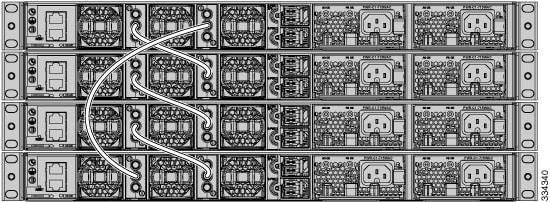
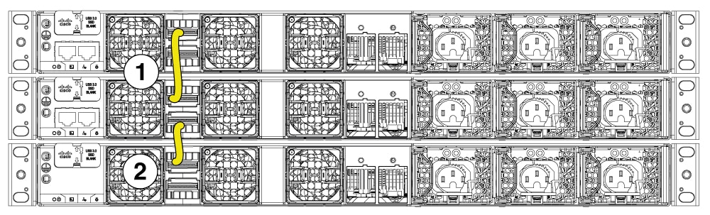
This is an example of a recommended data stacking configuration that uses the supplied 0.5-meter StackWise cable. In this example, the switches are stacked in a vertical rack or on a table. This example shows a full-ring configuration that provides redundant connections.
This example shows a configuration when the switches are mounted side-by-side. Use the 1-meter and the 3-meter StackWise cables to connect the switches. This configuration provides redundant connections.

Data stack bandwidth and partitioning
This section provides examples of data stack bandwidth and possible data stack partitioning.
This figure shows a data stack of switches that provides full bandwidth and redundant StackWise cable connections.
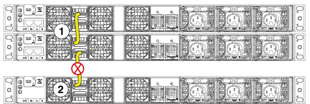
This figure shows a switch stack with incomplete StackWise cabling connections. This stack provides only half-bandwidth and does not have redundant connections.
This sections describes data stacks of switches with failover conditions.
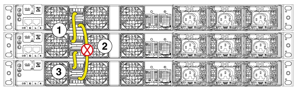
In this figure, the StackWise cable is faulty in link 2. Therefore, this stack provides only half bandwidth and does not have redundant connections.
In this figure, link 2 is faulty. Therefore, this stack partitions into two stacks. Top two switches form one stack and the bottom switch become the single active switch. If the bottom switch was a member of the stack previously, (not active or standby switch), it will reload to become active.
Power-on sequence for switch stacks
Consider these guidelines before you power on the switches in a stack.
- The sequence in which the switches are first powered on might affect the switch that becomes the stack master.
-
You can elect an active switch either by
- configuring the highest priority for the switch among all other switches in the stack.
- or, by powering on that switch first. This switch remains the active switch until a reelection is required. Power on the other switches in the stack, two minutes after powering on the active switch.
- If you have no preference as to which switch becomes the active switch, power on all the switches in the stack within 180 seconds. Only stack members that are powered on within the same 180-second timeframe from the initial power-on of the stack can participate in the active switch election and have a chance to become the active switch. Stack members powered on after this window will join the stack as regular members and will not participate in the initial election.
- Among the switches with same priority, the switch with the lowest MAC address becomes the active switch.
If changes are made to the stack without powering down the switches, the following results can occur:
- If two operating partial ring stacks are connected together using a stack cable, a stack merge will take place, and one of the partial stacks will reload.
- If some switches in the stack are completely separated from the stack, a stack split can occur.
-
A stack split can occur on a full ring stack if
- more than one running switch is removed without powering down, or
- more than one stack cable is removed without powering down.
-
A stack split can occur in a partial ring stack if
- a switch is removed without powering down, or
- a stack cable is removed without powering down.
- In a split stack, depending on where the active and standby switches are located, either two stacks might be formed (with the standby taking over as the new active switch in the newly formed stack) or all the members in the newly formed stack might reload.
NotePlanning a StackPower stack
This section describes the StackPower stacking guidelines, cabling configurations, and partitioning examples.
StackPower stacking guidelines
You can configure a StackPower stack for either power sharing or redundancy. In power-sharing mode, the power of all the power supplies in the stack is aggregated and distributed among the stack members.
In redundant mode, when the total power budget of the stack is calculated, the wattage of the largest power supply is not included. That power is held in reserve and used to maintain power to the switches and attached devices when one power supply fails. Following the failure of a power supply, the StackPower mode becomes power-sharing mode.
NoteFor general concepts and management procedures for switch power stacks, see the Software Configuration Guide on Cisco.com.
Before connecting the switches in a power stack, read the following guidelines:
- Cisco C9350 switches support Cisco StackPower providing up to 1000 W of power in nominal conditions and 2400 W of power in failure conditions across a power stack.
- Up to four switches can be configured in a StackPower stack using the StackPower connector at the rear of the switch.
- A switch power stack can include a maximum of four switches in a ring topology. If a switch stack has more than four switches, we will have more than one StackPower groups.
- Size of the switch and any optional power supply module: Stacking switches with the same power supply modules together makes it easier to cable the switches. The 1600W power supply module is 3.14 inches (8 cm) longer than the other modules.
- Length of cable: Depending on the configurations that you have, you might need different sized cables. If you do not specify the length of the StackPower cable, the 0.35 meter cable is supplied. If you need the 1 meter cable, you can order it from your Cisco supplier. The Data stack cabling configurations provides examples of recommended configurations.
StackPower cabling configurations
This section describes the recommended cabling configurations for a StackPower stack.
The two types of StackPower cables are
| Part Number | Cable Type | Length |
|---|---|---|
|
CAB-SPWR-35CM= |
StackPower Cable |
0.35 meter |
|
CAB-SPWR-100CM= |
StackPower Cable |
1 meter |
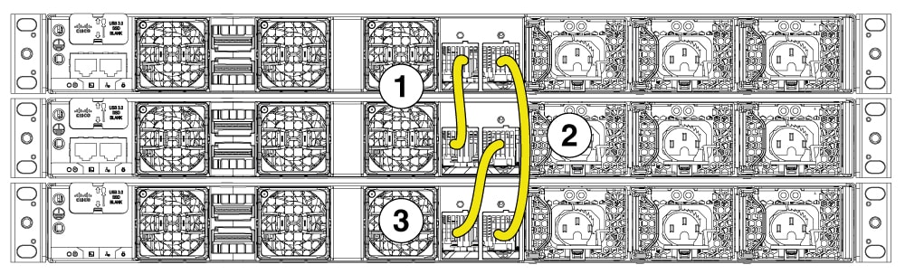
Stackpower partitioning examples
The examples in this section displays StackPower stacks of switches with failover conditions.
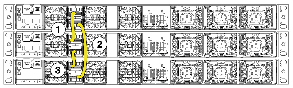
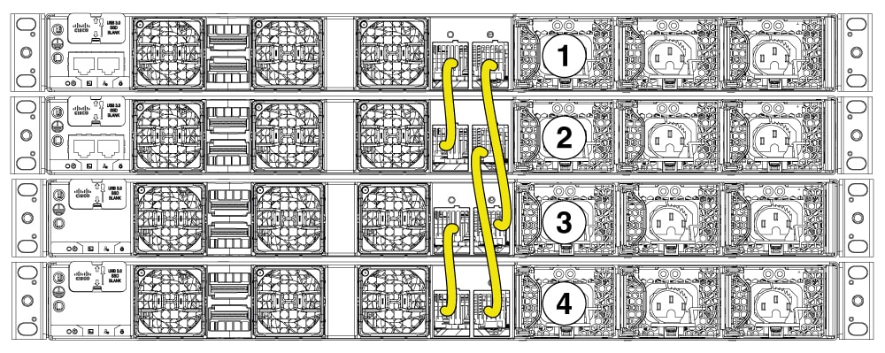
In this illustration, the StackPower cable 2 is faulty. This is considered a broken ring and is a fault condition. Power is still shared across the stack, but this condition will place a limitation on power budgeting and the number of high priority ports it can protect in the case of further failures, such as, failure of power supply, AC mains, StackPower port, and so on. StackPower is not intended for secondary failures and hence restoration of the failed component or power should be done immediately.
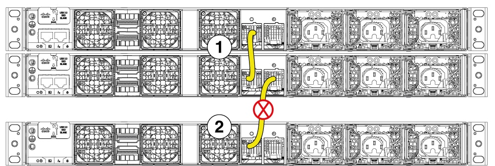
In this illustration, StackPower port B on the center switch has failed and the stack partitions into two stacks. The top two switches share power, and the bottom switch is now a separate stack. After the initial failure of cable 2, any further failure of a port is considered a double fault, which StackPower cannot handle. A double fault could result in unintended high priority ports being shut. If you are unable to physically restore a bad cable, adjust the port priorities and restore any offline supplies, as available.
Powering on the switches in a stack
Power on all switches in a stack only after connecting the StackWise and StackPower cables.
Unexpected or unsupported stack-split failures may occur, when
- switches are powered on before connecting the StackWise cables, or
- connecting already powered-on switches in a stack to an existing online stack, after modifying the StackWise cabling.