
Contents
- Administering the System
- Finding Feature Information
- Information About Administering the Switch
- System Time and Date Management
- System Clock
- Network Time Protocol
- NTP Stratum
- NTP Associations
- NTP Security
- NTP Implementation
- NTP Version 4
- System Name and Prompt
- Stack System Name and Prompt
- Default System Name and Prompt Configuration
- DNS
- Default DNS Settings
- Login Banners
- Default Banner Configuration
- MAC Address Table
- MAC Address Table Creation
- MAC Addresses and VLANs
- MAC Addresses and Switch Stacks
- Default MAC Address Table Settings
- ARP Table Management
- How to Administer the Switch
- Configuring the Time and Date Manually
- Setting the System Clock
- Configuring the Time Zone
- Configuring Summer Time (Daylight Saving Time)
- Configuring a System Name
- Setting Up DNS
- Configuring a Message-of-the-Day Login Banner
- Configuring a Login Banner
- Managing the MAC Address Table
- Changing the Address Aging Time
- Configuring MAC Address Change Notification Traps
- Configuring MAC Address Move Notification Traps
- Configuring MAC Threshold Notification Traps
- Adding and Removing Static Address Entries
- Configuring Unicast MAC Address Filtering
- Monitoring and Maintaining Administration of the Switch
- Configuration Examples for Switch Administration
- Setting the System Clock: Example
- Configuring Summer Time: Examples
- Configuring a MOTD Banner: Example
- Configuring a Login Banner: Example
- Configuring MAC Address Change Notification Traps: Example
- Configuring MAC Threshold Notification Traps: Example
- Adding the Static Address to the MAC Address Table: Example
- Configuring Unicast MAC Address Filtering: Example
- Additional References for Switch Administration
- Feature History and Information for Switch Administration
Administering the System
This module contains the following topics:
- Finding Feature Information
- Information About Administering the Switch
- How to Administer the Switch
- Monitoring and Maintaining Administration of the Switch
- Configuration Examples for Switch Administration
- Additional References for Switch Administration
- Feature History and Information for Switch Administration
Finding Feature Information
Your software release may not support all the features documented in this module. For the latest feature information and caveats, see the release notes for your platform and software release.
Use Cisco Feature Navigator to find information about platform support and Cisco software image support. To access Cisco Feature Navigator, go to http://www.cisco.com/go/cfn. An account on Cisco.com is not required.
Related References
Information About Administering the Switch
- System Time and Date Management
- System Clock
- Network Time Protocol
- System Name and Prompt
- DNS
- Login Banners
- MAC Address Table
- ARP Table Management
System Clock
The basis of the time service is the system clock. This clock runs from the moment the system starts up and keeps track of the date and time.
The system clock can then be set from these sources:
The system clock can provide time to these services:
The system clock keeps track of time internally based on Coordinated Universal Time (UTC), also known as Greenwich Mean Time (GMT). You can configure information about the local time zone and summer time (daylight saving time) so that the time appears correctly for the local time zone.
The system clock keeps track of whether the time is authoritative or not (that is, whether it has been set by a time source considered to be authoritative). If it is not authoritative, the time is available only for display purposes and is not redistributed.
Network Time Protocol
The NTP is designed to time-synchronize a network of devices. NTP runs over User Datagram Protocol (UDP), which runs over IP. NTP is documented in RFC 1305.
An NTP network usually gets its time from an authoritative time source, such as a radio clock or an atomic clock attached to a time server. NTP then distributes this time across the network. NTP is extremely efficient; no more than one packet per minute is necessary to synchronize two devices to within a millisecond of one another.
NTP Stratum
NTP uses the concept of a stratum to describe how many NTP hops away a device is from an authoritative time source. A stratum 1 time server has a radio or atomic clock directly attached, a stratum 2 time server receives its time through NTP from a stratum 1 time server, and so on. A device running NTP automatically chooses as its time source the device with the lowest stratum number with which it communicates through NTP. This strategy effectively builds a self-organizing tree of NTP speakers.
NTP avoids synchronizing to a device whose time might not be accurate by never synchronizing to a device that is not synchronized. NTP also compares the time reported by several devices and does not synchronize to a device whose time is significantly different than the others, even if its stratum is lower.
NTP Associations
The communications between devices running NTP (known as associations) are usually statically configured; each device is given the IP address of all devices with which it should form associations. Accurate timekeeping is possible by exchanging NTP messages between each pair of devices with an association. However, in a LAN environment, NTP can be configured to use IP broadcast messages instead. This alternative reduces configuration complexity because each device can simply be configured to send or receive broadcast messages. However, in that case, information flow is one-way only.
NTP Implementation
Implementation of NTP does not support stratum 1 service; it is not possible to connect to a radio or atomic clock. We recommend that the time service for your network be derived from the public NTP servers available on the IP Internet.
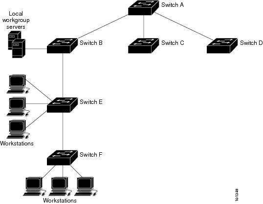
Figure 1. Typical NTP Network Configuration. The following figure shows a typical network example using NTP. Switch A is the NTP master, with the Switch B, C, and D configured in NTP server mode, in server association with Switch A. Switch E is configured as an NTP peer to the upstream and downstream switches, Switch B and Switch F, respectively.
If the network is isolated from the Internet, NTP allows a device to act as if it is synchronized through NTP, when in fact it has learned the time by using other means. Other devices then synchronize to that device through NTP.
When multiple sources of time are available, NTP is always considered to be more authoritative. NTP time overrides the time set by any other method.
Several manufacturers include NTP software for their host systems, and a publicly available version for systems running UNIX and its various derivatives is also available. This software allows host systems to be time-synchronized as well.
NTP Version 4
NTP version 4 is implemented on the switch. NTPv4 is an extension of NTP version 3. NTPv4 supports both IPv4 and IPv6 and is backward-compatible with NTPv3.
NTPv4 provides these capabilities:
- Support for IPv6.
- Improved security compared to NTPv3. The NTPv4 protocol provides a security framework based on public key cryptography and standard X509 certificates.
- Automatic calculation of the time-distribution hierarchy for a network. Using specific multicast groups, NTPv4 automatically configures the hierarchy of the servers to achieve the best time accuracy for the lowest bandwidth cost. This feature leverages site-local IPv6 multicast addresses.
System Name and Prompt
You configure the system name on the switch to identify it. By default, the system name and prompt are Switch.
If you have not configured a system prompt, the first 20 characters of the system name are used as the system prompt. A greater-than symbol [>] is appended. The prompt is updated whenever the system name changes.
Stack System Name and Prompt
If you are accessing a stack member through the active switch, you must use the session stack-member-number privileged EXEC command. The stack member number range is from 1 through 9. When you use this command, the stack member number is appended to the system prompt. For example, Switch-2# is the prompt in privileged EXEC mode for stack member 2, and the system prompt for the switch stack is Switch.
DNS
The DNS protocol controls the Domain Name System (DNS), a distributed database with which you can map hostnames to IP addresses. When you configure DNS on your switch, you can substitute the hostname for the IP address with all IP commands, such as ping, telnet, connect, and related Telnet support operations.
IP defines a hierarchical naming scheme that allows a device to be identified by its location or domain. Domain names are pieced together with periods (.) as the delimiting characters. For example, Cisco Systems is a commercial organization that IP identifies by a com domain name, so its domain name is cisco.com. A specific device in this domain, for example, the File Transfer Protocol (FTP) system is identified as ftp.cisco.com.
To keep track of domain names, IP has defined the concept of a domain name server, which holds a cache (or database) of names mapped to IP addresses. To map domain names to IP addresses, you must first identify the hostnames, specify the name server that is present on your network, and enable the DNS.
Login Banners
You can configure a message-of-the-day (MOTD) and a login banner. The MOTD banner is displayed on all connected terminals at login and is useful for sending messages that affect all network users (such as impending system shutdowns).
The login banner is also displayed on all connected terminals. It appears after the MOTD banner and before the login prompts.
The MOTD and login banners are not configured.
MAC Address Table
The MAC address table contains address information that the switch uses to forward traffic between ports. All MAC addresses in the address table are associated with one or more ports. The address table includes these types of addresses:
- Dynamic address—A source MAC address that the switch learns and then ages when it is not in use.
- Static address—A manually entered unicast address that does not age and that is not lost when the switch resets.
The address table lists the destination MAC address, the associated VLAN ID, and port number associated with the address and the type (static or dynamic).
- MAC Address Table Creation
- MAC Addresses and VLANs
- MAC Addresses and Switch Stacks
- Default MAC Address Table Settings
MAC Address Table Creation
With multiple MAC addresses supported on all ports, you can connect any port on the switch to other network devices. The switch provides dynamic addressing by learning the source address of packets it receives on each port and adding the address and its associated port number to the address table. As devices are added or removed from the network, the switch updates the address table, adding new dynamic addresses and aging out those that are not in use.
The aging interval is globally configured. However, the switch maintains an address table for each VLAN, and STP can accelerate the aging interval on a per-VLAN basis.
The switch sends packets between any combination of ports, based on the destination address of the received packet. Using the MAC address table, the switch forwards the packet only to the port associated with the destination address. If the destination address is on the port that sent the packet, the packet is filtered and not forwarded. The switch always uses the store-and-forward method: complete packets are stored and checked for errors before transmission.
MAC Addresses and VLANs
All addresses are associated with a VLAN. An address can exist in more than one VLAN and have different destinations in each. Unicast addresses, for example, could be forwarded to port 1 in VLAN 1 and ports 9, 10, and 1 in VLAN 5.
Each VLAN maintains its own logical address table. A known address in one VLAN is unknown in another until it is learned or statically associated with a port in the other VLAN.
When private VLANs are configured, address learning depends on the type of MAC address:
- Dynamic MAC addresses learned in one VLAN of a private VLAN are replicated in the associated VLANs. For example, a MAC address learned in a private-VLAN secondary VLAN is replicated in the primary VLAN.
- Static MAC addresses configured in a primary or secondary VLAN are not replicated in the associated VLANs. When you configure a static MAC address in a private VLAN primary or secondary VLAN, you should also configure the same static MAC address in all associated VLANs.
MAC Addresses and Switch Stacks
The MAC address tables on all stack members are synchronized. At any given time, each stack member has the same copy of the address tables for each VLAN. When an address ages out, the address is removed from the address tables on all stack members. When a switch joins a switch stack, that switch receives the addresses for each VLAN learned on the other stack members. When a stack member leaves the switch stack, the remaining stack members age out or remove all addresses learned by the former stack member.
ARP Table Management
To communicate with a device (over Ethernet, for example), the software first must learn the 48-bit MAC address or the local data link address of that device. The process of learning the local data link address from an IP address is called address resolution.
The Address Resolution Protocol (ARP) associates a host IP address with the corresponding media or MAC addresses and the VLAN ID. Using an IP address, ARP finds the associated MAC address. When a MAC address is found, the IP-MAC address association is stored in an ARP cache for rapid retrieval. Then the IP datagram is encapsulated in a link-layer frame and sent over the network. Encapsulation of IP datagrams and ARP requests and replies on IEEE 802 networks other than Ethernet is specified by the Subnetwork Access Protocol (SNAP). By default, standard Ethernet-style ARP encapsulation (represented by the arpa keyword) is enabled on the IP interface.
ARP entries added manually to the table do not age and must be manually removed.
How to Administer the Switch
- Configuring the Time and Date Manually
- Configuring a System Name
- Setting Up DNS
- Configuring a Message-of-the-Day Login Banner
- Configuring a Login Banner
- Managing the MAC Address Table
Configuring the Time and Date Manually
If no other source of time is available, you can manually configure the time and date after the system is restarted. The time remains accurate until the next system restart. We recommend that you use manual configuration only as a last resort. If you have an outside source to which the switch can synchronize, you do not need to manually set the system clock.
Note
You must reconfigure this setting if you have manually configured the system clock before the active switch fails and a different stack member assumes the role of active switch.
Setting the System Clock
SUMMARY STEPSIf you have an outside source on the network that provides time services, such as an NTP server, you do not need to manually set the system clock.
Beginning in privileged EXEC mode, follow these steps to set the system clock:
DETAILED STEPS
Command or Action Purpose Step 1 Use one of the following:
Example:Switch# clock set 13:32:00 23 July 2001Configuring the Time Zone
SUMMARY STEPS
DETAILED STEPS
Configuring Summer Time (Daylight Saving Time)
SUMMARY STEPSTo configure summer time (daylight saving time) in areas where it starts and ends on a particular day of the week each year, perform this task:
2. clock summer-time zone date date month year hh:mm date month year hh:mm [offset]]
3. clock summer-time zone recurring [ week day month hh:mm week day month hh:mm [ offset]]
DETAILED STEPS
Configuring a System Name
SUMMARY STEPS
DETAILED STEPS
Setting Up DNS
SUMMARY STEPSIf you use the switch IP address as its hostname, the IP address is used and no DNS query occurs. If you configure a hostname that contains no periods (.), a period followed by the default domain name is appended to the hostname before the DNS query is made to map the name to an IP address. The default domain name is the value set by the ip domain-name global configuration command. If there is a period (.) in the hostname, the Cisco IOS software looks up the IP address without appending any default domain name to the hostname.
DETAILED STEPS
Configuring a Message-of-the-Day Login Banner
SUMMARY STEPSYou can create a single or multiline message banner that appears on the screen when someone logs in to the switch
DETAILED STEPS
Configuring a Login Banner
SUMMARY STEPSYou can configure a login banner to be displayed on all connected terminals. This banner appears after the MOTD banner and before the login prompt.
DETAILED STEPS
Managing the MAC Address Table
- Changing the Address Aging Time
- Configuring MAC Address Change Notification Traps
- Configuring MAC Address Move Notification Traps
- Configuring MAC Threshold Notification Traps
- Adding and Removing Static Address Entries
- Configuring Unicast MAC Address Filtering
Changing the Address Aging Time
SUMMARY STEPS
DETAILED STEPS
Configuring MAC Address Change Notification Traps
SUMMARY STEPS
2. snmp-server host host-addr { traps | informs} { version { 1 | 2c | 3}} community-string notification-type
3. snmp-server enable traps mac-notification change
4. mac address-table notification change
5. mac address-table notification change [ interval value] [ history-size value]
DETAILED STEPS
Configuring MAC Address Move Notification Traps
SUMMARY STEPSWhen you configure MAC-move notification, an SNMP notification is generated and sent to the network management system whenever a MAC address moves from one port to another within the same VLAN.
Beginning in privileged EXEC mode, follow these steps to configure the switch to send MAC address-move notification traps to an NMS host:
2. snmp-server host host-addr { traps | informs} { version { 1 | 2c | 3}} community-string notification-type
3. snmp-server enable traps mac-notification move
DETAILED STEPS
Configuring MAC Threshold Notification Traps
SUMMARY STEPSWhen you configure MAC threshold notification, an SNMP notification is generated and sent to the network management system when a MAC address table threshold limit is reached or exceeded.
2. snmp-server host host-addr { traps | informs} { version { 1 | 2c | 3}} community-string notification-type
3. snmp-server enable traps mac-notification threshold
4. mac address-table notification threshold
5. mac address-table notification threshold [ limit percentage] | [ interval time]
DETAILED STEPS
Adding and Removing Static Address Entries
SUMMARY STEPS
1. configure terminal
2. mac address-table static mac-addr vlan vlan-id interface interface-id
3. end
DETAILED STEPS
Configuring Unicast MAC Address Filtering
SUMMARY STEPS
DETAILED STEPS
Monitoring and Maintaining Administration of the Switch
Command Purpose clear mac address-table dynamic
Removes all dynamic entries.
clear mac address-table dynamic address mac-address
Removes a specific MAC address.
clear mac address-table dynamic interface interface-id
Removes all addresses on the specified physical port or port channel.
clear mac address-table dynamic vlan vlan-id
Removes all addresses on a specified VLAN.
show clock [detail]
Displays the time and date configuration.
show ip igmp snooping groups
Displays the Layer 2 multicast entries for all VLANs or the specified VLAN.
show mac address-table address mac-address
Displays MAC address table information for the specified MAC address.
show mac address-table aging-time
Displays the aging time in all VLANs or the specified VLAN.
show mac address-table count
Displays the number of addresses present in all VLANs or the specified VLAN.
show mac address-table dynamic
Displays only dynamic MAC address table entries.
show mac address-table interface interface-name
Displays the MAC address table information for the specified interface.
show mac address-table move update
Displays the MAC address table move update information.
show mac address-table multicast
Displays a list of multicast MAC addresses.
show mac address-table notification {change | mac-move | threshold}
Displays the MAC notification parameters and history table.
show mac address-table secure
Displays the secure MAC addresses.
show mac address-table static
Displays only static MAC address table entries.
show mac address-table vlan vlan-id
Displays the MAC address table information for the specified VLAN.
Configuration Examples for Switch Administration
Configuring Summer Time: Examples
This example (for daylight savings time) shows how to specify that summer time starts on the first Sunday in April at 02:00 and ends on the last Sunday in October at 02:00:
Switch(config)# clock summer-time PDT recurring 1 Sunday April 2:00 last Sunday October 2:00This example shows how to set summer time to start on October 12, 2000, at 02:00, and end on April 26, 2001, at 02:00:
Switch(config)#clock summer-time PDT date 12 October 2000 2:00 26 April 2001 2:00Configuring a MOTD Banner: Example
This example shows how to configure a MOTD banner by using the pound sign (#) symbol as the beginning and ending delimiter:
Switch(config)# banner motd # This is a secure site. Only authorized users are allowed. For access, contact technical support. # Switch(config)#This example shows the banner that appears from the previous configuration:
Unix> telnet 192.0.2.15

Trying 192.0.2.15...

Connected to 192.0.2.15.

Escape character is '^]'.

This is a secure site. Only authorized users are allowed.

For access, contact technical support.

User Access Verification

Password:
Configuring MAC Address Change Notification Traps: Example
This example shows how to specify 172.20.10.10 as the NMS, enable MAC address notification traps to the NMS, enable the MAC address-change notification feature, set the interval time to 123 seconds, set the history-size to 100 entries, and enable traps whenever a MAC address is added on the specified port:
Switch(config)# snmp-server host 172.20.10.10 traps private mac-notification
Switch(config)# snmp-server enable traps mac-notification change
Switch(config)# mac address-table notification change
Switch(config)# mac address-table notification change interval 123
Switch(config)# mac address-table notification change history-size 100
Switch(config)# interface gigabitethernet1/2/1
Switch(config-if)# snmp trap mac-notification change added
Configuring MAC Threshold Notification Traps: Example
This example shows how to specify 172.20.10.10 as the NMS, enable the MAC address threshold notification feature, set the interval time to 123 seconds, and set the limit to 78 per cent:
Switch(config)# snmp-server host 172.20.10.10 traps private mac-notification
Switch(config)# snmp-server enable traps mac-notification threshold
Switch(config)# mac address-table notification threshold
Switch(config)# mac address-table notification threshold interval 123
Switch(config)# mac address-table notification threshold limit 78
Adding the Static Address to the MAC Address Table: Example
This example shows how to add the static address c2f3.220a.12f4 to the MAC address table. When a packet is received in VLAN 4 with this MAC address as its destination address, the packet is forwarded to the specified port:
Switch(config)# mac address-table static c2f3.220a.12f4 vlan 4 interface gigabitethernet1/1/1Configuring Unicast MAC Address Filtering: Example
This example shows how to enable unicast MAC address filtering and how to configure drop packets that have a source or destination address of c2f3.220a.12f4. When a packet is received in VLAN 4 with this MAC address as its source or destination, the packet is dropped:
Switch(config)# mac address-table static c2f3.220a.12f4 vlan 4 dropAdditional References for Switch Administration
Related Documents
Related Topic Document Title System management commands System Management Command Reference (Catalyst 3850 Switches)
Network management configuration
Network Management Configuration Guide (Catalyst 3850 Switches)
Layer 2 configuration
Layer 2/3 Configuration Guide (Catalyst 3850 Switches)
VLAN configuration
VLAN Configuration Guide (Catalyst 3850 Switches)
Platform-independent command references Cisco IOS Configuration Fundamentals Command Reference, Cisco IOS XE Release 3S (Catalyst 3850 Switches)
Platform-independent configuration information Configuration Fundamentals Configuration Guide, Cisco IOS XE Release 3S (Catalyst 3850 Switches)
IP Addressing Configuration Guide Library, Cisco IOS XE Release 3S (Catalyst 3850 Switches)
MIBs
Technical Assistance
Description Link The Cisco Support website provides extensive online resources, including documentation and tools for troubleshooting and resolving technical issues with Cisco products and technologies.
To receive security and technical information about your products, you can subscribe to various services, such as the Product Alert Tool (accessed from Field Notices), the Cisco Technical Services Newsletter, and Really Simple Syndication (RSS) Feeds.
Access to most tools on the Cisco Support website requires a Cisco.com user ID and password.
