Quality of service

This document provides detailed understanding about QoS, various components and their configuration.

Feature history for Quality of Service

This table provides release and platform support information for the features explained in this module.

These features are available in all the releases subsequent to the one they were introduced in, unless noted otherwise.

Release

Feature name and description

Supported platform

Cisco IOS XE 17.18.1

Quality of Service: QoS provides preferential treatment to specific types of traffic at the expense of other traffic types. Without QoS, the device offers best-effort service for each packet, regardless of the packet contents or size.

Cisco C9350 Series Smart Switches

Cisco C9610 Series Smart Switches

Introduction to QoS

Quality of Service (QoS) refers to enhancing network service for selected traffic across technologies like Ethernet, Frame Relay, and IP-routed networks. You can use QoS to ensure that your applications receive predictable service levels, including data throughput capacity (bandwidth), latency variations (jitter), and delay.

QoS manages network traffic to ensure the performance of critical applications, especially when network capacity is limited. Essentially, QoS lets network administrators differentiate traffic and apply behaviors to ensure optimal performance for essential applications.

A default policy is always present for the device. This policy sets the traffic class and discard class. Without QoS, the device offers a best effort service for each packet, irrespective of its contents or size.

Modular QoS CLI

Modular QoS CLI (MQC) is a structured and flexible framework used on Cisco IOS and other network operating systems to configure QoS policies. MQC provides a consistent and modular approach to define, apply, and manage QoS features on network devices like routers and switches.

The MQC framework is built around three main components:

  • Class map (class-map):

    • Purpose: This is where traffic classification happens. A class map defines the criteria used to identify and group specific types of network traffic.

    • Mechanism: You define match criteria within a class map. Common match criteria include:

      • Access Control Lists (ACLs) - example, match access-group 101

      • Differentiated Services Codepoint (DSCP) values - example, match dscp ef

      • IP Precedence values - example, match ip precedence critical

      • Protocol types - example, match cos (for Layer 2 packets)

    • Output: A class map essentially creates a "class" or "category" for traffic that matches its defined criteria.

  • Policy map (policy-map):

    • Purpose: This is where traffic conditioning actions are defined for each class of traffic. A policy map links the classified traffic (from the class maps) to specific QoS actions.

    • Mechanism: Inside a policy map, you reference one or more class maps using the class command. For each class, you specify the QoS actions to be applied to the traffic belonging to that class. These actions can include:

      • Bandwidth allocation: bandwidth (guaranteed), priority (strict priority queue)

      • Congestion management: queue-limit

      • Congestion avoidance: random-detect (WRED)

      • Traffic shaping: shape average

      • Traffic policing: police

      • Marking: set dscp, set ip precedence, set cos (to re-mark traffic), set traffic-class <0-7>

      • Dropping: drop (implicitly or explicitly)

    • Output: A policy map defines a set of rules and actions that describe how different types of traffic should be treated.

  • Service policy (service-policy):

    • Purpose: This is where the defined QoS policy is applied to a specific interface or sub-interface (or support on port-channel).

    • Mechanism: You use the service-policy command to attach a policy map to an interface. You specify whether the policy should be applied to inbound (input) or outbound (output) traffic.

    • Output: Once applied, the network device starts classifying traffic according to the class maps within the referenced policy map and applies the corresponding QoS actions defined in that policy map to the traffic passing through that interface.

How MQC links to traffic conditioning and classification

  • Classification: The class-map component directly implements the classification function of traffic conditioning by defining the criteria to identify different traffic flows.

  • Conditioning actions: The policy-map component defines the various conditioning actions (metering, marking, shaping, policing, dropping, queuing) that are applied to the classified traffic.

  • Application: The service-policy component determines where and in which direction these conditioning policies are enforced.

MQC provides a logical and hierarchical way to implement complex QoS strategies by separating the "what to match" (class-map) from the "what to do" (policy-map) and the "where to apply" (service-policy).

Benefits of using QoS

Benefits of QoS include:

  • Control over resources: QoS provides control over bandwidth, which enables prioritization of important traffic and limits less critical traffic, such as FTP transfers, while prioritizing database access.

  • Tailored services: Service providers can offer different levels of service to clients by leveraging QoS control and visibility.

  • Efficient use of network resources: QoS ensures that mission-critical applications receive the necessary bandwidth and low latency, providing other applications fair service without interference.

  • Coexistence of mission-critical applications: QoS ensures that time-sensitive multimedia and voice applications have the bandwidth and minimal delay they require, improving overall network efficiency.

  • Foundation for future integrated networks: QoS implementation prepares the network for future multimedia integration. It also supports dynamic QoS signalling protocols like RSVP.

  • Improved predictability and performance: QoS provides tools for congestion management, traffic shaping, and policy setting to deliver efficient network services with controlled jitter, latency, and packet loss.

  • Support for low latency and bandwidth guarantees: Low latency—minimizing delays in traffic. Bandwidth guarantees—ensuring dedicated bandwidth availability. Traffic policing—controlling traffic rates and managing excess. Queuing mechanisms—organizing traffic for prioritization.

QoS mechanisms

This section provides detailed information about the various mechanisms used by QoS.

Traffic conditioning

Traffic conditioning is a set of mechanisms used in computer networks to manage and control the flow of network traffic, often to ensure Quality of Service (QoS) and meet Service Level Agreements (SLAs). It involves defining bandwidth rules and policies to prioritize, delay, or even drop packets based on specific criteria.

Classification

Classification is the process of identifying and grouping network traffic (packets or flows) based on specified criteria. It is the first and foundational step in implementing QoS on network devices. During classification, a device performs a lookup and assigns a QoS label to a packet. The QoS label identifies all the QoS actions to be performed on a packet and the originating queue of the packet.

Access control lists

Access Control Lists (ACLs) are used to define classes of IP packets that share common characteristics. In QoS configurations, ACLs are not primarily for security (allowing/denying traffic), but rather for identifying traffic flows that require special handling.

Use standard and extended IP ACLs to define a group of packets with the same characteristics (class). IP traffic is classified based on IPv6 ACLs.

ACL types
  • Standard ACLs: Match packets based only on source IP address.

  • Extended ACLs: Match packets based on source and destination IP addresses, protocol type, source and destination port numbers, etc.

  • IPv6 ACLs: Similar to IPv4 ACLs but designed to classify IPv6 traffic using IPv6 addresses and related fields.

ACL actions
  • Permit: When a packet matches an ACE with "permit," the specified QoS policy (such as marking or policing) is applied to that packet.

  • Deny: Packets matching a "deny" ACE are not selected for QoS actions and are evaluated against the next ACE in the list.

  • First-match principle: The packet is compared to the ACEs in order. When the first matching ACE with a "permit" action is found, QoS processing begins for that packet. No further ACLs are evaluated.

  • Multiple ACLs on a port: If several ACLs are configured, lookup stops after the first permit match and QoS processing starts, based on that ACL.


Note


  • Layer 2-based ACLs are not supported.

  • The system does not support deny-based ACL classification; it only supports permit based ACL.


Class maps

A class map is a mechanism that allows you to name a specific traffic flow (or class) and isolate it from all other traffic. The class map specifies the criteria to match and further classify specific traffic flows. The criteria can include matching the access group defined by the ACL, or matching a specific list of DSCP, IP precedence, CoS, or traffic-class values. If you have more than one type of traffic that you want to classify, you can create another class map and use a different name.

To create a class map, use the class-map global configuration command. You should use the class-map command when the map is shared among multiple policies. When you enter the class-map command, the device enters the class-map configuration mode.

You can create a default class by using the class class-default policy-map configuration command. The default class is system-defined and cannot be configured. Unclassified traffic, which does not meet the match criteria specified in the traffic classes, is treated as default traffic.


Note


  • When configuring a class-map for traffic-class, only one match traffic-class is supported.

  • You can create multiple ACLs in one class, but only the first entry is considered. By default, the class criteria is set to match-all . Because a packet cannot be TCP and UDP simultaneously, ACLs cannot use one rule that matches both TCP and UDP for match-all. You can use it with match-any which can match all TCP and UDP packets.


Time-to-live classification

Time-to-Live (TTL) is an 8-bit field in the IPv4 header (called hop limit in IPv6). It specifies the maximum number of hops (routers) a packet can traverse before being discarded. Each router that forwards the packet decreases the TTL by 1. When TTL reaches 0, the packet is dropped.


Note


IPv6 TTL is not supported.


TTL classification means identifying and grouping packets based on their TTL value.

This is typically used for:

  • Detecting abnormal routing or loops (unexpectedly low TTL values).

  • Differentiating packets based on their expected path length or proximity to the source.

  • Applying special QoS policies to packets nearing the end of their route (low TTL).

In QoS, network devices can match packets with specific TTL values using ACLs or class maps. Once classified, these packets can be subject to various QoS actions, such as prioritization, policing, or marking.

An example of TTL classification is presented:

ip access-list extended IPV4_TTL
permit ip any any ttl eq 100
permit tcp any any ttl ne 150
class-map match-all IPV4_TTL
match access-group name IPV4_TTL
policy-map TTL_MATCH
class IPV4_TTL
police rate 6000000000
set dscp af23
!

Device# show policy-map interface hun1/0/47

HundredGigE1/0/47
Service-policy input: TTL_MATCH
Class-map: IPV4_TTL (match-all)
553567424 packets
Match: access-group name IPV4_TTL
police:
rate 6000000000 bps, burst 187500000 bytes
conformed 22983406600 bytes; actions:
transmit
exceeded 32375773000 bytes; actions:
drop
conformed 588922000 bps, exceeded 830894000 bps
QoS Set
dscp af23
Class-map: class-default (match-any)
2184433710 packets
Match: any
Policy maps

Policy maps are configuration objects that form a fundamental component in network QoS configurations, primarily used to define and apply specific QoS policies to network traffic. They act as a container for various QoS actions and are applied to interfaces to control how traffic is handled.

The main purpose of policy maps is to:

  • Apply QoS policies: They allow network administrators to define how different types of traffic should be treated, such as prioritizing voice over data, limiting bandwidth for certain applications, or ensuring minimum bandwidth for critical services.

  • Modularize QoS configurations: Policy maps provide a structured way to group various QoS mechanisms (like classification, marking, policing, shaping, and queuing) into a single, reusable policy.

  • Enforce Service Level Agreements (SLAs): By controlling traffic flow, policy maps help ensure that network performance meets the requirements outlined in SLAs.

Policy map structure

A policy map is typically composed of one or more "class maps." Each class map identifies a specific type of traffic, and within the policy map, actions are defined for that identified traffic class. The general structure is:

policy-map [policy-map-name] class [class-map-name]
[QoS action 1]
[QoS action 2]
...
class [class-map-name] [QoS action 1]
[QoS action 2]
...
class class-default [default QoS action]
Policy map key components
  • Class maps:

    • Before a policy map can be created, traffic must be classified using class maps. A class map defines the criteria for matching specific traffic. These criteria can include:

      • ACLs

      • IP precedence or Differentiated Services Code Point (DSCP) values

      • Protocol (example: TCP, UDP)

      • Port numbers (example: HTTP, HTTPS, SIP)

    • A policy map then references these pre-defined class maps.

  • QoS actions: Once traffic is matched by a class map within a policy map, various QoS actions can be applied:

    • Marking: Changing the QoS bits in a packet header (example: DSCP, IP precedence, CoS) to indicate its priority for subsequent network devices.

    • Policing: Dropping or remarking packets that exceed a configured rate. This enforces a strict traffic limit.

    • Shaping: Buffering and delaying excess packets to smooth out traffic bursts and prevent drops, ensuring a consistent output rate.

    • Bandwidth allocation: Reserving a specific amount of bandwidth for a class of traffic.

    • Low Latency Queuing (LLQ): Prioritizing time-sensitive traffic (like voice) to ensure minimal delay and jitter.

    • Weighted Fair Queuing (WFQ)/Class-Based Weighted Fair Queuing (CBWFQ): Distributing available bandwidth fairly or based on configured weights among different traffic classes.

    • Congestive avoidance (example: WRED): Proactively dropping packets to prevent network congestion before it becomes severe.

Policy maps application

Policy maps are typically applied to network interfaces (physical or logical) in either the inbound (ingress) or outbound (egress) direction.

  • Ingress policy: Applied to traffic entering an interface.

  • Egress policy: Applied to traffic leaving an interface.

By strategically applying policy maps at various points in the network, administrators can implement end-to-end QoS strategies, ensuring optimal performance for critical applications and efficient utilization of network resources.

Default QoS mapping

Tables list default QoS mapping values, applicable if policy map is not applied to an interface.

Table 1. DSCP default mapping table for ingress
DSCP DSCP Encapsulation QoS-group Traffic-class DropPrecedence
0 0 0 0 0 G
1 1 0 0 0 G
2 2 0 0 0 G
3 3 0 0 0 G
4 4 0 0 0 G
5 5 0 0 0 G
6 6 0 0 0 G
7 7 0 0 0 G
8 8 1 0 0 G
9 9 1 0 0 G
10 10 1 0 0 G
11 11 1 0 0 G
12 12 1 0 0 G
13 13 1 0 0 G
14 14 1 0 0 G
15 15 1 0 0 G
16 16 2 0 7 G
17 17 2 0 0 G
18 18 2 0 0 G
19 19 2 0 0 G
20 20 2 0 0 G
21 21 2 0 0 G
22 22 2 0 0 G
23 23 2 0 0 G
24 24 3 0 7 G
25 25 3 0 0 G
26 26 3 0 0 G
27 27 3 0 0 G
28 28 3 0 0 G
29 29 3 0 0 G
30 30 3 0 0 G
31 31 3 0 0 G
32 32 4 0 7 G
33 33 4 0 0 G
34 34 4 0 0 G
35 35 4 0 0 G
36 36 4 0 0 G
37 37 4 0 0 G
38 38 4 0 0 G
39 39 4 0 0 G
40 40 5 0 7 G
41 41 5 0 0 G
42 42 5 0 0 G
43 43 5 0 0 G
44 44 5 0 0 G
45 45 5 0 0 G
46 46 5 0 7 G
47 47 5 0 0 G
48 48 6 0 7 G
49 49 6 0 0 G
50 50 6 0 0 G
51 51 6 0 0 G
52 52 6 0 0 G
53 53 6 0 0 G
54 54 6 0 0 G
55 55 6 0 0 G
56 56 7 0 7 G
57 57 7 0 0 G
58 58 7 0 0 G
59 59 7 0 0 G
60 60 7 0 0 G
61 61 7 0 0 G
62 62 7 0 0 G
63 63 7 0 0 G
Table 2. CoS-drop eligible indicator mapping table for ingress

CoS-DEI

CoS-DEI

Encapsulation

QoS-Group

Traffic-class

Drop precedence

0 0 0 0 0 G
1 1 0 0 0 G
2 2 1 0 0 G
3 3 1 0 0 G
4 4 2 0 0 G
5 5 2 0 0 G
6 6 3 0 0 G
7 7 3 0 0 G
8 8 4 0 7 G
9 9 4 0 7 G
10 10 5 0 7 G
11 11 5 0 7 G
12 12 6 0 0 G
13 13 6 0 0 G
14 14 7 0 0 G
15 15 7 0 0 G
Table 3. MPLS-experimental mapping table for ingress

MPLS-experimental

MPLS-experimental

Encapsulation

QoS-group

Traffic-class

Drop precedence

0 0 0 0 0 G
1 1 1 0 0 G
2 2 2 0 0 G
3 3 3 0 0 G
4 4 4 0 0 G
5 5 5 0 0 G
6 6 6 0 0 G
7 7 7 0 0 G
Table 4. DSCP mapping table for egress

DSCP

DSCP

Encapsulation type of service

Encapsulation priority code point

Encapsulation MPLS-experimental

0 0 0 0 0
1 1 4 0 0
2 2 8 0 0
3 3 12 0 0
4 4 16 0 0
5 5 20 0 0
6 6 24 0 0
7 7 28 0 0
8 8 32 1 1
9 9 36 1 1
10 10 40 1 1
11 11 44 1 1
12 12 48 1 1
13 13 52 1 1
14 14 56 1 1
15 15 60 1 1
16 16 64 2 2
17 17 68 2 2
18 18 72 2 2
19 19 76 2 2
20 20 80 2 2
21 21 84 2 2
22 22 88 2 2
23 23 92 2 2
24 24 96 3 3
25 25 100 3 3
26 26 104 3 3
27 27 108 3 3
28 28 112 3 3
29 29 116 3 3
30 30 120 3 3
31 31 124 3 3
32 32 128 4 4
33 33 132 4 4
34 34 136 4 4
35 35 140 4 4
36 36 144 4 4
37 37 148 4 4
38 38 152 4 4
39 39 156 4 4
40 40 160 5 5
41 41 164 5 5
42 42 168 5 5
43 43 172 5 5
44 44 176 5 5
45 45 180 5 5
46 46 184 5 5
47 47 188 5 5
48 48 192 6 6
49 49 196 6 6
50 50 200 6 6
51 51 204 6 6
52 52 208 6 6
53 53 212 6 6
54 54 216 6 6
55 55 220 6 6
56 56 224 7 7
57 57 228 7 7
58 58 232 7 7
59 59 236 7 7
60 60 240 7 7
61 61 244 7 7
62 62 248 7 7
63 63 252 7 7
Table 5. CoS-DEI mapping table for egress

CoS-DEI

CoS-DEI

Encapsulation type of service

Encapsulation priority code point

Encapsulation MPLS-experimental

0 0 0 0 0
1 1 0 0 0
2 2 32 1 1
3 3 32 1 1
4 4 64 2 2
5 5 64 2 2
6 6 96 3 3
7 7 96 3 3
8 8 128 4 4
9 9 128 4 4
10 10 160 5 5
11 11 160 5 5
12 12 192 6 6
13 13 192 6 6
14 14 224 7 7
15 15 224 7 7
Table 6. MPLS-experimental mapping table for egress

MPLS-experimental

MPLS-experimental

Encapsulation type of service

Encapsulation priority code point

Encapsulation MPLS-experimental

0 0 0 0 0
1 0 32 1 1
2 0 64 2 2
3 0 96 3 3
4 0 128 4 4
5 0 160 5 5
6 0 192 6 6
7 0 224 7 7

Metering

Metering is the process of measuring the rate of traffic flow in a network and determining whether the traffic complies with a predefined profile or contract (such as a maximum bandwidth or burst size).

It is a fundamental part of traffic conditioning and Quality of Service (QoS).

How metering works?

Metering checks if packets in a traffic stream conform to specified rate limits (example, X Mbps with a certain burst size).

Each packet (or burst of packets) is "colored" or categorized (typically as conformant, exceeding, or violating) based on whether it fits within the contract.

Typical metering results
  • Conformant (Green): Packet fits within the allowed rate and burst; eligible for normal forwarding.

  • Exceeding (Yellow): Packet exceeds the committed rate but is within allowable burst; may be forwarded with reduced priority or re-marked.

  • Violating (Red): Packet exceeds both the rate and burst; typically dropped or severely de-prioritized.

Where is metering used?
  • As part of policing (to enforce compliance with traffic profiles).

  • As part of shaping (to smooth traffic to a desired rate).

  • On Layer 2 and Layer 3 physical interfaces, subinterfaces, and portchannel interfaces on ingress.

Marking

Marking is the process of setting specific fields in packet headers to indicate the traffic’s class or priority. This allows network devices along the path to identify and provide differentiated treatment (such as prioritization, shaping, or dropping) based on these markings.

Marking is used on traffic to convey specific information to a downstream device in the network, or to carry information from one interface in a device to another. When traffic is marked, QoS operations on that traffic can be applied. This can be accomplished directly using the set command or through a table map, which takes input values and translates them directly to values in the output.

Marking can be used to set certain field/bits in the packet headers, or marking can also be used to set certain fields in the packet structure that is internal to the device. It can also be used with traffic classes for packets to hit specific VoQs. Additionally, the marking feature can be used to define mapping between fields.

The following marking methods are available for QoS:

  • Packet header

  • Device specific information

  • Table maps

Packet header marking

Marking on fields in the packet header can be classified into two general categories:

  • IPv4/v6 header bit marking

  • Layer 2 header bit marking


Note


Only CoS-based is supported. VLAN ID based is not supported.


The marking feature at the IP level is used to set the precedence or the DSCP in the IP header to a specific value to get a specific per-hop behavior at the downstream device (switch or router), or it can also be used to aggregate traffic from different input interfaces into a single class in the output interface. The functionality is currently supported on both the IPv4 and IPv6 headers.

Marking in the Layer 2 headers is typically used to influence dropping behavior in the downstream devices (switch or router). It works in tandem with the match on the Layer 2 headers. The bits in the Layer 2 header that can be set using a policy map are class of service.


Note


Based on whether the packet is Layer 2 or Layer 3, DSCP or CoS bit is marked. On a routed traffic, only DSCP marking is allowed, and on a bridged traffic, only CoS marking is allowed.


Switch-specific information marking

This form of marking includes marking of fields in the packet data structure that are not part of the packets header, so that the marking can be used later in the data path. This is not propagated between the switches. Marking of QoS group falls into this category. This form of marking is only supported in policies that are enabled on the input interfaces. The corresponding matching mechanism can be enabled on the output interfaces on the same switch and an appropriate QoS action can be applied.

Traffic-class can be set in the ingress policy to direct the matched traffic into a corresponding VoQ. Discard-class can be set in the ingress policy to be used later for VoQ congestion management for selecting the corresponding queue-limit or random-detect settings based on discard-class.

Table map marking

Table map marking enables the mapping and conversion from one field to another using a conversion table. This conversion table is called a table map.

Depending upon the table map attached to an interface, CoS, DSCP, and Precedence values of the packet are rewritten. The device allows configuring both ingress table map policies and egress table map policies. Table maps can also be used to map or set the incoming traffic to a particular VoQ using traffic-class values (0 to 7). CoS or DSCP or PREC to discard-class on the ingress and QoS group to CoS or DSCP or PREC on the egress are also supported.

Only table-map values of same type of QoS tags are supported. For example, table-map of type CoS to CoS or DSCP to DSCP or PREC to PREC is supported, and also table-map of type PREC to QoS group and DSCP or CoS or PREC to traffic-class is supported.

A table map-based policy supports the following capabilities:

  • Mutation: You can have a table map that maps from one DSCP value set to another DSCP value set, and this can be attached to both ingress and egress ports.

  • Rewrite: Packets coming in are rewritten depending upon the configured table map.

  • Mapping: Table map based policies can be used instead of set policies.

The following steps are required for table map marking:

  • Define the table map: Use the table-map global configuration command to map the values. The table does not know of the policies or classes within which it will be used. The default command in the table map is used to indicate the value to be copied into the field when there is no matching from field.

  • Define the policy map: You must define the policy map where the table map will be used.

  • Associate the policy to an interface.


Note


  • DSCP to CoS Table Maps are not supported. You cannot use table maps to translate DSCP values directly to CoS values.

  • QoS Group to DSCP Table Map: When you map a QoS group to a DSCP value (for DSCP marking at egress), this does not set the QoS group value in the packet.

  • If you need the egress packet to have a specific (non-zero) CoS value, configure a separate QoS group to CoS table map.


Policing

The QoS policing feature is used to impose a maximum rate on a traffic class. If the rate is exceeded, then a specific action is taken as soon as the event occurs.

The rate parameters (committed information rate [CIR] and peak information rate [PIR]) are configured in bits per second, and the burst parameters (conformed burst size [Bc] and extended burst size [Be]) are configured in bytes per second.

Only the single-rate two-color policing forms are supported for QoS.

Policing uses a token-bucket algorithm. As each frame is received by the device, a token is added to the bucket. The bucket has a hole in it and leaks at a rate that you specify as the average traffic rate in bits per second. Each time a token is added to the bucket, the device verifies that there is enough room in the bucket. If there is not enough room, the packet is marked as nonconforming, and the specified policer action is taken (dropped or marked down).

How quickly the bucket fills is a function of the bucket depth (burst-byte), the rate at which the tokens are removed (rate-bps), and the duration of the burst above the average rate. The size of the bucket imposes an upper limit on the burst length and limits the number of frames that can be transmitted back-to-back. If the burst is short, the bucket does not overflow, and no action is taken against the traffic flow. However, if a burst is long and at a higher rate, the bucket overflows, and the policing actions are taken against the frames in that burst.

Single-rate two-color policing
  • Configuration:

    • Only the Committed Information Rate (CIR) is specified.

    • Committed Burst Size (Bc) is optional; if not specified, it defaults to a calculated value.

  • Operation:

    • Uses a single token bucket.

    • If an incoming packet finds enough tokens, it is conforming (within CIR).

    • If not, it is non-conforming (exceeds CIR) and may be dropped or remarked.

Shaping

Shaping is the process of imposing a maximum rate of traffic while regulating the traffic rate in such a way that downstream devices are not subjected to congestion. Shaping in the most common form is used to limit the traffic sent from a physical or logical interface.

Shaping has a buffer associated with it that ensures that packets which do not have enough tokens are buffered as opposed to being immediately dropped. The number of buffers available tothe subset of traffic being shaped is limited and is computed based on a variety of factors. The number of buffers available can also be tuned using specific QoS commands.

Packets are buffered as buffers are available, beyond which they are dropped.

Class-based traffic shaping

The device uses class-based traffic shaping. This shaping feature is enabled on a class in a policy that is associated to an interface. A class that has shaping configured is allocated a number of buffers to hold the packets that do not have tokens. The buffered packets are sent out from the class using FIFO. In the most common form of usage, class-based shaping is used to impose a maximum rate for an physical interface or logical interface as a whole.

Shaping is implemented using a token bucket. The values of CIR, Bc and Be determine the rate at which the packets are sent out and the rate at which the tokens are replenished.

Average rate traffic shaping

You use the shape average policy-map class command to configure average rate shaping. This command configures a maximum bandwidth for a particular class. The queue bandwidth is restricted to this value even though the port has more bandwidth available. The device supports configuring shape average by either a percentage or by a target bit rate value.

Queuing and scheduling

Queueing is the process of placing packets into buffers (queues) when they cannot be transmitted immediately due to congestion or bandwidth limitations. Different types of traffic can be assigned to different queues based on their priority or classification.

Scheduling is the method used to decide the order and rate at which packets are removed from queues and transmitted.

Queuing and scheduling are both used to prevent traffic congestion. Traffic is sent to specific queues for servicing and scheduling, based upon bandwidth allocation. Traffic is then scheduled or sent out through the port. Traffic class is used as the classification value for queueing.

The device supports the following queuing and scheduling features:

  • Bandwidth

  • Priority queues

  • Queue buffers

  • Weighted Random Early Detection

Bandwidth

In QoS, bandwidth refers to the amount of network capacity (usually measured in kilobits or megabits per second) that is reserved or guaranteed for a specific class of traffic.

Allocating bandwidth ensures that critical applications receive the minimum resources they need, even during network congestion.

Bandwidth allocation determines the available capacity for traffic that is subject to QoS policies.

How bandwidth is used in QoS?
  • Bandwidth guarantees: You can assign a guaranteed minimum bandwidth to different traffic classes (example: voice, video, data) to ensure service quality.

  • Bandwidth limits: You can also cap the maximum bandwidth for certain classes, preventing them from consuming all available resources.

  • Bandwidth sharing: When not all bandwidth is used by one class, excess can often be shared by other classes (depending on configuration).

Priority queues

A priority queue is a special type of traffic queue in network devices (such as routers and switches) that always gets serviced before other queues.

It ensures that delay-sensitive traffic—such as voice or real-time video—is sent with the lowest possible latency and jitter.

How priority queues work?
  • Strict priority: The scheduler always services the priority queue first, forwarding all packets in this queue before attending to other queues.

  • Bandwidth limit: In modern QoS designs (like Cisco’s Low Latency Queuing), the priority queue can be assigned a maximum bandwidth to prevent it from starving other traffic classes.

How scheduling works with priority queues?
  • The priority queue is checked first. If there is any traffic, it is sent immediately.

  • Only when the priority queue is empty does the scheduler send packets from other queues.

  • If the priority queue has a bandwidth cap (recommended), packets beyond this limit are dropped or re-marked to prevent lower-priority starvation.

Priority levels on Cisco C9350 series smart switches

Each port supports eight ingress queues, of which seven can be given a priority.

You can use the priority level policy class-map command to configure the priority of two classes. One is the class-default which is the lowest priority level, and the other priority level 1 which is also traffic class 7. Each priority level can be configured to one class only, that is, there cannot be more than one class at the same priority level. Each class that does not have a priority level configured is referred to as priority normal, and there can be multiple priority normal classes.

If a priority level is configured in a policy-map, priority level 1 must be configured. For example, policy-map with priority level 2 and priority level 3 but no priority level 1 is not allowed. If all the priority levels configured in a policy-map is sorted, they must be contiguous, that is, no priority level should be skipped, for example, the sequence of priority levels 1, 2, 4, and 5 where priority level 3 is skipped is not allowed.

Each priority level must be configured to the class that matches the corresponding traffic class as shown in this table:

Table 7. Priority level to traffic class mapping
Priority level Traffic class

1 (highest)

7

2

6

3

5

4

4

5

3

6

2

7

1

None (lowest)

0

Priority levels on Cisco C9610 series smart switches

You can use the priority level policy class-map command to configure the priority of two classes. Traffic class 7 should always be configured with priority level 1, and traffic class 6 can be either priority level 2 or non-priority. Priority level 2 cannot be used with any other traffic class.

Queue buffers

Queue buffers are memory spaces in network devices (such as routers and switches) where packets are temporarily stored (queued) when they cannot be transmitted immediately due to congestion or bandwidth limitations.

Why are queue buffers important?
  • Absorb bursts: They help absorb temporary bursts of traffic, preventing immediate packet loss when the outgoing link is busy.

  • Enable queueing policies: Allow for advanced queueing and scheduling mechanisms (example: priority queueing, fair queueing).

  • Protect critical traffic: When combined with QoS classification, queue buffers can ensure high-priority traffic is held and sent first.

How queue buffers work?
  • Packet arrival: Packets arrive faster than they can be transmitted.

  • Buffering: Excess packets are placed in queue buffers instead of being dropped right away.

  • Scheduling: Packets are removed from buffers and sent according to the scheduling policy (example: priority, round-robin).

Weighted random early detection

Weighted Random Early Detection (WRED), commonly known as Weighted Tail Drop, is a congestion avoidance mechanism used in Cisco devices to manage queue lengths and prevent buffer overflow by selectively dropping packets before the queue becomes full. Unlike traditional tail drop, which drops packets only when the queue is completely full, WRED proactively drops packets based on the average queue size and packet priority, helping to avoid global synchronization and improve overall network performance.

How WRED works?
  • Queue monitoring: WRED monitors the average queue length for each traffic class.

  • Thresholds and probabilities:

    • Minimum threshold: Below this, packets are not dropped.

    • Maximum threshold: Above this, all packets are dropped (tail drop).

    • Between thresholds: Packets are dropped randomly, with a probability that increases as the queue length grows.

  • Weighted by priority: Higher-priority traffic (higher DSCP or precedence values) can be assigned higher thresholds, meaning they are less likely to be dropped under congestion.

Benefits of WRED
  • Prevents global TCP synchronization: Early random drops prompt TCP flows to reduce their rates at different times, improving overall throughput.

  • Differentiated drop behavior: Protects high-priority traffic by making it less likely to be dropped.

  • Reduces buffer overflows and latency spikes compared to traditional tail drop.

Trust behavior

Trust behavior refers to the way a network device processes QoS markings, like DSCP, IP precedence, or CoS, in packets received on an interface. Trusting means relying on received QoS markings. Not trusting means classifying and marking according to local policy.

Correct trust configuration ensures QoS that is effective, fair, and secure across the network.

  • To "trust" a field: The device utilizes existing QoS marking in the packet (as set by upstream devices).

  • To "not trust" a field: The device ignores or overwrites the existing marking, typically re-classifying and re-marking the packet based on its own policies.

Why is trust behavior important?

  • Consistency: Ensures consistent QoS policy enforcement across the network.

  • Security: Prevents users or devices from abusing QoS by marking all their traffic as high-priority.

  • Interoperability: Helps networks interconnect without conflicting QoS policies.

Where is trust behavior configured?

Trust is usually configured on ingress (incoming) interfaces—especially at the edge of a network (access ports, WAN connections, or interconnection points).

Common trust options

On Cisco switches and routers, you can typically trust:

  • Differentiated Services Code Point (DSCP)

  • IP precedence

  • Class of Service (CoS, in Ethernet 802.1Q/802.1p environments)

  • None (do not trust; reclassify/re-mark)

How QoS works

Typically, networks operate on a best-effort delivery basis, giving all traffic equal priority and an equal chance for timely delivery. When congestion occurs, all traffic has an equal chance of being dropped.

The QoS mechanism consists of three basic steps:

  • Classify traffic types.

  • Specify actions against them.

  • Determine where actions should occur.

When you configure the QoS feature, you should select specific network traffic, prioritize it based on its importance, and apply congestion-management and avoidance techniques to ensure preferential treatment. Implementing QoS in your network makes performance predictable and utilization effective.

Differentiated Services architecture

QoS implementation is based on the Differentiated Services (Diff-Serv) architecture, a standard from the Internet Engineering Task Force (IETF). This architecture specifies that each packet is classified upon entry into the network.

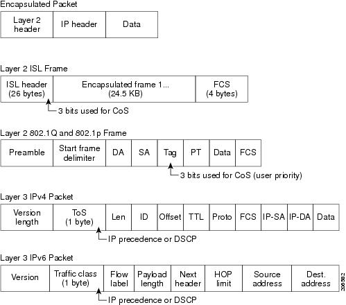
The classification is carried in the IP packet header using six bits from the deprecated IP Type of Service (ToS) field to carry the classification (class) information. Classification can also be carried in the Layer 2 frame.

The special bits in the Layer 2 frame or a Layer 3 packet are shown in this figure:

Figure 1. Classification layers of QoS in frames and packets

Layer 3 packet prioritization bits

Layer 3 IP packets can carry an IP Precedence value or a DSCP value. QoS supports the use of either value because DSCP values are backward-compatible with IP precedence values.

IP precedence values range from 0 to 7. DSCP values range from 0 to 63.

How QoS uses classification

All switches and routers accessing the internet rely on class information. A switch provides the same forwarding treatment to packets with identical class information and different treatment to packets with varying class information. The class information in the packet can be assigned by end hosts or by switches or routers along the way, based on a configured policy, detailed examination of the packet, or both. It is expected that detailed examination of the packet will occur closer to the edge of the network, avoiding overload for the core switches and routers.

Switches and routers along the path can use the class information to limit the amount of resources allocated per traffic class. The behavior of an individual device when handling traffic inthe Diff-Serv architecture is called per-hop behavior. If all the devices along a path provide a consistent per-hop behavior, you can construct a complete QoS solution.

Implementing QoS in your network can be simple or complex, depending on the features offered by your internetworking devices, the types and patterns of traffic in your network, and the level of control you need over incoming and outgoing traffic.

Packet classification

Packet classification is the process of identifying a packet as belonging to one of several classes in a defined policy, based on certain criteria. The MQC is a policy-class based language.

The policy class language is used to define these:

  • Class map template with one or several match criteria

  • Policy map template with one or several classes associated to the policy map

The policy map template is then associated to one or several interfaces on the device. Packet classification is the process of identifying a packet as belonging to one of the classes defined in the policy map. The process of classification will exit when the packet being processed matches a specific filter in a class. This is referred to as first-match exit. If a packet matches multiple classes in a policy, irrespective of the order of classes in the policy map, it will still exit the classification process after matching the first class.

If a packet does not match any of the classes in the policy, it is classified into the default class in the policy. Every policy map has a default class, which is a system-defined class to match the packets that do not match any of the user-defined classes.

Packet classification can be categorized into these types:

  • Classification based on information that is propagated with the packet

  • Classification based on information that is device specific

  • Hierarchical classification (on Cisco C9350 series smart switches)

Classification based on packet propagated information

Classification based on information that is part of a packet, and propagated either end-to-end or between hops, typically includes these:

  • Classification based on Layer 3 or 4 headers

  • Classification based on Layer 2 information

Classification based on Layer 3 or Layer 4 header

This is the most common deployment scenario. Numerous fields in the Layer 3 and Layer 4 headers can be used for packet classification.

At the most granular level, this classification methodology can be used to match an entire flow. For this deployment type, an access control list (ACL) can be used. ACLs can also be usedbased on various subsets of the flow, for example, source IP address only, destination IP address only, or a combination of both.

Classification can also be done based on the precedence or DSCP values in the IP header. The IP precedence field is used to indicate the relative priority with which a particular packet needs to be handled. It is made up of three bits in the IP header's type of service (ToS) byte.

This table shows the different IP precedence bit values and their names.

Table 8. IP precedence values and names

IP precedence value

IP precedence bits

IP precedence names

0 000 Routine
1 001 Priority
2 010 Immediate
3 011 Flash
4 100 Flash override
5 101 Critical
6 110 Internetwork control
7 111 Network control

Note


All the routing control traffic in a network use the IP precedence value 6 by default. IP precedence value 7 is also reserved for network control traffic. Therefore, we do not recommend the use of IP precedence values 6 and 7 for user traffic.


The DSCP field is made up of 6 bits in the IP header, and is being standardized by the IETF Differentiated Services working goup. The original ToS byte, which contained the DSCP bits, has been renamed the DSCP byte.

The DSCP field is part of the IP header, similar to IP precedence. The DSCP field is a super set of the IP precedence field. Therefore, the DSCP field is used and is set in ways that are similar to what was described with respect to IP precedence.


Note


The DSCP field definition is backward-compatible with the IP precedence values. Some fields in the Layer 2 header can also be set using a policy.


Classification based on Layer 2 header

The CoS method can be used to perform classification based on the Layer 2 header information. Classification is based on the three bits in the Layer 2 header based on the IEEE 802.1p standard. This usually maps to the ToS byte in the IP header.

Classification based on device specific information

A device also provides classification mechanisms in scenarios that are available where classification is not based on information in the packet header or payload.

At times you might be required to aggregate traffic coming from multiple input interfaces into a specific class in the output interface. For example, multiple customer edge routers might be going into the same access device on different interfaces. The service provider might want to police all the aggregate voice traffic going into the core to a specific rate. However, the voice traffic coming in from the different customers could have different ToS settings. QoS group-based classification is a feature that is useful in these scenarios.

Policies configured on the input interfaces set the QoS group to a specific value, which can then be used to classify the packets in the policies enabled on the output interface.

The QoS group is a field in the packet data structure that is internal to a device. It is important to note that a QoS group is an internal label to the device and is not a part of the packet header.

QoS prerequisites

To implement QoS, the device must perform these tasks:

  • Traffic classification: Distinguish packets or flows from one another.

  • Traffic marking and policing: Assign a label to indicate the given quality of service as the packets move through the device, and then make the packets comply with the configured resource usage limits.

  • Queuing and scheduling: Provide various treatments where resource contention exists.

  • Shaping: Ensure the sent traffic meets a specific profile.

  • Ingress port activity: Activities that occur at the ingress port of a device:

    • Classification: Classifying a distinct path for a packet by associating it with a QoS label. For instance, the device maps the CoS or DSCP in the packet to a QoS label to distinguish different types of traffic. The QoS label that is generated identifies all future QoS actions to be performed on this packet.

    • Marking: Marking evaluates the policer and decides what to do with a packet: pass it through without modification, mark down the QoS label, or drop it. Traffic can be marked with traffic-class to hit a particular VoQ. Marking can also be done without policing.

  • Egress ort activity: Activities that occur at the egress port of a device:

    • Policing: Policing is not supported for outgoing packets.

    • Marking: Marking rewrites the QoS tags such as DSCP and CoS in the packet so that the next hop can apply QoS based on the new value. You must configure a separate policy-map and use the service-policy output policy-name command to attach it to the egress direction of an interface. It is different from the type queueing policy-map described in the next bullet point. This policy-map can only contain marking action using the set qos-tag value command. For example, set dscp cs6 or set cos 5.

    • Queuing: Queuing selects which VoQ to use, and applies congestion management such as queue-limit and random-detect. Packets admitted into VoQ are scheduled to the corresponding egress output queueing. Shape, priority, and bandwidth remaining ratio affects how packets are scheduled. VoQ selection happens on the ingress side by setting the traffic-class in the ingress policy if configured, or it follows the default QoS tag to traffic-class mapping which only uses traffic-class 0 and 7. On the egress side, a separate type queueing policy-map can be attached to the interface unless the default queuing configuration is acceptable. This policy-map can only use class-maps that match traffic-class (class-default matches traffic-class 0 by default). The service-policy type queueing output policy-name command is used to attach the queuing policy-map to an interface. The policy-name used must be a policy-name defined using the policy-map type queueing command.

QoS limitations

This section list the limitations of QoS feature.

Limitations on wired targets

  • Queueing:

    • Max 8 queuing classes per port for a wired target.

    • Only 8 output queues per port supported.

    • Queue-limit range varies between SUP-3 and SUP-3XL.

  • Policing (non-queueing policy map):

    • Policer supported only on ingress.

    • Upto 32 policers per ingress policy map per port.

    • Each policer tracks conform, exceed, and violate counters.

  • Policy maps:

    • Max 1599 policy maps and 16 unique policy maps per device.

    • Max 256 classes per policy on a wired port.

  • Priority levels on Cisco C9350 series smart switches:

    • 8 priority levels (0–7) supported.

    • Only one priority level per class map; default is 0 (nonpriority).

  • Priority levels on Cisco C9610 series smart switches:

    • Only 2 priority levels supported.

    • Only one priority level per class map; default is 0 (nonpriority).

    • Traffic class 7 should always be configured with priority level 1, and traffic class 6 can be either priority level 2 or non-priority. Priority level 2 cannot be used with any other traffic class.

    • Multicast traffic can be shaped on priority classes. Shaping does not take any impact on non-priority queues for multicast traffic.

  • Hierarchical QoS (HQoS): Applicable only to Cisco C9350 series smart switches.

    • No overlapping actions between parent and child (except port shaper in parent and queuing in child).

    • Policing or marking can only be configured in parent or child, not both.

    • For ingress HQoS, only parent-level policing is supported.

    • Empty classes are allowed.

  • Marking:

    • Not supported in egress type queuing policy.

    • Egress remarking requires a new policy map (DSCP, PREC, CoS, MPLS EXP, or QoS-group based only, not ACL).

    • No DSCP to CoS, CoS to precedence, or similar table maps (must be of the same QoS type).

  • Classification counters:

    • Port-based only; no aggregation.

    • Packets, not bytes are counted.

    • Triggered only by marking or policing actions.

    • Ingress: 32 unique counters/port

    • Egress: 8 unique counters/port; extra classes share counters.

    • Counter is cumulative for all matches in a class.

  • Classification not supported for:

    • VPLS

    • Layer 2/MAC

    • VLAN ID

    • Protocol types

    • Packet length (fixed/range)

    • RTP header/type

    • Egress side ACLs

    • IPv6 ACE with TCP flag

    • Object group-based ACLs

    • App-ID metadata

    • Security Group Tag (SGT) aware QoS

    • StackWise Virtual Link (SVL) QoS

  • Policing:

    • Not supported in egress direction.

    • Not supported on SVI, tunnel interfaces, and member ports of Layer 2 or Layer 3 port-channel interface.

    • Aggregate policing for egress not supported.

  • Queueing:

    • Supported only on Traffic Class (TC) based classification.

    • Not supported on SVI, port channel interface, and tunnel interface.

    • No Application Visibility and Control (AVC) or NBAR based QoS.

  • Table maps:

    • Only one table-map for exceed, one for violate markdown per switch/stack.

    • Max 15 unique combinations of exceed/violate table maps supported.

    • All classes in a policy map must use the same table-map for exceed/violate.

  • Egress remarking:

    • Not supported with ACL-based classification.

    • Only supported via DSCP, CoS, precedence, or MPLS EXP (new policy map required).

  • GRE tunnels:

    • Policy map can only be attached to physical members, not logical tunnel interfaces.

    • GRE policing and marking not supported.

  • LISP QoS:

    • Not supported.

  • QoS ACL TCAM for egress:

    • Not supported.

  • BUM (Broadcast, Unknown Unicast, Multicast) traffic:

    • Limited visibility in show policy-map type queue interface.

    • Only 2 output queue stats for multicast.

Limitations on EtherChannel and channel member interfaces

  • Queuing policy:

    • Supported only on EtherChannel member ports.

    • You can apply a queuing-type service policy to individual member ports of an EtherChannel.

  • Non-queuing policy:

    • Supported only on the EtherChannel interface itself.

    • Non-queuing (example: policing, marking) policies must be applied to the Port-Channel (logical) interface, not to the individual member ports.

  • Policy rejection:

    • If you attempt to apply a non-queuing service policy to a channel member port, the configuration is rejected with a message:

      Only queueing type policy is supported on member interfaces.

Limitations on egress queuing policy

  • Single traffic class per class-map: Each class-map in a queuing policy can only match one traffic class (range: 0–7).

  • Class-default: Always matches traffic class 0. No other class-map can match traffic class 0.

  • No set traffic-class: If an ingress policy map does not include a set traffic-class action, the QoS tag is mapped to traffic class 0 or 7 by default.

  • Override system default: To use non-default queues, configure the set traffic-class action in the ingress policy map. This setting influences Virtual Output Queue (VOQ) selection for all egress ports.

  • Profile limit: Each unique combination of traffic classes in a queuing policy-map requires its own profile.

  • Max Profiles: Only eight traffic class profiles are supported for main interfaces.

  • Packet drop stats:

    • Packet drop statistics for multicast and Layer 2 traffic dropped due to queuing policer (shape limit exceeded) are not displayed in total packet drop stats on the interface.

    • Only unicast drop statistics are shown.

  • Priority mapping: Each configured priority level must be set in the class that matches the corresponding traffic class.

Supported actions in queuing policy

Only these actions are supported within a queuing policy map:

  • priority

  • shape

  • bandwidth remaining ratio

  • queue-limit

  • random early detection (RED)

Configure Class, Policy, and Maps

This section provides configuration information about class, policy, and maps.

Create a traffic class

Before you begin

All match commands specified in this configuration task are considered optional, but you must configure at least one match criterion for a class.


Note


Define individual class-maps for different types of QoS tag values. You cannot match a traffic-class with two different traffic-class values in the same class-map. For example, you cannot add DSCP, PRE, or CoS matching to a class-map that already includes a traffic-class match.


To create a traffic class containing match criteria, use the class-map command to specify the traffic class name, and then use the following match commands in class-map configuration mode, as needed.

Procedure

  Command or Action Purpose

Step 1

configure terminal

Example:


Device# configure terminal

Enters global configuration mode.

Step 2

class-map class-map name {match-any | match-all}

Example:


Device(config)# class-map test_1000
Device(config-cmap)#

Enters class map configuration mode.

  • Creates a class map to be used for matching packets to the class whose name you specify.

  • match-any : Any one of the match criteria must be met for traffic entering the traffic class to be classified as part of it.

  • match-all : All of the match criteria must be met for traffic entering the traffic class to be classified as part of the traffic class.

    Note


    This is the default. If match-any or match-all is not explicitly defined, match-all is chosen by default.

Step 3

match access-group name

Example:


Device(config-cmap)# match access-group 100
Device(config-cmap)#

The following parameters are available for this command:

  • access-group

  • cos

  • dscp

  • ip

  • mpls

  • precedence

  • qos-group

  • traffic-class

Step 4

match cos cos value

Example:


Device(config-cmap)# match cos 2 3 4 5
Device(config-cmap)#

(Optional) Matches IEEE 802.1Q or ISL class of service (user) priority values.

  • Enters up to 4 CoS values separated by spaces (0 to 7).

Step 5

match dscp dscp value

Example:


Device(config-cmap)# match dscp af11 af12
Device(config-cmap)#

(Optional) Matches the DSCP values in IPv4 and IPv6 packets.

Step 6

match ip {dscp dscp value | precedence precedence value}

Example:


Device(config-cmap)# match ip dscp af11 af12
Device(config-cmap)#

(Optional) Matches IP values including the following:

  • dscp : Matches IP DSCP (DiffServ codepoints).

  • precedence : Matches IP precedence (0 to 7).

    Note


    Because CPU-generated packets are not marked at egress, these packets do not match the configured class-map.

Step 7

match mpls experimental experimental value

Example:


Device(config-cmap)# match mpls experimental topmost 3
Device(config-cmap)#

(Optional) Match MPLS experimental valueon top most label (from 0 to 7).

Step 8

match qos-group qos group value

Example:


Device(config-cmap)# match qos-group 10
Device(config-cmap)#

(Optional) Matches QoS group value (from 0 to 31).

Step 9

match traffic-class traffic-class value

Example:


Device(config-cmap)# match traffic-class 7
Device(config-cmap)#

(Optional) Matches QoS traffic class value (from 1 to 7).

Step 10

end

Example:


Device(config-cmap)# end

Saves the configuration changes.

What to do next

Configure the policy map.

Create a traffic policy

Before you begin

You should have first created a class map.

To create a traffic policy, use the policy-map global configuration command to specify the traffic policy name.

The traffic class is associated with the traffic policy when the class command is used. The class command must be entered after you enter the policy map configuration mode. After entering the class command, the device is automatically in policy map class configuration mode, which is where the QoS policies for the traffic policy are defined.

The following policy map class-actions are supported:

  • exit: Exits from the QoS class action configuration mode.

  • no: Negates or sets default values for the command.

  • police: Policer configuration options.

  • service-policy: Configures the QoS service policy.

  • set: Sets QoS values using the following options:

    • CoS values

    • Discard-class values

    • DSCP values

    • IP values

    • MPLS exp values

    • Precedence values

    • QoS group values

    • Traffic class values


    Note


    If the set option is not used in the egress policy to remark egress traffic, the statistics of the policy will not be displayed when you use the show policy-map interface command.


Procedure

  Command or Action Purpose

Step 1

configure terminal

Example:


Device# configure terminal

Enters global configuration mode.

Step 2

policy-map policy-map name

Example:


Device(config)# policy-map test_2000
Device(config-pmap)#

Enters policy map configuration mode.

Creates or modifies a policy map that can be attached to one or more interfaces to specify a service policy.

Step 3

class {class-name | class-default}

Example:


Device(config-pmap)# class test_1000
Device(config-pmap-c)#

Specifies the name of the class whose policy you want to create or change.

You can also create a system default class for unclassified packets.

Step 4

police {target_bit_rate | cir | rate}

Example:


Device(config-pmap-c)# police 10000000
Device(config-pmap-c)#

(Optional) Configures the policer:

  • target_bit_rate : Enter the bit rate per second, enter a value between 1200000 and 400000000000.

  • cir : Committed Information Rate.

  • rate : Specify police rate, PCR for hierarchical policies or SCR for single-level ATM 4.0 policer policies.

Step 5

service-policy policy-map name

Example:


Device(config-pmap-c)# service-policy test_2000
Device(config-pmap-c)#

(Optional) Configures the QoS service policy.

Step 6

set {cos | discard-class | dscp | ip | mpls | precedence | qos-group | traffic-class}

Example:


Device(config-pmap-c)# set cos 7
Device(config-pmap-c)#

(Optional) Sets the QoS values. Possible QoS configuration values include:

  • cos : Sets the IEEE 802.1Q/ISL class of service/user priority.

  • discard-class : Sets discard behavior identifier.

  • dscp : Sets DSCP in IP(v4) and IPv6 packets.

  • ip : Sets IP specific values.

  • mpls : Sets MPLS specific values.

  • precedence : Sets precedence in IP(v4) and IPv6 packet.

  • qos-group : Sets the QoS Group.

  • traffic-class : Sets the traffic class.

Step 7

end

Example:


Device(config-pmap-c) #end
Device(config-pmap-c) #

Saves the configuration changes.

What to do next

Configure the interface.

Create a traffic queueing policy

To create a traffic queueing policy for QoS, perform this procedure.

The following queueing policy map class-actions are supported:

  • bandwidth: Bandwidth configuration options.

  • exit: Exits from the QoS class action configuration mode.

  • no: Negates or sets default values for the command.

  • priority: Configures strict scheduling priority for the class.

  • queue-limit: Queue threshold for tail drop configuration options.

  • random-detect: Enables Random Early Detection as drop policy.

  • service-policy: Configures QoS service policy.

  • shape: Traffic shaping configuration options.

Procedure

  Command or Action Purpose

Step 1

configure terminal

Example:


Device# configure terminal

Enters global configuration mode.

Step 2

policy-map type queueing policy name

Example:


Device(config)# policy-map type queueing test
Device(config-pmap)#

Enters policy map configuration mode.

Creates or modifies a policy map that can be attached to one or more interfaces to specify a service policy.

Step 3

class class name

Example:


Device(config-pmap)# class traffic-class7
Device(config-pmap-c)#

Enters policy class map configuration mode. Specifies the name of the class whose policy you want to create or change. Command options for policy class map configuration mode include the following:

  • word : Class map name.

  • class-default : System default class matching any otherwise unclassified packets.

Step 4

bandwidth remaining ratio ratio

Example:


Device(config-pmap-c)# bandwidth remaining ratio 10
Device(config-pmap-c)#

(Optional) Configures ratio for sharing excess bandwidth. The range is from 1 to 63.

Note

 
  • bandwidth remaining ratio and priority level cannot be configured simultaneously for the same class, even though they can be in the same policy.

  • Traffic class 7 must always be configured with priority level 1.

Step 5

priority level level

Example:


Device(config-cmap)# priority level 1 
Device(config-cmap)#

(Optional) Configures priority level queue.

Step 6

queue-limit value [bytes]

Example:


Device(config-cmap)# queue-limit 100000 bytes
Device(config-cmap)#

(Optional) Sets the queue limit threshold percentage value in bytes.

Step 7

random-detect {discard-class | discard-class-based | exponential-weighting-constant}

Example:


Device(config-cmap)# random-detect discard-class-based
Device(config-cmap)#

(Optional) Enables Random Early Detection as the drop policy.

  • discard-class : Parameters for each discard- class value (0 or 1).

    Note


    discard-class and priority cannnot be configured simultaneously for the same class, even though they can be in the same policy.

  • discard-class-based : Enables discard-class-based WRED as the drop policy.

  • exponential-weighting-constant : Weight for mean queue depth calculation (0 to 15).

Step 8

end

Example:


Device(config-cmap)# end

Exits class map configuration mode and returns to privileged EXEC mode.

Configure class-based packet marking for ingress policy-map

Before you begin

You should have created a class map and a policy map before beginning this procedure.

This procedure explains how to configure these class-based packet marking features on your device:

  • CoS value

  • Discard-class value

  • DSCP value

  • IP value

  • MPLS experimental value

  • Precedence value

  • QoS group value

  • Traffic-class value

Procedure

  Command or Action Purpose

Step 1

configure terminal

Example:


Device# configure terminal

Enters global configuration mode.

Step 2

policy-map policy name

Example:


Device(config)# policy-map policy1
Device(config-pmap)#

Enters policy map configuration mode.

Creates or modifies a policy map that can be attached to one or more interfaces to specify a service policy.

Step 3

class class name

Example:


Device(config-pmap)# class class-default
Device(config-pmap-c)#

Enters policy class map configuration mode. Specifies the name of the class whose policy you want to create or change.

Command options for policy class map configuration mode include these:

  • exit : Exits from the QoS class action configuration mode.

  • no : Negates orsets default values for the command.

  • police : Policer configuration options.

  • service-policy : Configures the QoS service policy.

  • set : Sets QoS values using these options:

    • CoS values

    • Discard-class values

    • DSCP values

    • IP values

    • MPLS values

    • Precedence values

    • QoS group values

    • Traffic class values

Note


This procedure describes the supported configurations using set command options. The other command options (bandwidth ) are described in other sections of this guide. Only one set command for QoS tag (CoS/DSCP/PREC/EXP) is supported per class. The same class can also have set traffic-class and/or set discard-class if it is a ingress policy.

Step 4

set cos {cos value | cos table table-map name | dscp table table-map name | precedence table-map name | qos-group table table-map name}

Example:


Device(config-pmap)# set cos cos table cos-mapping
Device(config-pmap)# 

(Optional) Sets the specific IEEE 802.1Q Layer 2 CoS value of an outgoing packet. Values are from 0 to 7.

You can also set the CoS values using a table map. This is a list of from types supported when using atable map. For example, set cos qos-group table table-map name means use the table-map to map from QoS-group to CoS.

  • cos table : Sets the CoS value based on a table map.

  • dscp table : Sets the CoS value from DSCP value based on a table map.

  • precedence table : Sets the CoS value from precedence value based on a table map.

  • qos-group table : Sets the CoS value from QoS group based on a table map.

Note

 
  • set cos qos-group table is only supported in egress policy.

  • Table-map is only supported in class-default.

Step 5

set discard-class {discard-class value | cos table table-map name | dscp table table-map name | mpls experimental imposition table table-map name | precedence table-map name}

Example:


Device(config-pmap)# set discard-class 0 
Device(config-pmap)#

(Optional) Sets discard-class values from 0 to 1. You can also set the discard-class values using a table map.

  • cos table : Sets the discard-class value from CoS value based on a table map.

  • dscp table : Sets the discard-class value from DSCP value based on a table map.

  • mpls experimental imposition table : Sets the discard-class value from MPLS experimental based on a table map.

  • precedence table : Sets the discard-class value from precedence value based on a table map.

Note

 
  • Table-map is only supported in class-default.

  • If the discard-class value is set to 1 and a policer is configured in the same class, the discard-class will not have any impact during congestion scenario, as policer (color blind) marks all confirmed packets as green.

Step 6

set dscp {dscp value | cos table table-map name | default | dscp table table-map name | ef | precedence table table-map name | qos-group table table-map name}

Example:


Device(config-pmap)# set dscp af11
Device(config-pmap)# 

(Optional) Sets the DSCP value. Values are from 0 to 63.

You can also set the DSCP values using a table map. This is a list of from types supported when using a table map.

For example, set dscp qos-group table table-map name means use the table- map to map from QoS-group to DSCP.

  • cos table : Sets the packet DSCP value from CoS value based on a table map.

  • dscp table : Sets the packet DSCP value from DSCP based on a table map.

  • precedence table : Sets the packet DSCP value from precedence based on a table map.

  • qos-group table : Sets the packet DSCP value from a QoS group based upon a table map.

Note


Table-map is only supported in class-default.

Step 7

set ip {dscp | precedence}

Example:


Device(config-pmap)# set ip dscp c3
Device(config-pmap)#

(Optional) Sets IP specific values. These values are either IP DSCP or IP precedence values.

You can also set the IP values using a table map. This is a list of from types supported when using a table map. For example, set qos-group dscp table table-map name means use the table-map to map from DSCP value to QoS-group.

Note


Table-map is only supported in class-default.

You can set these values using the set ip dscp command:

  • cos table : Sets the packet DSCP value from CoS value based on a table map.

  • dscp table : Sets the packet DSCP value from DSCP based on a table map.

  • precedence table : Sets the packet DSCP value from precedence based on a table map.

  • qos-group table : Sets the packet DSCP value from a QoS group based upon a table map.

This is a list of from types supported when using a table map. For example, set ip precedence qos-group table table-map name means use the table-map to map from QoS-group to IP precedence.

  • cos table : Sets the packet precedence value from CoS value based on a table map.

  • dscp table : Sets the packet precedence from DSCP value based on a table map.

  • precedence table : Sets the precedence value from precedence based on a table map.

  • qos-group table : Sets the precedence value from a QoS group based upon a table map.

Note


set ip precedence qos-group table table-mapname is only supported in egress.

Step 8

set mpls experimental {dscp table table-map name | imposition {experimental value | dscp table table-map name | precedence table table-map name} | precedence table table-map name | topmost {experimental value | cos table-map name | precedence table-map name | qos-group table-map name}}

Example:


Device(config-pmap)# set mpls experimental imposition 4
Device(config-pmap)#

(Optional) Sets the MPLS experimental values from 0 to 7. You can also set the MPLS values using a table map.

  • dscp table : Sets the MPLS experimental value from DSCP value on a table map.

  • precedence table : Sets the MPLS experimental value from precedence based on a table map.

  • cos table : Sets the MPLS experimental value from CoS value based on a table map.

  • qos-group table : Sets the MPLS experimental from a QoS group based upon a table map.

Step 9

set precedence {precedence value | cos table table-map name | dscp table table-map name | precedence table table-map name | qos-group table table-map name | traffic-class table table-map name}

Example:


Device(config-pmap)# set precedence 5
Device(config-pmap)#

(Optional) Sets precedence values in IPv4 and IPv6 packets. Values are from 0 to 7.

You can also set the precedence values using a table map. This is a list of from types supported when using a table map. For example, set precedence qos-group table table-mapname means use the table-map to map from QoS-group to precedence.

  • cos table : Sets the packet precedence value from CoS value based on a table map.

  • dscp table : Sets the packet precedence value from DSCP value on a table map.

  • precedence table : Sets the precedence value from precedence based on a table map.

  • qos-group table : Sets the precedence value from a QoS group based upon a table map.

Note


Table-map is only supported in class-default.

Step 10

set qos-group {qos-group value | cos table table-map name | dscp table table-map name | ip-precedence | mpls experimental table table-map name | precedence table table-map name}

Example:


Device(config-pmap)# set qos-group 10
Device(config-pmap)#

(Optional) Sets QoS group values from 0 to 30. You can also set the QoS group using a table map.

  • cos table : Sets QoS group from CoS value based on a table map.

  • dscp table : Sets QoS group from DSCP value based on a table map.

  • mpls experimental table : Sets QoS group from MPLS experimental value based on a table map.

  • precedence table : Sets QoS group from precedence based on a table map.

Step 11

set traffic-class {traffic-class value | cos table table-map name | dscp table table-map name | mpls experimental imposition table table-map name | precedence table table-map name}

Example:


Device(config-pmap)# set traffic-class 3
Device(config-pmap)#

(Optional) Sets traffic-class values from 0 to 7, or from these table-maps:

  • cos table : Sets the traffic-class value from COS value based on a table map.

  • dscp table : Sets the traffic-class valuefrom DSCP value based on a tablemap.

  • mpls experimental imposition table : Sets the traffic-class value from MPLS experimental value based on a table map.

  • precedence table : Sets the traffic-class value from precedence based on a table map.

Step 12

end

Example:


Device(config-pmap)# end
Device#

Exits policy map configuration mode and returns to privileged EXEC mode.

Step 13

show policy-map

Example:


Device# show policy-map

(Optional) Displays policy configuration information for all classes configured for all service policies.

What to do next

Attach the traffic policy to an interface using the service-policy command.

Attach a traffic policy to an interface

Before you begin

A traffic class and traffic policy must be created before attaching a traffic policy to an interface.

After the traffic class and traffic policy are created, you must use the service-policy interface configuration command to attach a traffic policy to an interface, and to specify the direction in which the policy should be applied (either on packets coming into the interface or packets leaving the interface).

Procedure

  Command or Action Purpose

Step 1

configure terminal

Example:


Device# configure terminal

Enters global configuration mode.

Step 2

interface type

Example:


Device(config)# interface HundredGigE4/0/1
Device(config-if)#

Enters interface configuration mode and configures an interface.

Command parameters for the interface configuration include:

  • TenGigabitEthernet : 10-Gigabit Ethernet

  • FiftyGigabitEthernet : 50-Gigabit Ethernet

  • HundredGigabitEthernet : 100-Gigabit Ethernet

  • FourHundredGigabitEthernet : 400-Gigabit Ethernet

Note

 
  • Tunnel and VLAN interface is not supported.

  • Policing, queuing, and marking are not supported on the management interface.

Step 3

service-policy [type queueing] {input policy-map | output policy-map}

Example:


Device(config-if)# service-policy output policy_map_01
Device(config-if)#

Attaches a policy map to an input or output interface. This policy map is then used as the service policy for that interface.

In this example, the traffic policy evaluates all traffic leaving that interface.

Note

 
  • Non-queuing policy with policer is supported only in ingress.

  • On egress, only non-queueing policy with marking is supported.

  • Queuing policy (type queueing ) is supported only in egress.

  • Meter police should be applied in ingress direction and remark police should be applied in egress direction.

Step 4

end

Example:


Device(config-if)# end
Device#

Exits interface configuration mode and returns to privileged EXEC mode.

Step 5

show policy-map

Example:


Device# show policy-map

(Optional) Displays statistics for the policy on the specified interface.

What to do next

Proceed to attach any other traffic policy to an interface, and to specify the direction in which the policy should be applied.

Classify, police, and mark traffic on physical ports by using policy maps

Before you begin

You should have already decided upon the classification, policing, and marking of your network traffic by policy maps prior to beginning this procedure.

You can configure a nonhierarchical policy map on a physical port that specifies which traffic class to act on. Actions supported are remarking and policing.

Procedure

  Command or Action Purpose

Step 1

configure terminal

Example:


Device# configure terminal

Enters global configuration mode.

Step 2

class-map {class-map name | match-any | match-all}

Example:


Device(config)# class-map ipclass1
Device(config-cmap)# exit
Device(config)#

Enters class-map configuration mode.

  • Creates a class-map to be used for matching packets to the class whose name you specify.

  • If you specify match-any , one of the match criteria must be met for traffic entering the traffic class to be classified as part of the traffic class. This is the default.

  • If you specify match-all , all of the match criteria must be met for traffic entering the traffic class to be classified as part of the traffic class.

    Note


    This is the default. If match-any or match-all is not explicitly defined, match-all is chosen by default.

Step 3

match access-group access list name

Example:


Device(config-cmap)# match access-group acl
Device(config-cmap)# exit
Device(config)#

The following parameters are available for this command:

  • access-group

  • cos

  • dscp

  • ip

  • precedence

  • qos-group

Step 4

policy-map policy-map-name

Example:


Device(config)# policy-map ipclass1
Device(config-pmap)#

Creates a policy map by entering the policy map name, and enters policy-map configuration mode.

By default, no policy maps are defined.

Step 5

class {class-map-name | class-default}

Example:


Device(config-pmap)# class ipclass1
Device(config-pmap-c)# 

Defines a traffic classification, and enter policy-map class configuration mode.

By default, no policy map class-maps are defined.

If a traffic class has already been defined by using the class-map global configuration command, specify its name for class-map-name in this command.

A class-default traffic class is predefined and can be added to any policy. It is always placed at the end of a policy map. With an implied match any included in the class-default class, all packets that have not already matched the other traffic classes will match class-default .

Step 6

set {cos | discard-class | dscp | ip | mpls | precedence | qos-group | traffic-class}

Example:


Device(config-pmap-c)# set dscp 45
Device(config-pmap-c)#

(Optional) Sets the QoS values. Possible QoS configuration values include:

  • cos : Sets the IEEE 802.1Q/ISL class of service/user priority.

  • discard-class : Sets discard behavior identifier.

  • dscp : Sets DSCP in IP(v4)and IPv6 packets.

  • ip : Sets IP specific values.

  • mpls : Sets MPLS specific values.

  • precedence : Sets precedence in IP(v4) and IPv6 packet.

  • qos-group : Sets the QoS group.

  • traffic-class : Sets the traffic class.

In this example, the set dscp command classifies the IP traffic by setting a new DSCP value in the packet.

Step 7

police {target_bit_rate | cir | rate}

Example:


Device(config-pmap-c)# police 1200000 conform-action transmit exceed-action drop
Device(config-pmap-c)#

(Optional) Configures the policer:

  • target_bit_rate : Specifies the bit rate per second, enter a value between 1200000 and 400000000000.

  • cir : Committed Information Rate.

  • rate : Specifies the police rate PCR for hierarchical policies.

In this example, the police command adds a policer to the class where any traffic beyond the 1200000 set target bit rate is dropped.

Step 8

exit

Example:


Device(config-pmap-c)# exit

Returns to policy map configuration mode.

Step 9

exit

Example:


Device(config-pmap)# exit

Returns to global configuration mode.

Step 10

interface interface-id

Example:


Device(config)# interface HundredGigE 1/0/2

Specifies the port to attach to the policy map, and enters interface configuration mode.

Valid interfaces include physical ports.

Step 11

service-policy input policy-map-name

Example:


Device(config-if)# service-policy input ipclass1

Specifies the policy-map name, and applies it to an ingress port. Only one policy map per ingress port is supported.

Step 12

end

Example:


Device(config-if)# end

Returns to privileged EXEC mode.

Step 13

show policy-map [policy-map-name [class class-map-name]]

Example:


Device# show policy-map ipclass1

(Optional) Verifies your entries.

Step 14

copy running-config startup-config

Example:


Device# copy-running-config startup-config

(Optional) Saves your entries in the configuration file.

Classify and mark traffic by using policy maps

Before you begin

You should have already decided upon the classification, policing, and marking of your network traffic by using policy maps prior to beginning this procedure.

Procedure

  Command or Action Purpose

Step 1

configure terminal

Example:


Device# configure terminal

Enters global configuration mode.

Step 2

class-map {class-map name | match-any | match-all}

Example:


Device(config)# class- map class_cos2 
Device(config-cmap)# match cos 2

Enters class map configuration mode.

  • Creates a class map to be used for matching packets to the class whose name you specify.

  • If you specify match-any , one of the match criteria must be met for traffic entering the traffic class to be classified as part of the traffic class.

  • If you specify match-all , all of the match criteria must be met for traffic entering the traffic class to be classified as part of the traffic class.

    Note


    This is the default. If match-any or match-all is not explicitly defined, match-all is chosen by default.

Step 3

policy-map policy-map-name

Example:


Device(config)# policy-map policy_cos2
Device(config-pmap)#

Creates a policy map by entering the policy map name, and enters policy-map configuration mode.

By default, no policy maps are defined.

Step 4

description description

Example:


Device(config-pmap)# description cos 2

(Optional) Enters a description of the policy map.

Step 5

class {class-map-name | class-default}

Example:


Device(config-pmap)# class class_cos2
Device(config-pmap-c)# 

Defines a traffic classification, and enters the policy-map class configuration mode.

By default, no policy map class-maps are defined.

If a traffic class has already been defined by using the class-map global configuration command, specify its name for class-map-name in this command.

A class-default traffic class is predefined and can be added to any policy. It is always placed at the end of a policy map. With an implied match any included in the class-default class, all packets that have not already matched the other traffic classes will match class-default .

Step 6

set {cos | qos-group | traffic-class | discard-class}

Example:


Device(config-pmap-c)# set cos 7
Device(config-pmap-c)#

(Optional) Sets the QoS values. Possible QoS configuration values include:

  • cos : Sets the IEEE 802.1Q/ISL class of service/user priority.

  • qos-group : Sets QoS group.

  • traffic-class : Sets traffic class.

  • discard-class : Sets discard class.

In this example, the set cos command classifies the traffic by matching the packets with a COS values of 2, and sets the CoS value to a new value of 7.

Step 7

exit

Example:


Device(config-pmap-c)# exit

Returns to policy map configuration mode.

Step 8

exit

Example:


Device(config-pmap)# exit

Returns to global configuration mode.

Step 9

interface interface-id

Example:


Device(config)# interface HundredGigE1/0/3

Specifies the port to attach to the policy map, and enters interface configuration mode.

Valid interfaces include physical ports, which should be a trunk port for Layer 2 based classification.

Step 10

service-policy input policy-map-name

Example:


Device(config-if)# service-policy 
input policy_vlan100

Specifies the policy-map name, and applies it to an ingress port. Only one policy map per ingress port is supported.

Step 11

end

Example:


Device(config-if)# end

Returns to privileged EXEC mode.

Step 12

show policy-map [policy-map-name [class class-map-name]]

Example:


Device# show policy-map

(Optional) Verifies your entries.

Step 13

copy running-config startup-config

Example:


Device# copy-running-config startup-config

(Optional) Saves your entries in the configuration file.

Configure table maps

Table maps area form of marking, and also enable the mapping and conversion of one field to another using a table. For example, a table map can be used to map and convert a Layer 2 CoS setting to a new or same CoS value, and also convert a Layer 2 CoS setting to a traffic class or a QoS group. Similar settings apply to Layer 3 DSCP and Precedence.

When setting a table-map in a policy, the from and to values should be of the same type, example DCSP to DSCP, COS to COS, and so on. This exception is not applicable for QoS- group and traffic-class where from and to values are of different types, for example, DSCP to traffic-class, COS to traffic-class, and so on.


Note


  • A table map can be referenced in multiple policies or multiple times in the same policy.

  • The examples in this procedure uses table maps to map DSCP value to traffic-class.


Procedure

  Command or Action Purpose

Step 1

configure terminal

Example:


Device# configure terminal

Enters global configuration mode.

Step 2

table-map name {default {default value | copy | ignore} | exit | map {from from value to to value } | no}

Example:


Device(config)# table-map table01
Device(config-tablemap)# 

Creates a table map and enters the table map configuration mode. In table map configuration mode, you can perform the following tasks:

  • default : Configures the table map default value, or sets the default behavior for a value not found in the table map to copy or ignore.

  • exit : Exits from the table map configuration mode.

  • map : Maps a from to a to value in the table map.

  • no : Negates or sets the default values of the command.

Step 3

map from value to value

Example:


Device(config-tablemap)# map from 0 to 2
Device(config-tablemap)# map from 1 to 4
Device(config-tablemap)# map from 24 to 3
Device(config-tablemap)# map from 40 to 6 
Device(config-tablemap)# default 0
Device(config-tablemap)#

In this step, packets with DSCP value 0 are marked to the traffic-class 2, DSCP value 1 to the traffic-class 4, DSCP value 24 to the traffic-class 3, DSCP value 40 to the traffic-class 6 and all others to the traffic-class 0.

Note


The mapping from DSCP to traffic-class values in this example is configured by using the set policy map class configuration command as described in a later step in this procedure.

Step 4

exit

Example:


Device(config-tablemap)# exit
Device(config)#

Returns to global configuration mode.

Step 5

exit

Example:


Device(config) exit
Device#

Returns to privileged EXEC mode.

Step 6

show table-map

Example:


Device# show table-map
Table Map table01
    from 0 to 2
    from 1 to 4
    from 24 to 3
    from 40 to 6
    default 0

Displays the table map configuration.

Step 7

configure terminal

Example:


Device# configure terminal
Device(config)#

Enters global configuration mode.

Step 8

policy-map

Example:


Device(config)# policy-map table-policy
Device(config-pmap)#

Configures the policy map for the table map.

Step 9

class class-default

Example:


Device(config-pmap)# class  class-default
Device(config-pmap-c)#

Matches the class to the system default.

Step 10

set traffic-class dscp table table map name

Example:


Device(config-pmap-c)# set traffic-class dscp table table01
Device(config-pmap-c)#

Incoming packets with DSCP value are mapped to hit a particular VOQ which is defined by the traffic-class values in a table-map.

Step 11

end

Example:


Device(config-pmap-c)# end
Device#

Returns to privileged EXEC mode.

What to do next

Configure any additional policy maps for QoS for your network. After creating your policy maps, attach the traffic policy or polices to an interface using the service-policy command.

Configure QoS functions

The following sections provide configurational information about QoS features and functionality.

Configure bandwidth

Before you begin

You should have created a created a class-map for bandwidth based on traffic-class classification before beginning this procedure.

This procedure explains how to configure bandwidth on your device.

Procedure

  Command or Action Purpose

Step 1

configure terminal

Example:


Device# configure terminal

Enters global configuration mode.

Step 2

policy-map type queueing policy name

Example:


Device(config)# policy-map type queueing policy_bandwidth01
Device(config-pmap)#

Enters policy map configuration mode.

Creates or modifies a policy map that can be attached to one or more interfaces to specify a service policy.

Step 3

class class name

Example:


Device(config-pmap)# class class_bandwidth01
Device(config-pmap-c)#

Enters policy class map configuration mode. Specifies the name of the class whose policy you want to create or change. Command options for policy class map configuration mode include the following:

  • word : Class map name.

  • class-default : In type queueing policy, class-default always matches traffic-class 0.

Step 4

bandwidth remaining ratio ratio

Example:


Device(config-pmap-c)# bandwidth remaining ratio 10
Device(config-pmap-c)#

Configures the bandwidth for the policy map.

  • ratio : Ratios can range from 1 to 63.

Note


Bandwidth command is applicable from traffic class 6 to traffic class 0 classification and should not be defined with priorities.

Step 5

end

Example:


Device(config-pmap-c)# end
Device#

Saves configuration changes.

Step 6

show policy-map

Example:


Device# show policy-map

(Optional) Displays policy configuration information for all classes configured for all service policies.

What to do next

Configure any additional policy maps for QoS for your network. After creating the policy maps, attach the traffic policy or polices to an interface using the service-policy command.

Configure police

Before you begin

You should have created a class map for policing before beginning this procedure.

This procedure explains how to configure policing on your device.

Procedure

  Command or Action Purpose

Step 1

configure terminal

Example:


Device# configure terminal

Enters global configuration mode.

Step 2

policy-map policy name

Example:


Device(config)# policy-map policy_police01
Device(config-pmap)#

Enters policy map configuration mode.

Creates or modifies a policy map that can be attached to one or more interfaces to specify a service policy.

Step 3

class class name

Example:


Device(config-pmap)# class class_police01
Device(config-pmap-c)#

Enters policy class map configuration mode. Specifies the name of the class whose policy you want to create or change. Command options for policy class map configuration mode include the following:

  • word : Class map name.

  • class-default : System default class matching any otherwise unclassified packets.

Step 4

police {target_bit_rate [conform-action | pir ] | cir {target_bit_rate | percent percentage} | rate {target_bit_rate | percent percentage} conform-action transmit exceed-action {drop [violate action] | set-cos-transmit | set-dscp-transmit | set-prec-transmit | transmit [violate action]}}

Example:


Device(config-pmap-c)# police 1200000 conform-action transmit exceed-action drop
Device(config-pmap-c)# 

The following police subcommand options are available:

  • target_bit_rate : Bits per second (from 1200000 to 400000000000).

    • conform-action : Action taken when rate is less than conform burst.

    • pir : Peak Information Rate.

  • cir : Committed Information Rate.

    • target_bit_rate : Target bit rate (from 1200000 to 400000000000).

    • percent : Percentage of interface bandwidth for CIR.

  • rate : Specifies the police rate, PCR for hierarchical policies, or SCR for single-level ATM 4.0 policer policies.

    • target_bit_rate : Target bit rate (from 1200000 to 400000000000).

    • percent : Percentage of interface bandwidth for rate.

The following police conform-action transmit exceed-action subcommand options are available:

  • drop : Drops the packet.

  • set-cos-transmit : Sets the CoS value and sends it.

  • set-discard-class- transmit : Sets the discard-class value and sends it.

  • set-dscp-transmit : Sets the DSCP value and sends it.

  • set-prec-transmit : Rewrites the packet precedence and sends it.

  • transmit : Transmits the packet.

Note


Policer-based markdown actions are only supported using table maps. Only one markdown table map is allowed for each marking field in the device.

Step 5

end

Example:


Device(config-pmap-c)# end
Device#

Saves configuration changes.

Step 6

show policy-map

Example:


Device# show policy-map

(Optional) Displays policy configuration information for all classes configured for all service policies.

Note


The show policy-map command output does not display counters for conformed bytes and exceeded bytes

What to do next

Configure any additional policy maps for QoS for your network. After creating your policy maps, attach the traffic policy or polices to an interface using the service-policy command.

Configure priority

Before you begin

You should have created a class map for priority before beginning this procedure.

This procedure explains how to configure priority on your device.


Note


The device supports giving priority to specified queues.


Procedure

  Command or Action Purpose

Step 1

configure terminal

Example:


Device# configure terminal

Enters global configuration mode.

Step 2

policy-map type queueing policy name

Example:


Device(config)# policy-map type queueing policy_priority01
Device(config-pmap)#

Creates or modifies a policy map that can be attached to one or more interfaces to specify a service policy, and enters policy map configuration mode.

Step 3

class class name

Example:


Device(config-pmap)# class traffic-class7
Device(config-pmap-c)#

Specifies the name of the class whose policy you want to create or change, and enters policy class map configuration mode. Command options for policy class map configuration mode include these:

  • word : Class map name.

  • class-default : In type queueing policy, class-default always matches traffic-class 0.

Step 4

priority level level_value

Example:


Device(config-pmap-c)# priority level 1
Device(config-pmap-c)# 

(Optional) This command assigns a strict scheduling priority for the class.

  • level_value : Specifies the priority queue.

Note


Shaping or policing a priority queue limits the traffic to the configured rate regardless of queue utilization of non-priority queues.

Step 5

end

Example:


Device(config-pmap-c)# end
Device#

Saves configuration changes.

Step 6

show policy-map type queueing

Example:


Device# show policy-map type queueing

(Optional) Displays the runtime representation and statistics of all the queueing policies configured on the device.

What to do next

Configure any additional policy maps for QoS for your network. After creating your policy maps, attach the traffic policy or polices to an interface using the service-policy command.

Configure queues and shaping

These sections provide configurational information about queueing and shaping.

Configure egress queue characteristics

Depending on the complexity of your network and your QoS solution, you may need to perform all of the procedures in this section. You need to make decisions about these characteristics:
  • Which packets are mapped by DSCP, CoS, or QoS group value to each queue and threshold ID?

  • Which traffic class based classification apply to the queues, and if incoming packets are mapped to any of the traffic classes from 0 to 7, so that traffic gets queued in specific VoQ queues?

  • How much of the fixed buffer space is allocated to the queues?

  • Does the bandwidth of the port need to be rate limited?

  • How often should the egress queues be serviced and which technique (shaped, shared, or both) should be used?


Note


You can only configure the egress queues on the device, and only traffic-class based classification is supported.


Configure queue limits

Queue-limit can be only be configured in unit of bytes, and total number of thresholds are limited.

Before you begin

These are prerequisites for this procedure:

  • You should have created a class map for the queue limits before beginning this procedure.

  • You must have configured either bandwidth, shape, or priority on the policy map prior to configuring the queue limits.

Procedure

  Command or Action Purpose

Step 1

configure terminal

Example:


Device# configure terminal

Enters global configuration mode.

Step 2

policy-map type queueing policy name

Example:


Device(config)# policy-map type queueing policy_queuelimit01
Device(config-pmap)#

Specifies the name of the queueing profile policy and enters policy map configuration mode.

Step 3

class class name

Example:


Device(config-pmap)# class traffic-class7
Device(config-pmap-c)#

Specifies the name of the class to be associated with the policy and enters policy class map configuration mode. Command options for policy class map configuration mode include these:

  • word : Class map name.

  • class-default : In type queueing policy, class-default always matches traffic-class 0.

Step 4

shape average {bits/s | percent}

Example:


Device(config-pmap-c)# shape average 1000000000
Device(config-pmap-c)#

Configures the traffic shaping average. The parameters include:

  • bits/s : Use this command to configure a specific value. The range is 1200000 to 400000000000.

  • percent : Allocates a maximum bandwidth to a particular class. The value can be from 1 to 100. Shaping is done on the percentage value, and traffic will not exceed the shape percentage value.

Step 5

queue-limit value [bytes]

Example:


Device(config-pmap-c)# queue-limit 1000000 bytes

Sets the queue limit threshold percentage value in bytes.

Step 6

end

Example:


Device(config-pmap-c)# end
Device#

Exits policy class map configuration mode and enters privileged EXEC mode.

Configure shaping

Before you begin

You should have created a class map for shaping before beginning this procedure.

You use the shape command to configure shaping (maximum bandwidth) for a particular class. The queue's bandwidth is restricted to this value even though the port has additional bandwidth left. You can configure shaping as an average percent, as well as a shape average value in bits per second.

Procedure

  Command or Action Purpose

Step 1

configure terminal

Example:


Device# configure terminal

Enters global configuration mode.

Step 2

policy-map type queuing policy name

Example:


Device(config)# policy-map type queuing policy_shaping01
Device(config-pmap)#

Enters policy map configuration mode.

Creates or modifies a policy map that can be attached to one or more interfaces to specify a service policy.

Step 3

class class name

Example:


Device(config-pmap)# class traffic-class7
Device(config-pmap-c)#

Enters policy class map configuration mode. Specifies the name of the class whose policy you want to create or change. Command options for policy class map configuration mode include these:

  • word : Class map name.

  • class-default : In type queueing policy,class-default always matches traffic-class 0.

Step 4

shape average {target bit rate | percent percentage}

Example:


Device(config-pmap-c)# shape average percent 50
Device(config-pmap-c)#

Configures the average shape rate. You can configure the average shape rate by target bit rates (bits per second) or by percentage of interface bandwidth for the Committed Information Rate (CIR).

Step 5

end

Example:


Device(config-pmap-c)# end
Device#

Saves configuration changes.

Step 6

show policy-map

Example:


Device# show policy-map

(Optional) Displays policy configuration information for all classes configured for all service policies.

What to do next

Configure any additional policy maps for QoS for your network. After creating your policy maps, attach the traffic policy or polices to an interface using the service-policy command.

Configure shaper profile queuing

This procedure explains how to configure shaper profile queuing on your switch:

Procedure

  Command or Action Purpose

Step 1

configure terminal

Example:


Device# configure terminal

Enters global configuration mode.

Step 2

policy-map type queueing policy name

Example:


Device(config)# policy-map type queueing policy_shaping01
Device(config-pmap)#

Enters policy map configuration mode.

Creates or modifies a policy map that can be attached to one or more interfaces to specify a service policy.

policy-map-name is the name of the child policy map. The name can be a maximum of 40 alphanumeric characters.

Step 3

class class name

Example:


Device(config-pmap)# class traffic-class1
Device(config-pmap-c)#

Enters policy class map configuration mode. Specifies the name of the class whose policy you want to create or change. Command options for policy class map configuration mode include these:

  • word : Class map name.

  • class-default : System default class matching any otherwise unclassified packets.

Step 4

bandwidth remaining ratio ratio

Example:


Device(config-pmap-c)# bandwidth remaining ratio 10
Device(config-pmap-c)#

(Optional) Configures ratio for sharing excess bandwidth.The range is from 1 to 63.

Step 5

shape average {target bit rate | percent percentage}

Example:


Device(config-pmap-c)# shape average percent 50
Device(config-pmap-c)#

Configures the average shape rate. You can configure the average shape rate by target bit rates (bits per second) or by percentage of interface bandwidth for the Committed Information Rate (CIR).

Step 6

end

Example:


Device(config-pmap-c)# end
Device#

Saves configuration changes.

Shaper profile queuing configuration

The following is the example for shaper queuing:

Device# show policy-map type queueing parent class class-default

Policy Map type queueing class-default
    Class class-default
      bandwidth remaining ratio 10

Monitor QoS

These commands can be used to monitor QoS on the device:

Table 9. Monitoring QoS

Command

Description

show class-map [class_map_name]

Displays a list of all class maps configured.

show policy-map [type queueing] [policy_map_name]

Displays a list of all policy maps configured. Command parameters include:

  • policy map name

  • type queueing

show policy-map interface {TenGigE | HundredGigE}

Displays the runtime representation and statistics of all the policies configured on the device. Command parameters include:

  • TenGigabitEthernet: 10-Gigabit Ethernet

  • FiftyGigabitEthernet: 25-Gigabit Ethernet, 50- Gigabit Ethernet

  • HundredGigabitEthernet: 100-Gigabit Ethernet

  • FourHundredGigabitEthernet: 400-Gigabit Ethernet

Note


Though wireless option is visible on the CLI, it is not supported.

show policy-map type queueing interface {TenGigE | HundredGigE}

Displays the runtime representation and statistics of all the queuing policies configured on the device. Command parameters include:

  • TenGigabitEthernet: 10-Gigabit Ethernet

  • FiftyGigabitEthernet: 25-Gigabit Ethernet, 50- Gigabit Ethernet

  • HundredGigabitEthernet: 100-Gigabit Ethernet

  • FourHundredGigabitEthernet: 400-Gigabit Ethernet

Note


Though wireless option is visible on the CLI, it is not supported.

show table-map

Displays all the table maps and their configurations.

Examples: TCP protocol classification

TCP packets can be classified based on port numbers. The configuration for TCP protocol is as follows:

Device# show ip access-list tcp

Extended IP access list tcp
10 permit tcp any any eq 80

Device# show run class-map tcp

Current configuration : 63 bytes
!
class-map match-all tcp
match access-group name tcp
!
end

Device# show run policy-map tcp

Current configuration : 56 bytes
!
policy-map tcp
class tcp
police 1000000000
!
end

Device# show run interface fif 1/0/1

Current configuration : 93 bytes
!
interface FiftyGigE1/0/1
no ip address
no keepalive
service-policy input tcp
end

Examples: UDP protocol classification

UDP packets can be classified based on port numbers. The configuration example for UDP protocol is as follows:

Device# show ip access-list udp

Extended IP access list udp
10 permit udp any any eq ntp

Device# show run class-map udp

Building configuration...

Current configuration : 63 bytes
!
class-map match-all udp
match access-group name udp
!
end

Device# show run policy-map udp

Building configuration...

Current configuration : 56 bytes
!
policy-map udp
class udp
police 1000000000
!
end

Device# show run interface fif 1/0/1

Current configuration : 93 bytes
!
interface FiftyGigE1/0/1
no ip address
no keepalive
service-policy input udp
end

Examples: RTP protocol classification

RTP packets can be classified based on port numbers. The configuration example for RTP protocol is as follows:

Device# show ip access-list rtp

Extended IP access list rtp
10 permit udp any any eq 554
11 permit tcp any any eq 554

Device# show run class-map rtp
 
Current configuration : 63 bytes
!
class-map match-all rtp
match access-group name rtp
!
end

Device# show run policy-map rtp

Current configuration : 56 bytes
!
policy-map rtp
class rtp
police 1000000000
!
end

Device# show run int FiftyGigE1/0/1

Current configuration : 93 bytes
!
interface FiftyGigE1/0/1
no ip address
no keepalive
service-policy input rtp
end

Examples: Classification by ACLs

This example shows how to classify packets for QoS by using ACLs:

Device# configure terminal
Device(config)# ip access-list extended aclv4
Device(config-ext-nacl)# permit udp host 150.1.1.1 host 14.1.1.1
Device(config)# class-map aclv4
Device(config-cmap)# match access-group name aclv4

After creating a class map by using an ACL, you then create a policy map for the class, and apply the policy map to an interface for QoS.

Examples: Class of service Layer 2 classification

This example shows how to classify packets for QoS using a class of service Layer 2 classification:

Device# configure terminal
Device(config)# class-map match-any cos
Device(config-cmap)# match cos ?

<0-7> Enter up to 4 class-of-service values separated by white-spaces
 
Device(config-cmap)# match cos 3 4 5
Device(config-cmap)#

After creating a class map by using a CoS Layer 2 classification, you then create a policy map for the class, and apply the policy map to an interface for QoS.

Examples: Class of service DSCP classification

This example shows how to classify packets for QoS using a class of service DSCP classification:

Device# configure terminal
Device(config)# class-map match-any dscp
Device(config-cmap)# match dscp af21 af22 af23
Device(config-cmap)#

After creating a class map by using a DSCP classification, you then create a policy map for the class, and apply the policy map to an interface for QoS.

Examples: Classification by DSCP or precedence values

This example shows how to classify packets by using DSCP or precedence values:

Device# configure terminal
Device(config)# class-map prec2
Device(config-cmap)# description matching precedence 2 packets
Device(config-cmap)# match ip precedence 2
Device(config-cmap)# exit
Device(config)# class-map ef
Device(config-cmap)# description EF traffic
Device(config-cmap)# match ip dscp ef
Device(config-cmap)# exit

Device(config)# class-map prec5
Device(config-cmap)# match precedence 5
Device(config-cmap)# exit

Device(config)# class-map cs1
Device(config-cmap)# match dscp cs1
Device(config-cmap)#

After creating a class map by using a DSCP or precedence values, you then create a policy map for the class, and apply the policy map to an interface for QoS.

Examples: Classification for voice and video

This example describes how to classify packet streams for voice and video using device specific information.

In this example, voice and video are coming in from end-point A into HundredGigabitEthernet1/0/1 on the device and have precedence values of 5 and 6, respectively. Additionally, voice and video are also coming from end-point B into HundredGigabitEthernet1/0/3 on the device with DSCP values of EF and AF11, respectively.

Assume that all the packets from the both the interfaces are sent on the uplink interface, and there is a requirement to police voice to 100 Mbps and video to 150 Mbps.

To classify per the above requirements, a class to match voice packets coming in on HundredGigabitEthernet1/0/1 is created, named voice-interface-1, which matches precedence 5. Similarly another class for voice is created, named voice-interface-2, which will match voice packets in HundredGigabitEthernet1/0/3. These classes are associated to two separate policies named input-interface-1, which is attached to HundredGigabitEthernet1/0/1, and input-interface- 2, which is attached to HundredGigabitEthernet1/0/3. The action for this class is to mark the QoS-group to 10. To match packets with QoS-group 10 on the output interface, a class named voice is created which matches on QoS-group 10. This is then associated to another policy named output-interface,which is associated to the uplink interface. Video is handled in the same way, but matches on QoS-group 20.

This example shows how classify using the above device specific information:

Device(config-cmap)# class-map voice-interface-1
Device(config-cmap)# match ip precedence 5
Device(config-cmap)# exit

Device(config)# class-map video-interface-1
Device(config-cmap)# match ip precedence 6
Device(config-cmap)# exit
 
Device(config)# class-map voice-interface-2
Device(config-cmap)# match ip dscp ef
Device(config-cmap)# exit

Device(config)# class-map video-interface-2
Device(config-cmap)# match ip dscp af11
Device(config-cmap)# exit

Device(config)# policy-map input-interface-1
Device(config-pmap)# class voice-interface-1
Device(config-pmap-c)# set qos-group 10
Device(config-pmap-c)# set traffic-class 7

Device(config-pmap-c)# class video-interface-1
Device(config-pmap-c)# set qos-group 20
Device(config-pmap-c)# set traffic-class 6

Device(config-pmap-c)# policy-map input-interface-2
Device(config-pmap)# class voice-interface-2
Device(config-pmap-c)# set qos-group 10
Device(config-pmap-c)# set traffic-class 7
Device(config-pmap-c)# class video-interface-2
Device(config-pmap-c)# set qos-group 20
Device(config-pmap-c)# set traffic-class 6

Device(config)# class-map match-all traffic-class7
Device(config-cmap)# match traffic-class 7
Device(config-cmap)# exit

Device(config)# class-map match-all traffic-class6
Device(config-cmap)# match traffic-class 6
Device(config-cmap)# exit

Device(config)# interface HundredGigE1/0/1
Device(config-if)# service-policy input voice-inteface-1
Device(config-if)# exit
Device(config)# interface HundredGigE1/0/3
Device(config-if)# service-policy input input-interface-2
Device(config-if)# exit
Device(config)# interface HundredGigE1/0/5
Device(config-if)# service-policy type queuing output output-interface
Device(config-if)# exit

Device(config)# policy-map type queueing llq
Device(config-pmap)# class traffic-class7
Device(config-pmap-c)# shape average 1g
Device(config-pmap-c)# priority level 1
Device(config-pmap-c)# class traffic-class6
Device(config-pmap-c)# shape average percent 10
Device(config-pmap-c)# class traffic-class5
Device(config-pmap-c)# shape average 1000000000
Device(config-pmap-c)# random-detect discard-class-based
Device(config-pmap-c)# random-detect exponential-weighting-constant 1
Device(config-pmap-c)# random-detect discard-class 0 percent 50 100 1
Device(config-pmap-c)# random-detect discard-class 1 percent 25 75 1
Device(config-pmap-c)# end

Examples: Queue-limit configuration

This example shows how to configure a queue-limit policy based on per traffic-class:

Device# configure terminal
Device#(config)# policy-map type queueing test
Device#(config-pmap)# class tc7
Device#(config-pmap)# priority level 1
Device#(config-pmap-c)# shape average 1000000000
Device#(config-pmap-c)# queue-limit 100000000 bytes
Device#(config-pmap-c)# exit

Device#(config-pmap)# class tc6
Device#(config-pmap-c)# shape average 2000000000
Device#(config-pmap-c)# queue-limit 2000000000 bytes
Device#(config-pmap-c)# exit

Device#(config-pmap)# class tc5
Device#(config-pmap-c)# shape average 3000000000
Device#(config-pmap-c)# queue-limit 3000000000 bytes
Device#(config-pmap-c)# exit

Device#(config-pmap)# class tc4
Device#(config-pmap-c)# shape average 4000000000
Device#(config-pmap-c)# queue-limit 100000000 bytes
Device#(config-pmap-c)# exit

Device#(config-pmap)# class tc3
Device#(config-pmap-c)# shape average 5000000000
Device#(config-pmap-c)# queue-limit 200000000 bytes
Device#(config-pmap-c)# exit

Device#(config-pmap)# class tc2
Device#(config-pmap-c)# shape average 4000000000
Device#(config-pmap-c)# queue-limit 300000000 bytes
Device#(config-pmap-c)# exit

Device#(config-pmap)# class tc1
Device#(config-pmap-c)# shape average 3000000000
Device#(config-pmap-c)# queue-limit 100000000 bytes
Device#(config-pmap-c)# exit

Device#(config-pmap)# class class-default
Device#(config-pmap-c)# shape average 2000000000
Device#(config-pmap-c)# queue-limit 100000000 bytes
Device#(config-pmap-c)# end
Device#

Examples: Policing action configuration

This example displays the various policing actions that can be associated to the policer. These actions are accomplished using the conforming, exceeding, or violating packet configurations. You have the flexibility to drop, mark and transmit, or transmit packets that have exceeded or violated a traffic profile.

For example, a common deployment scenario is one where the enterprise customer polices traffic exiting the network towards the service provider and marks the conforming, exceeding and violating packets with different DSCP values. The service provider could then choose to drop the packets marked with the exceeded and violated DSCP values under cases of congestion, but may choose to transmit them when bandwidth is available.


Note


The Layer 2 fields can be marked toinclude the CoS fields, and the Layer 3 fields can be marked to include the precedence and the DSCP fields.


One useful feature is the ability to associate multiple actions with an event. For example, you can set the precedence bit and the CoS for all conforming packets. A submode for an action configuration could then be provided by the policing feature.

This is an example of a policing action configuration:

Device# configure terminal
Device(config)# policy-map police
Device(config-pmap)# class class-default
Device(config-pmap-c)# police cir 1000000 pir 2000000
Device(config-pmap-c-police)# conform-action transmit
Device(config-pmap-c-police)# exceed-action set-dscp-transmit dscp table exceed-markdown-table
Device(config-pmap-c-police)# violate-action set-dscp-transmit dscp table violate-markdown-table
Device(config-pmap-c-police)# end

In this example, the exceed-markdown-table and violate-mark-down-table are table maps.


Note


Policer-based markdown actions are only supported using table maps. Only one markdown table map is allowed for each marking field in the device.


Examples: Policing units

The policing unit is the basis on which the token bucket works. Burst parameters are specified in bytes by default and cannot be configured. CIR and PIR are specified in bits per second, and can also be configured in percent.

This is an example of a policer configuration in bits per second. In this configuration, a dual-rate three-color policer is configured where the units of measurement is bits. The burst and peak burst are all specified in bits.

Device(config)# policy-map bps-policer
Device(config-pmap)# class class-default
Device(config-pmap-c)# police rate 1200000 peak-rate 12000000 conform-action transmit
exceed-action set-dscp-transmit dscp table DSCP_EXCE violate-action drop

Examples: Single-rate two-color policing configuration

This example shows how to configure a single-rate two-color policer:

Device(config)# class-map match-any prec1
Device(config-cmap)# match ip precedence 1
Device(config-cmap)# exit
Device(config)# policy-map policer
Device(config-pmap)# class prec1
Device(config-pmap-c)# police cir 256000 conform-action transmit exceed-action drop
Device(config-pmap-c-police)# exit
Device(config-pmap-c)#

Examples: Dual-rate three-color policing configuration

This example shows how to configure a dual-rate three-color policer:

Device# configure terminal Device(config)# policy-map test
Device(config-pmap)# class class-default
Device(config-pmap-c)# police cir 1000000000 pir 2000000000
Device(config-pmap-c-police)# conform-action transmit
Device(config-pmap-c-police)# exceed-action set-dscp-transmit dscp table exceed-markdown-table
Device(config-pmap-c-police)# violate-action set-dscp-transmit dscp table violate-markdown-table
Device(config-pmap-c-police)# exit
Device(config-pmap-c)#

In this example, the exceed-markdown-table and violate-mark-down-table are table maps.


Note


Policer based markdown actions are only supported using table maps.


Examples: Table map marking configuration

These steps and examples show how to use table map marking for your QoS configuration:

  1. Define the table-map using the table-map command and indicate the mapping of the values. This table does not know of the policies or classes within which it will be used. The default command in the table map indicates the value to be copied into the ‘to’ field when there is no matching ‘from’ field. In the example, a table map named table-map1 is created. The mapping defined is to convert the value from 0 to 1 and from 2 to 3, while setting the default value to 4.


    Note


    Only table-map values of same QoS tags are supported. For example, a table-map of type CoS to CoS or DSCP to DSCP or Prec to Prec are supported, and also a table-map of type DSCP/CoS/PREC to a QoS groupand a table-map of type DSCP/CoS/PREC to a traffic-class.


    Device(config)# table-map table-map1
    Device(config-tablemap)# map from 0 to 1
    Device(config-tablemap)# map from 2 to 3
    Device(config-tablemap)# default 4
    Device(config-tablemap)# exit
  2. Define the policy map where the table map will be used.

    In the example, the incoming CoS is mapped to the CoS based on the mapping specified in the table table-map1. For this example, if the incoming packet has a CoS of 0, the CoS in the packet is set 1. If no table map name is specified the command assumes a default behavior where the value is copied as is from the ‘from’ field to the ‘to’ field.

    Device(config)# policy-map policy1
    Device(config-pmap)# class class-default
    Device(config-pmap-c)# set cos cos table table-map1
    Device(config-pmap-c)# exit
  3. Associate the policy to an interface.

    Device(config)# interface HundredGigE1/0/2
    Device(config-if)# service-policy output policy1
    Device(config-if)# exit

Display QoS configuration

This is a sample output of the show policy-map command:

Device# show policy-map mul4

Policy Map mul4
Class cs2
police cir 1000000000 bc 1024000
conform-action transmit
exceed-action drop
set dscp cs7
Class cs3
set traffic-class 7
police cir 40000000000 bc 1024000
conform-action transmit
exceed-action drop
Class cs1
police cir 1000000000 bc 1024000
conform-action transmit
exceed-action drop
set traffic-class 5
Class cs5
police cir 20000000000 bc 1024000
conform-action transmit
exceed-action drop
set traffic-class 5
Class cs6
police cir 50000000 bc 10240
conform-action transmit
exceed-action drop
Class dscp1
police cir 5500000000 bc 1024000
conform-action transmit
exceed-action drop
set traffic-class 2
set dscp 45
Class ttl
police cir 1000000000 bc 1024000
conform-action transmit
exceed-action drop
Class cs4
police cir 10000000000 bc 1024000
conform-action transmit
exceed-action drop
set traffic-class 5
Class class-default
police cir 1000000000
bc 1024000
conform-action transmit
exceed-action drop

This is a sample output of the show policy-map interface command:

Device# show policy-map interface HundredGigE1/0/14

HundredGigE1/0/14
Service-policy input: mul4

Class-map: cs2 (match-all)
0 packets
Match: dscp cs2 (16)
police:
cir 1000000000 bps, bc 1024000 bytes
conformed 0 bytes; actions:
transmit
exceeded 0 bytes; actions:
drop
conformed 0000 bps, exceeded 0000 bps
QoS Set
dscp cs7

Class-map: cs3 (match-all)
224757946122 packets
Match: dscp cs3 (24)
QoS Set
traffic-class 7
police:
cir 40000000000 bps, bc 1024000 bytes
conformed 335092644777000 bytes; actions:
transmit
exceeded 2044274406000 bytes; actions:
drop
conformed 0000 bps, exceeded 0000 bps

Class-map: cs1 (match-all)
0 packets
Match: dscp cs1 (8)
police:
cir 1000000000 bps, bc 1024000 bytes
conformed 0 bytes; actions:
transmit
exceeded 0 bytes; actions:
drop
conformed 0000 bps, exceeded 0000 bps
QoS Set
traffic-class 5

Class-map: cs5 (match-all)
0 packets
Match: dscp cs5 (40)
police:
cir 20000000000 bps, bc 1024000 bytes
conformed 0 bytes; actions:
transmit
exceeded 0 bytes; actions:
drop
conformed 0000 bps, exceeded 0000 bps
QoS Set
traffic-class 5

Class-map: cs6 (match-all)
0 packets
Match: dscp cs6 (48)
police:
cir 50000000 bps, bc 10240 bytes
conformed 0 bytes; actions:
transmit
exceeded 0 bytes; actions:
drop
conformed 0000 bps, exceeded 0000 bps

Class-map: dscp1 (match-all)
0 packets
Match: dscp 5
police:
cir 5500000000 bps, bc 1024000 bytes
conformed 0 bytes; actions:
transmit
exceeded 0 bytes; actions:
drop
conformed 0000 bps, exceeded 0000 bps
QoS Set
traffic-class 2
dscp 45

Class-map: ttl (match-all)
0 packets
Match: access-group name ttl
police:
cir 1000000000 bps, bc 1024000 bytes
conformed 0 bytes; actions:
transmit
exceeded 0 bytes; actions:
drop
conformed 0000 bps, exceeded 0000 bps
 
Class-map: cs4 (match-all)
0 packets
Match: dscp cs4 (32)
police:
cir 10000000000 bps, bc 1024000 bytes
conformed 0 bytes; actions:
transmit
exceeded 0 bytes; actions:
drop
conformed 0000 bps, exceeded 0000 bps
QoS Set
traffic-class 5

Class-map: class-default (match-any)
5073 packets
Match: any
police:
cir 1000000000 bps, bc 1024000 bytes
conformed 1215000 bytes; actions:
transmit
exceeded 6394500 bytes; actions:
drop
conformed 0000 bps, exceeded 0000 bps

These are sample outputs of the show policy-map type queue interface command. This command displays information about which ingress packets are hitting which VoQs.

Output from Cisco C9350 series smart switches:

Device# show policy-map type queue interface HundredGigE1/0/14

 HundredGigE1/0/14 

  Service-policy queueing output: llq

    queue stats for all priority classes:
      Queueing
      priority level 1
      queue limit 96000 bytes
      (total drops) 0
      (bytes output) 59924103953524

    queue stats for all priority classes:
      Queueing
      priority level 2
      queue limit 96000 bytes
      (total drops) 0
      (bytes output) 0

    queue stats for all priority classes:
      Queueing
      priority level 3
      queue limit 96000 bytes
      (total drops) 0
      (bytes output) 0

    queue stats for all priority classes:
      Queueing
      priority level 4
      queue limit 96000 bytes
      (total drops) 0
      (bytes output) 0

    queue stats for all priority classes:
      Queueing
      priority level 5
      queue limit 96000 bytes
      (total drops) 0
      (bytes output) 0

    queue stats for all priority classes:
      Queueing
      priority level 6
      queue limit 96000 bytes
      (total drops) 0
      (bytes output) 0

    queue stats for all priority classes:
      Queueing
      priority level 7
      queue limit 96000 bytes
      (total drops) 0
      (bytes output) 0

    Class-map: tc7 (match-all)  
      67482284685 packets
      Match: traffic-class 7
      shape (average) cir 5000000000, bc 20000000, be 20000000
      target shape rate 5000000000
      Priority: Strict, 
      
      Priority Level: 1 

    Class-map: tc6 (match-all)  
      0 packets
      Match: traffic-class 6
      shape (average) cir 1500000000, bc 6000000, be 6000000
      target shape rate 1500000000
      Priority: Strict, 
      
      Priority Level: 2 

    Class-map: tc5 (match-all)  
      0 packets
      Match: traffic-class 5
      Priority: Strict, 
      
      Priority Level: 3 
      shape (average) cir 2000000000, bc 8000000, be 8000000
      target shape rate 2000000000

    Class-map: tc4 (match-all)  
      0 packets
      Match: traffic-class 4
      Priority: Strict, 
      
      Priority Level: 4 
      shape (average) cir 1500000000, bc 6000000, be 6000000
      target shape rate 1500000000

    Class-map: tc3 (match-all)  
      0 packets
      Match: traffic-class 3
      Priority: Strict, 
      
      Priority Level: 5 
      shape (average) cir 1500000000, bc 6000000, be 6000000
      target shape rate 1500000000

    Class-map: tc2 (match-all)  
      0 packets
      Match: traffic-class 2
      Priority: Strict, 
      
      Priority Level: 6 
      shape (average) cir 1500000000, bc 6000000, be 6000000
      target shape rate 1500000000

    Class-map: tc1 (match-all)  
      0 packets
      Match: traffic-class 1
      shape (average) cir 40000000000, bc 400000000, be 400000000
      target shape rate 40000000000
      Priority: Strict, 
      
      Priority Level: 7 
          
    Class-map: class-default (match-any)  
      35230 packets
      Match: any 
      Queueing
      queue limit 7500000 bytes
      (total drops) 0
      (bytes output) 0
      shape (average) cir 100000000, bc 400000, be 400000
      target shape rate 100000000

Output from Cisco C9610 series smart switches:

Device# show policy-map type queue interface HundredGigE1/0/14

HundredGigE1/0/14

Service-policy queueing output: llq

queue stats for all priority classes:
Queueing
priority level 1
queue limit 96000 bytes
(total drops) 0
(bytes output) 59924103953524

Class-map: tc7 (match-all)
67482284685 packets
Match: traffic-class 7
shape (average) cir 5000000000, bc 20000000, be 20000000
target shape rate 5000000000
Priority: Strict,

Priority Level: 1

 Class-map: class-default (match-any)  
      26 packets
      Match: any 
      Queueing
      queue limit 7500000 bytes
      (total drops) 0
      (bytes output) 0
      shape (average) cir 1000000000, bc 4000000, be 4000000
      target shape rate 1000000000