Feature History for Web UI
This table provides release and platform support information for the features explained in this module.
These features are available in all the releases subsequent to the one they were introduced in, unless noted otherwise.
|
Release |
Feature Name and Description |
Supported Platform |
|---|---|---|
|
Cisco IOS XE 26.2.1ea |
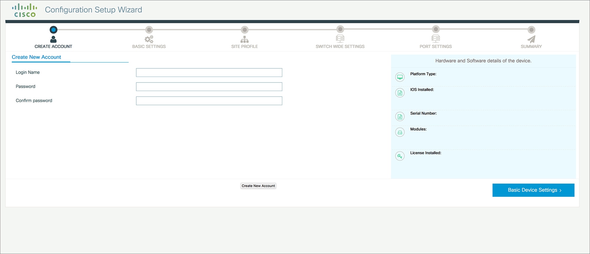
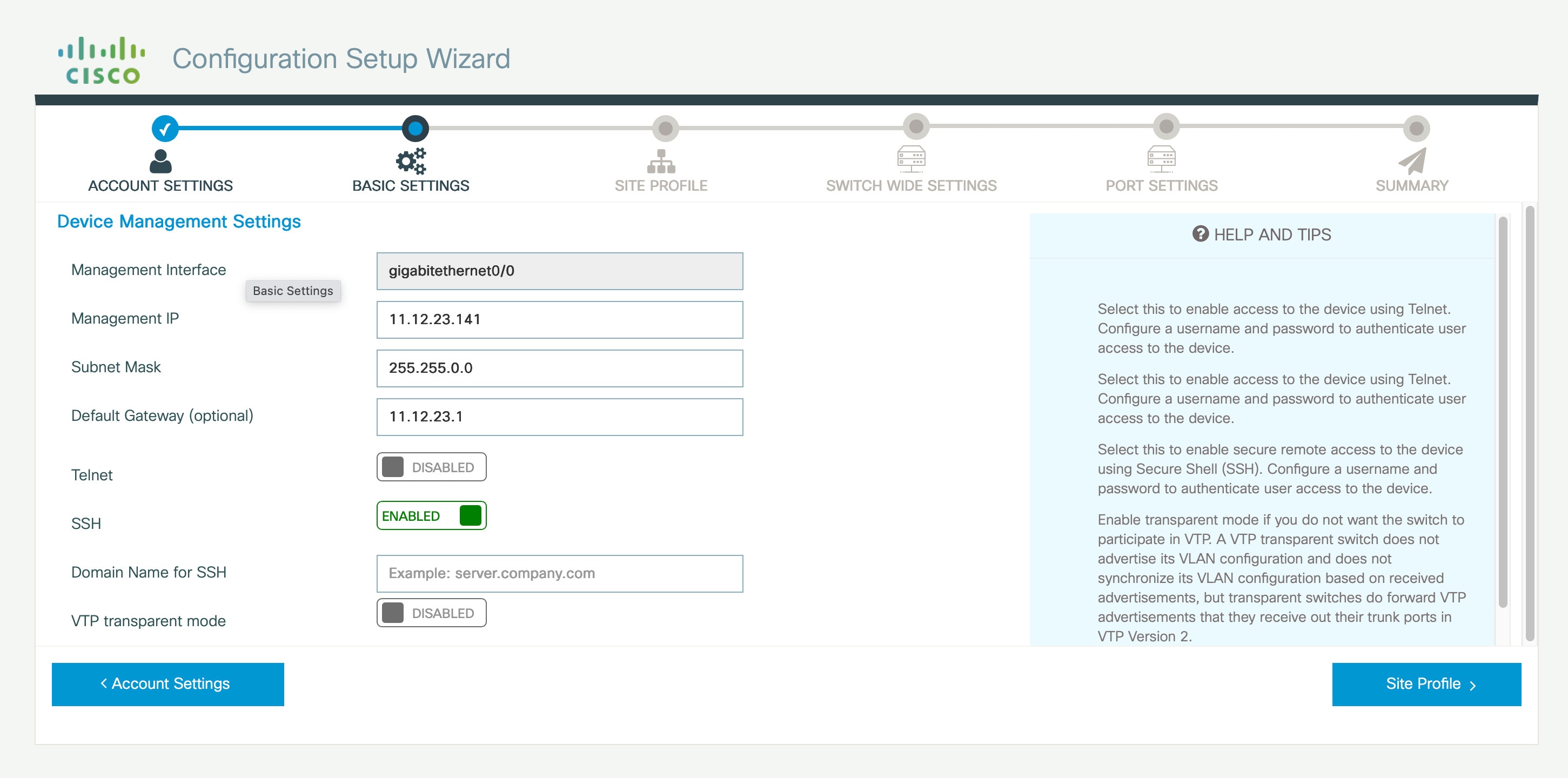
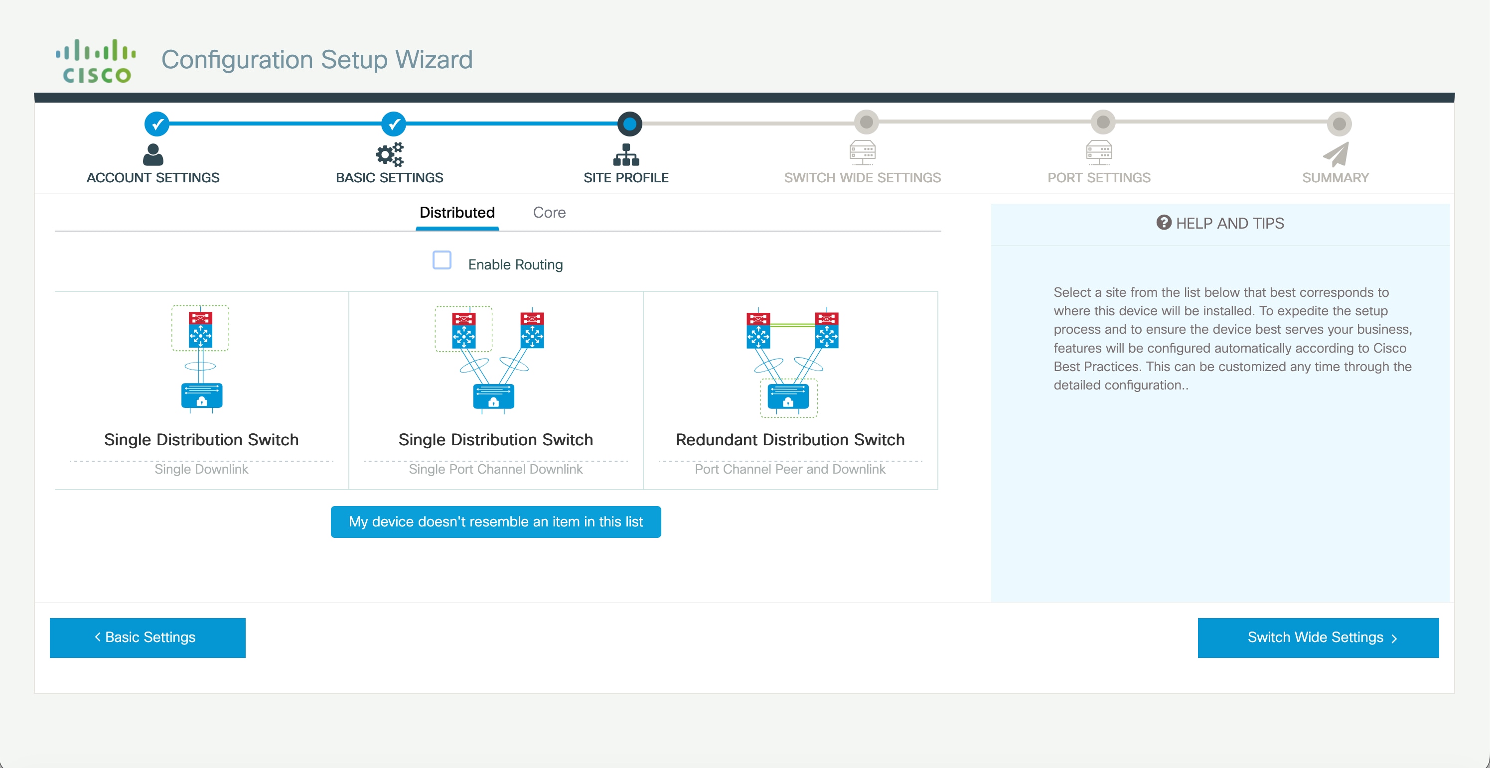
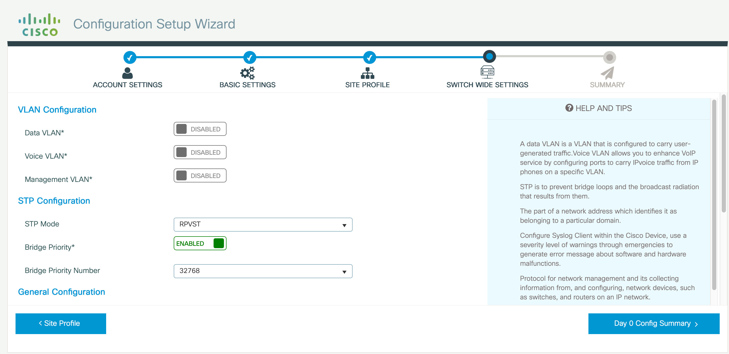
Web UI: Web User Interface feature support has been introduced. |
Cisco C9550 Series Smart Switches |
|
Cisco IOS XE 17.18.1 |
Web UI: Web UI feature is an embedded GUI-based tool for streamlined device provisioning, deployment, and management. |
Cisco C9350 Series Smart Switches Cisco C9610 Series Smart Switches |


 Feedback