Overview
The Cisco Nexus 9364C-GX switch (N9K-C9364C-GX) is a 2-rack unit (RU), fixed-port switch designed for deployment in data centers.
This switch has these ports:
-
64 100-Gigabit QSFP28 ports
-
Two management ports (one RJ-45 port and one SFP port)
-
One console port
-
1 USB port
 Note |
For ports 1 through 64, every 4 ports (1-4, 5-8, 9-12, and so on, referred to as a "quad") operates at a fixed speed. That is, all 4 ports will operate in 10G, or 40G, or 100G. This switch does not support mixed speeds in quad form. Auto-negotiation is not supported with 10G speed on Ports 1 through 64. |
This switch includes these user-replaceable components:
-
Fan modules (four—three for operations and one for redundancy [n+1]) with these airflow choices:
-
Port-side exhaust fan module with blue coloring (NXA-FAN-160CFM2-PE)
-
Port-side intake fan module with burgundy coloring (NXA-FAN-160CFM2-PI)
-
-
Power supply modules (two—one for operations and one for redundancy [1+1]) with these choices:
-
2000-W port-side exhaust AC power supply with blue coloring (NXA-PAC-2KW-PE)
-
2000-W port-side intake AC power supply with burgundy coloring (NXA-PAC-2KW-PI)
-
2000-W port-side exhaust DC power supply with blue coloring (NXA-PDC-2KW-PE)
-
2000-W port-side intake DC power supply with burgundy coloring (NXA-PDC-2KW-PI)
Note
Power supplies are the same type. Do not mix AC, DC, or HVAC/HVDC power supplies.
Note
All fan modules and power supplies must use the same airflow direction.
-
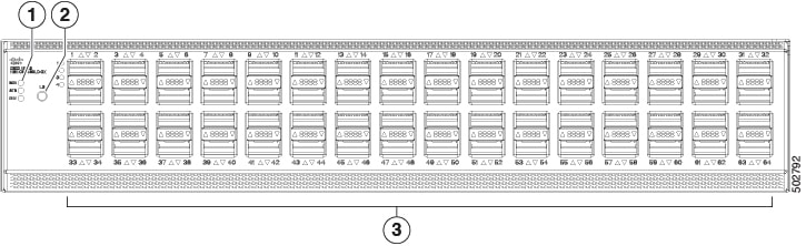
The figure shows the switch features on the port side of the chassis.
|
1 |
Beacon (BCN), Status (STS), and Environment (ENV) LEDs |
3 |
64 100-Gigabit QSFP28 ports |
|
2 |
Lane select button |
To determine which transceivers, adapters, and cables support this switch, see the Cisco Transceiver Modules Compatibility Information document.
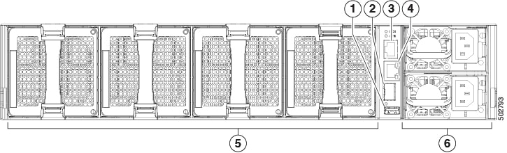
The figure shows the switch features on the power supply side of the chassis.
|
1 |
USB port (1) |
4 |
Management port (1—SFP optical port) |
|
2 |
Console port (1) |
5 |
Fan modules (4) with slots numbered from 1 (left) to 4 (right) |
|
3 |
Management port (1—RJ-45 copper port) |
6 |
Power supply modules (1 or 2) (AC power supplies shown) with slots numbered 1 (top) and 2 (bottom) |
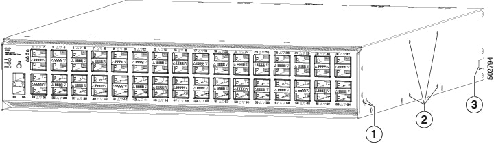
The figure shows the side of the chassis.
|
1 |
Screw holes for front mounting brackets (4-post rack installations) |
3 |
Notch on both sides of the chassis for locking the power supply end of the chassis to the bottom support rails (4-post rack installations). |
|
2 |
Screw holes for center-mount bracket (2-post rack installations) |
Note |
The access panel for DIMM upgrade is located on the underside of the chassis and uses Philips flat-head screws, M3 x 0.5 x 4 mm L, CSwZNwPAT,121'. |
Depending on whether you plan to position the ports in a hot or cold aisle, order the fan and power supply modules with port-side intake or port-side exhaust airflow. For port-side intake airflow, the fan and AC power supply modules have burgundy coloring. For port-side exhaust airflow, the fan and AC power supplies have blue coloring.
The fan and power supply modules are field replaceable. Replace one fan module or one power supply module during operations, as long as the other modules are installed and operating. If you have only one power supply installed, install the replacement power supply in the open slot before removing the original power supply.
Note |
All fan and power supply modules must have the same direction of airflow. Otherwise, the switch can overheat and shut down. |
 Caution |
If the switch has port-side intake airflow (burgundy coloring for fan modules), locate the ports in the cold aisle. If the switch has port-side exhaust airflow (blue coloring for fan modules), locate the ports in the hot aisle. If you locate the air intake in a hot aisle, the switch can overheat and shut down. |
 Feedback