Overview
The Cisco Nexus 9364C-H1 switch (N9K-C9364C-H1) is a 2-rack unit (RU), fixed-port switch designed for spine-leaf-APIC deployment in data centers.
The software on this switch has 6.4T traffic-processing capability.
The switch has these ports:
-
64 100-Gigabit QSFP ports
-
Two management ports (one RJ-45 port and one SFP port)
-
One Console port
-
One USB port
 Note |
For ports 1 through 64, every 4 ports (1-4, 5-8, 9-12, and so on, referred to as a "quad"). This switch supports mixed speeds in quad form. That is, all 4 ports can operate in a mix of 10G, 40G, or 100G. |
Port Considerations
These are the port considerations:
-
For this switch, a "quad" is defined as four ports in a column, beginning in the top left row and moving straight down to the bottom row, in that same column. Four ports = 1 quad.
-
10G QSA + 40G+100G can be mixed in a quad.
-
Access Breakout 4X10 and 4X25 are supported only on the first port of every quad (1,5,9,13....).
-
With breakout on the first port, the other 3 ports in a quad are hardware-disabled.
-
Ports 1/49-64 are default fabric uplinks and can be used for fabric discovery during initial bring up. Ports 1/49–62 support conversion to downlinks through port profiles.
-
Ports 1/63 – 64 are default fabric links used for fabric discovery and cannot be converted to down-link ports.
Note
Breakout configuration is not supported on port-profile-converted downlink 1/61; this can cause other ports to enter a hardware-disabled state and disrupt fabric discovery.
-
The Media Access Control Security (MACsec) feature is supported only on the last 16 ports, or ports 49-64.
For breakout information, see the Cisco APIC Layer 3 Networking Configuration Guide.
Leaf/Spine role considerations
Here are the leaf/spine role considerations:
-
The default role of this switch is as a leaf switch.
-
To change the switch from the default role, do this: the node appears as a discovered device in the fabric inventory view, set the role of the switch (spine or leaf), and the switch automatically reboots to come up in the configured role.
-
If you connect a default spine (i.e., a dual-role switch that by default is a spine switch, such as Nexus 9316D-GX) directly to an APIC, the change of the role to leaf switch is performed automatically by APIC, as well as the reboot. After that, the node appears in “Nodes pending registration.”
-
Register the node.
Note |
From ACI release 6.1(2) and later, you can change the role of any undiscovered switch before the switch is discovered using this CLI command:
|
Note |
The For more information about using this CLI command, see the Cisco APIC Getting Started Guide, Release 6.1(x). |
Discovery considerations
Here are the discovery considerations:
-
Leaf discovery via APIC – Connect a fully-fit APIC to one of the default downlink ports (1-48).
-
Leaf discovery via spine – Connect a discovered spine to one of the default fabric links (49-64).
-
Spine discovery via leaf – Connect a discovered leaf to one of the default fabric links (49-64) then convert the switch to spine (reboot is required).
-
Sub leaf discovery via leaf – Connect a discovered leaf to one of the default fabric links (49-64).
-
Multi-Pod first spine discovery via IPN – Connect the IPN to one of the default fabric links (49-64). Ensure the spine has at least one leaf node connected to it.
This switch includes these user-replaceable components:
-
Fan modules (four—three for operations and one for redundancy [n+1]) with these airflow choices:
-
Port-side exhaust fan module with blue coloring (NXAS-FAN-160CFM2-PE)
-
Port-side intake fan module with burgundy coloring (NXAS-FAN-160CFM2-PI)
Note
Table 1. Fan Speeds for this Switch Port-Side Intake
Fan Speed %
Port-Side Exhaust
Fan Speed %
Typical/Minimum
45%
45%
Maximum
80%
80%
Note
-
When more than one fan module (two rotors) fails, a major alarm is raised and a graceful shut down is performed within two minutes, unless the fan module is restored.
-
The switch functions normally when only one fan tray fails. If more than one fan tray fails, the switch issues a warning and powers down within two minutes.
-
-
-
Power supply modules (two—one for operations and one for redundancy [1+1]) with these choices:
-
1400-W port-side exhaust AC power supply with blue coloring (NXA-PAC-1400W-PE)
-
1400-W port-side intake AC power supply with burgundy coloring (NXA-PAC-1400W-PI)
-
2000-W- HVAC/HVDC DC airflow power intake with burgundy coloring (NXA-PHV-2KW-PI)
-
2000-W port-side exhaust DC power supply with blue coloring (NXA-PDC-2KW-PE)
-
2000-W port-side intake DC power supply with burgundy coloring (NXA-PDC-2KW-PI)
-
Note |
|
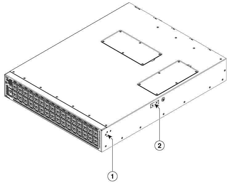
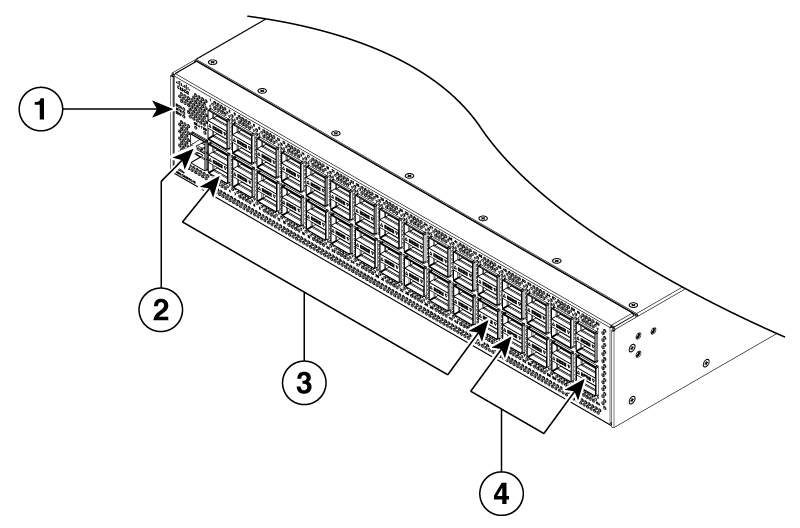
The figure shows the switch features on the port side of the chassis.
|
1 |
Screw holes for front mounting brackets (both left and right sides) |
2 |
Grounding pad |
|
1 |
Beacon (BCN), Status (STS), and Environment (ENV) LEDs |
3 |
40-/100-Gigabit QSFP28 ports (ports 1 to 48 in 4 rows of 12 ports) |
|
2 |
1-/10-Gigabit SFP+ ports (2) |
4 |
Green colored 100-Gigabit QSFP28 ports supporting MACsec (when software support is available) (ports 49 to 64 in 4 rows of 4 ports) |
Note |
To secure QSFP-100G-SR1.2, QSFP-100G-SM-SR and QSFP-40/100-SRBD functionality and reliability, this switch can only support those type of optics on 1/3/4 row at max ambient 35°C for PSE airflow. For PSI airflow, there is no impact. |
To determine which transceivers, adapters, and cables support this switch, see the Cisco Transceiver Modules Compatibility Information document.
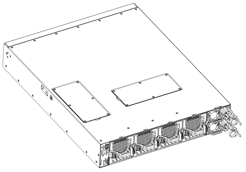
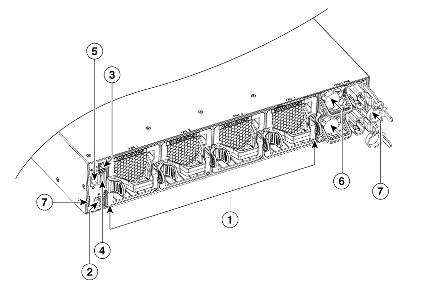
The figure shows the switch features on the power supply side of the chassis.
|
1 |
Fan modules (4) with slots numbered from 1 (left) to 4 (right) |
5 |
Console port (1) |
|
2 |
Management port (1—RJ-45 copper port) |
6 |
Power supply modules (1 or 2) (AC power supplies shown) with slots numbered 1 (top) and 2 (bottom) |
|
3 |
Management port (1—SFP optical port) |
7 |
Notch on both sides of the chassis at the end for rack mount supporting. |
|
4 |
USB port (1) |
Note |
The access panel for DIMM upgrade is located on the top side of the chassis and uses Phillips flat-head screws, M3 x 0.5 x 4 mm L, CSwZNwPAT,121'. |
Depending on whether you plan to position the ports in a hot or cold aisle, you can order the fan and power supply modules with port-side intake or port-side exhaust airflow. For port-side intake airflow, the fan and AC power supply modules have burgundy coloring. For port-side exhaust airflow, the fan and AC power supplies have blue coloring.
The fan and power supply modules are field replaceable. You can replace one fan module or one power supply module during operations, as long as the other modules are installed and operating. If you have only one power supply installed, install the replacement power supply in the open slot before removing the original power supply.
Note |
All fan and power supply modules must have the same direction of airflow. Otherwise, the switch can overheat and shut down. |
 Caution |
If the switch has port-side intake airflow (burgundy coloring for fan modules), locate the ports in the cold aisle. If the switch has port-side exhaust airflow (blue coloring for fan modules), locate the ports in the hot aisle. If you locate the air intake in a hot aisle, the switch can overheat and shut down. |
 Feedback