Connected Pipeline Overview
Executive Summary
This chapter provides a high level overview of the end-to-end Oil and Gas value chain and where pipeline solutions fit into this chain. It also provides an overview of the emergence of virtualization technologies into these environments. This document is written for an industry with a number of key trends:
- Health and Safety—The health and safety of employees continues to be of major importance for organizations. The industry looks to improve overall worker safety while specifically providing a safe working environment for remote or unaccompanied workers.
- Environmental Safety and Compliance—Solutions must meet or exceed industry standards or regulations such as the Pipeline and Hazardous Materials Safety Administration (PHMSA), with increased attention to safety and compliance in regulations a major design factor for telemetry and SCADA systems today.
- An Aging Workforce—Worker age and skill sets have changed. As younger workers with more of an IT-based skill set join the workforce, being able to train and provide remote expertise and consultation to new workers is essential.
- Predictive Automation and Process—Through Big Data, fog or edge compute, and analytics and cloud-based services, sensors are able to provide real-time information on such measures as temperature, vibration, pressure, flow, and current. Combining this with statistical models provides predictive methods for maintenance of equipment and streamlining of processes. The Internet of Things (IoT) has focused on connecting the unconnected through wireless and wired networks, and previously inaccessible data is now available for use.
- Security—As technology evolves, more devices are connected to the network, attackers use increasingly sophisticated methods, and OT and IT technologies begin to converge, protecting assets, people, and intellectual property from cyber and physical threats becomes ever more important.
It is essential to understand that a single technology cannot enable the industry to meet these requirements. Only a properly architected, secure integration of a number of technologies and applications will keep workers safe, improve efficiencies, reduce cost, and continue to drive innovation.
The Oil and Gas Value Chain
At a high level, the Oil and Gas value chain starts with discovering resources through exploration, and then the development, production, processing, transportation/storage, refining, and marketing/retail of hydrocarbons. This value chain is normally grouped into the upstream, midstream, and downstream areas, as shown in Figure 1-1.
Figure 1-1 Oil and Gas Value Chain
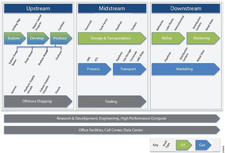
- Upstream—Upstream includes the initial exploration, evaluation and appraisal, development, and production of sites. This is referred to as Exploration and Production (E&P). These activities take place onshore and in the ocean. Upstream focuses on finding wells, determining how best and how deeply to drill, and determining how to construct and operate wells to achieve the best return on investment.
- Midstream—Midstream primarily focuses on the transport and storage of hydrocarbons via transmission pipelines, tankers, tank farms, and terminals, providing links between production and processing facilities, and processing and the end customer. Crude oil is transported downstream to the refinery for processing into the final product.
Midstream also includes the processing of natural gas. Although some of the needed processing occurs as field processing near the source, the complete processing of gas takes place at a processing plant or facility, reaching there typically from the gathering pipeline network. For the wholesale markets, natural gas must first be purified by removal of Natural Gas Liquids (NGLs) such as butane, propane, ethane, and pentanes, before being transported via pipeline, or turned into Liquid Natural Gas (LNG) and shipped. The gas can be used real-time or stored. The NGLs will be leveraged downstream for petrochemical or liquid fuels, or turned into final products at the refinery.
- Downstream—Downstream is concerned with the final processing and delivery of product to wholesale, retail, or direct industrial customers. The refinery treats crude oil and NGL and then converts them into consumer and industrial products through separation, conversion, and purification. Modern refinery and petrochemical technology can transform crude materials into thousands of useful products including gasoline, kerosene, diesel, lubricants, coke, and asphalt. Downstream also includes gas distribution pipeline networks.
A visual overview of the value chain is shown in Figure 1-2.
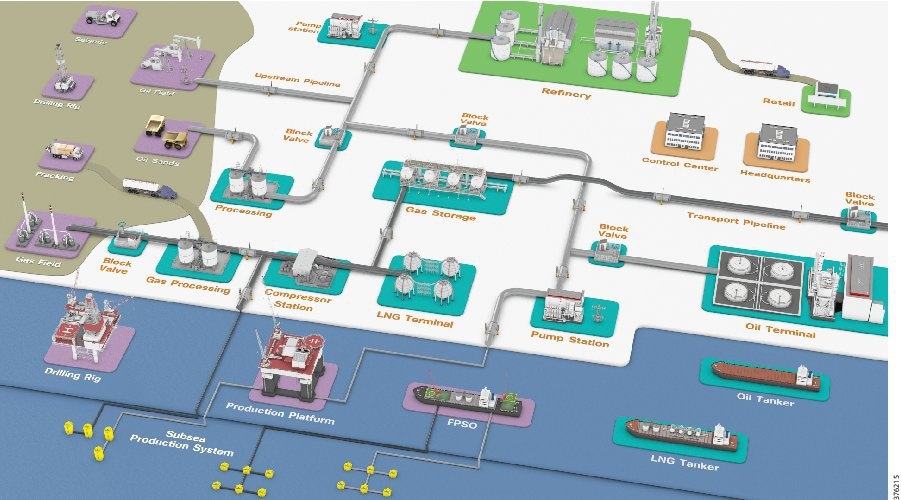
Transmission pipelines are the key transport mechanism for the oil and gas industry and operate continuously outside of scheduled maintenance windows. Pipelines provide an efficient, safe, and cost-effective way to transport processed or unprocessed oil, gas, and raw materials and products both on- and offshore. It is essential that they operate as safely and efficiently as possible, and, where problems occur, they must be able to rapidly restore normal operation to meet environmental, safety, and quality requirements.
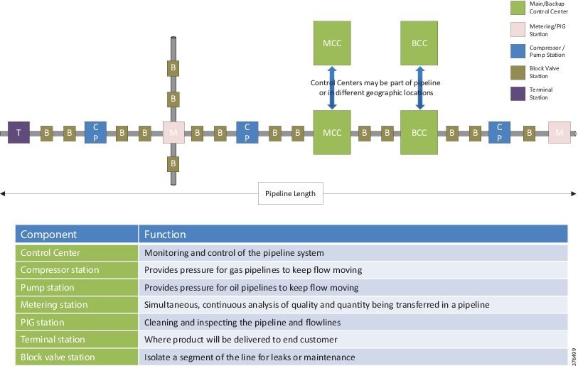
Oil and Gas pipelines (Figure 1-3) comprise operating process, safety, and energy management functions geographically spread along the pipeline for a set of stations. Stations vary in size and function, but typically include large compressor or pump stations, mid-size metering stations, Pipeline Inspection Gauge (PIG) terminal stations, and smaller block valve stations. Each process and application must be linked with the applications and processes at other stations, and at the Control Centers (main and backup) through an operational field telecoms infrastructure. The process must be done in a reliable and efficient way, avoiding communications outages and data losses. The Control Centers should also be securely connected to the enterprise through a Wide Area Network (WAN) to allow users to improve operational processes, streamline business planning, and optimize energy consumption.
Figure 1-3 Example Pipeline Station Distribution
Oil and Gas pipeline management is challenging, with pipelines often running over large geographical distances, through harsh environments, and with limited communications and power infrastructure available. In addition, pipelines must comply with stringent environmental regulations and operate as safely as possible, and address growing cyber and physical security threats.
Key pipeline requirements, however, have not changed. Pipeline integrity, safety, security, and reliability are essential elements that help operators meet demanding delivery schedules and optimize operational costs.
At the same time, new operational and multi-service applications are enhancing the way assets and personnel operate. Modern cathodic detection, distributed acoustic leak detection, landslip/earthquake detection, intrusion detection, and physical security applications allow operators to reduce downtime, optimize production, and decrease energy and maintenance costs. Real-time operational data access allows incidents to be identified and addressed quickly, or prevented from occurring in the first place.
Challenges must be addressed through a secure communications strategy to ensure operators can confidently rely on remote data, video, and collaboration solutions for safety and security in addition to operations.
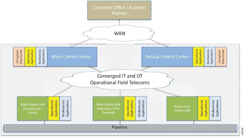
Communications architectures, technologies, solutions, and management for process, energy, security, and multi-service applications (Figure 1-4) must be robust, flexible, and scalable. They should be based on open standards, allowing operations from field device to Control Center, and Control Center to enterprise by combining real-time process and business control automation, information management, energy management, and security with global supervision.
Figure 1-4 High Level Pipeline Architecture
Pipeline Management Systems
Real-time monitoring and control through sharing and collection of data to a centralized PMS is critical for ensuring that the product is transported safely and efficiently. A PMS combines operational SCADA with real-time applications specific to the oil and gas industry, host-based leak detection, and historical flow measurement.
A well-designed PMS uses a hardware and software architecture that allows functions to be mobile, scalable, flexible, and robust. It also permits distribution of processing among different SCADA system components to optimize overall performance of the PMS.
These integrated applications provide pipeline operators:
- Real-time/near real-time control and supervision of operations along the pipeline through a SCADA system based in one or more Control Centers
- Accurate measurement of flow, volume, and levels to ensure correct product accounting
- Ability to detect and locate pipeline leakage, including time, volumes, and location distances
- Integrated security systems for personnel, the environment, and infrastructure using video surveillance, access control, and Intrusion Detection Systems (IDS)
- Ensured safe operations through instrumentation and safety systems
- Energy management system to visualize, manage, and optimize energy consumption within the main stations
SCADA System Design Principles
Pipeline requirements will vary depending on customer preference and project, so it is essential that any communications solution be scalable and modular; elements must be able to be interchanged without affecting fundamental architectural and operational functions.
The Control Center consists of operational and non-operational domains (Figure 1-5), which are divided into secure zones based on IEC 62443-3-3, Functional Requirement (FR) 5, Restricted data flow. This segments the control system architecturally via zones and conduits to limit the unnecessary flow of data.
Figure 1-5 Control Center Segmentation Domains
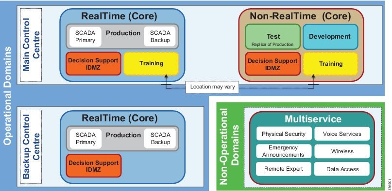
SCADA system environments within an architecture include operational zones for:
- Production—Domain controllers, real-time, historical and leak detection servers, operator workstations
- Test—Non-production replica of the operational SCADA system, allowing software and system changes to be validated prior to production without disrupting production
- Development—Development area for reports, displays and database changes
- Training—Training area built upon the environment that a pipeline controller lives in every day, via a fully functional SCADA control system together with accurate simulation of the pipelines they control
- Decision Support/Industrial DMZ (L3.5):
–![]() Decision support domain controllers and real-time historical and remote access services
Decision support domain controllers and real-time historical and remote access services
–![]() Isolates the operational system from any external systems or users
Isolates the operational system from any external systems or users
–![]() Synchronized with real-time and historical data from the Production system to provide a secure method of providing real-time data to external users
Synchronized with real-time and historical data from the Production system to provide a secure method of providing real-time data to external users
- With firewalls creating a DMZ, secure services are enabled to provide the external environments exposure to the data.
- Functions may include secure File Transfer Protocol (FTP) connections and long term historians
- Multi-service—Non-production applications which support the operation of the pipeline such as physical security, voice, Public Address and General Alarm (PAGA) safety announcements, video, and wireless
These building blocks are core components of a SCADA architecture design that can be deployed in one or more Control Centers. Customer philosophy and individual requirements will dictate how these zones are created and into which sites they are deployed. These are typically based on an internal risk assessment to ensure safe and reliable operations. Risk assessment guidelines to help determine philosophy and architectural design are available in the IEC 62443-3-2 standard Security for Industrial Automation and Control Systems - Security Risk Assessment and System Design.
To allow appropriate data flows to take place between zones for system operation, a communications and security infrastructure is implemented (see Figure 1-6), which provides conduits to transport only permitted data.
Figure 1-6 Control Center Communication Building Blocks

This network segmentation defined in IEC 62443-3-3, System Requirement (SR) 5.1, Network Segmentation, focuses on separating control system networks from non-control system networks, and also critical control systems from non-critical control systems. Options exist for logical segmentation, physical segmentation, or both. Again, the choice is based on customer philosophy. Guidance is available for the risk assessment to determine the philosophy in IEC 62433-3-2.
In addition to segmentation, boundary control needs to be established between each of these areas. Guidance on boundary control is found in IEC 62443-3-3, SL 5.2.
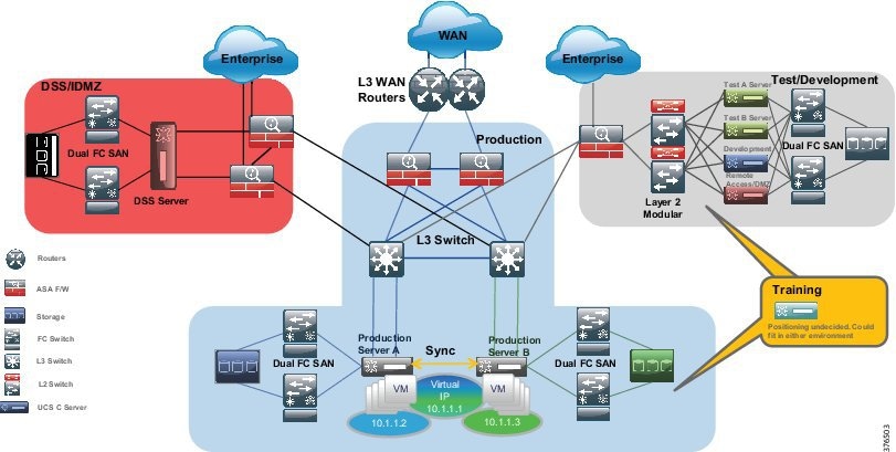
To ensure the required high availability and security, the SCADA PMS has traditionally been deployed on physically separate stacks (compute, storage, and network) with boundaries at the firewall level (see Figure 1-7). This ensures strict policy enforcement between zones, and leverages logical segmentation inside zones to differentiate between traffic types.
Figure 1-7 SCADA Deployment Physical Separation
Virtualization has transformed the data center environment over the past decade, allowing consolidation of multiple standalone bare-metal servers and applications onto smaller and more powerful nodes. The primary business push for virtualization was the aim to achieve better server usage from powerful and smaller physical servers, thus leading to an improved Total Cost of Ownership (TCO) and additional operational efficiencies (such as power, cooling, and space).
The deployment of full or partial virtualized solutions has increased in recent years, and industrial security standards and guidelines such as IEC 62443, NERC-CIP, IEC 62351, and the NIST Cybersecurity Framework have an increasing focus on the deployment of virtualization technologies.
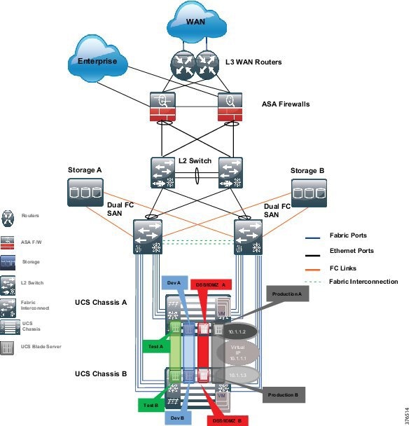
This means that the core SCADA Control Center architectural building blocks are implemented, with areas of shared infrastructure as shown in Figure 1-8.
Figure 1-8 SCADA Deployment Leveraging the Consolidated Architecture
The choice of deployment depends on end user requirements and philosophy. However, any deployment must focus on high availability, redundancy, and security. A holistic security strategy should include risk assessment, change management, recovery processes, training, information protection, and incident response—these will determine choice.
For the purposes of this CVD, the consolidated deployment will be used. This will allow the core architectural principles to be leveraged, and provides best practice design guidance and validation, including virtualization. This also ensures that high availability, reliability, and security requirements are met as per the following design guidance sections.
Security concepts and enforcement are drawn directly from IEC 62443 to support high availability and reliability. When any potential impacts may occur (such as scope for misconfiguration), they will be highlighted in the document.
The jointly architected and validated approach to pipeline management and telecommunications offers many realizable benefits. Solution integration quality and interoperability are maximized, while design and testing time are minimized. End users have a single point of reference accountable for integration and operational success from hardware, software, security, and management perspectives throughout a project life cycle. The jointly architected design will provide maximum benefit for current operations, and be a platform for future application enablement and integration.
The key elements of this jointly architected and validated design will be discussed in detail in the following sections.
Availability
The system design must encompass a highly available architecture. The pipeline operator must have control of the pipeline 24 hours a day and 365 days of the year. Any loss of visibility or communications will either enforce a shutdown of the process resulting in loss of revenue, or in a worst case scenario, not provide the ability to shut down the pipeline under a catastrophic safety incident such as a major leak.
No Single Point of Failure (SPOF) should occur on any critical system component of the SCADA system design. A critical component is any component whose failure directly and adversely affects the overall performance of the SCADA system or its ability to continue performing the critical SCADA functions of monitoring and control. The SCADA system uses modular components so that the failure of a single component does not render other components inoperative.
Within this design, redundancy is provided for all critical SCADA functions for monitoring and control. Components comprising the standby capability continuously receive updated data, as appropriate, to provide a hot-standby capability in case of a hardware- or software-initiated failover. As an example, a hot server or critical SCADA application will have a standby equivalent within a Control Center and updates will be passed from this server/application to a backup Control Center if deployed.
The SCADA system connects to the telecommunication networks in such a way that a failure of these networks does not affect the ability of the SCADA system to perform its critical functions for monitoring and control. The logic within controllers and the safety systems along the pipeline will still operate if the Control Center loses connectivity to the pipeline stations; however, the ability to control and monitor the pipeline would be lost. Therefore, it is critical that communications to a Control Center are maintained.
Security
Security, safety, and availability are tightly aligned within an industrial security framework. When discussing industrial network security, customers are concerned with how to keep the environment safe and operational.
Historically, industrial control systems were seen as isolated from the outside world and utilized proprietary technologies and communications. Security was seen as more of a security-by-obscurity approach. Security outside of physical security wasn't a primary concern. With the modernization of control systems moving towards Consumer-Off-the-Shelf (COTS) products leveraging standardized protocols and connecting to public networks, the process domain now, more than ever, depends on a security framework and architecture. By using more IT-centric products and technologies, and providing connectivity to the enterprise and outside world, new cyber-attacks from both inside and outside the operational environment can potentially occur.
Security incidents can be categorized as either malicious or accidental:
- Malicious acts are deliberate attempts to impact a service or cause malfunction or harm. An example is a disgruntled employee planning to intentionally affect a process by loading a virus onto a server used within the operational control domain or taking control of a process by spoofing a Human Machine Interface (HMI).
- Accidental incidents are probably more prevalent in these environments. Someone may accidentally incorrectly configure a command on a piece of networking equipment, or connect a network cable to an incorrect port. These may be accidental, such as human error, but could be malicious as well while compromising the safety of people, processes, and the environment.
It is recommended to follow an architectural approach to securing the control system and process domain. Recommended models would be the Purdue Model of Control Hierarchy, International Society of Automation 95 (ISA95) and ISA99/IEC 62443. To help adhere to the requirements of IEC 62443 and achieve a robust solution for security and compliance, it is essential to use an end-to-end approach with technologies designed to operate together, while minimizing risk and operational complexities, as shown in Figure 1-9.
Figure 1-9 IEC Foundational Requirements
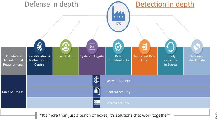
Figure 1-9 highlights the seven Foundational Requirements (FRs) defined in the ISA-62443 series of documentation:
- Identification, Authentication & Control (IAC) (ISA-62443-3-3 FR 1)—Identify and authenticate all users (humans, software processes and devices) before allowing them to access to the control system.
- Use Control (UC) (ISA-62443-3-3 FR 2)—Enforce the assigned privileges of an authenticated user to perform the requested action on the IACS and monitor the use of these privileges.
- System Integrity (SI) (ISA-62443-3-3 FR 3)—Ensure the integrity of the IACS to prevent unauthorized manipulation.
- Data Confidentiality (DC) (ISA-62443-3-3 FR 4)—Ensure the confidentiality of information on communication channels and in data repositories to prevent unauthorized disclosure.
- Restricted Data Flow (RDF) (ISA-62443-3-3 FR 5)—Segment the control system via zones and conduits to limit the unnecessary flow of the data
- Timely Response to Events (TRE) (ISA-62443-3-3 FR 6)—Respond to security violations by notifying the proper authority, reporting needed evidence of the violation and taking timely corrective action when incidents are discovered.
- Resource Availability (RA) (ISA-62443-3-3 FR 7)—Ensure the availability of the control system against the degradation or denial of essential services.
Defense in Depth is a common term that denotes the multiple layers required to incorporate a security framework. Security isn't just about the technologies to prevent incidents, but also incorporates people, processes, training, and continual assessment. In addition to Defense in Depth, it is also essential to Detect in Depth to ensure malicious activity can be discovered by more than one medium.
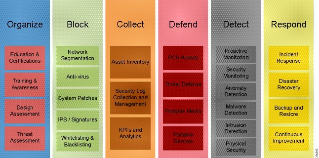
Security is not a one-off incident and response; it must be treated in a life cycle manner. This involves everything from awareness through to response. Figure 1-10 highlights the security life cycle approach in the Cisco Risk Control Framework. These concepts are built into the proposed architecture.
Figure 1-10 Cisco Risk Control Framework
Management
Management and diagnostics involves tools, applications, and devices used to monitor and maintain the Control Center architecture. Although a typical pipeline network does not drastically change after deployment, the network needs to be maintained and managed. Historically, these functions have not been incorporated into the automation and control systems, but this paradigm is changing because infrequent updates are more prevalent in today’s pipeline.
Business practices and levels of expertise may dictate the management practice and roles and responsibilities of the system. Companies are merging the boundaries between Information Technology (IT) and Operational Technology (OT) where these have historically remained separate domains. Staff may have differing levels of knowledge to support the applications and infrastructure of the Control Center environment. As an example, if more IT-aware personnel are maintaining the Control Center environment, they must be aware of the business requirements that dictate the security and availability aspects of the operating environment.
Pipeline architectures have differing availability requirements (24 hour per day continuous operations), Service Level Agreements (SLA), and processes compared to the typical enterprise domain. If personnel managing the system are more operationally focused, then it is important to understand the networking technologies and tools used to administer the system. It is therefore critical that staff training that is in conjunction with validated and documented processes is established so that any misconfiguration incidents are restricted.
The management systems follow the Fault, Configuration, Accounting, Performance and Security (FCAPS) model to help provide and maintain the availability and security of the Control Center architecture. FCAPS management all help to facilitate and monitor the health of the system.
- Fault Management—Detect, isolate, and notify administrators of any issues or faults within the Control Center to help aid with a timely fault resolution.
- Configuration Management—Configure, manage, and maintain the infrastructure and applications for the Control Center. This includes inventory management, software management (upgrades and patch management), configuration management (backups, archiving, and comparisons), and well documented, validated procedures to support change and replacement management.
- Accounting Management—Account management is usually defined for billed networks in order to provide accounting information. Within the context of this system, the A will stand for accounting as it relates to user access and permissions to provide Role-Based Access and Control (RBAC).
- Performance Management—Collect, analyze, and report the application and infrastructure performance of the Control Center and report on any thresholds that may be exceeded.
- Security Management—Manage, monitor, log, and control the security of the infrastructure to identify, defend, and prevent any security threats or breaches.
Although not explicitly defined in each of these areas, logging and audit trails need to be maintained to understand all aspects of FCAPS for the Pipeline Control Center.
Baseline Integrated SCADA System
The design guide and validation effort follows Schneider Electric's best practice deployment model for achieving a holistic integrated solution for the Control Center SCADA.
Baseline Integrated SCADA System (BLISS) combines Schneider Electric's Enterprise OASyS SCADA, and its advanced applications with Cisco compute and networking, to provide a fully integrated holistic PMS for the Control Center. BLISS offers a validated solution to provide fast, secure, and efficient deployment either as part of a pipeline Greenfield deployment or as an upgrade to an existing pipeline.
 Feedback