- Control Center Overview
- Schneider Electric Pipeline Management Solutions
- Production Environment
- Test and Development
- Decision Support System/Industrial Demilitarized Zone
- Control Center Availability and Security
- Multi-Service Traffic (Non-Operational Applications)
- Operational Communications Network Overview
- Use Case: SCADA Real-time /Near Real-time Operations
Connected Pipeline Architecture
This chapter includes the following major topic:
The Connected Pipeline System delivers a forward-looking, flexible, and modular architecture that enables customers to build the components into an existing system or for a Greenfield deployment. Throughout the architecture, high availability and security are key deliverables. The end-to-end infrastructure provides the following:
- High Availability—Redundancy and reliability mechanisms at the physical, data, and network layer, including robust differentiated QoS and device level redundancy
- Multi-Service Support—Operational and non-operational applications coexisting on a communications network, with mechanisms to ensure the right applications operate in the right way at the right time
- Multi-Level Security—Protect against both physical and cyber-attacks, and non-intentional security threats
- Integrated Management—Network, security, and administration management, from the instrumentation or sensor to the Control Center application
- Open Standards—Based on IP, with the ability to transparently integrate and transport traditional or older serial protocols, and ensure interoperability between current and future applications
The Operational Telecom Network (OTN) and pipeline station architecture are outside the scope of this document, although a high level description of the architecture is included. This document will prioritize the virtualization and operations of the OASyS DNA SCADA software and supporting applications into an operational Control Center architecture based on BLISS.
Figure 2-1 Cisco/Schneider Electric Connected Pipeline Reference Architecture
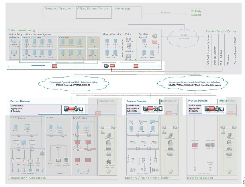
The architecture is based on a three-tier building block approach as defined in the joint Cisco Schneider Electric reference architecture (see Figure 2-1).
- Control Center—Virtualized, geographically separate, redundant Control Centers
- Operational Telecoms Network—End-to-end communication from field device to Control Center application, for operational and multi-service applications
- Pipeline Stations—Local area networks inside the stations for operational and multi-service applications
Control Center Overview
The SCADA system provides operators who are located in a control room the ability to monitor, operate, and control the operations along the pipeline. The SCADA system consists of multiple environments within the architecture.
Schneider Electric Pipeline Management Solutions
Schneider Electric's Enterprise Pipeline Management System (EPLMS) consists of multiple services and applications to facilitate safe and efficient operations, as shown in Figure 2-2:
Figure 2-2 Schneider Electrics Pipeline Management Systems
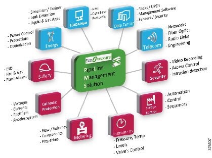
- RealTime SCADA—Schneider Electric's OASyS DNA transcends the traditional SCADA environment by incorporating the workflow needs of customers in real-time. OASyS DNA is an infrastructure product that adapts to the diverse and changing needs of an enterprise. From the field to the enterprise, OASyS DNA allows access to operational and historical data securely at anytime from anywhere.
- Oil and Gas Application Suite—Schneider Electric's RealTime Oil and Gas Suite works with the proven Schneider Electric OASyS DNA SCADA system to centralize delivery of key oil and gas pipeline information, enhancing a company's operational environment. Critical data is received for improving pipeline operations and meeting business goals. Schneider Electric offers up-to-the-minute metering and flow totaling; and calculates and monitors line pack, tank storage, hydraulic profiles, and compressor and pump performance in real-time.
- Leak Detection—The main strength of Schneider Electric's SimSuite Pipeline lies in its ability to accurately model the pipeline more completely than other available solutions. The leak-detection application uses a combination of methods to detect and locate leaks. Leaks can occur anywhere on the pipeline; they can vary in size; and they can be caused by fatigue, corrosion, equipment failure, or theft. Large and small leaks can be detected using multiple mass-balance calculations. Pressure-drop calculations can be used to locate the leak.
- Measurement Data—The Schneider Electric Measurement Advisor, empowered with Schneider Electric's advanced measurement user interface, provides the efficient and accurate means to configure devices and collect, validate, modify, and reconcile oil and gas measurement data. Part of the Schneider Electric suite of oil and gas solutions, Schneider Electric Measurement Advisor is the high-mileage solution that gathers measurements for multiple pipelines that interface with various Ethernet in the First Mile (EFM) polling engines, SCADA systems, chart integrators, third-parties, and manual input. Schneider Electric Measurement Advisor allows the precision required at every step to achieve process-wide accuracy.
Production Environment
The Production Environment enables real-time operations of the pipeline network. It consists of real-time servers, operator workstations, historical servers, support servers, leak detection servers, and any ancillary services such as domain controllers. The following is a brief description of the server and its function within the production environment:
- Real Time Servers—Real-Time Service shall provide the monitoring and control function for the SCADA system.
- Domain Controller—Dedicated for SCADA, areas of responsibility, and user roles
- Logging Server—OASyS Logs, data playback, and windows events
- Deployment Server—Display and database commissioning system
- Historical Servers—Provide long-term storage of Real-Time measurement, event, alarming and other relevant data monitored or generated by the SCADA system
- Operator Work Stations—Interface for operating, controlling, and monitoring the pipeline
- Leak Detection Server
Test and Development
Test System
Test systems are a non-production replica of the Production SCADA system. This provides an environment for the following functions:
Development System
The development system, which provides at least one development server per OASyS DNA system, has the following functions:
Decision Support System/Industrial Demilitarized Zone
The Decision Support System (DSS) isolates the operational system from any external systems or users. It is updated with real-time and historical data from the live system to provide a secure method of providing real-time data to external users. With firewalls creating an Industrial Demilitarized Zone (IDMZ), secure services are enabled to provide the external environments exposure to the data. The following describes the servers within the DSS and their functions:
The IDMZ will facilitate extra services to assist with the day-to-day operations in maintaining the integrity of the system. Such functions as patch management servers, secure FTP servers, and anti-virus servers will be housed within the IDMZ environment.
Control Center Availability and Security
This section describes control center availability and security.
Availability
Within a SCADA system design, it is recommended that no SPOF should exist. To provide the level of availability required, multiple layers of resiliency are built into the Control Center and communications architecture so that a failure of a single component does not disable the ability to control the pipeline. Redundancy is provided for all critical components and functions of the SCADA system. The Control Center will ensure availability of the IACS system against degradation or denial of essential services. High availability is recommended for the network, server, storage and application components. Depending on the risk assessment, customer philosophy, and cost of infrastructure, the chosen architecture may or may not adhere to all of the following guidelines recommended within a Control Center:
- Dual servers (physical or virtual) for all critical components
- Dual application instances in a hot/standby state machine configuration
- Dual networking platforms, including routers, switches, firewalls, and Fabric Interconnects
- Storage redundancy incorporating Redundant Array Of Independent Disks (RAID), controller, and chassis redundancy where appropriate
- Dual Storage Area Networks (SANs)
- Multiple data communication paths across the network
- Enhanced resiliency technologies provide fast failover from active to standby components
- Constant update of information between hot/standby application instances
- QoS to provide prioritization of key network traffic and data
- Process and procedures to guide quick replacement of failed devices in situations where redundancy may have not been provided
Because of the critical nature of supporting a pipeline infrastructure, at least one Backup Control Center is recommended, but situations may dictate more or less. This backup provides redundancy for events that may take down a primary Control Center. Communications may be lost with the remote pipeline or a natural disaster may occur that renders a Control Center unavailable to the pipeline stations. This Backup Control Center should be geographically separate from the Primary Control Center. The real-time and historical data stored on the components located at the backup system are kept synchronized with the primary system located in the Primary Control Center, at all times. In the event of a failure, the backup system is capable of running the entire operations for the pipeline.
Security
After availability, the integrity and confidentiality of the control system are the next most important. Integrity protects data and systems from intentional or accidental alteration. Confidentiality helps ensure that data cannot be accessed by unauthorized users. The following key security concepts, which are described in “Connected Pipeline System Design,” will help provide availability of the system and support the networking infrastructure:
- Data Confidentiality and Privacy. Ensure the confidentially of information on the communications network and in storage. This may include methods such as segmentation, protecting against unauthorized access, and encryption of the data.
- Provide Network Segmentation and Isolation Techniques using Zones and Conduits. Within the Control Center, isolate each of the environments into zones that share a common set of security requirements or functions. Security issues seen in one zone need to be restricted from affecting or cross-pollinating into other zones. The security zones can be segmented using physical separation such as specific devices and interfaces or logically such as with Virtual Local Area Networks (VLANs).
- Restricted communications between zones using Firewalls, Access Lists, and Intrusion Protection System (IPS) devices where available. VLANs restrict traffic within a Layer 2 networking instance and the Layer 3 gateway can be used to apply policy to allow or restrict traffic between security zones.
- Threat detection and mitigation using the Firewalls, IPS devices, and segmentation.
- Access control to restrict access to resources to which a user or device is not authorized.
- Manage, monitor, log, and control the security of the infrastructure to identify, defend, and prevent any security threats or breaches.
IDMZ/DSS to isolate the operational system from any external systems or users and provide authorized remote access to the process control domain from external sources.
Figure 2-3 highlights the zones and conduits seen within the BLISS Control Center architecture. Each of the colors depicts an environment, its zone, and conduit. Details of the specific implementation are described in Chapter3, “Connected Pipeline System Design”
Figure 2-3 BLISS Zones and Conduits

Multi-Service Traffic (Non-Operational Applications)
Multiple services will be deployed to support pipeline communications, physical security, and business enabling applications within the pipeline architecture. Segmentation of the multi-service applications from the operational communications is a common requirement. Regulatory demands, security concerns, and confidence of the operator to house the multi-service on the same infrastructure as the SCADA servers will drive the Control Center multi-service architecture. The two deployment models for enabling multiple services within the Control Center architectures for pipelines are as follows:
- The first will house the multiple services on a separate infrastructure from the SCADA environment, as depicted in Figure 2-4.
- The second will house the multiple services on the same physical infrastructure as the SCADA environment, as depicted in Figure 2-5.
Figure 2-4 Segmented Multi-Service from SCADA Option 1
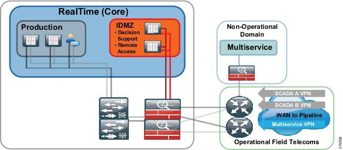
Figure 2-5 Segmented Multi-Service from SCADA Option 2
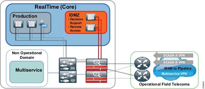
This version of the architecture will support Option 1 where multiple services will be passed to a totally separate infrastructure, outside of the operational environment.
Operational Communications Network Overview
The Operational Telecoms architecture provides a multi-service environment that encompasses operational services (such as SCADA and process applications) and non-operational services (such as CCTV and Voice) that enable business efficiency and security along the pipeline. See Figure 2-6.
Figure 2-6 End-to-End Communications Architecture Overview
Connectivity is required for communications between Control Centers, between the Control Centers and the pipeline, and for any inter-station communication along the pipeline. The key requirements of availability and security for the services, as mentioned in the Control Center overview are primary considerations for the architecture. Multiple secure paths through the network are provisioned to support this communication. Services are segmented, isolated, and prioritized so that SCADA networks and multi-service traffic will not affect each other under normal operations, security incidents, or network congestion.
The communications network can be built using various networking technologies. Factors that influence the communications architecture include power and space availability at the various sites, capital and operational costs, and the customer's preferred technology. Figure 2-7 provides an overview of the various technologies that may contribute to a pipeline communications architecture key requirements.
Figure 2-7 Pipeline Communications Architecture Technology Overview
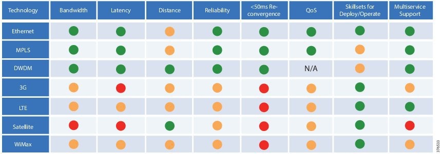
The colors in Figure 2-7 signify the following:
- Green—Meets the requirements shown in column headings
- Amber—Meets requirements, but limitations exist
- Red—Does not meet requirements
As detailed earlier, various types of stations will run along the pipeline. A pipeline segment will be bookended with larger stations such as a main terminal or a pumping/compressor station. In between these larger facilities intermediate stations, such as metering stations and block valve stations, will exist. Regardless of the roles, the stations still have very similar requirements, with environmental or physical factors affecting the architecture within a station. Power may be limited at some of the stations, especially those unmanned and in remote locations such as the block valves.
Services at the stations include:
- Process control for the transportation of oil along the pipeline
- Intelligent power and motor control to manage and control the energy supply at larger stations
- Voice over IP (VoIP) for traditional enterprise voice services and a PAGA system
- Video surveillance as a component of a perimeter security system
Figure 2-8 Compressor/Pump Station
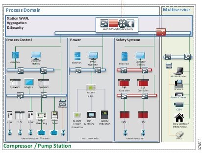
These services lend themselves to providing a multi-service and operational infrastructure within the station environment. Security and availability are key considerations again at the station level. Segmentation of services, as previously defined, will be built into the architecture. Security policies at the network edge will be implemented that protect against unauthorized access, which is particularly important where the stations are unmanned and prevent cross-pollination of traffic between security zones.
QoS classifications, markings, and policies will provide the prioritization of resources for the services at the station and for traffic traversing the operational network to other stations or for Control Center communication.
Use Case: SCADA Real-time /Near Real-time Operations
This section describes SCADA-to-Pipeline and Control Center-to-Control Center communications.
Figure 2-9 depicts SCADA real-time/near real-time operations.
Figure 2-9 SCADA Real-time/Near Real-time Operations
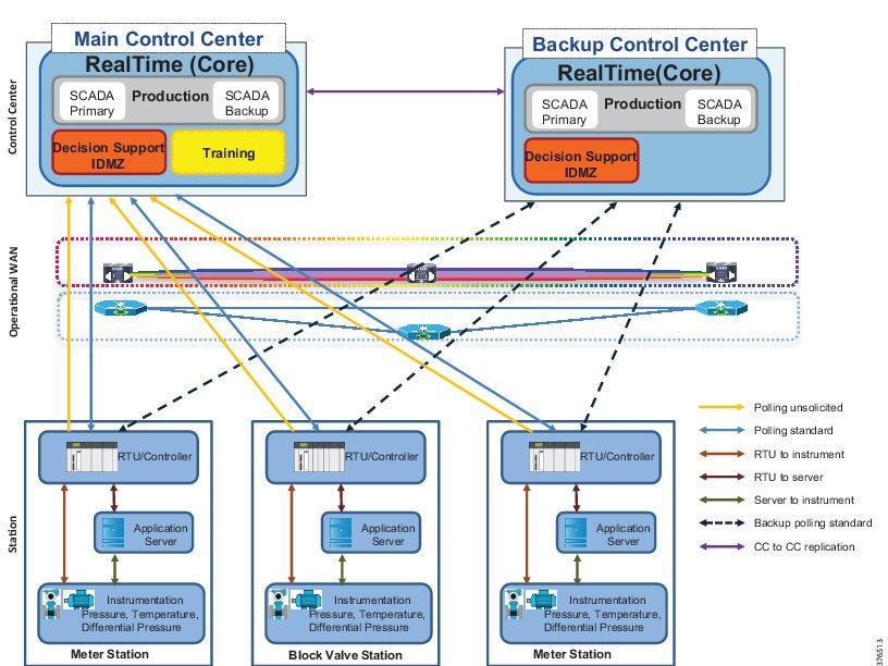
SCADA to Pipeline
Operators in the control room rely on consistent reliable data from the pipeline in real-time to make critical decisions for the transport of the product. The control system must be able to poll, collect, store, and display information from Intelligent Electronic Devices (IEDs), including Remote Terminal Units (RTUs), Programmable Logic Controllers (PLCs), substation controllers, and measurement instruments. Real-time communications between the pipeline and the control system must be available, reliable and secure.
The operational SCADA traffic is segmented from any other traffic that may be traversing the network and should be prioritized over non-operational less critical traffic. This segmentation must be carried through the architecture from the instrumentation reporting data within the pipeline stations into the Control Center. Prioritization within the SCADA system is also a requirement. In an application such as leak detection, information must be relayed to a decision point within the system as a priority above all other SCADA traffic.
Unsolicited traffic is sent at irregular intervals as events occurs from the RTU/Controllers to the Active Control Center. Solicited traffic is originated from the Control Center, either through an application or initiated by an operator.
Control Center-to-Control Center Communications
A backup Control Center provides disaster recovery within the system. The real-time and historical data stored on the components located in the backup system are kept synchronized with the primary system located in the primary Control Center at all times. Data is continuously updated and availability of communications is a priority. A variety of communication takes place between OASyS DNA Control Centers. For example, the OASyS RealTime Servers pass configuration information and real-time SCADA data. Control Centers will also have one or more domain controllers that need to communicate Active Directory information to each other.
The system provides secure available communications for these components between the Control Centers. Each OASyS DNA system within an installation must have a properly configured firewall or router acting as a boundary between the control network and any external LAN or WAN as per IEC 62443-3-3, Foundational Requirements, SR 5.2, Zone Boundary Protection. This configuration restricts communications to only those ports required for domain controller communications and OASyS DNA functionality. Firewall access controls must be configured to control traffic bi-directionally.
 Feedback