Connected Pipeline System Design
BLISS Design
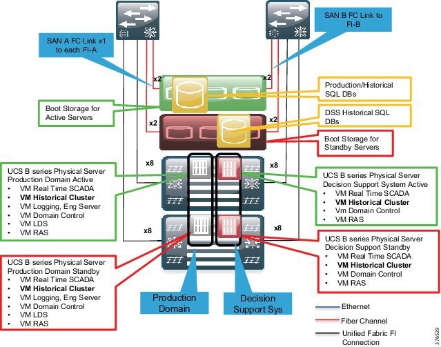
Figure 3-1 provides an overview of the SCADA system physical architecture. The BLISS system follows a single layer data center design. The Control Center is built around the Cisco Unified Compute System (UCS), Nexus 3524 Ethernet-collapsed Aggregation/Access Networking Platform, Cisco Adaptive Security Appliance (ASA), and the EMC VNX series storage arrays.
Figure 3-1 SCADA System Physical Architecture Overview
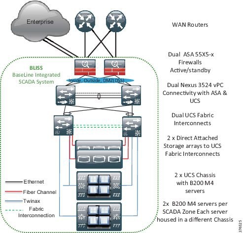
In the context of the Schneider Electric BLISS, the UCS B series servers will house each of the production, DSS, test, development, and training environments using virtualized servers. These services and applications will run on Microsoft Hyper-V virtual-enabled machines. Each physical server will house an environment dedicated to it with a backup version of the server housed on another physical server in another UCS chassis. Two storage arrays will support redundancy and will be directly connected to the UCS system at the 6248 Fabric Interconnects. A pair of Nexus 3524 switches will extend the Layer 2 domain to a pair of ASA firewalls where Layer 3 gateway functionality will enable policy management for any traffic that needs to traverse outside of the Layer 2 domain. The operator workstations will have connectivity into the environment through a pair of Catalyst switches that will have connectivity to the Nexus 3524 switches.
Functional Data Center Design
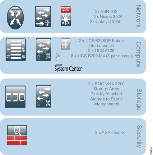
The Control Center design, as shown in Figure 3-2, can be broken into four key functional blocks:
- Network—LAN design, Layer 2 and Layer 3 Networking
- Compute—UCS B series, Hypervisor, vSwitch
- Storage—Fiber Channel, SANs (directly attached to Fabric Interconnects)
- Network Security—IDMZ, Decision Support System
Figure 3-2 Functional Data Center Design
Network
The Networking Layer connects to the WAN Provider Edge (PE) router terminating the L3VPN. The Nexus 3524 Layer 2 switch is serving as both an access and aggregation node. Although the ASA is stated to be a security device, it is also serving as a Layer 3 gateway within this architecture to enforce networking policy and provide termination of the Layer 2 domain. The 3850 switches will extend the networking architecture to provide network connectivity for the operator workstations.
Compute
The Compute Building block includes several systems. The Unified Compute System features redundant 6248 Fabric Interconnects, UCS 5108 blade chassis, and B series blade servers. The hypervisor in this architecture will be Microsoft Hyper-V. Within this architecture, the Hyper-V vSwitch provides a virtual access switching layer that is applied to the Virtual Machines on the physical servers that can apply QoS, Access Control Lists (ACLs), and enhanced security deeper into the architecture.
Storage
The storage layer includes the 6248 Fabric Interconnects for connectivity to the EMC storage. This is directly connected from the Fabric Interconnects to the storage using Fiber Channel. EMC is used here in this release; however, the solution is storage agnostic.
Security
Finally, the ASA firewalls have the capability to not only provide traditional firewall services such as stateful inspection, access control, and remote access, but with Sourcefire can also provide IPS, Intrusion Detection System (IDS), and anomaly detection. In this phase, IPS and IDS will not be enabled. Only traditional firewall services will be validated.
Security Design
This section describes security design, which includes segmentation design, compute segmentation, and storage segmentation.
Segmentation Design
In Oil and Gas Pipeline architectures, the ability to securely restrict and isolate services to preserve the integrity of the traffic is paramount. Intentional and accidental cross-pollination of traffic between untrusted entities must be restricted. Securing a perimeter for a SCADA service can be achieved using isolation techniques at the various levels of the infrastructure. The security zones can be segmented using physical separation, such as specific devices and interfaces, or logically, such as with VLANs. VLANs restrict traffic within a Layer 2 networking instance and an ASA firewall can be used to apply policy to allow or restrict traffic between security zones. With logical association of virtual firewalls, VLANs, and L3VPN instances, physically-separated interfaces of equipment and security policies, perimeters and zones can be defined. These techniques are not just restricted to traditional networking platforms, but also must be followed throughout the architecture into the compute and storage areas. These techniques may be physical or logical: physical in the segmentation of physical equipment or logical where comfort and familiarity with virtualized techniques exists or where it makes sense from a business perspective.
Control Center Segmentation and Zones
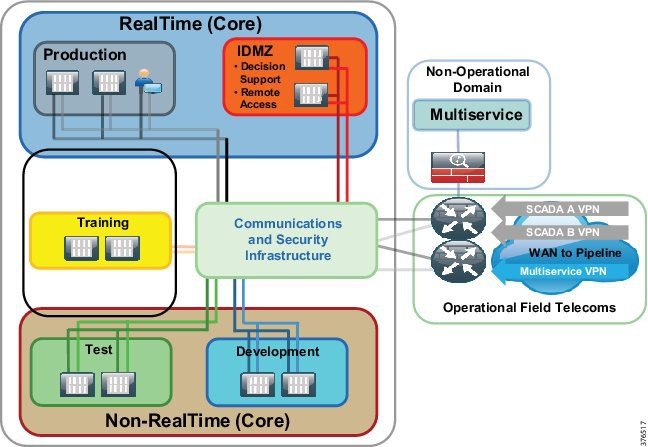
To address the requirement to segment services to promote a dedicated infrastructure per service, the Connected Pipeline 1.0 architecture will promote physical and logical path isolation techniques. The BLISS architecture will take ownership of the security and segmentation from the firewalls. Multi-service traffic will be terminated on the WAN routers outside of the BLISS domain, placed onto a separate interface, and passed to the relevant domain. Figure 3-3 represents the network segmentation for a Control Center. The WAN routers are not incorporated as components of the BLISS architecture. The WAN/Communications network should be agnostic to the BLISS.
Layer 2 Network Segmentation
VLANs will provide the segmentation on a per-zone or system level within the Control Center. The production environment seen here will have its own dedicated VLAN as will the test, development and IDMZ/DSS, training, and DSS. The production environment will incorporate all of the servers required to operate the real-time environment and include the operator workstations.
802.1q trunking and Virtual Port Channel (vPC) will be enabled to extend VLAN segmentation on the shared links between the servers, Nexus 3524, and firewalls. 802.1q trunking and vPC provide a method to allow the VLANs that are logically separated to share a set of physical links and connect to two separate Nexus switches (Figure 3-4, option 1). The data path for communications is still contained within the VLAN and segmentation is still maintained.
Figure 3-4 Layer 2 Network Segmentation Options
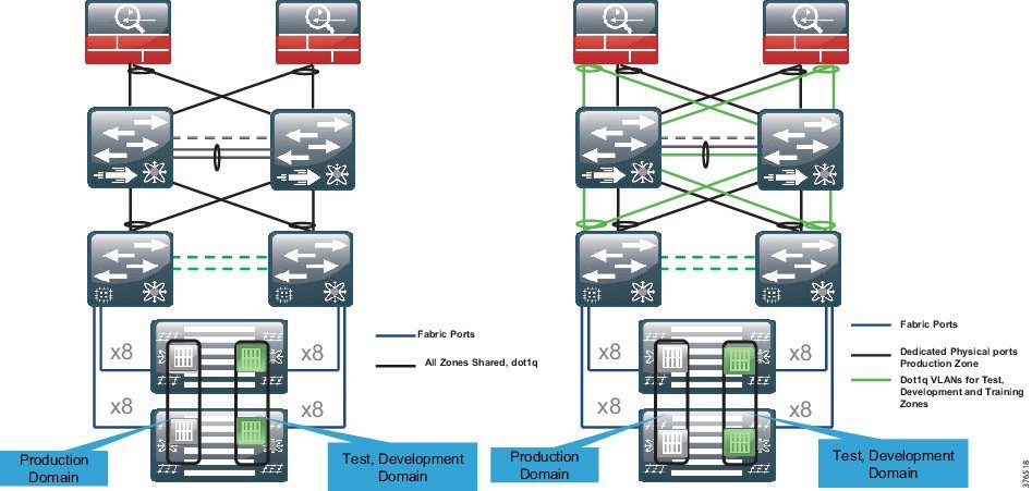
The Connected Pipeline architecture recognizes that further segmentation above pure logical segmentation may be a business- or risk-associated requirement. Therefore, a second option for the segmentation may include physical segmentation where the business warrants it.
An example is the production environment that has requirements for an extra level of segmentation in the networking architecture. Physical isolation using dedicated non-shared ports may be deployed for this zone. This may also be a requirement for the DSS environment. Therefore, dedicated physical ports from the UCS system through to the 3524 switches and the ASA firewalls could be deployed for the production environment.
802.1q trunking of VLANs will be configured on shared ports for the less essential services. For example, the test, development, and training environments will use this method.
Figure 3-4, Option 2 provides a view of the physical/logical segmentation seen in the design at the networking level. The production servers (Gray) housed on separate UCS chassis hit the Fabric Interconnects via a unified fabric. The VLAN is then extended through the switch and to the ASA firewall on its own dedicated physical cabling and port. The test, training, and development zones are transported using logically separate VLANs, but over a shared physical medium using 802.1q trunking.
When looking to use segmentation with more of a physical rather than logical approach, be aware of the port availability on the infrastructure components, specifically the firewalls.
Layer 3 Network Segmentation
Any inter-VLAN routing will require explicit configuration on the firewall. The firewall is acting as the Layer 3 gateway for the servers and will therefore enforce policies for any inter-zone or inter-system traffic. Access lists, rules, and policies will be configured at the firewall to allow or deny communication
The firewalls will have routing enabled to the WAN-facing routers and will provide access to the Enterprise through an Industrial DMZ.
Summary
- VLANs provide the logical segmentation for the network.
- 802.1q trunks and vPC provide shared infrastructure for the logical segmentation.
- Further segmentation above logical segmentation can be provided with dedicated physical ports as described.
- Policy enforcement is at the ASA firewall where the Layer 2 is terminated and the ASA provides the Layer 3 gateway functionality for the Control Center zones.
Compute Segmentation
Figure 3-5 provides an overview of the compute and storage setup. Each environment will have its own set of dedicated servers or server. In the production environment, it is recommended to have a pair of physical servers to provide redundancy. To enhance redundancy, each of these physical servers will be housed in a separate B series chassis. The virtual machines in these environments/zones all belong to the same VLAN and no requirement exists to house a virtual machine/server outside of its dedicated VLAN.
Figure 3-5 Compute and Storage Setup Overview
Virtual Switch (vSwitch)
From a networking perspective, each of the machines in a zone has the capability to see each other as they are in a single VLAN instance. A vSwitch is an existence of a switch housed on the hypervisor to provide typical network switching functions for the Virtual Machines. This is very similar to a standard access switch that would house regular physical compute. A Hyper-V virtual switch has the capabilities to tie a VLAN to a Virtual Machine providing segmentation at the hypervisor. If intra-VLAN traffic requires policies, then ACLs can be applied at this layer to enforce policy within a zone.
Virtual Network Interface Cards (vNICS)
In conjunction with a vSwitch, the Cisco Virtual Interface Cards (VICs) have the capability to create virtual adapters or vNICs. These allow multiple vNICs to be created rather than physical interfaces. This allows separation of traffic where logical segmentation of data traffic from the Virtual Machines can be separated from the infrastructure management traffic.
Summary
- Each environment will have a set of dedicated servers or server.
- In the Production Environment, it is recommended to have a pair of physical servers to provide redundancy.
- Physical pairs of servers will be spread between two UCS Chassis. Chassis redundancy provides an extra level of comfort over pure fabric redundancy.
- Virtual Machines are connected to a vSwitch where VLAN, QoS, and security policies are applied.
- Segmentation is carried through the architecture from the Virtual Machine through the vSwitch, UCS system, Nexus 3524 to the firewalls using VLANs.
Storage Segmentation
This section describes file system management, fiber channel zoning and VSANs, and LUN masking.
File System Management
Each Virtual Machine will have its own dedicated storage for its running environment housed on the storage array. The Microsoft Hyper-V hypervisor's cluster file system management creates a unique Virtual Hard Disk (VHD) per Virtual Machine, ensuring that multiple Virtual Machines cannot access the same VHD sub-directory within the New Technology File System (NTFS) volume, and thus isolating one tenant's VHD from another.
Fiber Channel Zoning and VSANs
Segmentation is enhanced with the configuration of Fiber Channel zoning and Virtual Storage Area Networks (VSAN) in a Fiber Channel storage network. These technologies allow for the physical SAN fabric to be segmented into smaller logical domains.
The architecture will deploy a pair of VSANs. The VSANs will be tied to fabric paths across the infrastructure. This enables the fiber channel redundancy through the use of a Fabric A and Fabric B, which are physically and logically separate.
This partitioning of fabric services greatly reduces network instability by containing fabric reconfigurations and error conditions within an individual VSAN. The strict traffic segregation provided by VSANs helps ensure that the control and data traffic of a specified VSAN are confined within the VSAN's own domain, increasing SAN security and availability. Fiber Channel zoning is deployed to take security to the next layer by providing access control between devices in a VSAN; for example, in the architecture, it allows control and storage policy of storage communications between a host and a storage controller/chassis.
Depending on the security policy and risk assessment, multiple VSANs can be deployed per SCADA zone. Similar to the networking architecture where the networking traffic had its own physical links, the production environment may require its own set of VSANs tied to separate physical SANs. Care must be taken to accommodate the correct equipment to ensure port availability for this architectural approach. This, though, is outside the scope of this CVD.
Figure 3-6 highlights the design within scope. This is the traditional deployment where a VSAN A will be tied to Fabric A, and the VSAN B will be tied to Fabric B. Both storage arrays will be connected using these VSANs/Fabrics.
Figure 3-6 Fiber Channel Zoning Design

LUN Masking
Logical Unit Number (LUN) masking should be configured as an extra level of security at the storage level over VSANs and FC zoning. LUN masking creates an authorization process that restricts storage LUN access to specific hosts on the shared SAN. The storage controllers usually create LUN masking to enforce access policies between hosts and particular LUNS on the storage system.
Summary
- Dual Storage Arrays, each serving different hosts and physical servers on each UCS Chassis
- Segmentation on the storage system using VSANs, FC Zoning, and LUNs
- Standard VSAN A/B mapping to UCS Fabric A and B
- The strict traffic segregation provided by VSANs helps ensure that the control and data traffic of a specified VSAN are confined within the VSAN's own domain, increasing SAN security and availability
- An option to enhance segmentation with extra VSANs to isolate the production storage network from the non-production environments is outside the scope of this document, but is acknowledged as a consideration
Firewall and Industrial DMZ Design
This section describes firewall deployment options, IDMZ concepts, IDMZ, and DSS design.
Overview
The firewalls, as shown in Figure 3-7, provide the following foundational security functions within the pipeline architecture:
- A security boundary between the WAN for connection to the pipeline and the Backup Control Center within the process control network
- Architecture for communicating with the external business and enterprise domain using an IDMZ
- An Intra-Control Center policy between zones and segments as explained in the Network segmentation section earlier
- An IDMZ for operational data that can be accessed by the enterprise, and a secure staging area for patching and anti-virus services
Figure 3-7 Firewall and IDMZ Design
Firewall Deployment Options
The choice of firewall deployment will depend on customer philosophy and user requirements, as detailed earlier. The section highlights three deployment options; this CVD, however, will focus on the consolidated firewall deployment.
Single Consolidated Firewall
The Single Consolidated Firewall provides policy for all communications between zones in the Control Center, including the policies for the DSS/IDMZ, WAN, and any inter-zonal communications between environments. Remote access policies are enabled on these firewalls to provide the access into the process domain. All services are deployed as a single pair of ASA devices, providing a single point of administration.
Multi-Context Firewalls
Multi-Context Firewalls can be thought of as virtual instances of firewalls on the same physical device. Each context provides an independent device with its own security policy, interfaces, and administration. Within the Control Center architecture, this would allow differing policies and administration for the DSS/IDMZ from the rest of the Control Center, akin to a totally separate firewall. The limitations to the deployment are detailed below:
- Redundancy/failover supports active/active mode only
- Multiple Context mode does not support the following features:
–![]() OSPFv3 (OSPFv2 is supported)
OSPFv3 (OSPFv2 is supported)
The ASA family has supported multi-context firewalls since its initial release; however, no virtualization support for Remote Access has existed with multi-context configured until now. From 9.5.2, multi-context-based virtualization has support for VPN Remote Access connections to the ASA. For more information, please refer to the ASA: Multi-Context Mode Remote-Access (AnyConnect) VPN at the following URL:
- http://www.cisco.com/c/en/us/support/docs/security/asa-5500-x-series-firewalls/200353-ASA-Multi-Context-Mode-Remote-Access-A.html

Note![]() If the supported features are not sufficient to support remote access VPN, a separate set of firewalls would need to be deployed. This may lead the customer to physically separate firewalls if administrative separation is required since multiple physical firewalls would need to be deployed (two sets of firewalls).
If the supported features are not sufficient to support remote access VPN, a separate set of firewalls would need to be deployed. This may lead the customer to physically separate firewalls if administrative separation is required since multiple physical firewalls would need to be deployed (two sets of firewalls).
Physically Separate Firewalls
Multiple physical firewalls may be deployed. A separate pair of firewalls are deployed for the IDMZ/DSS and remote access, and a second pair of firewalls provide the policy for the remaining zones and WAN communications. This could have differing administration and administrators.
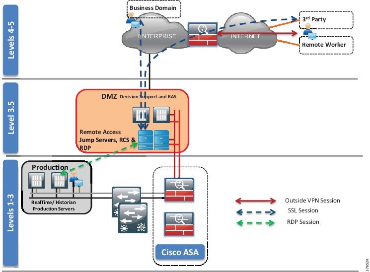
Industrial DMZ Concepts
Services and data need to be exchanged between the untrusted Enterprise network and the trusted Process Control Network (PCN). This exposes near real-time and historical information to the Enterprise and allows for better business decisions. Systems located in the Industrial DMZ bring all the data together for company personnel in a near real-time system, allowing the ability to forecast and change daily operations that will generate the most revenue for the company.
In aligning with standards such as IEC 62443/ISA99 and ISA 95, a requirement exists in the Process Control Domain (PCD) to provide strict policy enforcement between the trusted Levels 1-3 of the PCD and the untrusted Levels 4-5 of the Enterprise/business domain. No direct communications are allowed between the Enterprise and PCD. The IDMZ commonly referred to as Level 3.5 provides a point of access and control for the access and exchange of data between these two entities. The IDMZ architecture provides termination points for the Enterprise and the process domain and then has various servers, applications, and security policies to broker and police communications between the two domains.
The following are key guidelines and concepts for the IDMZ:
- No direct communications should occur between the Enterprise and the PCD.
- The IDMZ needs to provide secure communications between the Enterprise and the PCD using mirrored or replicated servers and applications.
- The IDMZ provides for remote access services from the external networks into the PCD.
- The IDMZ should a security barrier to prevent unauthorized communications into the PCD and, therefore, create security policies to explicitly allow authorized communications.
IDMZ and DSS Design
Within the context of the Connected Pipeline architecture, the IDMZ houses the DSS, which provides proxy or brokering services for communications between the enterprise and PCD.
A historical and real-time server is located within the IDMZ that interacts with servers within the Level 3 PCN production environment. The information from the PCN is replicated to the servers in the IDMZ so that services such as Remote Client Server can facilitate the passing of real-time and historical information to the IDMZ.
Remote access servers such as a remote desktop gateway are also situated in the IDMZ. This allows for a secure method to communicate with the PCD for remote workers or contractors that may require access. Other services would typically include operating system patch server, anti-virus server, and secure FTP server/gateway: in fact, any service that requires information or interaction with Level 4 and above to assist with the day-to-day operations of the Pipeline Control Center.
Policy
The firewalls are recommended to follow the practice of denying any service unless explicitly configured. All services must be identified and rules put in place to allow the communications through the firewall. This requires that any TCP/UDP port numbers are identified so that this explicit configuration can be created.
Security Levels
The interfaces on the ASA require security levels to define the level of trust associated with that particular interface. The security level is set for values of 0-100 where the higher the value, the more trusted the interface. Implicit communications are allowed between higher to lower security levels. However, it is recommended to explicitly configure policies to overwrite the implicit nature of security levels. Therefore, within the Control Center firewall design, the security levels are really nothing other than an identifier of trust for an interface.
VLAN Segmentation
VLAN segmentation, as explained earlier, is a common component in the security framework to assist with isolating services in the Control Center architecture. This can be extended into the IDMZ architecture too. In creating several VLANs within the IDMZ and DSS environment, the servers can be isolated so that, if compromised, the servers within the VLAN container can be restricted from impacting other servers within the IDMZ.
Remote Access Overview
The business and security practices of a customer may influence the chosen method for remote access. The methods discussed in this section focus on using remote desktop services to access the environment. This is not an exclusive list and the client-based VPN service using Cisco AnyConnect could be used to offer another method to access the IDMZ or process domain.
Schneider Electric Remote Client Service
The Schneider Electric Remote Client Service (RCS) provides a means for secure remote access to the SCADA applications. The client is required to be a member of the control system domain. See Figure 3-8.
Figure 3-8 Schneider Remote Client Service Design
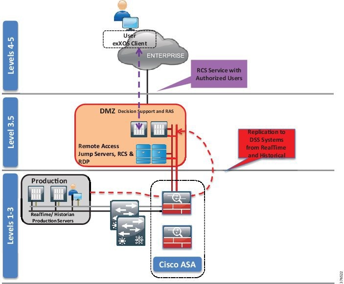
- The client communicates with the RCS server in the IDMZ through ports explicitly configured on the firewall. The corporate network is prevented from seeing any other server.
- For individual users remotely accessing the Decision Support SCADA system applications, user access management is handled through a secured RCS server after establishing a VPN connection to the SCADA system. The client initiates a connection using an Operating System client and is authenticated for application access via an instance of Active Directory.
- The RCS server queries data from the RealTime and Historical services running within the Decision Support/IDMZ on behalf of the user.
- The Historical and RealTime services in the Decision Support/IDMZ, in turn, receive their data from the operational instances of the Historical and RealTime services running in the Production Environment through replication services.
- All communication takes place between the client and the RCS server over a single port with SSL-encrypted TCP/IP.
Clientless VPN Remote Desktop Protocol Plug-in
The ASA has the capabilities to terminate remote VPN connectivity with use of a web browser and SSL encryption. This is termed as a clientless VPN because no forced download or requirement exists for the end user to have a specific client installed for VPN access (Cisco also offers a client-based VPN using Cisco AnyConnect). See Figure 3-9.
Figure 3-9 Clientless VPN RDP Plug-in
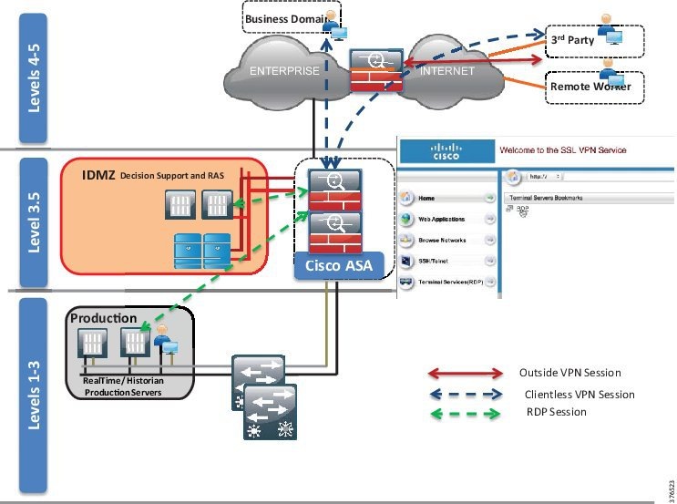
- The user, if outside of the corporate network, creates a VPN session to the corporate firewall. (Policy, authentication, and authorization would all have to be worked with the enterprise IT team to allow this connection.)
- The user opens a browser and enters the IP address of the IDMZ Firewall. Once connected, the user is authenticated against the Active Directory in the IDMZ.
- After authentication, the user is presented with a web portal and a preconfigured bookmark based on the user's security profile. In this instance, this is an Remote Desktop Protocol (RDP) bookmark to a server in the IDMZ or could be as seen an RDP session into the Decision Support SCADA system.
- The Remote Desktop session is opened from the firewall to the defined server in the bookmark and the RDP session is now presented back to the user.
- No direct access to the environment exists.
Remote Desktop Gateway Service
An alternative to using the clientless VPN and RDP plug-in is to position a Remote Desktop Gateway in the IDMZ. This server can broker RDP communication between the client outside of the IDMZ to servers in the IDMZ or into the PCD. See Figure 3-10.
Figure 3-10 Remote Desktop Gateway
The user, if outside of the corporate network, creates a VPN session to the corporate firewall. (Policy, authentication and authorization would all have to be worked with the enterprise IT team to allow this connection.)
The user opens the RDP client from a computer. The user enters the address of the specific host to which they wish to connect and the address of the gateway server. (The firewall will only allow access to the gateway server in the IDMZ so the direct access to the server would be denied.)
The gateway server authenticates the user and, once authenticated, brokers RDP communication between the client and the server in the PCD or IDMZ.
Inter-Control Center Firewall Considerations
An overview of Control Center-to-Control Center communications can be found in Use Case: SCADA Real-time /Near Real-time Operations. Services for replication of data between the primary and backup Control Center and supporting services such as Active Directory need to be explicitly configured. This configuration restricts communications to only those ports required for Domain Controller communications and OASyS DNA functionality. Firewall Access Controls must be configured to control traffic bi-directionally.
Other services such as remote access may be required between Control Centers and should be configured if warranted.
Pipeline Communication Firewall Considerations
To allow communication between the production environment and the pipeline devices, explicit IP addresses and TCP/UDP port numbers should be identified for the protocols, services, and devices that require communication. Depending on the SCADA protocols used, this could be different for every customer.
Intra-Control Center Firewall Considerations
The firewall is the policy point for configuration of any intra-Control Center communication. In keeping with the segmentation policy, any inter-VLAN traffic should be explicitly configured on the firewall if communications is required between zones.
Summary
- Firewall policies for the SCADA Zone, IDMZ/DSS (including Remote Access and Enterprise interaction), and Development and Test environments.
- Traffic and route policies applied at the ASA Firewall to prevent inter-zone traffic, unless explicitly configured.
- Operational Telecoms WAN to SCADA and vice versa: ACLs will be explicitly configured to permit traffic between the WAN and the SCADA zone at the ASA.
- Replication between Control Centers will require specific ports to be opened at the firewalls of both Control Centers. The Schneider Electric Oil and Gas OASyS DNA 7.6 Firewall Requirements document contains the specific ports required between Domains (Zones) and physically-separated locations.
- Using the instances of replicating historical and real-time data, the servers in the SCADA zone will be explicitly permitted to allow traffic to the DSS in the IDMZ.
- RCS port will be open to allow corporate users to access the DSS for the purpose of reading the historical and real-time data.
- Clientless VPN and RDP Gateway services are alternatives for remote access to the RCS from Schneider Electric.
- DSS/IDMZ could be deployed with extra VLAN segmentation within the environment to provide further isolation of servers.
Network Infrastructure Security
To provide extra levels of security, basic infrastructure mechanisms exist to help protect the switching infrastructure. The guidelines described in this section should be followed.
Shutdown Unused Ports
Place any ports not being used into a shutdown state. For the purpose of a switch, add the switchport VLAN command with an unused VLAN (not VLAN 1) so that if a port is accidentally activated, it will not affect any deployed VLANs.
Trunk Ports
The following best practices should be practiced or order to prevent such attacks as VLAN hopping.
When configuring trunk ports, turn DTP off and explicitly configure trunking on the infrastructure ports. Use a dedicated VLAN ID on all trunk ports. Do not use VLAN 1 for anything and configure all tagged mode for the native VLAN on trunks. Only add the VLANs that are required on the trunk ports.
DHCP Snooping
If servers or workstations in the architecture are using Dynamic Host Configuration Protocol (DHCP), then DHCP snooping and Dynamic ARP Inspection (DAI) should be considered.
DHCP snooping is a security feature that acts like a firewall between untrusted hosts and trusted DHCP servers. The DHCP snooping feature performs the following activities:
- Validates DHCP messages received from untrusted sources and filters out invalid messages
- Rate-limits DHCP traffic from trusted and untrusted sources
- Builds and maintains the DHCP snooping binding database, which contains information about untrusted hosts with leased IP addresses
- Uses the DHCP snooping binding database to validate subsequent requests from untrusted hosts
Other security features, such as DAI, also use information stored in the DHCP snooping binding database. Refer to the "Configuring DHCP" chapter of the Consolidated Platform Configuration Guide, Cisco IOS XE 3.7E and Later (Catalyst 3850 Switches) at the following URL:
Dynamic ARP Inspection (DAI)
DAI is a security feature that validates ARP packets in a network. DAI intercepts, logs, and discards ARP packets with invalid IP-to-MAC address bindings. This capability protects the network from some man-in-the-middle attacks. Please refer to the "Configuring Dynamic ARP Inspection" chapter of the Consolidated Platform Configuration Guide, Cisco IOS XE 3.7E and Later (Catalyst 3850 Switches) at the following URL:
Port Security
Port security limits the amount of MACs on a particular interface. This helps to prevent threats such as MAC attacks. Port security should be enabled on access ports. Port security with dynamically learned and static MAC addresses can be used to restrict a port's ingress traffic by limiting the MAC addresses that are allowed to send traffic into the port. When secure MAC addresses are assigned to a secure port, the port does not forward ingress traffic that has source addresses outside the group of defined addresses. Port security should be enabled on the 3850 for the workstation connectivity. Port security is currently not available on the Nexus 3000 Series.
Details of the port security feature and configuration guidelines can be found in the "Configuring Port-Based Traffic Control" chapter of the Consolidated Platform Configuration Guide, Cisco IOS XE 3.7E and Later (Catalyst 3850 Switches) at the following URL:
Traffic Storm Control
A traffic storm occurs when packets flood the LAN, creating excessive traffic and degrading network performance. The traffic storm control feature can be used to prevent disruptions on Ethernet interfaces by a broadcast, multicast, or unknown unicast traffic storm.
For guidance and configuration for this feature, refer to “Configuring Traffic Storm Control” of the Cisco Nexus 3000 Series NX-OS Layer 2 Switching Configuration Guide, Release 7.x at the following URL:
- http://www.cisco.com/c/en/us/td/docs/switches/datacenter/nexus3000/sw/layer2/7x/b_Cisco_Nexus_3000_Layer_2_Switching_Config_7x/b_Cisco_Nexus_3000_Layer_2_Switching_Config_7x_chapter_01100.html
For port-based traffic control on the 3850, refer to the “Configuring Port-Based Traffic Control” chapter of the Consolidated Platform Configuration Guide, Cisco IOS XE 3.7E and Later (Catalyst 3850 Switches) at the following URL:
Infrastructure Management
Most of the networking management protocols that are used are insecure (such as SNMP, Telnet, and FTP). The secure variants of these protocols (SSH in place of Telnet, SNMP V3) should be used.
Use OOB management to manage the infrastructure. The preferred method is to run the management infrastructure separately from the main Control Center infrastructure. If this is not possible, use a dedicated VLAN for management.
Protect the user access and privilege levels of all the networking devices. AAA should be enabled. The preferred method would be to use a Terminal Access Controller Access-Control System Plus (TACACS+).
Control Plane Policing (CoPP)
To protect the control plane from being overwhelmed, the Cisco devices have Control Plane Policing (CoPP) features. In the case of the Nexus 3524 switch, the device segregates different packets destined for the control plane into different classes. Once these classes are identified, the Cisco NX-operating system device polices the packets, which ensures that the supervisor module is not overwhelmed.
For guidance for CoPP on a Nexus 3524 switch, refer to the “Configuring Control Plane Policing” chapter in the Cisco Nexus 3000 Series NX-OS Security Configuration Guide, Release 7.x at the following URL:
Availability
A foundational requirement for the Control Center implementation is to provide a highly available infrastructure. This section discusses some of the technologies required to implement this requirement. The goal of this section is to provide the technologies that will be validated in the design so that those implementing a Control Center architecture can make informed decisions for the best implementations that will address their business requirements and objectives.
Figure 3-11 highlights the key redundancy principles described in Chapter2, “Connected Pipeline Architecture”
Figure 3-11 Key Redundancy Principles
- Dual servers for all critical components
- Dual application instances in a hot/standby
- Dual networking platforms, including routers, switches, firewalls, and Fabric Interconnects
- Storage redundancy incorporating RAID, controller, and chassis redundancy where appropriate
- Dual SANs
- Multiple data communication paths across the network
- Using enhanced resiliency technologies provide fast failover from active to standby components
- Constant update of information between hot/standby, mirrored servers, and applications
- QoS to provide prioritization of key network traffic and data
- Process and procedures to guide quick replacement of failed devices in situations where redundancy may have not been provided
Network Redundancy
Figure 3-12 depicts network redundancy.
Figure 3-12 Network Redundancy
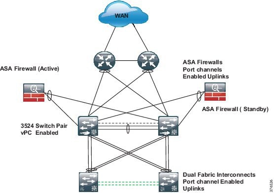
Port Channel
A port channel bundles individual links into a channel group to create a single logical link that provides the aggregate bandwidth of up to eight physical links. If a member port within a port channel fails, traffic previously carried over the failed link switches to the remaining member ports within the port channel.
Port channels are configured as highlighted in Figure 3-12 at the Firewalls and the Fabric Interconnects.
Virtual Port Channel
vPCs allow multiple links to be used between a port channel-attached device and a pair of participating switches. The two Nexus 3524 switches act as vPC peer endpoints and look like a single logical entity to the port channel-attached devices. vPC should be enabled to provide link redundancy and optimal link bandwidth utilization between the Nexus 3K nodes and the following devices:
A vPC provides the following benefits:
- Allows a single device to use a port channel across two upstream devices
- Eliminates Spanning Tree Protocol (STP) blocked ports
- Provides a loop-free topology
- Uses all available uplink bandwidth
- Provides fast convergence if either the link or a switch fails
- Provides link-level resiliency
- Assures high availability
Details for the vPC feature and configuration can be found in "Configuring Virtual Port Channels" in the Cisco Nexus 3548 Switch NX-OS Interfaces Configuration Guide, Release 6.x at the following URL:
ASA Redundancy
Two ASA firewalls in the consolidated architecture provide the policy point for all communications in the Control Center. Layer 3 interfaces, as previously mentioned, are enabled on the firewall and act as the Layer 3 gateway to police traffic between all of the zones in the Control Center and between the Control Center and the WAN. The firewalls are deployed as an active/standby pair.
Summary
Compute Redundancy
This section includes information about Fabric redundancy, end host node, and SCADA server connectivity and redundancy.
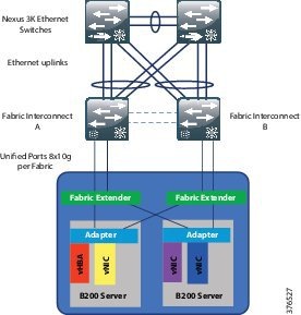
Fabric Redundancy
A fully redundant Cisco Unified Computing System consists of two independent fabric planes: Fabric A and Fabric B. Each plane consists of a central Fabric Interconnect (Cisco UCS 6200 Series Fabric Interconnects) connected to an I/O module (Fabric Extender) in each blade chassis. The two Fabric Interconnects are completely independent from the perspective of the data plane
All network endpoints, such as HBAs, vNICs, and management entities such as Cisco Integrated Management Controllers (IMCs; formerly referred to as baseboard management controllers, or BMCs), are dual-connected to both fabric planes. See Figure 3-13.
End Host Mode
In end-host mode, Cisco UCS presents an end host to an external Ethernet network. The external LAN sees the Cisco UCS Fabric Interconnect as an end host with multiple adapters. The uplink ports appear as server ports. This mode is the default and recommended configuration if the upstream device is Layer 2 switching.
End-host mode features include the following:
- STP is not run on both the uplink ports and the server ports.
- MAC address learning occurs only on the server ports; MAC address movement is fully supported.
- Links are active/active regardless of the number of uplink switches.
- The system is highly scalable because the control plane is not occupied.
More details related to fabric redundancy and end host mode can be found in Cisco Unified Computing System Ethernet Switching Modes at the following URL:
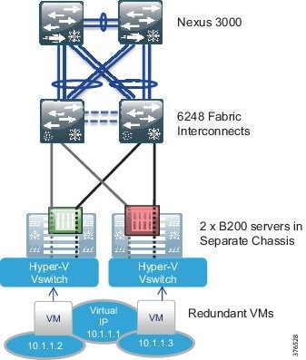
SCADA Server Connectivity and Redundancy (Virtual Machines)
Within the production environment, pairs of B series servers, one in each of two chassis, will exist. Each of these servers will be running duplicate Virtual Machines for each service: for example, two Virtual Machines for the real-time service and two Virtual Machines for the historical. These Virtual Machine pairs will be configured to run on separate physical servers that will be located on separate UCS Chassis.
These two virtual servers will be configured with a single vNIC, which is not the norm for this application. Dual NICs and NIC teaming are normally applied. This is not required in this virtual environment where the Hyper-V virtual switch is deployed. The virtual switch will provide a single vNIC to each virtual server. The vSwitch will have redundant connectivity to the UCS Fabric Interconnects through the use of Fabric Failover.
From an addressing standpoint, each server will be configured with an IP within the same address space, but will communicate with the other SCADA components through its virtual IP. Figure 3-14 gives a representation of the design.
Figure 3-14 SCADA Server Connectivity and Redundancy Design
Storage Redundancy
The storage redundancy follows the same consistent approach to the other areas of availability within the architecture consisting of hardware and path redundancy. See Figure 3-15.
Figure 3-15 Storage Redundancy Design
Hardware Redundancy
Redundancy is carried throughout the architecture at the hardware level. We will take the example of a production environment in Figure 3-15 to explain the hardware redundancy modeled.
Server Redundancy
Two physical UCS B200 servers will house the hot and standby instances of the production application Virtual Machines. A hot instance will exist in one physical server and its standby instance will exist in a separate physicals server. These two servers are located in different UCS Chassis, as depicted in the figure, promoting chassis redundancy. Both servers are equipped with dual-port adapters.
UCS Fabric Interconnects
Two 6200 series Fabric Interconnects exist in the architecture. These provide the management and communications for the UCS B series and 5108 UCS chassis. The pair of 6200 Fabric Interconnects form a single, highly available management domain. The pair of fabrics interface with the SAN and the Ethernet network and provide active/active access to both the storage and Ethernet networks while acting as an active passive mode for the management of the UCS system.
Storage Chassis and Controllers
Two storage chassis will exist in the architecture. These will be equipped with dual controllers to provide redundancy within a chassis.
Redundant SAN
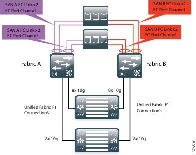
Within storage networking, it is a standard best practice to provide two completely separate SAN fabrics, providing two distinct paths between the compute and the storage. Within this design, a minimum of two VSANs will be created on the UCS system that map to the separate fabrics. Each of dual fabrics in this architecture are directly attached to the storage arrays. One fabric will provide connectivity for Fabric A and one for Fabric B. VSANs, as described earlier, extend SAN networking concepts to create logical segmentation on the same physical infrastructure. Figure 3-16 highlights FC port channels. This is the same concept as in Ethernet port channels where multiple physical links are bundles together to provide one logical link.
It is worth noting that both Fabrics and SANs are active and passing traffic between the hosts and storage. This is an active/active, not active/standby, model.
Figure 3-16 Redundant SAN Design
Multipath
Multipath software is loaded on top of an operating system and provides a layer that sits between the operating system and storage adapters. The multipath software closely monitors all physical paths and storage presentations while load-balancing SAN traffic across the available HBAs and fabric paths. This software layer also accomplishes failover should an HBA, path, or upstream device fail.
Summary
- UCS provides storage redundancy starting at the server with dual port adapters per host.
- Two physical servers house the hot and standby instances of the production application Virtual Machines. A hot instance in one physical server and its standby instance will occur in a separate physical server.
- Each server in a server pair is housed in a separate UCS Chassis.
- Connectivity will occur through a redundant fabric to a pair of Fabric Interconnects.
- Two storage chassis will be directly connected to the Fabric Interconnects using a redundant SAN A/B architecture.
- The guest operating systems and storage are pinned to a specific host to ensure physical redundancy and dedicated server resources.
- A RAID 1 hardware mirroring solution is used to mirror all historical databases onto online disks available to the SCADA system.
- All historical databases on disks are mirrored.
- Two-node clustering is configured for the historical servers' redundancy.
Schneider Electric OASyS Application Design Application Redundancy
This section includes information about Virtual Machine redundancy, SQL SAN storage hardware mirroring, virtual guest storage, Microsoft SQL server-based Historian, and operator workstation connectivity.
Virtual Machine Redundancy
As the required redundancy mechanisms are built into the OASyS software and applications, no requirement exists to configure Virtual Machine redundancy such as Hype-V live migration in the Schneider Electric and Cisco Control Center architecture. The OASyS applications are provided in state machine-aware pairs and replicate required memory segments between the virtual guests. System monitors check critical components for failures and take the least intrusive course of action to recover from any failure
SQL SAN Storage Hardware Mirroring
A RAID 1 hardware mirroring solution is used to mirror all historical databases onto online disks available to the SCADA system. All historical databases on disks are mirrored, so that a failure of a disk does not cause a failure of a particular historical database. When a disk fails, the mirrored disk has the same copy of data as the master disk. This disk makes available historical data for the failed disk to the SCADA system. Once the failed disk is replaced, the SAN software automatically copies the information from the mirror disk back onto the new disk.
Virtual Guest Storage
Similar to historical data storage, the Virtual Hosts and Virtual Guests are stored on a storage array on the SAN. A RAID 5 set of disks is used to boot the host operating system and another RAID 5 group of disks is used to boot the guest operating systems.
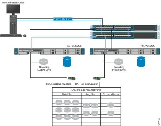
Microsoft SQL Server-Based Historian
As the SCADA system historian is not critical to safe operations, a Microsoft Hot/Standby Cluster is used to share SQL-based data between the two OASyS Historical servers at one site. Microsoft SQL Server Cluster provides both automatic and manual failover capability for SQL Server services to another node in case the active node is down. The active node can be down due to an operating system or a hardware failure, in which case the automatic failover to an available node on the same cluster can occur and the users will start using the application through the failover node. SQL Server services can be manually moved to a different node at times when a planned maintenance like an operating system upgrade or patch maintenance is required on the active node. Figure 3-17 illustrates the combined architecture of the OASyS Historian and Microsoft SQL Cluster.
Figure 3-17 OASyS Historian and Microsoft SQL Cluster Combined Architecture
Operator Workstation Connectivity
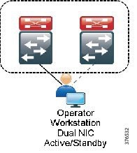
The operator workstations are connected within the SCADA zone. These stations will be configured with dual NICs and connected to traditional Catalyst 3850 stackable switches. Generally, the workstations will be in a different physical location so it will be required to extend the VLAN from the 3524 Nexus switches to the Catalyst. The NICs on these workstations will operate in an active/standby configuration and each NIC will be connected to a different stackable 3850. See Figure 3-18.
Figure 3-18 Operator Workstation Connectivity
Network Management
Management and diagnostics involves tools, applications, and devices used to monitor, configure and maintain the Control Center architecture. Although a typical pipeline network does not drastically change after deployment, the network needs to be maintained and managed. The business practices and levels of expertise, however, may dictate the management practice, roles, and responsibilities of the system. This section describes the platforms, technologies, and practices used.
Cisco UCS Manager
Cisco UCS Manager resides as embedded software on the Cisco UCS Fabric Interconnects, Fabric Extenders, servers, and adapters. No external management server is required, thereby simplifying administration and reducing capital expenses for the management environment. The communication between the manager on the Fabric Interconnect and the subsidiary functions found in the Fabric Extenders, chassis, servers, and adapters are built in and automatic.
UCS Manager provides an intuitive GUI, a CLI, and a robust API to manage all system configuration and operations. Cisco UCS Manager enables storage, networking, and server maintenance staff to collaborate easily on defining service profiles for applications while preserving subject matter expertise and roles. Key features include:
- Supports Cisco UCS B-Series blade and C-Series rack servers, UCS Mini, Cisco Composable Infrastructure and Cisco HyperFlex hyperconverged infrastructure
- Unified, embedded, policy-driven management programmatically controls server, network, and storage resources, so that they can be efficiently managed at scale through software
- Works with HTML 5, Java, or CLI GUIs
- Auto Discovery can detect, inventory, manage, and provision system components that are added or changed
- An open XML API facilitates integration with third-party systems management tools
- Role-based administration builds on existing skills and supports collaboration across disciplines. For more information, see “Cisco UCS Manager” at the following URL:
–![]() http://www.cisco.com/c/en/us/products/servers-unified-computing/ucs-manager/index.html
http://www.cisco.com/c/en/us/products/servers-unified-computing/ucs-manager/index.html
Cisco Adaptive Security Device Manager
Cisco Adaptive Security Device Manager (ASDM) can be accessed directly with a Web browser from any Java plug-in-enabled computer on the network, providing security administrators with rapid and secure access to their Cisco ASA Firewalls. ASDM allows the user to configure, monitor, and troubleshoot Cisco firewall appliances with a user-friendly application. Ideal for small or simple deployments, the Cisco ASDM provides the following:
Out of Band Management
A separate Out of Band (OOB) network should be deployed to provide a dedicated infrastructure to support the management traffic. The OOB network segment hosts console servers, network management stations, AAA servers, analysis and correlation tools, NTP, FTP, Syslog servers, network compliance management, and any other management and control services. An OOB management network should be deployed using the following best practices:
- Provide network isolation
- Enforce access control
- Prevent data traffic from transiting the management network
- Enforce secure use of network management traffic (SSH, SNMP v3)
If an OOB network is not viable, then a dedicated VLAN should be used for the management network following the same best practices above and classifying/prioritizing management traffic using QoS.
Role-Based Access Control
Role-Based Access Control (RBAC) is a method of restricting or authorizing system access for users based on a user's role. This role consists of privileges that will be assigned to the user. These privileges can be very granular; for example, a user can be restricted from accessing particular commands and strings. This becomes very useful in the Control Center environment, especially in the UCS domain. With the consolidated nature of the UCS system, varying users with differing expertise can access the platform. Using RBAC, we can create server, storage, and network administration privileges and roles. The UCS system can even take this to the next level using Locales. For example, a user with the Server Administrator role for the Test and Development environment could update server configurations in that environment, but could not update server configurations in the Production environment unless the locales assigned to the user include the access privilege.
Summary
- OOB Management should be used where possible. Dedicated VLANs should be used if In-band Management is used.
- Use secure methods to provide extra security for network management traffic. SSH and SNMP v3 are examples.
- Provide visibility of events, faults, and performance of the network to the operators in the Control Center using Syslog and SNMP.
- Enable RBAC for access to the infrastructure components.
Time Synchronization
All components of the SCADA system architecture must be time synchronized. Time synchronization is critical for event correlation and analysis of events in the pipeline network. Therefore, all infrastructure components must be enabled with Network Time Protocol (NTP) and configured to a central source. A Network Time Server (NTS) is leveraged for Windows time synchronization at each site (for example, one at the Primary Control Center and one at the Secondary Control Center). The NTS can serve accurate time to any system running an NTP or Simple Network Time Protocol (SNTP) client and can support 200,000 network clients (such as workstations, servers, and routers) with an NTP timestamp accuracy of <10 microseconds. Each time the client will require access to the IP address of the network time server.
The NTS derives accurate time from the atomic clocks aboard the GPS satellite system. To obtain the time, it uses the Code Division Multiple Access (CDMA) mobile telecommunications network used by many cellular telephones. This means the antenna can be conveniently located anywhere a cell phone signal is available.
 Feedback