Dual Fabric Architecture for Virtualized Industrial Applications
Available Languages
Bias-Free Language
The documentation set for this product strives to use bias-free language. For the purposes of this documentation set, bias-free is defined as language that does not imply discrimination based on age, disability, gender, racial identity, ethnic identity, sexual orientation, socioeconomic status, and intersectionality. Exceptions may be present in the documentation due to language that is hardcoded in the user interfaces of the product software, language used based on RFP documentation, or language that is used by a referenced third-party product. Learn more about how Cisco is using Inclusive Language.
- US/Canada 800-553-2447
- Worldwide Support Phone Numbers
- All Tools
 Feedback
 Feedback
vPLCs and the shift in control boundaries
Solution Benefits of the Dual Fabric SD-Access Architecture
Dual SD-Access Fabric Architecture
Industrial Ethernet Communication Characteristics
Traffic Model for Manufacturing Applications
Dual SD-Access Fabric Architecture Overview
Why Dual Fabric Starts with SD-Access
Creating Dual SD-Access Fabrics for Critical Applications
Architecture Takeaways for vPLC Workloads
PRP Fundamentals and Terminology
Solution Architecture Components
Validated Hardware and Software
Dual SD-Access Fabric Networking Design
Management and Policy Plane Considerations
Real-Time Traffic Connectivity to Dual Fabrics
Non-Real-Time Traffic Handling
Time Distribution Connectivity for Safety PLCs
Summary of Architectural Characteristics
PRP Operation Across Dual SD-Access Fabrics
PRP RedBox Placement in the Dual SD-Access Fabric Architecture
Layer 2 and Layer 3 Boundaries in Dual SD-Access Fabric
Example: Layer 2 and Layer 3 Boundaries for PRP and Non-PRP VLANs
PRP Supervisory Frames and Default Behavior
Implications in SD-Access Based Fabrics
PRP supervision VLAN aware mode for Scalable Deployments
Example: PRP Scale on Centralized Data Center for vPLC
Operational Guidance for PRP supervision VLAN aware mode Configuration
Time-Critical Industrial Control Traffic Priority Model
Time-Critical Industrial Control Traffic at the Industrial Access Layer
Time-Critical Industrial Control Traffic and VXLAN Encapsulation
Time-Critical Industrial Control Traffic Handling Inside the SD-Access Fabric
Restoring Layer 2 Priority for Time-Critical Industrial Control Traffic at Fabric Egress
Summary: End-to-End PROFINET Frame Handling
(1) Industrial Access – Native PROFINET Frame
(2) SD-Access Fabric Ingress – Classification and VXLAN Encapsulation
(3) Transit Across the SD-Access Fabric – Routed Transport with Preserved Priority
(4) SD-Access Fabric Egress – Decapsulation and Priority Preservation
(5) Virtual Switch to vPLC – Layer 2 Delivery
Consistency Across Both Fabrics
Key QoS Design Principles for Dual SD-Access Fabric Architecture
Layer 2 Flooding and Multicast Requirements
Catalyst IE3400 Commissioning and Replacement Procedures
Operational Considerations for PEN/RedBoxes
Placement of Industrial Ethernet Switches in SD-Access Based Manufacturing Networks
Design Considerations and Operational Constraints
IP Directed Broadcast for Silent Host Use Cases
IT and OT Collaboration and Shared Infrastructure Considerations
Collaboration and Operational Alignment
Shared vs. Separated Infrastructure
Silent Hosts in OT Environments
NAT Below the Fabric Edge: OT-Specific Considerations
Dual SD-Access Fabric Architecture Security Design
Macro-segmentation for OT Security
Micro-segmentation for Manufacturing Networks
How OT Segmentation Differs from Campus Networks
TrustSec Segmentation Design Principles for OT Networks
TrustSec Classification in OT Environments
TrustSec Propagation Across SD-Access and Non-Fabric Domains
TrustSec Enforcement Models in OT Designs
Scale and Platform Considerations
Default-Deny Policy Considerations in SD-Access Based Manufacturing Networks
Cyber Vision for OT Visibility in SD-Access Based Manufacturing Networks
Cyber Vision Deployment in SD-Access Architecture
SD-Access Specific Considerations for Cyber Vision Integration
Secure Equipment Access (SEA) in SD-Access Based Manufacturing Networks
Integration of SEA with Cisco Cyber Vision
SEA Deployment in SD-Access Architecture
Bandwidth, Replication, and Platform Sizing
Failure and Recovery Scenarios
Management Plane Sizing, Latency, and Operational Scale
Layer 2 Flooding and Underlay Multicast Scale
vPLC and Data Center / Virtualization Integration
Control Plane and Border Node Scale
Design Recommendations Summary
Validation Summary and Results
Validation Scope and Objectives
Traffic and Congestion Validation
Failure and Recovery Validation
Latency and Jitter Measurements
As an initial step towards software-defined automation, manufacturing environments are increasingly adopting virtualization architectures to improve scalability, lifecycle management, and integration with advanced analytics and AI-driven applications. They are virtualizing a range of compute focused devices and applications including engineering workstations, human-machine interfaces (HMIs) and even the brains of the industrial automation systems, the programmable logic controller (PLC). While virtualization delivers clear benefits, it also fundamentally alters the assumptions under which traditional PLC networks were designed. Control workloads that were once tightly coupled to a local backplane or a single access switch now depend on a shared, distributed Ethernet infrastructure and take advantage of running on more capable server systems.
This Cisco Validated Design (CVD) provides architectural guidance for deploying dual independent Ethernet fabrics to support virtualization, and especially vPLC workloads in manufacturing environments. The design focuses on preserving bounded latency and jitter, fault isolation, and operational behavior, while integrating critical capabilities such as control traffic prioritization with Quality of Service (QoS), hitless network resiliency with the Parallel Redundancy Protocol (PRP), industrial cybersecurity with Cisco Cyber Vision for visibility, remote access with Secure Equipment Access (SEA), and Cisco TrustSec-based segmentation.
vPLCs and the shift in control boundaries
Benefits and Challenges of vPLC Workloads
Virtualizing PLC workloads introduces architectural and operational benefits that extend beyond compute consolidation. When properly designed, vPLC architectures enable greater flexibility, resilience, and lifecycle control while preserving the time-sensitive behavior required by manufacturing applications.
Key Benefits
● Workload Mobility and Flexibility
vPLCs are no longer tied to a specific physical controller or cabinet location. Control workloads can be placed, relocated, or recovered based on operational needs without rewiring field devices or rearchitecting the network.
● Improved Availability and Recovery
Virtualization enables faster recovery from hardware failures through Virtual Machine (VM) restart, migration, or redeployment. This reduces mean time to recovery (MTTR) compared to replacing or reconfiguring physical PLC hardware.
● Simplified Lifecycle Management
Software-based PLCs simplify firmware updates, backups, version control, and rollback. Control logic can be managed using standardized IT workflows while maintaining OT change-control practices.
● Improved Security
Ability to quickly upgrade the software with security updates reducing risks to the application
● Scalability and Resource Efficiency
Compute resources can be shared across multiple control workloads, allowing capacity to be scaled incrementally as production requirements evolve, without overprovisioning dedicated hardware.
● Foundation for Advanced Use Cases
vPLC architectures facilitate closer integration with analytics, AI inference, digital twins, and simulation environments by collocating control workloads with compute and data resources.
● Capital cost savings
By using scalable data center quality server platforms, manufacturers save significant capital expenditures from the ruggedized and limited PLC hardware.
Key Challenges
Traditional PLC architectures rely on implicit assumptions:
● Fixed physical location
● Connected directly to the local network of the industrial devices it’s controlling
● Predictable, minimal network hops
● Limited exposure to shared infrastructure
Virtualization breaks these assumptions. When PLC software is deployed on virtual machines, control logic execution becomes dependent on the behavior of the underlying compute, storage, and network infrastructure. Latency, jitter, congestion, and fault domains that were previously irrelevant now directly influence control system stability.
Solution Benefits of the Dual Fabric SD-Access Architecture
This Cisco Validated Design (CVD) addresses the key challenges of virtual Programmable Logic Controller (vPLC) deployments in manufacturing. It combines dual independent Software-Defined Access (SD-Access) fabrics with industrial-grade redundancy, prioritization, and visibility mechanisms.
Key Technical Features
● Flexible Layer 2 Connectivity
SD-Access uses Virtual Extensible LAN (VXLAN) overlays over a routed Layer 3 network to provide logical Layer 2 adjacency, enabling industrial applications to operate within the same subnet when needed
● Predictable Control Traffic Behavior During Failures
Dual SD-Access fabrics combined with selective PRP eliminate reliance on fabric convergence for time-sensitive control traffic, allowing critical applications to continue operating during link or node failures.
● Strong Fault Isolation
Each fabric operates independently with its own control and forwarding planes, limiting the impact of failures, misconfigurations, or maintenance activities.
● Selective Redundancy Based on Application Needs
PRP is applied only to traffic that requires it, protecting critical flows while avoiding unnecessary bandwidth duplication.
● Consistent End-to-End Traffic Prioritization
Traffic classification and queuing are aligned across industrial access, SD-Access fabrics, and the data center, ensuring uniform treatment of control traffic regardless of location.
● Scalable Visibility Without Additional Infrastructure
Embedded Cyber Vision sensors provide OT visibility across both fabrics without SPAN, additional appliances, or shared forwarding dependencies.
● Strong segmentation (micro and macro) with easy to deploy TrustSec Scalable Group Tags (SGTs) and Virtual Routing Frameworks (VRFs).
Together, these benefits provide a resilient and operationally practical foundation for deploying vPLC workloads in modern manufacturing environments.
The CVD is intended for manufacturing network architects, OT and IT collaboration teams, and system integrators designing production networks where control availability and predictability directly impact safety, quality, and uptime. The guidance reflects real-world factory constraints, combined OT/IT operational models, and the practical challenges of connecting industrial ethernet networks to enterprise and data center infrastructures.
Dual SD-Access Fabric Architecture
Industrial Ethernet Communication Characteristics
Many of the requirements driving the dual fabric architecture originate from the behavior of industrial Ethernet protocols used in manufacturing environments. This CVD focuses on PROFINET, as it is the supported protocol for the validated vPLCs.
PROFINET RT (Real Time), along with other industrial Ethernet protocols, operates directly at Layer 2 of the OSI model, using Ethernet frames identified by a specific EtherType and without a Layer 3 (IP) header. Because this traffic cannot be routed, controllers and field devices must reside within the same Layer 2 domain.
In addition to cyclic real-time traffic, PROFINET relies on non-real-time (NRT) communication for functions such as diagnostics, commissioning, and configuration.
The diagram illustrates how PROFINET uses different communication channels — RT, NRT — aligned with the OSI protocol stack to support real-time control, general traffic, and high-performance deterministic communication. IRT (Isochronous Real Time) is included for reference only. This document focuses on PROFINET RT and NRT, which operate over standard Ethernet. PROFINET IRT requires specialized hardware and is therefore outside the scope of this design. Source: PROFINET University, PROFINET Communication Channels.
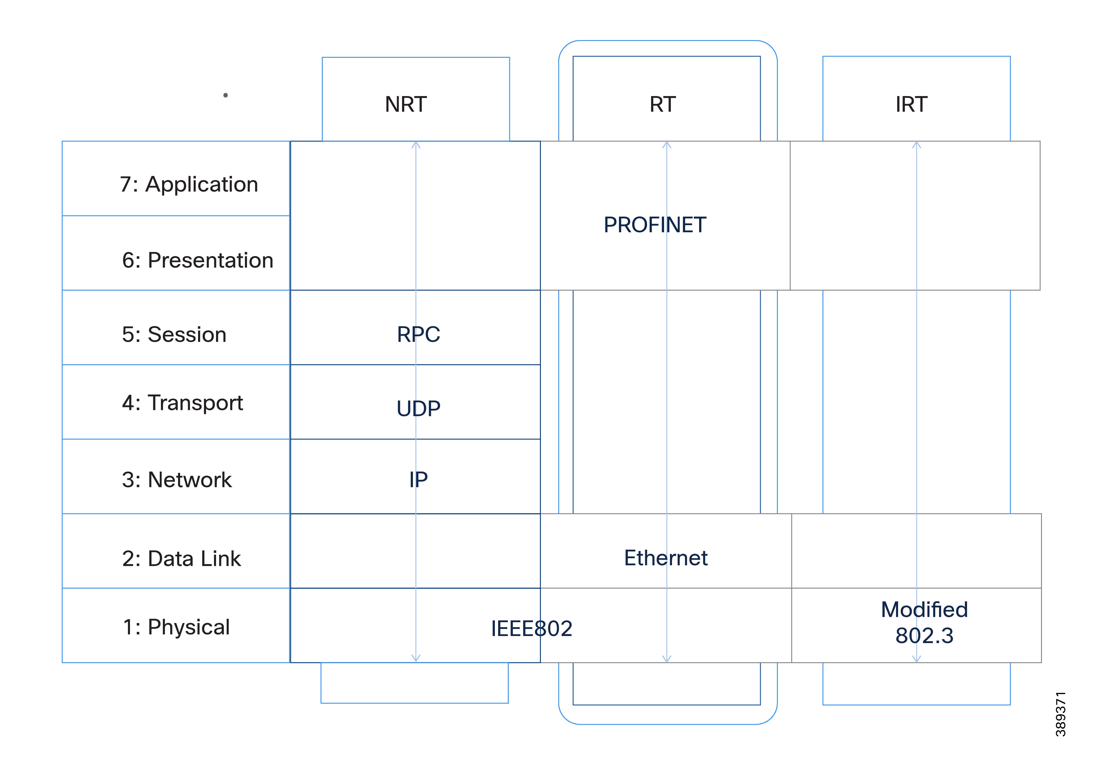
Additionally, PROFINET DCP (Discovery and Configuration Protocol) uses multicast Layer 2 frames to identify and assign device parameters during startup and maintenance operations.
These characteristics impose several constraints on the network:
● Layer 2 adjacency must be preserved between controllers and field devices
● Multicast traffic must be supported for discovery and commissioning workflows
● Short communication interruptions during network reconvergence may not be tolerated by real-time traffic
Traditional enterprise and data center networks are designed around Layer 3 boundaries, routing segmentation, and IP subnet isolation, and do not natively support extending Layer 2 domains across large physical areas or between factory floors and centralized compute environments.
These protocol characteristics are a key driver for the architectural choices described in this CVD.
Traffic Model for Manufacturing Applications
Modern manufacturing networks support a diverse set of applications with very different performance, availability, and fault-tolerance requirements. Virtualized PLCs are one of these applications, but they coexist with HMIs, supervisory systems, data integration platforms, analytics pipelines, and edge and cloud services.
Unlike traditional enterprise applications, many manufacturing workloads are sensitive not only to packet loss, but also to latency, jitter, and packet reordering. Some applications require bounded latency and jitter behavior under all conditions, while others prioritize scalability or data throughput.
As a result, the dual fabric architecture must be designed around application requirements, in addition to devices or bandwidth utilization.
This section defines the primary traffic classes commonly observed in manufacturing environments that include vPLC workloads. The traffic classes described here are representative, not exhaustive, and are intended to provide a structured framework that can be extended while preserving determinism, fault isolation, and operational clarity.
Traffic Classes
The following traffic classes typically appear in manufacturing networks supporting virtualized control and application workloads:
Table 1. Manufacturing Traffic Classes and Design Priorities
| Traffic Class |
Purpose |
Key Characteristics |
Priority |
| Real-Time Control Traffic |
Closed-loop control between control applications (e.g., vPLCs) and field devices or distributed I/O. |
Deterministic, cyclic, extremely sensitive to latency and jitter; tolerates zero packet loss. |
Highest |
| Non-Cyclic Control and Event Traffic |
Acyclic control exchanges, diagnostics, alarms, and state changes. |
Time-sensitive and bursty; more tolerant than real-time control. |
High |
| Engineering and Maintenance Traffic |
Engineering stations, configuration tools, firmware updates, and commissioning activities. |
Bursty and non-deterministic; operationally important but not time-critical. |
Medium |
| Supervisory and HMI Traffic |
Operator commands, HMI updates, visualization, and status polling. |
Latency-sensitive but tolerant of brief delays; often involves high east–west volume. |
Medium |
| Application and Integration Traffic |
Manufacturing Execution Systems (MES), analytics, and edge processing using Message Queuing Telemetry Transport (MQTT), Open Platform Communications Unified Architecture (OPC UA), Representational State Transfer (REST) APIs, and similar protocols. |
Throughput-oriented; tolerant of higher latency and occasional packet loss. |
Low |
| Monitoring and Visibility Traffic |
Asset discovery, telemetry, and Cisco Cyber Vision metadata. |
Passive and non-intrusive; does not impact forwarding behavior. |
Low |
| Management and Orchestration Traffic |
Virtualization management, Cisco Catalyst Center operations, logging, and lifecycle management. |
IT-owned and non-deterministic; explicitly deprioritized. |
Lowest |
The dual fabric architecture defined in this CVD is driven by the following goals:
● Preserve low latency and jitter for cyclic I/O behavior under normal and failure conditions
● Eliminate single points of failure in the network path for critical applications
● Maintain predictable, bounded failover behavior
● Enable security and visibility without impacting control traffic
● Enable structured OT/IT collaboration
Dual SD-Access Fabric Architecture Overview
The following sections provide an overview of the Dual SD-Access Fabric architecture and the design principles that underpin it. It introduces the use of two independent SD-Access fabrics to achieve fault isolation and deterministic behavior for industrial workloads, and sets the context for why SD-Access is the logical foundation for a dual-fabric manufacturing network.
Why Dual Fabric Starts with SD-Access
The dual-fabric architecture described in this CVD is based on two fully independent SD-Access fabrics. These fabrics operate as two separate networks, not as redundant components within a single fabric.
SD-Access uses VXLAN encapsulation to decouple Layer-2 connectivity from physical topology. This capability fundamentally changes how industrial networks can be designed and operated, especially when supporting virtualized workloads such as vPLCs.
In traditional manufacturing networks, physical topology dictates logical design. If two devices, for example a PLC and an I/O device, must reside in the same subnet, they must also be physically connected within the same VLAN domain. Extending that VLAN across the plant floor often results in a large flat network, a complex spanning-tree design, and tightly coupled failure domains.
SD-Access removes this constrain by introducing VXLAN. With VXLAN, Layer-2 connectivity is extended over a routed network, making devices appear physically close even when they are deployed in different locations across the plant. Logical adjacency is preserved without requiring a contiguous Layer-2 domain across the factory floor.
In practical terms, this means:
● A PLC and its associated I/O devices can share the same subnet regardless of physical location
● VLAN membership becomes a logical construct rather than a wiring requirement
● Physical rewiring is no longer required when systems are redesigned or relocated
In essence, the application defines the connection requirement between devices, and the network facilitates that connection.
If a set of PLCs, I/O devices, and HMIs belong to same VLAN, they remain a coherent logical group even when distributed across different production areas. SD-Access provides this flexibility while maintaining segmentation and control, without creating large flat networks.
This capability forms the foundation for modern manufacturing architectures, enabling virtualization, workload mobility, and system redesign without continuous physical network changes. However, this flexibility alone does not eliminate the effects of convergence.
Creating Dual SD-Access Fabrics for Critical Applications
Dual fabric refers to the deployment of two completely independent SD-Access fabrics, each operating as a standalone network.
There are no shared links, no shared control protocols, and no shared forwarding state between the two fabrics. From a network perspective, Fabric A and Fabric B behave as two separate networks.
A single SD-Access fabric already provides resiliency through ECMP and fast convergence, but it still represents one convergence domain. When a link or node failure occurs, traffic using the affected path experiences a brief interruption while the fabric reconverges. For many applications, this behavior is acceptable. For certain industrial workloads, it is not.
To overcome this, the architecture introduces traffic duplication across two independent SD-Access fabrics, ensuring that a failure or convergence event in one fabric has no impact on traffic carried by the other.
Each SD-Access fabric includes:
● Its own physical switching infrastructure
● Its own control plane (IS-IS, LISP)
● Its own forwarding plane (VXLAN)
● Its own failure domain
● Shared Management plane in Cisco Catalyst Center
As illustrated in the diagram, the architecture is composed of two independent SD-Access fabrics, each operating as an isolated fault domain to prevent failures or convergence events in one fabric from affecting the other.
In a Dual SD-Access Fabric architecture, both fabrics operate simultaneously and independently, providing parallel active paths for application traffic. While some applications require uninterrupted communication, using both fabrics introduces additional operational complexity and overhead. For this reason, traffic should use both fabrics only when application requirements demand zero tolerance to packet loss or interruption. Traffic duplication is therefore driven by each application’s tolerance to loss, interruption, and recovery time.
Traffic duplication therefore needs to be driven by application tolerance to loss and interruption:
● Applications that can tolerate brief interruption may use only one fabric.
● Applications that cannot tolerate packet loss or interruption should leverage both fabrics simultaneously, transmitting traffic in parallel across both the fabrics.
Each traffic class must be evaluated to determine whether the application requires near zero-loss resiliency or can tolerate brief service disruptions. The table below provides a decision aid to guide traffic duplication across one or both SD-Access fabrics based on these requirements.
Table 2. Traffic Duplication Across Dual SD-Access Fabrics
| Application Requirement |
Typical Traffic |
Fabric Usage |
Notes |
| Tolerates brief interruption |
Engineering, diagnostics, non-critical monitoring. |
Use one fabric only |
Brief disruption is acceptable during failures or reconvergence. |
| Sensitive to interruption but tolerant to loss |
Human-Machine Interface (HMI), supervisory control. |
Use one fabric only |
Placement depends on operational risk and recovery expectations. |
| Near zero-tolerance to loss or interruption |
Real-time control, critical virtual Programmable Logic Controller (vPLC) I/O. |
Use both fabrics |
Required for continuous, uninterrupted communication. |
| Throughput-oriented, non-deterministic |
Manufacturing Execution Systems (MES), analytics, Message Queuing Telemetry Transport (MQTT), Open Platform Communications Unified Architecture (OPC UA). |
Use one fabric only |
Traffic is contained and rate-limited. |
Regardless of whether traffic is carried on one fabric or both, all traffic must be consistently classified, prioritized, and mapped to appropriate queues in each SD-Access fabric. Time-sensitive control traffic is isolated and prioritized, while non-deterministic and data-centric workloads are rate-limited and contained. This consistency is critical to ensuring predictable behavior across normal and failure conditions.
Further discussion of QoS mechanisms and policy design is provided later in this document.
The ability to use both fabrics simultaneously for selected traffic classes is enabled through the Parallel Redundancy Protocol (PRP). PRP allows frames to be transmitted over two independent networks at the same time, ensuring uninterrupted communication even in the presence of network failures.
PRP operation and design considerations are discussed later in this document.
Architecture Takeaways for vPLC Workloads
In this architecture:
● SD-Access provides Layer 2 extension over a routed fabric for flexible vPLC placement
● Dual fabrics with PRP provide the redundancy to ensure uninterrupted communication
Together, these elements allow modern SD-Access based dual-fabric deployments to support vPLC workloads requirements for strict availability and determinism.
PRP Fundamentals and Terminology
The Dual SD-Access Fabric architecture described in this CVD relies on duplication mechanism to provide uninterrupted communication for selected traffic classes. In particular, the design leverages the Parallel Redundancy Protocol (PRP). PRP is a Layer 2 redundancy mechanism defined in IEC 62439-3. PRP enables uninterrupted communication by transmitting duplicate Ethernet frames simultaneously over two independent networks.
PRP defines the following key components:
● DAN (Dual Attached Node)
An end device that is connected to two independent networks and transmits duplicate frames on both.
● SAN (Single Attached Node)
An end device that is connected to only one network and does not participate in PRP duplication.
● RedBox (Redundancy Box)
A device that enables an endpoint to participate in PRP by duplicating and terminating frames on their behalf.
● vDAN (Virtual DualAttached Node)
A logical PRP construct created by a RedBox on behalf of a single attached device. The RedBox presents the attached device to the network as if it were a DAN.
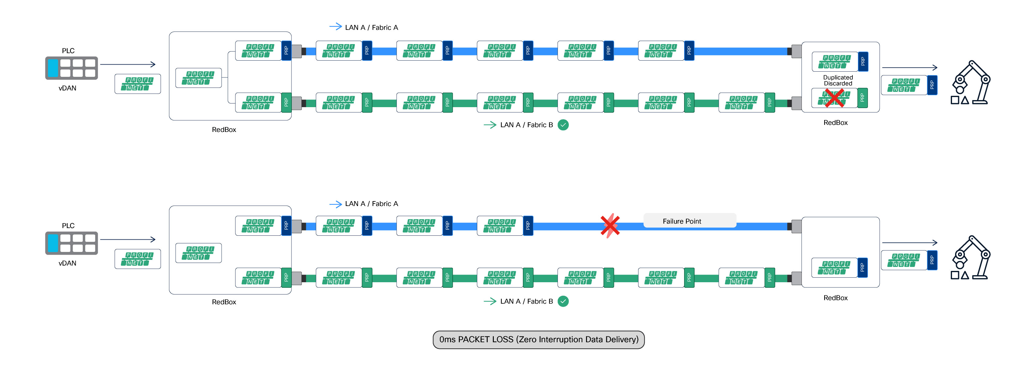
PRP operates entirely at the DANs or RedBoxes. Frames are duplicated and transmitted simultaneously over both independent networks, while the receiving endpoint accepts the first valid frame and discards the duplicate. The network infrastructure remains transparent to PRP operation. The figure below illustrates the concept.
As shown in figure below, frames are duplicated by the sending RedBox and transmitted simultaneously over both LAN A (Fabric A) and LAN B (Fabric B). Upon reception, the receiving RedBox accepts the first valid frame and discards the duplicate. In the event of a failure on one fabric, communication continues without packet loss or interruption, as PRP duplication and de-duplication are handled by RedBoxes at the network access layer and remain transparent to the SD-Access fabric infrastructure.
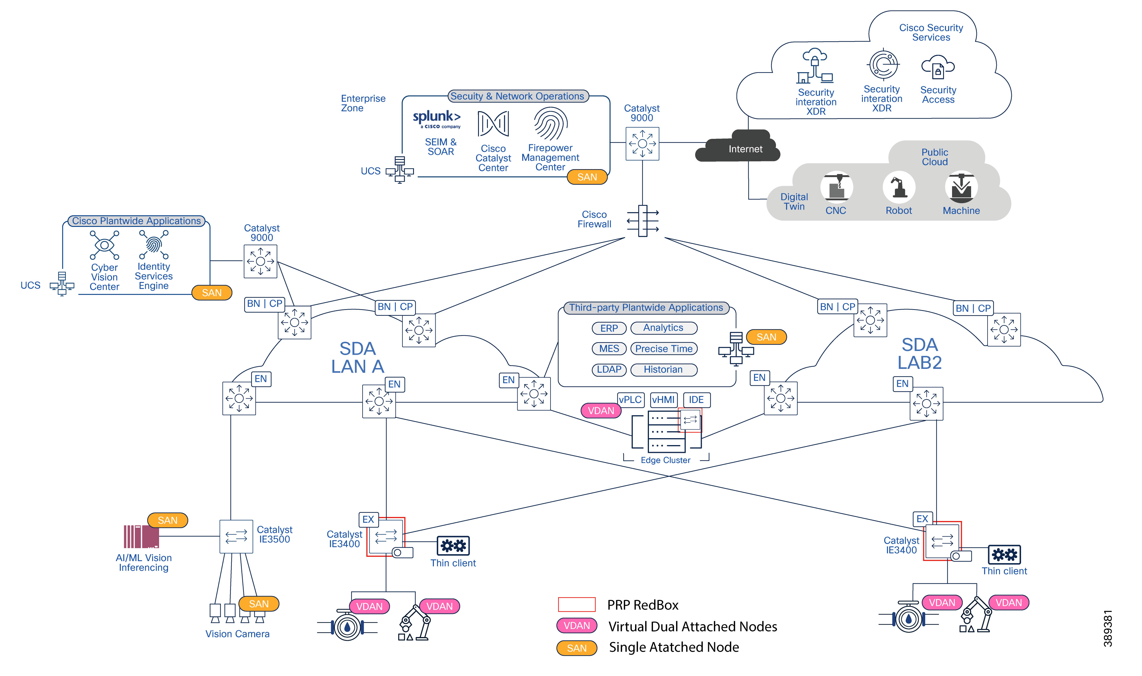
Solution Architecture Components
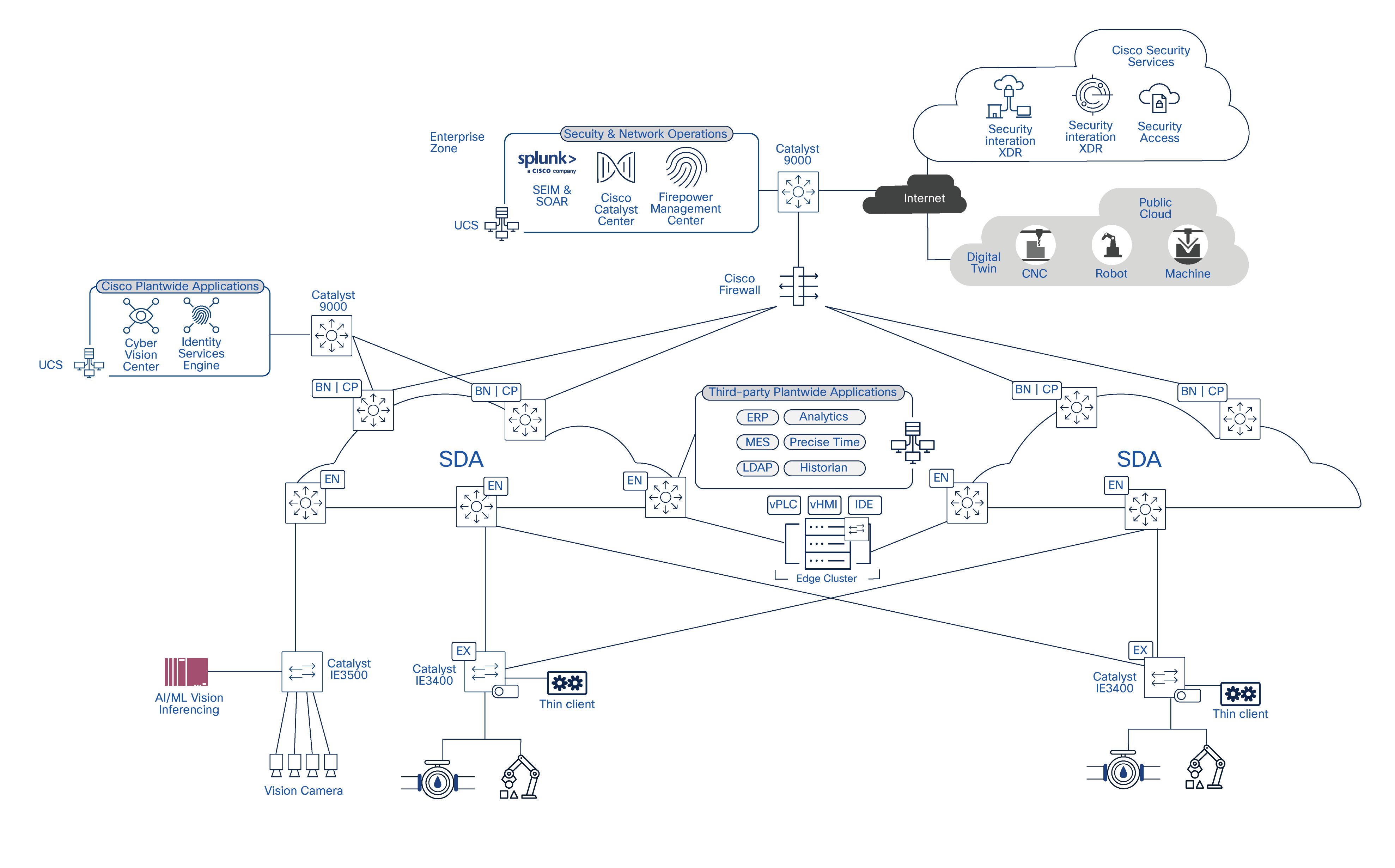
The architecture in this Cisco Validated Design (CVD) extends beyond the network layer. Delivering resilient and predictable virtual Programmable Logic Controller (vPLC) operations requires the coordinated design of multiple layers, each with distinct responsibilities.
Figure 5 illustrates the major architectural components that support vPLC workloads. It highlights the interactions between manufacturing applications, the virtualization layer, and the underlying network infrastructure.
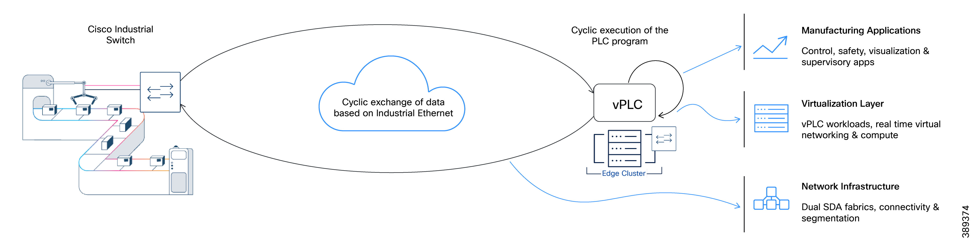
The solution comprises the following architectural components:
● Network Infrastructure: Dual Software-Defined Access (SD-Access) fabrics provide connectivity, segmentation, redundancy, and traffic prioritization from the cell/area zone to the data center.
● Virtualization Layer: The virtualization platform hosts virtual Programmable Logic Controller (vPLC) workloads. It provides the compute, virtual networking, and availability mechanisms that directly influence control application behavior. Unlike traditional enterprise workloads, vPLC performance and availability rely heavily on how the virtualization layer connects workloads to the underlying network.
● Manufacturing Applications: Control, safety, visualization, and supervisory applications impose specific latency, availability, and communication requirements on the underlying infrastructure.
This CVD focuses primarily on the network architecture while explicitly accounting for its interaction with the virtualization platform. The following sections briefly describe the virtualization platform and manufacturing applications before detailing the network architecture.
The Virtualization Layer
This CVD was validated using VMware Cloud Foundation (VCF), Broadcom’s integrated private cloud platform. Only the components that are architecturally relevant to the design described in this document are called out.
Components used in this CVD:
● ESXi (Hypervisor): hosts vPLC virtual machines and other manufacturing workloads.
● vCenter (Virtualization management): provides centralized management and lifecycle operations for the virtual environment. While operationally critical, vCenter is not involved in real-time traffic forwarding.
● NSX (Network and security virtualization): provides the virtual networking framework used to attach vPLC workloads to the factory network in a consistent and repeatable manner.
● Industrial Virtual Switch (IVS): a real-time virtual switch used to connect vPLC workloads to the OT network. IVS is designed to support industrial Ethernet communication patterns, predictable latency characteristics, and resilient connectivity for manufacturing applications. The virtual switch participates in maintaining application connectivity during network or infrastructure events without requiring changes to the control application itself.
● vSAN (Storage virtualization): provides shared, resilient storage for vPLC workloads. vSAN enables workload availability and restart without dependency on local disks, supporting infrastructure-level resiliency while maintaining predictable access to control application state.
Note: Refer to the vendor documentation for specific hardware and software requirements for the compute layer.
Manufacturing Applications in Virtualized Environments
This architecture supports various manufacturing applications increasingly deployed in virtualized environments. These applications impose strict requirements on availability, timing behavior, and operational continuity. You must consider these requirements alongside the underlying infrastructure design.
This section describes the primary application types validated in this CVD and their general operational characteristics. While vendor-specific implementations vary, the architectural requirements remain common across platforms.
Virtualized PLC (vPLC)
A virtualized PLC (vPLC) executes PLC control logic as software running on compute infrastructure, rather than on dedicated controller hardware. The control application executes inside a virtual machine or container and interacts with field devices over Ethernet-based industrial protocols.
Both Siemens and CODESYS provide virtual PLC implementations that are functionally equivalent to a physical PLC, while enabling centralized deployment, lifecycle management, and integration with IT infrastructure.
From an application perspective, vPLCs retain the same real-time communication requirements as physical PLCs, including strict sensitivity to jitter, packet loss, and communication interruptions.
Virtualized Safety PLCs and Timing Requirements
Virtualized safety PLCs execute safety-related logic in software and are designed to meet functional safety requirements up to SIL3, as defined by IEC 61508 and related standards.
In physical safety controllers, timing supervision is typically enforced using dedicated, redundant hardware clocks; to meet SIL3 requirements in virtual PLC environments, a supervised and fault-tolerant external time source is required.
This external time source ensures:
● Supervised time progression
● Detection of time drift, discontinuities, or loss of synchronization
● Fault handling consistent with safety integrity requirements
Vendor implementations address this requirement in different ways:
● CODESYS Virtual Safe Control SL uses a Time Provider VM that distributes supervised time to vPLCs. The Time Provider VM derives time from the ESXi host, which must be synchronized using Network Time Protocol (NTP). The Time Provider VM may serve multiple vPLCs, with a second instance required for redundancy. Time Provider VM must not run on the same host as the associated vPLC to meet safety requirements.
● Siemens SIMATIC S7-1500V with failsafe functions uses a per-host Virtual Time Service that distributes time to virtual controllers running on the same host. The Virtual Time Service requires dedicated, non-integrated network interfaces, implemented as separate PCIe NICs or externally connected IEEE 1588–capable network cards, with a built-in quartz oscillator and configured for PCI passthrough.
While implementation details differ, the architectural requirement is consistent: safety-capable vPLCs depend on an external, supervised, and resilient source of time. This CVD does not cover the configuration of vendor-specific time distribution applications. However, it is important to note that time distribution for safety applications in this design require:
● A dedicated virtual switch instance running on the host
● A dedicated VLAN to distribute time
For network implications and connectivity requirements between the SD-Access fabric and the data center, refer to the Data Center Interconnection section.
Black Channel Principle and SD-Access Fabrics
Safety communication over Ethernet follows the black channel principle (IEC 61508, IEC 61784-3), where the network is treated as an untrusted transport and safety measures are implemented end-to-end by the safety protocol and endpoints. Therefore, safety protocols such as PROFIsafe can operate over SD-Access fabrics provided the network meets the availability and communication performance required by the application.
Human-Machine Interfaces (HMI)
Virtualized HMIs (vHMIs) are supported as part of this architecture. HMI applications may run in the same data center environment as vPLCs or on separate compute resources, depending on operational requirements.
Operator access is typically provided through thin clients, industrial panels, or standard workstations on the factory floor. From an architectural perspective, vHMIs are latency-sensitive but not safety-critical and are treated as supervisory applications rather than control-plane components. While loss of HMI connectivity does not interrupt the control process, it removes operator visibility and interaction capabilities; therefore, resiliency requirements for HMIs must be evaluated based on operational risk and recovery expectations.
Engineering and Commissioning Applications
Engineering and commissioning tools are essential for development, maintenance, and lifecycle operations. These applications are typically deployed as:
● Centralized engineering workstations
● Virtual desktops or dedicated VMs in the data center
Examples include:
● CODESYS IDE
● Siemens TIA Portal
● Associated license servers and engineering services
These applications generate bursty, non-deterministic traffic and are operationally important, but do not participate in real-time control loops. Their requirements influence access, segmentation, and prioritization decisions, but they do not dictate the deterministic behavior of the network.
A Note on Motion Control
High-precision motion control and time-synchronized motion applications over SD-Access fall outside the scope of this CVD.
Validated Hardware and Software
The following tables summarize the hardware platforms and software versions used to validate the dual SD-Access fabric architecture for vPLC workloads, industrial protocols (e.g., PROFINET), and associated OT visibility and security components.
Table 3. Network Infrastructure (SD-Access and Industrial Network)
| Function |
Platform / Component |
Validated Version |
Notes |
| SD-Access fabric edge |
Catalyst 9300 Series and Catalyst 9500 Series |
IOS-XE 17.15 |
SD-Access fabric edge; PRP transport termination point |
| SD-Access fabric control & border |
Catalyst 9500 Series |
IOS-XE 17.15 |
SD-Access control-plane and border roles |
| Industrial Access |
Cisco Catalyst IE3400 Series |
IOS-XE 17.18.2 |
Policy extended node; supports PRP. |
| Network controller |
Cisco Catalyst Center |
3.1.6 |
Central provisioning, assurance, and lifecycle management |
| Policy & Segmentation |
Cisco Identity Services Engine (ISE) |
|
Central policy server for segmentation |
| OT Visibility |
Cisco Cyber Vision |
5.3.3 |
Embedded sensors and centralized OT visibility |
| Secure Remote Access |
Cisco Secure Equipment Access (SEA) |
Latest supported |
Deployment validated with SD-Access workflows |
Table 4. Virtualization layer
| Function |
Platform / Component |
Validated Version |
Notes |
| Virtualization Management |
VMware vCenter |
9.0 |
Centralized virtualization management |
| Virtual Switching |
VMware NSX (IVS) |
9.0 |
Virtual industrial switch for dual-fabric connectivity |
| Hypervisor |
VMware ESXi |
9.0 |
Hypervisor for vPLC and supporting workloads |
Table 5. Manufacturing Applications – Siemens Stack
| Component |
Role in Architecture |
Validated Version |
Notes |
| TIA Portal |
Engineering and configuration environment |
V20 Update 1 |
Used for PLC, safety, HMI, and device configuration |
| Industrial Edge Management (IEM) |
Centralized lifecycle and application management |
1.15.9 |
Management plane for Industrial Edge components |
| Industrial Edge Device Virtualization (IEDV) |
Virtualized runtime for industrial applications |
1.24.2-1 |
Hosts Siemens industrial workloads |
| Virtual PLC (S7-1500V) |
Execution of control logic in a virtualized environment |
V 2.1.0+09 |
vPLC workload |
| Safety PLC (S7-1500 Virtual Controller CPU 1517V(F) ) |
Execution of safety-related control logic |
V 2.2.0+03 |
SIL-capable safety functions |
| Virtual Time Service |
Supervised time distribution for safety applications |
V 1.0.0 |
Provides supervised time to failsafe vPLCs |
| Industrial Edge Hub |
Data aggregation and integration services |
NA |
Data handling and integration layer |
| WinCC Unified (vHMI) |
Virtualized HMI and operator interface |
V4.0.0 (WinCC Unified 6.0.0.20 - TIA V20 UP2) |
Operator visualization and control |
Table 6. Manufacturing Applications – CODESYS Stack
| Component |
Role in Architecture |
Validated Version |
Notes |
| CODESYS IDE |
Engineering and programming environment |
V3.5 SP21 Patch3 |
PLC and safety application development |
| CODESYS Virtual Control for Linux SL |
Execution of control logic in a virtualized environment |
4.18.0.0 |
vPLC workload |
| CODESYS Virtual Safe Control SL |
Execution of safety-related control logic |
4.18.0.0 |
Safety-capable control runtime |
| CODESYS Virtual Safe Timeprovider SL |
Supervised time distribution for safety-capable vPLCs |
4.18.0.0 |
Provides time services to Control Safe |
| License Management |
Licensing services for virtual controllers |
4.18.0.0 |
Centralized license handling |
Table 7. Test, Validation, and Operator Tools
| Tool / Component |
Role in Validation |
Version |
Notes |
| IXIA IxNetwork |
Traffic generation and scale testing |
N/A |
Used for congestion, failure, and QoS validation |
| EKS InTec FS::BOX |
PROFINET scale and endurance testing |
N/A |
Industrial traffic stress and longevity tests |
| Thin Client running IGEL OS |
Operator and HMI access |
IGEL OS 11 |
Used for operator interaction and validation |
Dual SD-Access Fabric Networking Design
As explained in previous section, each SD-Access fabric operates as a complete, independent SD-Access domain, supporting the full set of functions required to deliver connectivity from the cell/area zone to the data center.
Each fabric independently includes:
● Industrial Ethernet switches providing connectivity to PLCs, I/O devices, HMIs, and cell/area zone equipment
● SD-Access edge nodes responsible for endpoint attachment and VXLAN encapsulation
● SD-Access control plane nodes providing endpoint-to-location mapping and fabric control functions
● SD-Access border nodes providing connectivity between the fabric and external networks, including the data center
These roles are implemented per fabric, as described in the Cisco SD-Access design guide, and are not shared between fabrics. Each fabric maintains its own control, forwarding, and policy enforcement domains. This design doesn’t cover design and best practices for SD-Access architecture. Refer Cisco Software-Defined Access Solution Design Guide for more information.
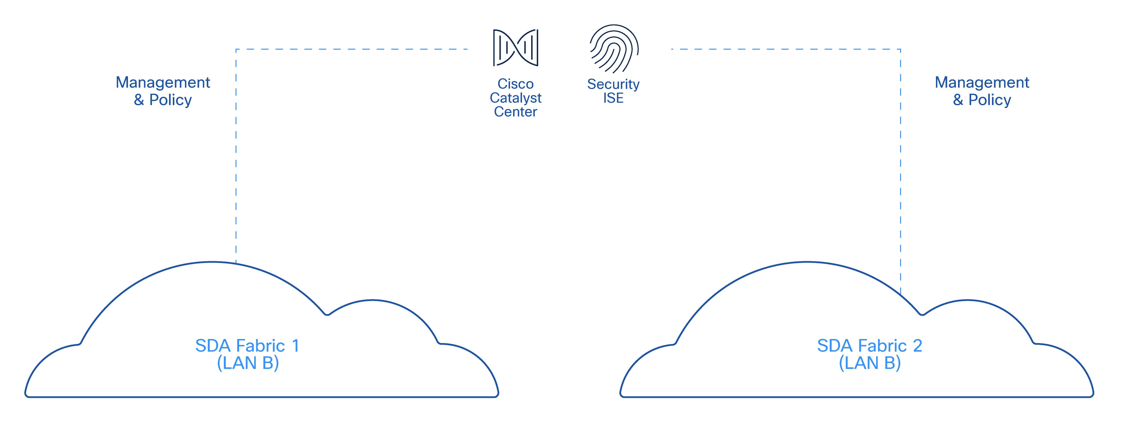
Management and Policy Plane Considerations
While the two fabrics are independent from a forwarding and control-plane perspective, they are operated under a shared management and policy framework.
● Catalyst Center is used to design, provision, and monitor both SD-Access fabrics
● A single Cisco ISE deployment provides centralized identity, authentication, and policy services
This shared management and policy plane simplifies operations and ensures consistent security posture across both fabrics. These shared components do not introduce shared forwarding dependencies. Loss of a management or policy service must not impact ongoing data-plane traffic in either fabric.
Figure 6 illustrates the shared management and policy plane across independent SD-Access fabrics.
vPLC architectures place critical manufacturing workloads in the data center, making data center connectivity a foundational dependency. The interconnection design must therefore provide high availability, predictable behavior, and support for maintenance activities without impacting production.
The data center interconnection is implemented using a fabric edge virtual switch stack to provide redundant physical connectivity and support in-service software upgrades. This allows maintenance activities to be performed without disrupting availability of virtualized workloads, including vPLCs and safety-related services.
This capability is essential in manufacturing environments where centralized compute resources must remain available during planned maintenance windows.
Figure 7 displays the connections between the server and the fabrics. The following section explains this connectivity.
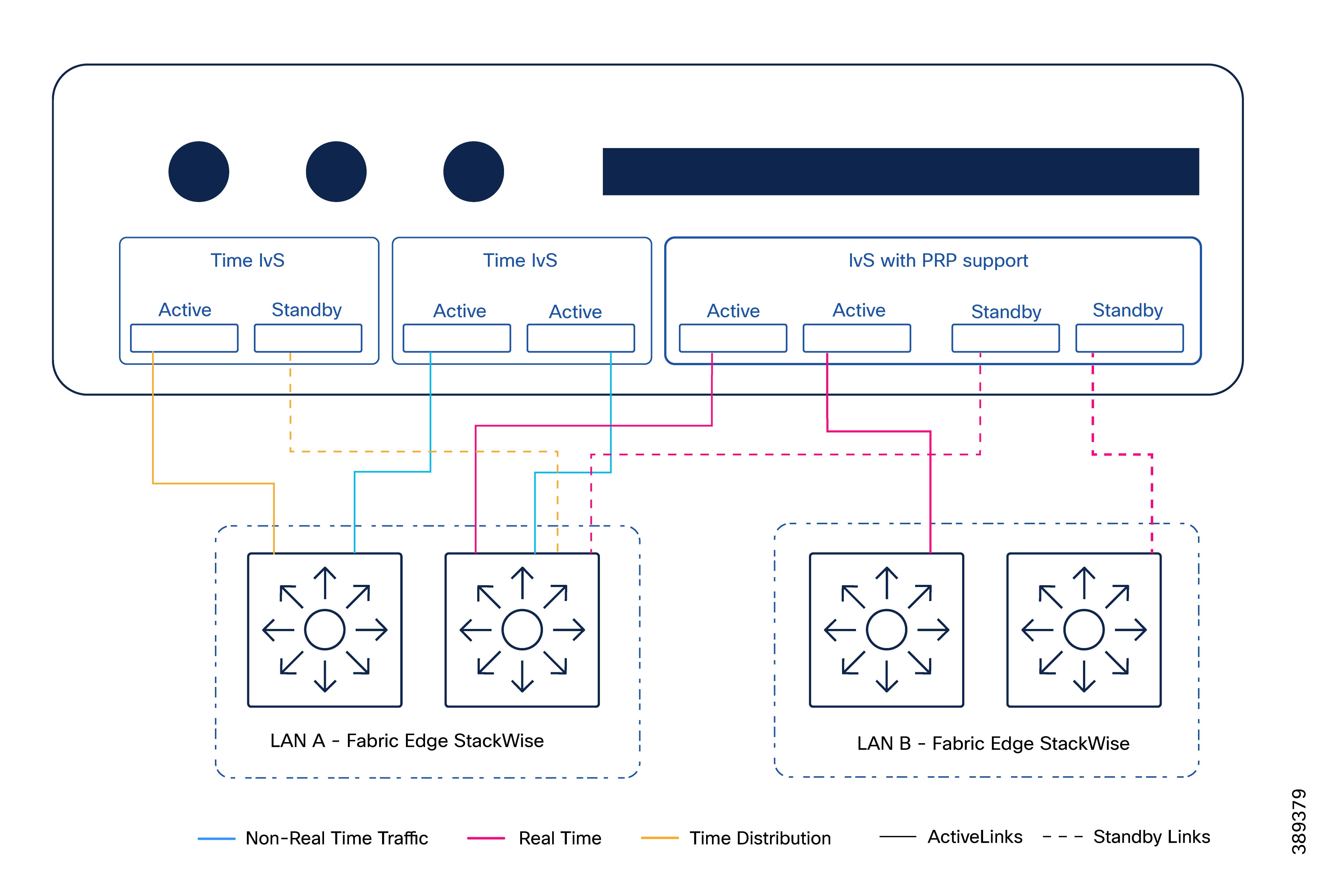
Real-Time Traffic Connectivity to Dual Fabrics
The data center connects to both SD-Access fabrics to support real-time and safety-related traffic, depicted in pink in the diagram and terminating in the IvS.
The following list summarizes the connectivity characteristics:
● Each fabric provides one or more physical links to the data center.
● These links act as uplinks for the industrial virtual switch operating as a RedBox, providing connectivity to both fabrics.
● Interfaces are configured as Layer 2 trunks.
● Dual links to same fabric operate in an active/standby mode.
● Forwarding behavior is controlled by the virtual switching layer, not by the SD-Access fabrics.
This design allows real-time traffic to be transported over both fabrics while preserving complete fabric isolation and avoiding shared failure domains.
Non-Real-Time Traffic Handling
Non-real-time traffic is intentionally constrained to a single fabric (LAN A). This is depicted in blue in the connectivity diagram.
This includes virtualization platform management traffic, storage traffic, non-real-time application VLANs and overlays.
The following list summarizes the connectivity characteristics:
● Hosts connect only to LAN A for non-real-time services.
● Dual uplink per host is recommended for resiliency.
● Fabric edge interfaces toward the hosts are configured as Layer 2 trunks.
This separation reduces operational complexity and ensures that non-critical traffic does not interfere with real-time communication paths.
Time Distribution Connectivity for Safety PLCs
In some implementations (for example, CODESYS-based safety PLC deployments), time distribution for safety applications requires a dedicated network path. This is depicted in orange in the connectivity diagram.
The following list summarizes the connectivity characteristics:
● Time distribution traffic is switched only on LAN A fabric edge node.
● A dedicated VLAN is created on the fabric edge to transport this traffic.
● Flooding is not required, as time traffic remains local to the data center fabric edge.
● Given the nature of time-distribution packets, PTP must not be enabled on the fabric edge for this VLAN.
● When high utilization is expected across stack members, consider marking time distribution traffic with an appropriate Differentiated Services Code Point (DSCP) value to enable prioritization over less time-sensitive workloads (e.g., VSAN). This behavior is not validated in this CVD. Refer to Cisco guidance on QoS for Catalyst 9000 stack architectures. https://www.cisco.com/c/en/us/products/collateral/switches/catalyst-9000/nb-06-cat-9k-stack-wp-cte-en.html#QualityofService
This approach supports safety-related timing requirements while minimizing the impact on the SD-Access fabric.
Note: In architectures where time distribution is delivered over the network, PRP does not provide resiliency for timing. If the connectivity to the fabric edge node responsible for forwarding time traffic fails, time distribution between the time source and the safety PLC may be disrupted. This highlights an important design consideration when time distribution depends on network connectivity. Architectural enhancements should be explored to improve resiliency against network failures between the time distribution application and the fabric edge.
At the cell/area zone level:
● An industrial Ethernet switch with PRP support (for example, IE3400) is deployed
● The switch is connected to both SD-Access fabrics simultaneously
● PRP is used to duplicate critical traffic toward both fabrics
This design ensures that loss of a single fabric, uplink, or intermediate node does not interrupt communication between the vPLC and field devices.
Summary of Architectural Characteristics
The architectural scope of the dual SD-Access fabric design can be summarized as follows:
● Each fabric is a complete SD-Access deployment with its own edge, control, and border nodes
● Management and policy services are centralized
● Both the data center and the cell/area zone are dual-connected using PRP-capable components
● Fabric independence is preserved end-to-end, from the factory floor to the data center
This design ensures that the dual fabric architecture delivers both the flexibility of SD-Access and the determinism required by industrial control systems.
PRP Operation Across Dual SD-Access Fabrics
In this architecture, PRP is used to protect application traffic that cannot tolerate packet loss or interruption, independent of network convergence behavior.
The dual SD-Access fabric design provides the two independent networks required by PRP:
● Fabric A (LAN A)
● Fabric B (LAN B)
Each PRP-protected frame is transmitted simultaneously across both fabrics. The receiving RedBox processes the first valid frame and discards the duplicate.
PRP frame duplication occurs only when required, based on the knowledge of the PRP-capable device performing duplication, typically a RedBox. This decision is driven by the PRP node table maintained by that device. Entries for DANs and vDANs are populated through PRP supervisory frames exchanged between PRP-capable devices, while SANs are learned through normal data-plane traffic. Based on this information, duplication follows these rules:
● Frames destined to DANs are duplicated (for example, dual-attached I/O devices that natively support PRP).
● Frames destined to vDANs are duplicated (for example, endpoints presented as PRP-capable through a RedBox).
● Frames destined to unknown MAC addresses are duplicated during address learning or startup conditions.
● Frames destined to SANs are not duplicated (for example, endpoints connected to a single network only).
This behavior allows PRP to protect only traffic flows that require zero interruption, while avoiding unnecessary duplication of non-critical traffic.
Figure 8 maps the PRP duplication rules described in the previous section to the manufacturing example, highlighting how traffic is treated.
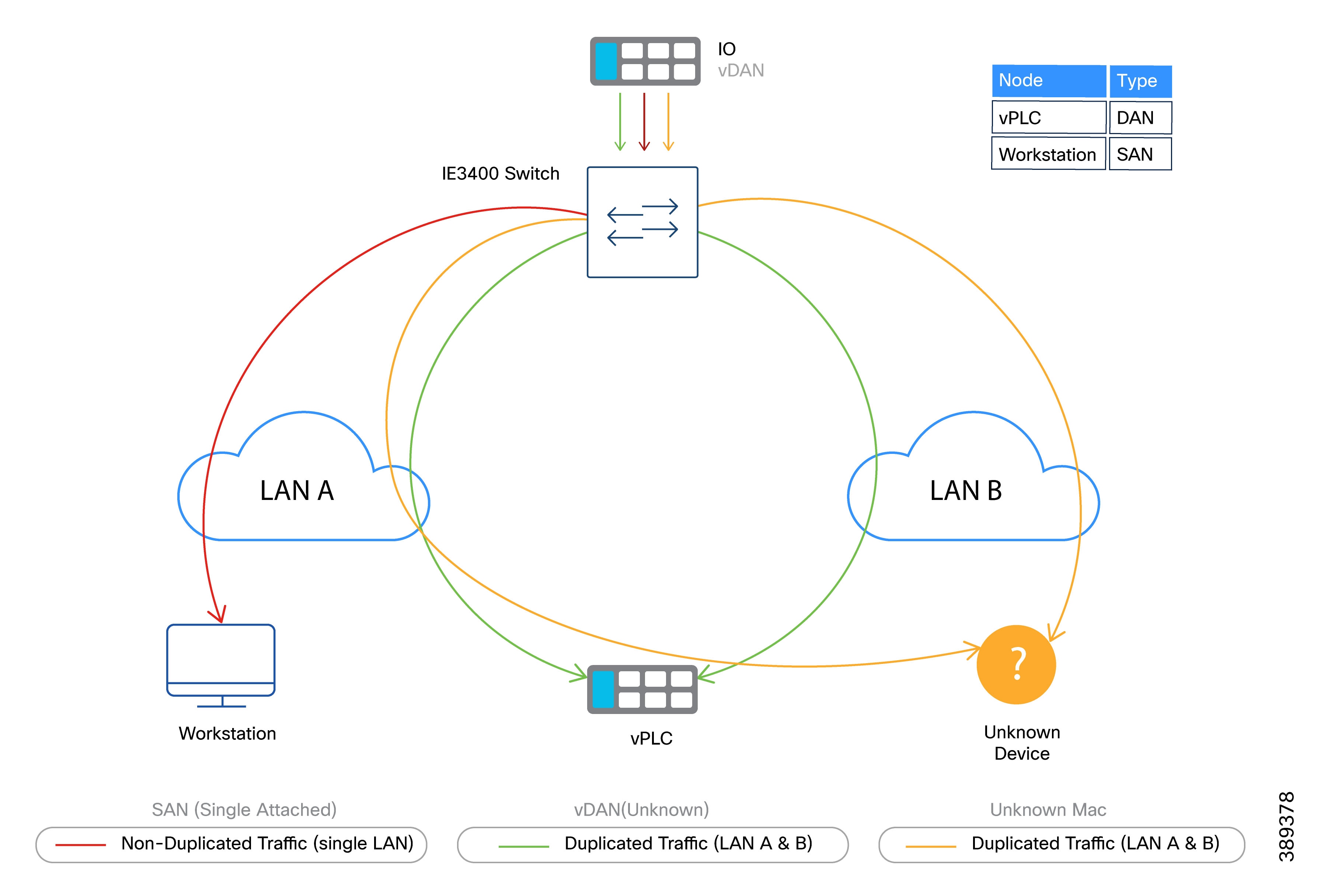
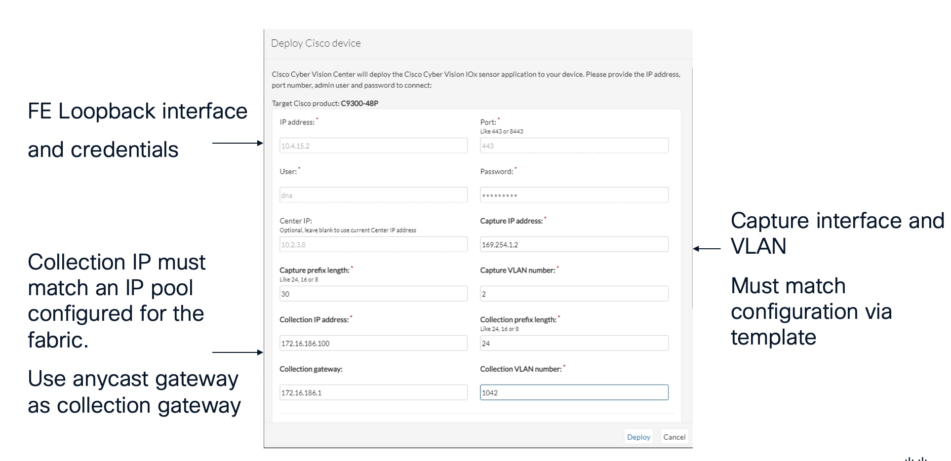
Consider a manufacturing cell where a vPLC with a PROFINET interface is connected behind a virtual RedBox, and distributed I/O devices are connected through a Catalyst IE3400 switch with PRP support. The PROFINET VLAN is instantiated in both SD-Access fabrics (LAN A and LAN B).
In this scenario, the virtual RedBox presents the vPLC as a vDAN, while the distributed I/O devices are also represented as vDANs, attached through the Catalyst IE3400 acting as a RedBox. PROFINET traffic sent by the I/O devices to the vPLC is duplicated by the Catalyst IE3400 based on its PRP node table, which identifies the vPLC as a DAN. As long as the VLAN is mapped to the same Layer 2 Virtual Network Identifier (L2VNI) in both fabrics and the PRP topology is correctly configured, control traffic is delivered without interruption even if one fabric experiences a failure. This selective duplication model ensures that only critical manufacturing traffic is protected, while other manufacturing and IT traffic continues to rely on standard SD-Access fabric resiliency mechanisms.
In contrast, traffic between the same I/O devices and a diagnostic or engineering workstation connected only to LAN A is not duplicated, as the destination is identified as a single attached node. As a result, the Catalyst IE3400 does not replicate this traffic.
Key Takeaway: PRP duplication is applied selectively based on the destination device and RedBox behavior, not simply by VLAN membership. While the VLAN must be present in both fabrics, frame replication occurs only when the destination is identified as PRP-capable.
PRP RedBox Placement in the Dual SD-Access Fabric Architecture
In this architecture, PRP functionality is implemented exclusively at the network access layer through RedBoxes. The SD-Access fabric itself remains transparent to PRP operation.
PRP RedBoxes are deployed at the following locations:
● Cell/Area Zone: Industrial Ethernet switches with PRP support (i.e. Catalyst IE3400) act as RedBoxes for single attached field devices (for example, I/O, and sensors).
● Data Center / Virtualization Layer: Virtual RedBoxes are used to represent virtualized workloads (such as vPLCs) as PRP-capable endpoints.
In this design, RedBoxes located in the cell/area zone are deployed as Policy Extended Nodes (PENs). As such, they operate strictly as Layer 2 devices and do not participate in SD-Access fabric control-plane or forwarding-plane functions.
PRP functionality is configured after PEN onboarding is completed using a Cisco Catalyst Center workflow. Refer to Catalyst IE3400 Commissioning and Replacement Procedures for more details.
Note: In this design, Policy Extended Nodes are provisioned and managed through only one of the single SD-Access fabric. To simplify operations, PEN management connectivity is provided exclusively via LAN A.
While the PEN maintains Layer 2 connectivity to critical OT VLANs in both fabrics, management and provisioning traffic is not duplicated. As a result, a link failure between the PEN and LAN A may render the device temporarily unreachable from a management perspective; however, critical manufacturing traffic continues to flow uninterrupted across both fabrics. Management access is restored once connectivity to LAN A is re-established.
Layer 2 and Layer 3 connectivity considerations for PENs are discussed in a later section of this document.
The following diagram illustrates the placement of PRP RedBoxes within the dual SD-Access fabric architecture and highlights how different endpoint types are represented from a PRP perspective.
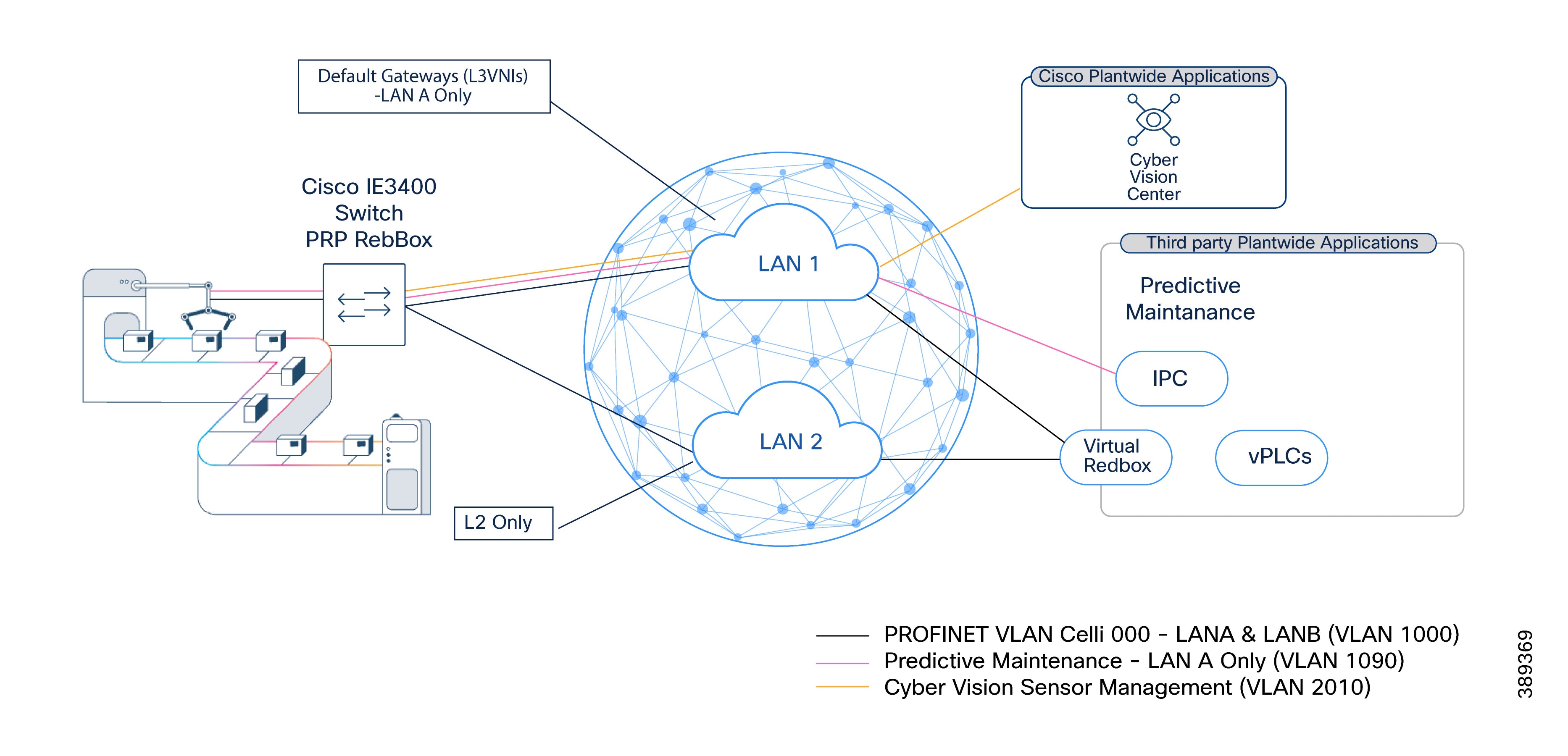
Layer 2 and Layer 3 Boundaries in Dual SD-Access Fabric
PRP in this architecture is intended to protect traffic that remains within the same VLAN. As a result, PRP-protected traffic must remain within a single broadcast domain.
In the dual SD-Access fabric architecture identical L2VNIs are created in both fabrics for traffic that requires PRP protection. For example, a PROFINET VLAN (VLAN 1000) is instantiated as the same L2VNI in Fabric A and Fabric B. This allows PRP duplication to occur across both fabrics while preserving logical adjacency. However, Layer 3 gateways represent a special case.
SD-Access default gateways are implemented on fabric edge nodes, which are SANs from a PRP perspective. As a result:
● A PRP-protected VLAN must have its default gateway in only one fabric
● The corresponding L3VNI is created only in that fabric
For clarity, this document refers to the fabric hosting the default gateway as LAN A.
LAN B carries duplicate Layer 2 traffic but does not host a gateway for that VLAN. Anycast gateways in this architecture are treated as single attached nodes (SANs) from a PRP perspective; deploying a gateway in both fabrics would introduce a PRP-incompatible multi-attached gateway and compromise correct PRP operation.
The following table serves as a reference for LAN A and LAN B configuration.
Table 8. LAN A and LAN B Virtual Network Configuration Reference
| LAN A (Primary Fabric Configuration) |
LAN B (Redundant Fabric Configuration) |
| Layer 3 virtual networks: Create VNs to define macro-segmentation (e.g., OT, IoT, and Management). |
Critical Applications Only (i.e. PROFINET): Create Layer 2 Virtual Networks specifically for critical applications. Non-critical traffic is not required on this fabric. |
| Standard Anycast Gateways: Create gateways for non-critical applications. |
VLAN ID Matching: Ensure VLAN IDs match exactly with those defined in LAN A for the corresponding critical applications. |
| Critical Application Gateways (i.e. PROFINET): Create gateways with Layer 2 flooding enabled to support PRP operation. |
Redundancy note: LAN B mirrors the critical L2 structures of LAN A to ensure seamless PRP (Parallel Redundancy Protocol) operation without duplicating non-essential traffic. |
| Extended Node Gateway: Create in the INFRA_VN to support Policy Extended Node (PEN) management. |
Example: Layer 2 and Layer 3 Boundaries for PRP and Non-PRP VLANs
Table 9 illustrates how VLANs are distributed across LAN A and LAN B in a dual SD-Access fabric architecture, using PROFINET and related manufacturing traffic as examples.
Table 9. Example: Layer 2 and Layer 3 Boundaries for PRP and Non-PRP VLANs
| VLAN ID |
Purpose |
LAN A (Fabric A) |
LAN B (Fabric B) |
VRF (LAN A) |
PRP Usage |
Design Notes |
| 1000–1003 |
PROFINET I/O (Critical Control) |
L2VNI + optional L3VNI (Gateway) |
L2VNI only |
OT VRF (if gateway present) |
Yes |
Identical L2VNIs in both fabrics. Default gateway, if required, exists only in LAN A. L2 flooding enabled in both fabrics for DCP discovery. |
| 1040 |
Infrastructure / Policy Extended Nodes |
L2VNI + L3VNI (Gateway) |
Not present |
Underlay VRF |
No |
Infrastructure VLAN for PEN connectivity. Routed only in LAN A. Not extended to LAN B. |
| 1060 |
OT Application Management |
L2VNI + L3VNI (Gateway) |
Not present |
OT VRF |
No |
Management traffic for OT applications. Routed only in LAN A, same VRF as PROFINET gateways. |
| 1080–1085 |
Data Center Management (vMotion, ESXi, vSAN) |
L2VNI + L3VNI (Gateway) |
Not present |
DC Management VRF |
No |
Virtualization infrastructure traffic. Isolated in its own VRF and confined to LAN A. |
| 1090 |
MQTT / IoT Messaging |
L2VNI + L3VNI (Gateway) |
Not present |
IoT VRF |
No |
Non-real-time IoT traffic. Routed only in LAN A. |
| 2000 |
Vision System Traffic |
L2VNI + L3VNI (Gateway) |
Not present |
OT VRF |
No |
High-bandwidth, non-PRP traffic. Confined to LAN A. |
| 2010 |
Cyber Vision Sensors |
L2VNI + L3VNI (Gateway) |
Not present |
Management VRF |
No |
OT visibility traffic. Exists only in LAN A and isolated in a management VRF. |
Design Rules Reinforced by this example
· PRP-protected VLANs must be instantiated as identical L2VNIs in both LAN A and LAN B.
· A default gateway, if required, must exist in only one fabric, LAN A.
· VLANs that do not require PRP are confined to LAN A and use standard SD-Access L2/L3 behavior.
Figure 10 below illustrates PRP across two independent SD-Access fabrics. PRP VLANs are extended as L2VNIs in both LAN A and LAN B, while default gateways (L3VNIs), when required, exist only in LAN A. Non-PRP services are confined to LAN A to preserve fabric isolation and operational simplicity.
PRP deployments must account for scale and operational behavior, particularly in large manufacturing environments and centralized data center architectures.
PRP Supervisory Frames and Default Behavior
In standard PRP operation, remote DANs and vDANs are learned by RedBoxes through PRP supervisory frames. These PRP supervisory frames are used to discover and maintain information about PRP-capable endpoints and are essential for correct duplication and de-duplication behavior.
By default:
● PRP supervisory frames are sent untagged (native VLAN)
● A RedBox learns any vDAN from any received supervision frame
● Learned vDANs are stored in a node table on the RedBox
This default behavior works well in small, flat Layer 2 deployments. However, it introduces challenges in SD-Access based fabrics and at scale.
Implications in SD-Access Based Fabrics
In SD-Access fabrics, untagged Ethernet frames are not forwarded through the fabric. As a result, default PRP supervisory frames would be dropped unless they are explicitly tagged.
To address this, industrial switches supporting PRP allow configuration of a single VLAN used for PRP supervisory traffic. This ensures that supervisory frames are properly encapsulated and forwarded through the SD-Access fabric.
By default, a RedBox:
● Learns vDANs from all received supervisory frames and SAN from data traffic
● Stores learned endpoints in a node table with finite capacity
In large manufacturing deployments, especially those with many cells and zones and large numbers of vDANs, the number of learned vDANs may exceed the available table entries. This can result in:
● Inability to learn new PRP endpoints
● Unpredictable duplication behavior
For these environments, default PRP behavior may be unsuitable. For this reason PRP supervision VLAN aware mode was introduced as a feature on Catalyst IE3400 switches on IOS-XE 17.16.
PRP supervision VLAN aware mode for Scalable Deployments
PRP supervision VLAN aware mode addresses these limitations by providing tighter control over PRP endpoint learning and duplication scope.
With PRP supervision VLAN aware mode:
● PRP supervisory frames are sent tagged on the data VLAN used by the application
● RedBoxes are explicitly configured to learn vDANs only from specific VLANs
● PRP learning and duplication are effectively scoped per VLAN
This allows the creation of logical “PRP domains”, where only endpoints participating in specified VLANs are learned on RedBoxes.
While “PRP domain” is not a formal IEC term, it is a useful conceptual model to describe VLAN-scoped PRP operation in large environments.
Example: PRP Scale on Centralized Data Center for vPLC
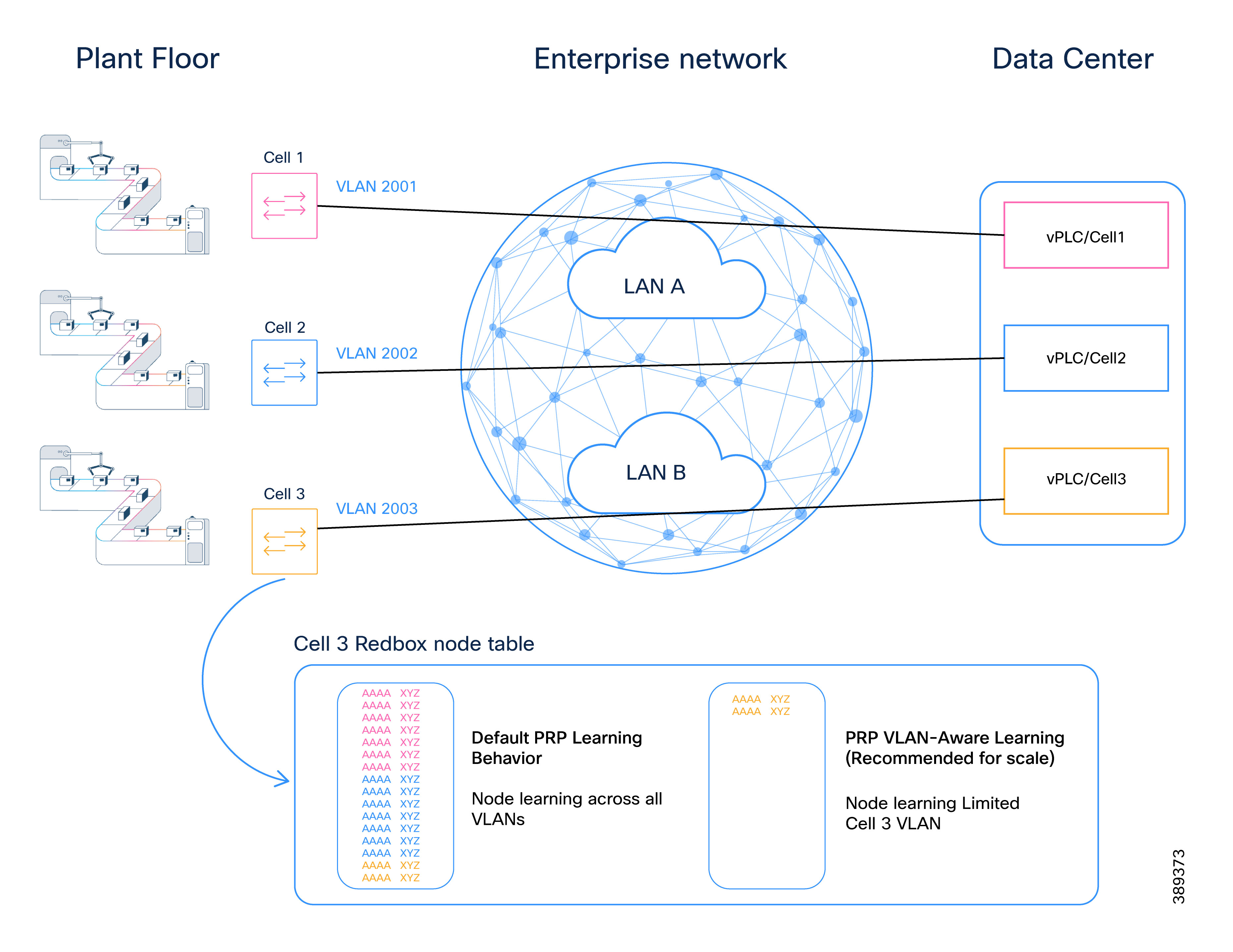
In factories using centralized data centers to host vPLCs or other critical applications, PRP supervision VLAN aware mode becomes particularly important.
Without PRP supervision VLAN aware mode:
● RedBoxes may learn vDANs from unrelated cells or production lines
● Node tables may be exhausted
● Operational isolation between applications is reduced
By scoping PRP learning to specific VLANs:
● PRP scale is controlled
● Application domains remain isolated
● Expansion becomes predictable and manageable
This approach aligns naturally with SD-Access segmentation models and large-scale manufacturing designs.
Operational Guidance for PRP supervision VLAN aware mode Configuration
For scalable and predictable PRP deployments:
● Use PRP supervision VLAN aware mode for scale
● Use VLAN tagging for PRP supervisory frames
● Ensure LAN A and LAN B are created consistently for all PRP-enabled VLANs
● Limit PRP learning to only the VLANs required by the applications in the cell/area zone
● Validate node table utilization during design and expansion phases
Configuration of PRP supervision VLAN aware mode behavior can be automated using Catalyst Center.
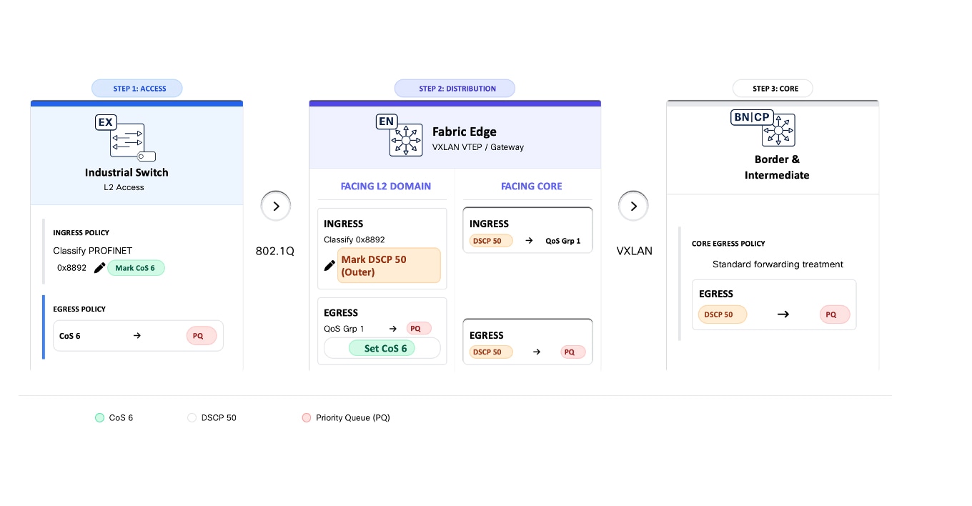
Manufacturing control traffic must receive consistent end-to-end prioritization across the industrial access layer, both SD-Access fabrics, and the data center. Any variation in classification, marking, or queue mapping can introduce delay or jitter that affects control applications.
The QoS design in this CVD ensures that:
● Control traffic is forwarded ahead of all other traffic.
● QoS behavior is consistent across Fabric A and Fabric B.
● VXLAN encapsulation does not remove priority treatment for Layer 2 industrial protocols.
● Priority treatment is preserved from the cell/area zone to the data center and back.
This section uses PROFINET as the industrial ethernet protocol. The same approach applies to other industrial real-time protocols.
Time-Critical Industrial Control Traffic Priority Model
Time-Critical Industrial Control traffic is placed in a strict priority queue on:
● Industrial access switches in the cell/area zone
● SD-Access fabric edge and border nodes
● Any intermediate routed transport carrying the VXLAN underlay
● Data center switching components carrying control traffic
Strict priority queuing ensures that time-critical industrial control traffic is always serviced ahead of other traffic classes. Under congestion, control traffic experiences minimal delay and jitter because lower-priority traffic cannot delay or block it, even when the network is heavily loaded.
The following sections explain how PROFINET RT traffic is identified within the network and prioritized at every hop.
Time-Critical Industrial Control Traffic at the Industrial Access Layer
PROFINET RT traffic is identifiable by EtherType 0x8892 and is commonly marked with Class of Service (CoS) 6. To ensure consistent priority treatment, this design classifies control traffic at ingress rather than relying on endpoint markings.
On industrial access switches:
● Classify control traffic based on EtherType (0x8892).
● Set internal QoS values to map control traffic to the strict priority queue.
● Do not extend trust boundaries beyond the industrial access demarcation.
At this layer, queuing behavior is driven primarily by Layer 2 classification.
Time-Critical Industrial Control Traffic and VXLAN Encapsulation
When traffic enters the SD-Access fabric, it is encapsulated in VXLAN in order to be forwarded on the fabric overlay. For Layer 2 industrial protocols, VXLAN encapsulation introduces an important behavior:
Inside the SD-Access fabric, QoS decisions are made on the encapsulated (outer) headers, so the original Layer 2 markings must be mapped to an outer marking at ingress to preserve priority.
As a result, control traffic must be explicitly prioritized inside the SD-Access fabric using fields visible after encapsulation.
Time-Critical Industrial Control Traffic Handling Inside the SD-Access Fabric
To preserve prioritization across the SD-Access fabric:
● Classify control traffic at the ingress fabric edge, for example by matching EtherType 0x8892 for PROFINET.
● Apply a dedicated DSCP value to the outer IP header of the VXLAN packet, using a non-commonly used value (DSCP 50) to avoid overlap with existing IT traffic classes.
● Ensure all SD-Access nodes map this DSCP value to the strict priority queue. This enables consistent treatment across routed fabric links and removes dependency on original Layer 2 markings.
Restoring Layer 2 Priority for Time-Critical Industrial Control Traffic at Fabric Egress
When traffic exits the SD-Access fabric toward the cell/area zone, VXLAN encapsulation is removed. At the egress fabric edge:
● Map the control traffic DSCP value to a QoS group at the fabric edge before the VXLAN header is removed. This allows the traffic to be correctly identified at the egress interface and remarked with the appropriate Layer 2 marking, for example, CoS 6.
● Ensure this traffic egresses via the strict priority queue.
Summary: End-to-End PROFINET Frame Handling
Figure 12 illustrates how PROFINET real-time control traffic is classified, encapsulated, prioritized, and restored as it traverses from a vPLC in the data center, through an SD-Access fabric, and back into the industrial Layer 2 domain. It highlights how QoS markings are preserved across VXLAN encapsulation to ensure deterministic forwarding behavior for time-sensitive industrial protocols.
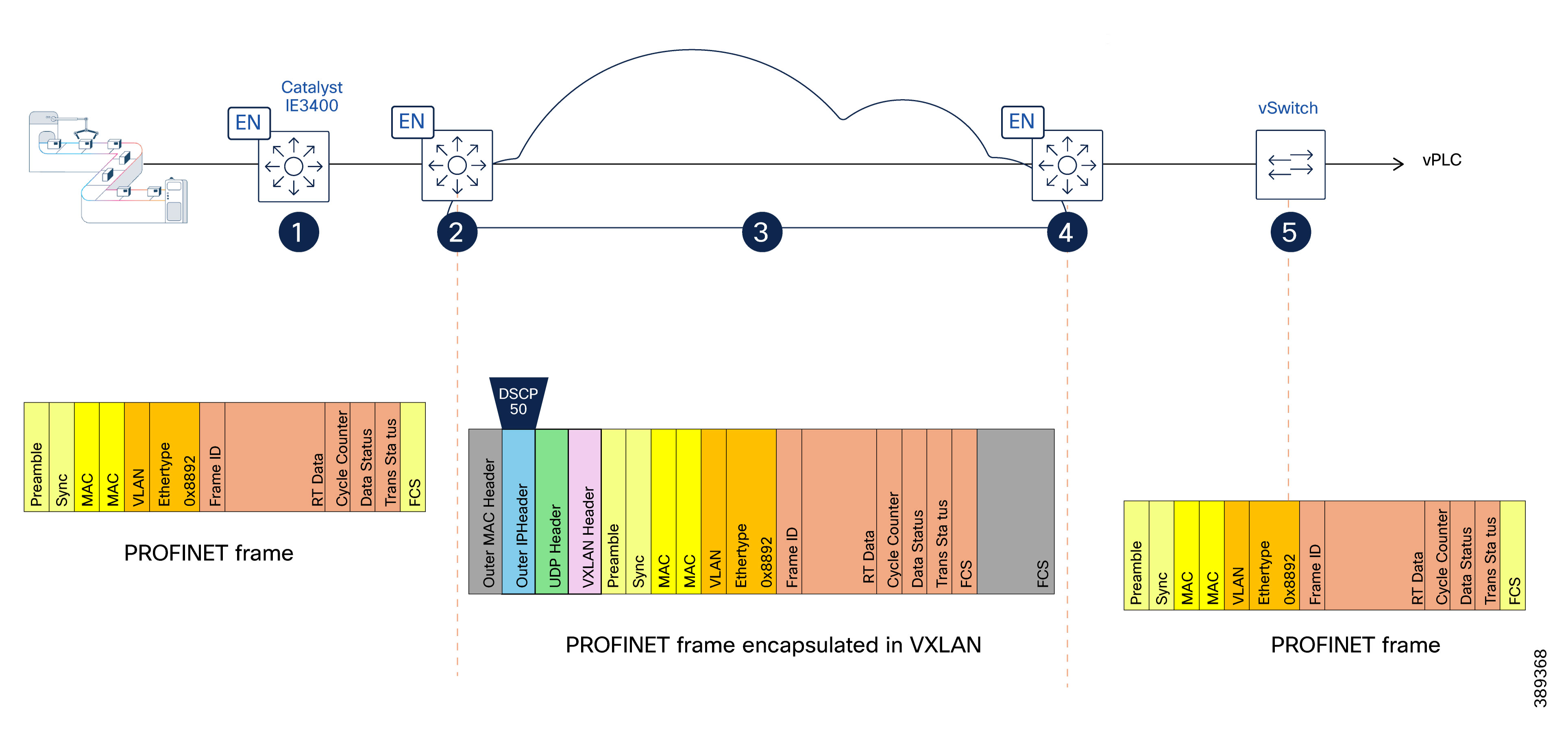
(1) Industrial Access – Native PROFINET Frame
PROFINET real-time control traffic is generated by field devices in the cell/area zone and forwarded by the industrial ethernet switch (Catalyst IE3400).
At this stage, traffic is a native Layer 2 PROFINET frame identified by EtherType 0x8892, with no IP header. The industrial access switch classifies the traffic and places it in the highest-priority queue to ensure preferential forwarding relative to other traffic classes.
(2) SD-Access Fabric Ingress – Classification and VXLAN Encapsulation
At the ingress SD-Access fabric edge, the PROFINET frame is classified based on EtherType (0x8892). The fabric edge encapsulates the Layer 2 frame into VXLAN for transport across the SD-Access fabric. During encapsulation, a dedicated DSCP value (for example, DSCP 50) is applied to the outer IP header to preserve priority treatment within the routed fabric.
(3) Transit Across the SD-Access Fabric – Routed Transport with Preserved Priority
The VXLAN-encapsulated packet traverses the SD-Access fabric using routed underlay links.
Forwarding and queuing decisions inside the fabric are based on the outer IP header. The DSCP marking ensures the packet uses the priority queue at every hop. The result is consistent priority treatment across all fabric nodes, independent of the original Layer 2 frame format.
(4) SD-Access Fabric Egress – Decapsulation and Priority Preservation
At the egress SD-Access fabric edge, VXLAN encapsulation is removed and the original PROFINET Layer 2 frame is restored.
The DSCP derived from the outer VXLAN/IP header is used to map the packet to a QoS group that it is used to put the frame at the appropriate egress queue and assign the Layer 2 priority (COS 6). This guarantees that priority treatment applied inside the fabric is preserved at the layer 2 domain.
(5) Virtual Switch to vPLC – Layer 2 Delivery
The PROFINET frame is delivered to the industrial virtual switch and forwarded to the virtualized PLC (vPLC).
Traffic remains Layer 2 end to end from the application perspective, with priority handling preserved through the network infrastructure.
Consistency Across Both Fabrics
QoS classification, marking, and queue mapping must be identical in Fabric A and Fabric B. Any mismatch (different DSCP values, queue maps, or template variations) can create asymmetric behavior and undermine bounded latency and jitter requirements.
Key QoS Design Principles for Dual SD-Access Fabric Architecture
● Inside the SD-Access fabric, control traffic priority is preserved via DSCP marking on the VXLAN outer header.
● Mapping between Layer 2 and Layer 3 markings must be enforced at fabric ingress and egress.
● Rate limiting and policing apply only to non-critical traffic classes; control traffic is not policed.
QoS policies for classification, marking, queue mapping, and scheduling are deployed using templates to ensure consistency across devices and both fabrics. Detailed configuration examples and validation steps are provided in Appendix - QoS Templates.
The following diagram illustrates the QoS policies applied across the switching infrastructure to preserve PROFINET RT priority end to end. The QoS policies provided align with this model and implement the behavior depicted here.
Layer 2 Flooding and Multicast Requirements
Certain industrial protocols rely on Layer 2 flooding or multicast behavior for device discovery and commissioning. For example, PROFINET uses the Discovery and Configuration Protocol (DCP) to perform device discovery and initial configuration, which requires Layer 2 broadcast communication.
By default, traffic in SD-Access overlays is not flooded, even when Layer 2 is extended. Flooding and multicast behavior must be explicitly enabled where required.
As a result:
● Layer 2 flooding must be enabled for any VLAN used by protocols that rely on broadcast or multicast communication.
● Flooding behavior must be applied consistently across both SD-Access fabrics for the relevant VLANs to ensure predictable operation.
In SD-Access configuration workflows:
● Layer 2 flooding is enabled by default for L2VNIs.
● For L3VNIs, flooding must be explicitly enabled when configuring the Anycast Gateway in Cisco Catalyst Center.
Layer 2 flooding in the overlay is supported by the underlay transport. When multicast-based replication is used, multicast routing must be enabled in the underlay to distribute broadcast, unknown unicast, and multicast (BUM) traffic across the fabric.
This underlay multicast configuration is typically enabled during LAN Automation in Catalyst Center, which provisions the required multicast routing and control-plane parameters as part of fabric bring-up. If multicast was not enabled during LAN Automation, it can later be provisioned using templates.
Failure to enable the appropriate underlay support for flooding may prevent device discovery and commissioning, even when overlay VLANs, VNIs, and policies are correctly defined.
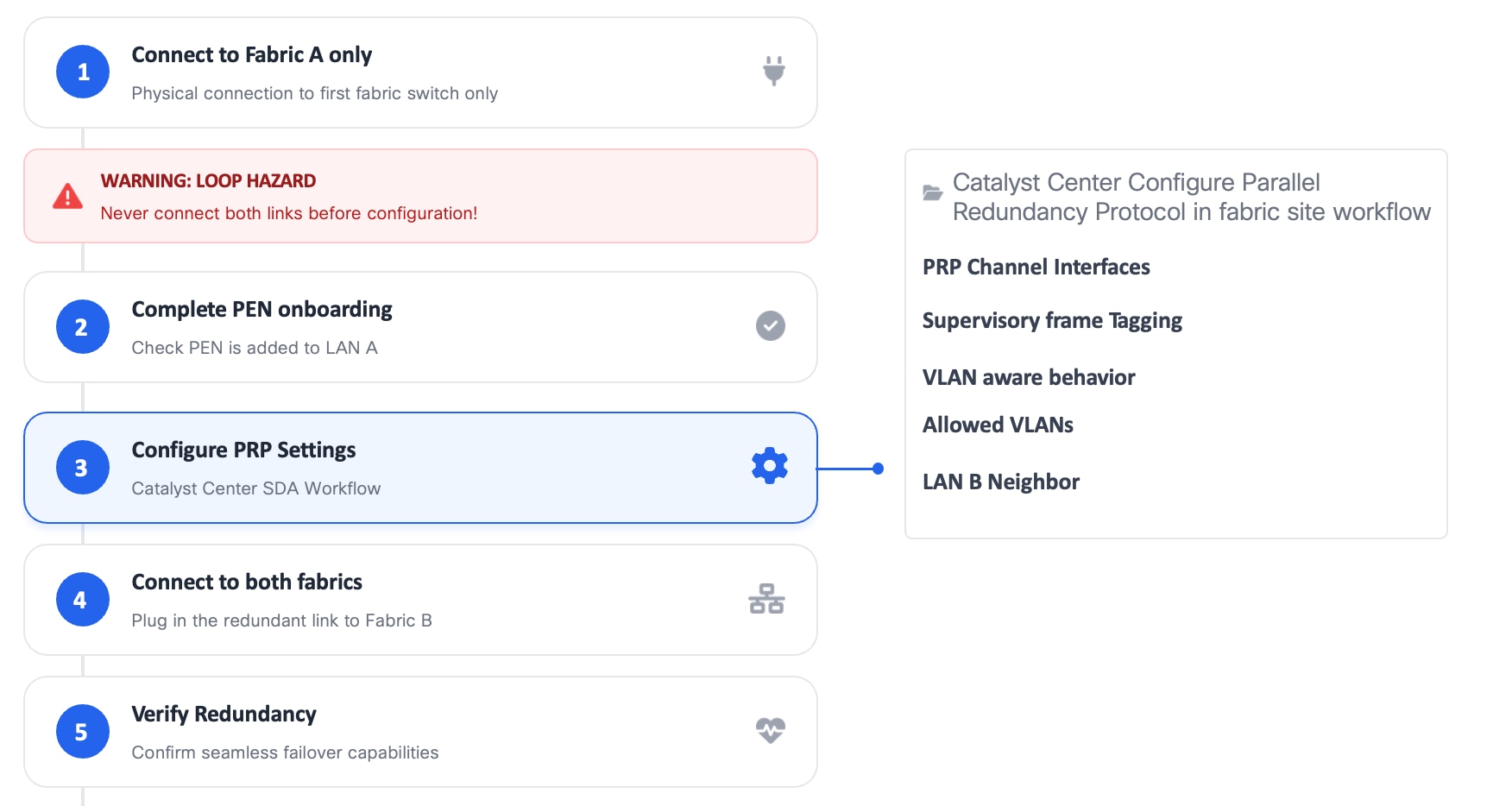
Catalyst IE3400 Commissioning and Replacement Procedures
PRP introduces specific operational requirements during commissioning and maintenance to prevent transient Layer 2 loops and unintended traffic duplication.
In particular:
● Nodes must not be dual-attached to both fabrics before PRP is fully configured.
● Improper sequencing during RedBox onboarding, replacement, or maintenance can temporarily create Layer 2 loops or flooding conditions.
● LAN A, which is used for management, must be the only active attachment until PRP configuration is completed.
To avoid unintended loops:
● RedBoxes must be commissioned using a controlled, step-by-step workflow.
● PRP configuration must be completed before connecting the LAN B interface.
● Replacement workflows must ensure that only the LAN A attachment is active until PRP configuration is verified.
● Onboarding warnings indicating potential loop hazards must be acknowledged and respected.
In SD-Access environments, these requirements are enforced through Cisco Catalyst Center configuration workflows, which guide the operator through:
● Initial onboarding of PEN to Fabric A (LAN A) only
● Completion of PRP configuration, including:
◦ Parallel Redundancy Protocol enablement
◦ PRP channel interfaces
◦ Supervisory frame tagging
◦ VLAN-aware behavior and allowed VLANs
◦ LAN B neighbor definition
● Controlled attachment of the redundant LAN B connection
● Final redundancy and failover verification
These procedures are critical in live manufacturing environments, where improper PRP commissioning or maintenance can affect production traffic beyond the individual RedBox being serviced. Figure below illustrates the commissioning steps.
Operational Considerations for PEN/RedBoxes
Policy Extended Nodes (PENs) enable non-fabric devices to participate in SD-Access policy enforcement. In manufacturing environments, however, their use introduces specific operational and lifecycle considerations that must be carefully evaluated.
At the time this CVD was written, the following constraints apply:
● PEN replacement (RMA) must be performed through Catalyst Center workflows.
● Standalone or locally driven replacement procedures are not supported for PEN devices.
● PEN onboarding, replacement, and recovery therefore depend on Catalyst Center workflows.
In manufacturing environments where rapid replacement and local intervention are common, these dependencies must be explicitly accounted for in operational planning.
When Site-Based Role-Based Access Control (RBAC) is used:
● A PEN inherits the site assignment of its parent fabric edge.
● A PEN cannot be placed in a separate site or zone for more granular permission control.
As a result:
● Permissions applied to the parent fabric edge site implicitly apply to the PEN.
● Fine-grained delegation of access specifically for RedBox devices is not possible.
This behavior is particularly relevant when multiple operational teams, system integrators, or third-party vendors require differentiated access.
Placement of Industrial Ethernet Switches in SD-Access Based Manufacturing Networks
The following guidance applies to industrial switches that are connected to only one fabric. These Industrial Ethernet switches deployed on the manufacturing floor must not assume fabric roles such as fabric edge, Policy Extended Node, or Extended Node. Nevertheless, industrial Ethernet switches can still be managed by Catalyst Center and participate in micro-segmentation policies.
This guidance is driven by operational requirements, safety considerations, and predictable network behavior specific to manufacturing environments, as explained below.
Note that these switches must not forward time-critical industrial control traffic into the fabric, as traffic entering the fabric from a single attachment would not be protected by PRP and could compromise redundancy and availability.
Design Considerations and Operational Constraints
● Deterministic forwarding and fault behavior: industrial control and interlock traffic relies on predictable Layer 2 behavior. Assigning fabric roles to industrial switches introduces dependency on SD-Access forwarding. Even brief convergence events may introduce interruptions that are acceptable in IT networks but visible to time-sensitive manufacturing applications.
● Operational independence and recovery: manufacturing environments require local recovery and commissioning workflows. SD-Access role switches must be provisioned and replaced through Catalyst Center workflows and do not support SD-card–based or fully out-of-band configuration. This limits the ability of OT teams and system integrators to perform local intervention during commissioning or fault scenarios.
● Feature alignment with OT protocols: several OT-specific features are not supported or not validated when industrial switches operate under SD-Access workflows (for example, PROFINET, MRP, CIP-specific behaviors, and Layer 2 NAT). Keeping industrial switches outside the fabric preserves vendor-supported configurations and validated protocol behavior.
● Clear ownership boundaries: fabric devices inherit SD-Access permission models and site-based access control. Industrial switches acting as fabric devices cannot be delegated granular OT-only access, creating unnecessary coupling between IT-managed fabric operations and OT-owned production networks.
Note: As explained earlier, PRP RedBoxes are an exception to this guidance in a dual-fabric architecture. RedBoxes are deployed only as Policy Extended Nodes and are subject to the operational constraints described in the previous section. SD-Access configuration workflows ensure consistent PRP configuration while maintaining predictable failure behavior.
IP Directed Broadcast for Silent Host Use Cases
IP Directed Broadcast in SD-Access allows a routed broadcast packet, addressed to a specific subnet, to be forwarded by the fabric and delivered as a Layer 2 broadcast within the target VLAN. This enables communication with endpoints whose location is not yet known to the fabric, while preserving routing and segmentation boundaries.
In SD-Access, IP directed broadcast is enabled per subnet as part of the Anycast Gateway configuration in Catalyst Center and works in conjunction with Layer 2 flooding to deliver broadcast traffic from the Fabric border to the appropriate fabric edge and VLAN.
IT and OT Collaboration and Shared Infrastructure Considerations
Deploying SD-Access in manufacturing environments is not only a technical decision. It also introduces organizational and operational dependencies between IT and OT teams. Successful SD-Access based manufacturing networks depend on effective collaboration between teams, regardless of whether infrastructure is shared.
This section distinguishes between:
● Collaboration and operational alignment between IT and OT teams
● Decisions related to shared or separated network infrastructure
Collaboration and Operational Alignment
SD-Access and virtualization workloads introduces centralized design, policy, automation, and lifecycle management capabilities that are traditionally operated by IT teams. At the same time, manufacturing networks impose strict requirements around availability, predictability, and safe failure behavior that are typically owned by OT.
Experience shows that SD-Access deployments in manufacturing are successful only when:
● IT and OT teams are engaged jointly during design and validation
● Each team understands the other’s operational priorities and constraints
◦ OT prioritizes continuous operation, predictable behavior, and safe degradation
◦ IT prioritizes scalability, standardization, and repeatable operations
● Responsibilities for provisioning, maintenance, and incident response are clearly defined
In many organizations, this requires:
● Cross-training of IT teams on industrial protocols, production impact, and failure modes
● Cross-training of OT teams on SD-Access and virtualization concepts, automation workflows, and lifecycle tooling
● Agreed operational procedures that balance change control with the need for rapid recovery on the factory floor
Some customers establish a dedicated OT networking or platform team that acts as an interface between IT-managed infrastructure and OT-managed production systems. This model has proven effective in reducing operational friction and avoiding misaligned changes.
Without this level of collaboration, SD-Access and virtualization capabilities may introduce risk rather than value, even when the underlying design is technically sound.
Shared vs. Separated Infrastructure
This CVD is based on the recommendation of a dedicated OT SD-Access network, separate from IT workloads.
A separated approach provides:
● Isolation from IT-driven changes
● Simplified QoS and bounded latency guarantees
● Clear operational boundaries between IT-managed and OT-managed systems
Deploying a shared SD-Access infrastructure for IT and OT workloads is possible, but it introduces additional considerations:
● Increased operational coupling between production and enterprise environments
● More complex validation and change-management requirements
● Higher risk of unintended impact on manufacturing systems due to non-OT changes
If shared infrastructure is chosen, customers must explicitly understand and accept these risks. The decision should be driven by business constraints, organizational maturity, and operational readiness, not by architectural preference alone.
Silent Hosts in OT Environments
Certain manufacturing applications rely on endpoints that do not actively initiate communication. These silent hosts may remain passive until contacted by a controller, supervisory system, or infrastructure service. In such cases, the network must provide a mechanism to reach endpoints even when they have not yet transmitted traffic.
This behavior is common in OT environments. Examples include:
● PLCs, I/O devices, or safety components waiting for supervisory or control traffic
● Devices that only respond to discovery, commissioning, or recovery messages
● Endpoints that are powered but idle during specific production states
In SD-Access, endpoint reachability is typically learned dynamically. If a device has not transmitted traffic, its location may not yet be known to the fabric. Without IP Directed Broadcast:
● Routed traffic cannot reach these endpoints
● Discovery and commissioning workflows may fail
● Devices may appear offline despite being operational
IP Directed Broadcast allows the fabric to reach silent OT endpoints without requiring prior endpoint learning, preserving expected industrial communication behavior in a SD-Access architecture.
NAT Below the Fabric Edge: OT-Specific Considerations
When Network Address Translation (NAT) is used below the fabric edge—commonly to address overlapping IP addressing in brownfield environments—it can unintentionally introduce silent-host behavior.
In these scenarios endpoints that normally transmit traffic may appear silent to the SD-Access fabric. As a result, even non-silent devices may require IP Directed Broadcast to support:
● Initial reachability
● Discovery and commissioning
● Recovery after outages or maintenance
This makes IP Directed Broadcast particularly important in SD-Access based OT designs that include Layer 2 or Layer 3 NAT at the industrial access layer.
Design Guidance:
● Enable IP Directed Broadcast only for OT VLANs where silent-host behavior is expected
● IP Directed Broadcast should be treated as a controlled OT reachability mechanism, not as a general broadcast allowance.
The items listed below describe areas, features, and scenarios not addressed within the scope of this document.
Precision Time Protocol (PTP) is supported on Cisco industrial Ethernet platforms and can be enabled in SD-Access–based architectures. However, PTP is intentionally excluded from the scope of this design. This is because PTP is not required for PROFINET operation in this architecture, and time synchronization for control and safety applications is already handled using vendor-supported mechanisms that are certified and validated for the specific PLC platforms in use. In addition, some safety and vendor-specific time distribution methods operate independently of IEEE 1588 and may impose timing assumptions or message-handling behaviors that differ from standard PTP operation. For these reasons, time synchronization in this design is kept outside the SD-Access fabric, ensuring predictable behavior, alignment with certified safety architectures, and consistency with vendor-supported control system requirements.
All validation performed for this CVD was conducted without the use of SD-Access fabric zones.
Fabric zones introduce additional segmentation and control-plane considerations that were not validated as part of this design. As a result:
● The use of fabric zones in conjunction with this architecture is out of scope
● Additional validation is required before deploying fabric zones in production manufacturing environments using this design
Dual SD-Access Fabric Architecture Security Design
This section introduces key security concepts relevant to dual SD-Access fabric architectures, ranging from segmentation to visibility and policy enforcement. It assumes familiarity with fundamental enterprise and industrial security principles. For foundational TrustSec concepts, design options, and industrial deployment considerations, refer to the Cisco Industrial Security Design Guide.
Macro-segmentation for OT Security
Manufacturing environments typically require strict separation between functional domains such as OT control systems, IT user access, management services, and telemetry platforms. These domains often have different security requirements, risk profiles, and operational lifecycles, yet must coexist on a shared physical network infrastructure.
Segmentation provides logical isolation between domains, limiting communication scope and reducing the blast radius of security incidents, misconfigurations, or operational failures. Macro-segmentation refers to the separation of workloads into high-level domains such as control systems, supervisory systems (e.g., SCADA and telemetry), and management services. By separating OT workloads from supervisory and management traffic, macro-segmentation supports defense-in-depth strategies and aligns with industrial security frameworks that promote zone-based segmentation.
In SD-Access, macro-segmentation is implemented using Virtual Routing and Forwarding (VRF). Each Virtual Network (VN) is mapped to a dedicated VRF, creating independent routing domains for OT, IT, management, and telemetry traffic while allowing these domains to share the same fabric.
SD-Access automates the creation and lifecycle management of Virtual Networks and VRFs through intent-based, UI-driven workflows. The operator defines the intent to create a new Virtual Network, and Cisco Catalyst Center translates this intent into the required configuration on fabric devices. This automation reduces operational complexity, accelerates deployment, and ensures consistent segmentation across the fabric.
In this CVD, Virtual Networks are created only on LAN A, as it is the fabric that provides routing and gateway functionality. Macro-segmentation is therefore applied at the routed boundary. This concept does not apply to Layer 2–only networks, where traffic separation is achieved through VLAN isolation and communication between domains is not possible without a gateway.
Micro-segmentation for Manufacturing Networks
Within a given OT domain, manufacturing environments often require controlled communication between systems that share the same functional network. Examples include separation between production cells, controlled access from engineering workstations, or limited interaction between control systems and shared services. While these systems belong to the same domain, unrestricted lateral communication is typically undesirable.
Micro-segmentation addresses this requirement by enabling granular control of traffic flows within a Virtual Network, reducing the blast radius of faults or security incidents and supporting zone-based access control aligned with production processes.
The following figure illustrates how the policy plane shapes segmentation in an SD-Access fabric by enforcing communication rules between Virtual Networks (macro-segmentation) and within a Virtual Network (micro-segmentation). It highlights the complementary roles of Virtual Networks and micro-segmentation policies in controlling traffic movement across manufacturing environments.
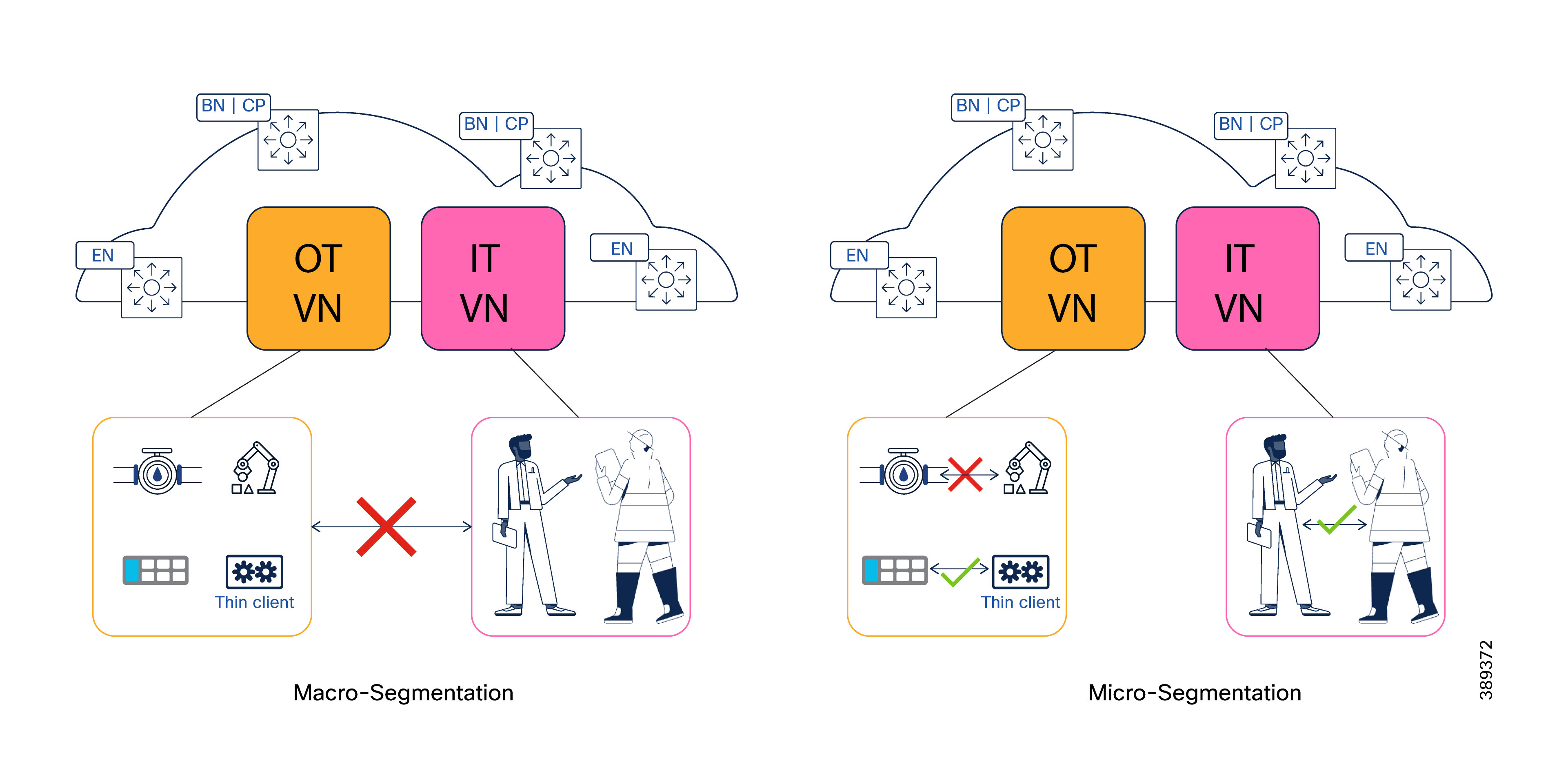
Cisco TrustSec provides scalable, policy-based micro-segmentation that is independent of IP addressing. In manufacturing networks, TrustSec must be applied using assumptions and priorities that differ from enterprise IT environments.
OT environments prioritize availability, predictable behavior, and controlled recovery over highly dynamic, identity-driven enforcement. As a result, TrustSec designs for manufacturing favor stable, zone-oriented segmentation models aligned with production areas, cells, or processes, rather than user-centric or rapidly changing policies.
In this CVD, TrustSec is used to enforce intra-domain policy within a Virtual Network, complementing VRF-based macro-segmentation. This layered approach establishes clear domain boundaries while enabling controlled communication within OT zones, consistent with industrial security best practices.
How OT Segmentation Differs from Campus Networks
Manufacturing environments differ from campus networks in several fundamental ways that directly influence TrustSec design:
● Zone-based segmentation is typically sufficient: segmentation commonly aligns with physical cells, areas, or process zones. Within a zone, continuity of operation is prioritized over fine-grained isolation between individual endpoints.
● Limited support for IEEE 802.1X: many OT endpoints do not support IEEE 802.1X. Where authentication is required, MAC Authentication Bypass (MAB) is commonly used, often with static or semi-static identity definitions.
● Process-centric access control models: access decisions are generally tied to production roles, system functions, or physical topology rather than user identity or endpoint type.
● Static addressing and VLAN dependency: OT devices frequently use static IP addressing and are not designed to move between VLANs or security zones dynamically.
● Variable TrustSec feature support at the access: Industrial switches deployed in cell and area zones may not support the full TrustSec feature set available on campus platforms, requiring careful selection of marking, propagation, and enforcement points.
These characteristics require a conservative and intentional TrustSec deployment model that minimizes operational risk while still enabling meaningful segmentation.In manufacturing environments, communication patterns are driven primarily by production processes rather than by device type. Controllers, field devices, HMIs, and auxiliary systems that participate in the same production process frequently require unrestricted lateral communication, while communication across processes must be tightly controlled.
For this reason, TrustSec segmentation in manufacturing networks should be anchored to process, line, or cell context, with device role treated as a secondary attribute.The following table illustrates an example process-oriented Scalable Group Tag (SGT) model aligned with common manufacturing layouts.
Table 10. Process-Oriented SGT Examples
| Process / Zone |
Example Assets |
Example SGT |
Scope |
| Body Shop – Line 1 |
PLCs, I/O, HMIs, cameras |
SGT_BODY_L1 |
Single production line |
| Body Shop – Line 2 |
PLCs, robots, safety |
SGT_BODY_L2 |
Single production line |
| Paint Shop – Line 1 |
PLCs, drives, vision |
SGT_PAINT_L1 |
Single production line |
| Assembly – Line A |
PLCs, HMIs, interlocks |
SGT_ASSEMBLY_A |
Single production line |
| Cross-Area Safety |
Safety PLCs, interlocks |
SGT_SAFETY_GLOBAL |
Multi-area |
| Engineering Access |
Engineering workstations |
SGT_ENG |
Plant-wide |
| Shared OT Services |
Historians, OPC UA |
SGT_OT_SERV |
Plant-wide |
| Vision Backend |
Vision servers, AI |
SGT_VISION_BACKEND |
Plant-wide |
| Shared Infrastructure |
AD, DNS, NTP |
SGT_INFRA |
Plant-wide |
TrustSec Segmentation Design Principles for OT Networks
This CVD adopts a pragmatic TrustSec usage model aligned with established Cisco industrial security guidance.
Detailed TrustSec design options, platform capabilities, and industrial deployment considerations are documented in the Cisco Industrial Security Design Guide. This CVD aligns with that guidance and does not attempt to redefine TrustSec behavior for OT environments.
The sections that follow describe how the solution applies TrustSec marking, propagation, and enforcement specifically within an SD-Access-based manufacturing architecture, taking into account OT operational constraints and SD-Access fabric behavior.
TrustSec Classification in OT Environments
In OT environments, SGTs can be assigned using different levels of granularity, depending on how segmentation is structured. In many manufacturing networks, segmentation is aligned with VLANs or subnets that represent production cells, areas, or processes. In these cases, SGT assignment is typically static, with a VLAN mapped to a single SGT. During the Anycast Gateway creation workflow in SD-Access, Catalyst Center enables VLAN-to-SGT mapping, providing a structured and scalable mechanism for tag assignment across the fabric.
However, some industrial devices within the same process may require differentiated access privileges. For example, an interlocking PLC or a supervisory controller may need a distinct security tag to support interlock or coordination functions that are not required by other devices in the same cell. In such scenarios, dynamic SGT assignment enables more granular classification by assigning tags based on device identity, profiling, or authentication context rather than VLAN membership.
In practice, OT environments rely on classification mechanisms that differ from traditional IT models. Most industrial endpoints do not support IEEE 802.1X; therefore, identity is commonly established using MAC Authentication Bypass (MAB), device profiling, or static endpoint definitions in Cisco ISE. In addition, most OT endpoints use static IP addressing; therefore, authorization policies should not result in VLAN changes, as this could disrupt control communication and device operation.
For OT access ports, this CVD recommends the use of open authentication. This approach allows limited communication prior to authentication, ensuring that industrial endpoints can successfully complete the authentication process without operational disruption, while still enabling SGT assignment through Cisco ISE policies.
Depending on the architecture, authentication may occur at the fabric edge, Extended Node (EN), Policy Extended Node (PEN), or on non-fabric nodes attached to the fabric. In SD-Access deployments, authentication and authorization policies and port configurations are automatically pushed by Catalyst Center to the fabric edge, EN, and PEN devices. When authentication is performed on non-fabric devices, configuration to support authentication should be deployed using configuration templates.
The implications of these marking and authentication models on TrustSec enforcement placement are discussed in the next sections.
TrustSec Propagation Across SD-Access and Non-Fabric Domains
Once assigned, Security Group Tags (SGTs) must be propagated to the enforcement point to enable policy-based segmentation. Within the SD-Access fabric, SGT propagation is primarily performed inline in the data plane. This is achieved through:
● VXLAN header tagging between fabric edges, border nodes, and intermediate fabric nodes
● Inline TrustSec tagging between fabric edges and Policy Extended Nodes (PENs)
These mechanisms are transparent to endpoints and require no manual configuration after fabric provisioning. As a result, SGT context is preserved end-to-end across the fabric as traffic flows between nodes. When non-fabric switches are connected below the fabric, SGT propagation depends on platform capabilities.
● If the switch supports TrustSec inline tagging, SGTs can continue to be propagated in the data plane through templates or local configuration.
● If inline tagging is not supported, SGT information must be distributed through the control plane from the authenticating device or via Cisco ISE using SXP (Security Group Tag eXchange Protocol).
SXP enables the exchange of SGT information between devices that do not natively support inline TrustSec tagging, ensuring that policy context can be extended beyond the fabric edge. Designers must ensure that SGT context reaches the enforcement point even when intermediate devices are not TrustSec-aware.
TrustSec Enforcement Models in OT Designs
TrustSec enforcement placement depends on how SGTs are assigned in the OT segmentation model. In manufacturing environments, enforcement models often reflect a combination of static VLAN-based SGT mapping and dynamic SGT assignment, rather than a single approach.
● Dynamic SGT assignment (identity-based classification). When VLANs are not mapped to SGTs and tags are assigned dynamically, enforcement should occur at the access port where the OT endpoint is connected. Depending on the architecture, this access port may reside on a fabric edge node, an Extended Node (EN), a Policy Extended Node (PEN), or a non-fabric switch that supports TrustSec enforcement. In this model, enforcement must be disabled on fabric edge interfaces facing PENs and on PEN uplinks, with enforcement remaining active only on PEN access ports. These exceptions are applied using Catalyst Center templates.
● Static SGT assignment (VLAN-to-SGT mapping). When VLAN-to-SGT mapping is used, enforcement occurs automatically at the fabric edge, which acts as the Layer 3 boundary. This model requires no additional configuration and aligns naturally with SD-Access policy enforcement.
● Mixed SGT assignment models (static + dynamic). Refers to mixed models that combine VLAN-to-SGT mapping and dynamic SGT assignment. This model requires careful design and validation and should be applied when operational requirements demand differentiated tagging within shared VLANs. This model is not covered in this guide.
Dynamic and Static models are illustrated below for reference. The diagrams compare SGT classification, propagation and enforcement on the different scenarios (Dynamic, Static SGTs and Mixed SGT assignement)
When using non-fabric switches for TrustSec, push required configurations via templates or local configuration. This includes:
● AAA policies
● Access port configurations
● Enforcement
● Propagation
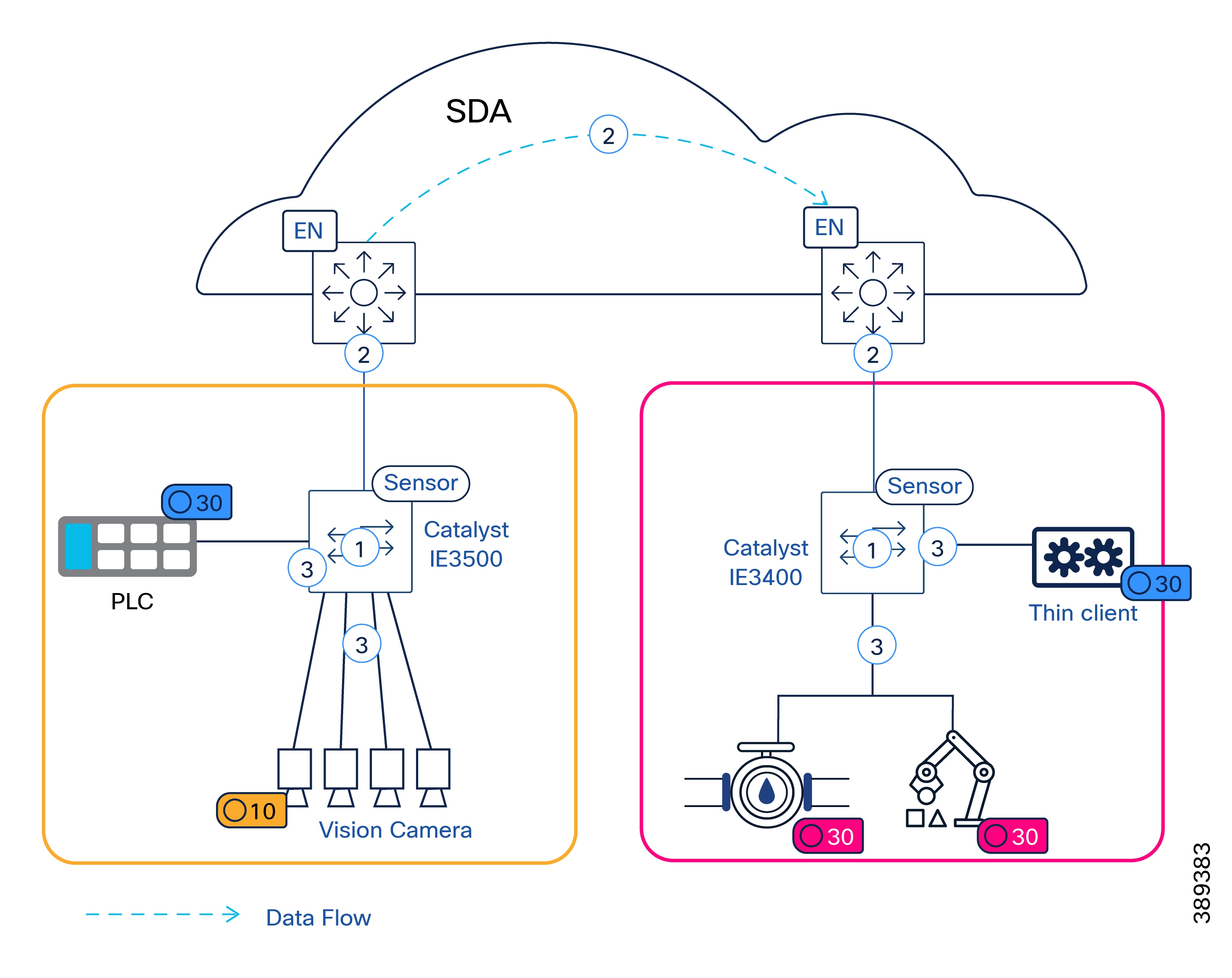
Table 11. Legend of Dyanamic SGT assignment Figure 16.
| Number |
Description |
| 1 |
Classification is dynamic. SGT assigned when endpoint authenticates in access port |
| 2 |
SGT is propagated on data plane between IE switches and fabric edges and inside the fabric (VXLAN) |
| 3 |
Policies are enforced on egress port at the access. |
Note: Enforcement between fabric edge and IE switch should be disabled to avoid incorrect enforcement
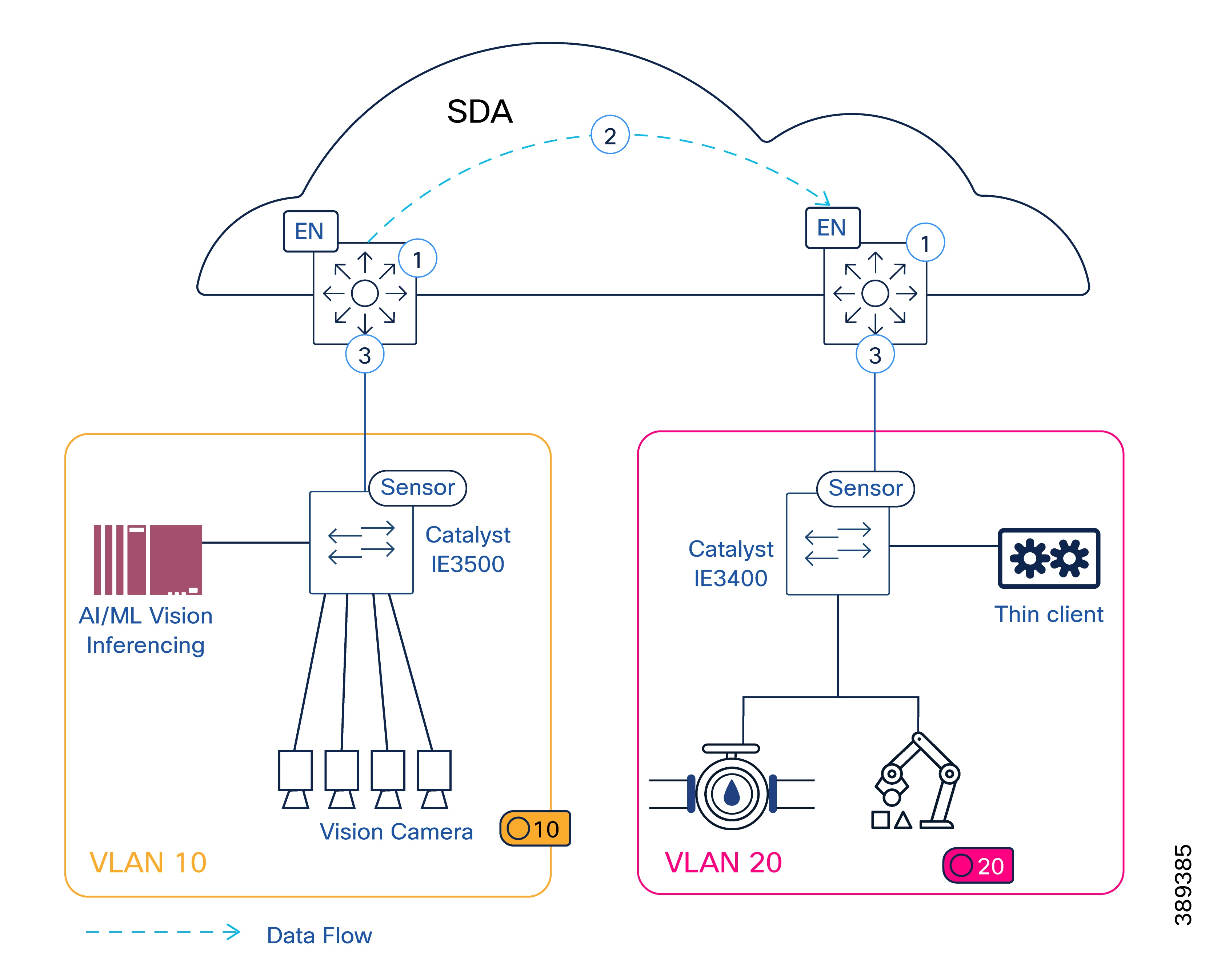
Table 12. Legend of static SGT assignment Figure 17.
| Number |
Description |
| 1 |
Classification is static, VLAN is mapped to SGT on Catalyst Center and configured on fabric edges (i.e. VLAN 10 > SGT 10) |
| 2 |
SGT is propagated on VXLAN header |
| 3 |
Policies are enforced on fabric edge downlinks |
Scale and Platform Considerations
TrustSec design must account for platform and scale limits across fabric edges, PENs, and Cisco ISE. Designers should reference the Cisco SD-Access Design Guide, the TrustSec Platform Capability Matrix, and the Cisco Industrial Security Design Guide when defining policy scope and enforcement placement.
Default-Deny Policy Considerations in SD-Access Based Manufacturing Networks
Default-deny segmentation is a common security objective in SD-Access designs; however, in manufacturing environments it must be applied deliberately to avoid unintended disruption to control, safety, and commissioning workflows.
In OT networks, many endpoints exhibit asymmetric or non-deterministic communication patterns, rely on broadcast or discovery mechanisms, or remain silent until contacted. Applying default-deny without careful staging can therefore block legitimate industrial traffic.
In this CVD, default-deny is supported with the following manufacturing-specific considerations:
● Default-deny policies should align with zone-based segmentation, rather than per-endpoint isolation.
● Policies must explicitly permit:
◦ Industrial discovery and commissioning traffic
◦ Required control, supervisory, and recovery communication paths.
◦ Network Management and control traffic
● Enforcement placement must avoid duplicate or conflicting policy application, particularly in designs that include Policy Extended Nodes (PENs) or non-fabric switches below the fabric edge.
● Default-deny should be introduced incrementally and validated during commissioning and after topology or application changes.
When implementing a default-deny (whitelist) model in SD-Access, organizations must ensure that fabric infrastructure and management traffic remain uninterrupted. The OT-specific guidance in this CVD complements standard SD-Access best practices for policy staging and enforcement.
The following adjustments are required to maintain fabric stability while enforcing a Zero Trust posture:
● Underlay & LAN Automation: Disable CTS role-based enforcement on all Layer 3 uplinks used for the fabric underlay. For new LAN Automation sessions, this is handled automatically starting with Cisco Catalyst Center release 2.3.7.4.
● Access Points and Extended Nodes: Use the Template Editor to disable CTS role-based enforcement on VLANs dedicated to Access Points and Extended Nodes. This ensures that infrastructure management traffic is not dropped by the default-deny policy. This process is automated starting with Cisco Catalyst Center release 2.3.7.6.
● Policy Extended Nodes (PEN):
◦ Disable CTS role-based enforcement on fabric edge downlinks facing a PEN.
◦ Disable CTS role-based enforcement on PEN uplinks and downlinks connecting to fabric edge nodes or other PENs. This ensures that SGT tags are propagated but not enforced on the transit links between the PEN and the fabric edge.
● Policy Staging: Before moving to a global default-deny state, utilize "Monitor Mode" and "Policy Analytics" within Cisco Catalyst Center to identify and permit all required industrial protocols and infrastructure flows.
● Reference Documentation: For detailed configuration steps on the whitelist model, refer to the Cisco TrustSec Whitelist Model with SD-Access Guide.
Cyber Vision for OT Visibility in SD-Access Based Manufacturing Networks
In this CVD, Cisco Cyber Vision is used as the OT visibility platform. Its role is to provide:
● Visibility into industrial assets connected to the network
● Insight into industrial communication patterns
● Context to support risk assessment and informed segmentation decisions
Cisco Industrial Security Design Guide provides comprehensive guidance on OT security architecture, Cyber Vision capabilities, and security workflows. This document focuses only on the SD-Access specific considerations relevant to integrating Cyber Vision into a dual-fabric manufacturing network.
Cyber Vision Deployment in SD-Access Architecture
The figure below illustrates the placement of Cisco Cyber Vision Center and sensors in an SD-Access-based manufacturing network. Sensors observe OT traffic on access-facing interfaces and forward metadata to the Cyber Vision Center using a dedicated collection VLAN carried over the SD-Access fabric.
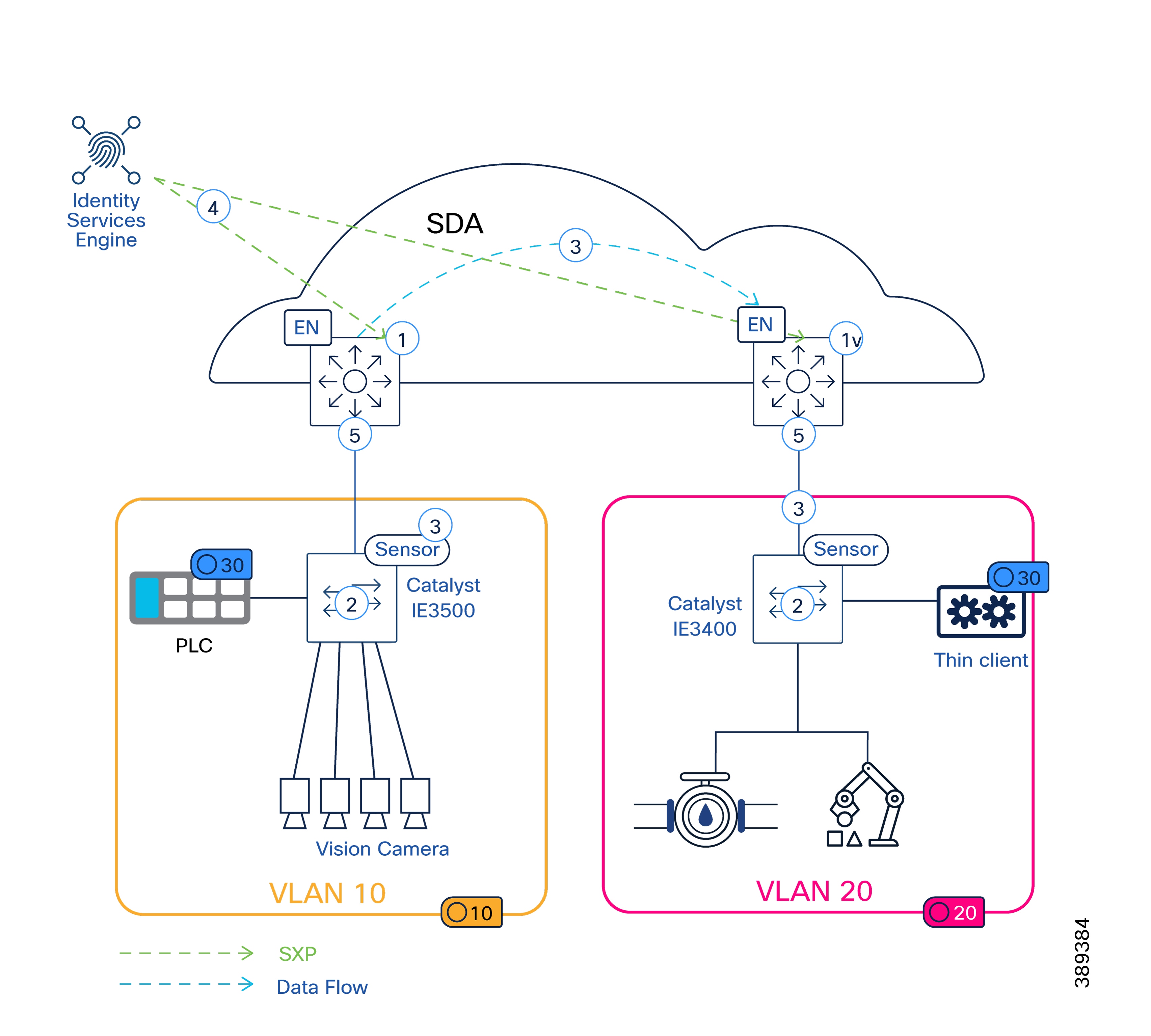
In this architecture, Cisco Cyber Vision components are deployed as follows:
● Cyber Vision Center is deployed outside the SD-Access fabric with Cisco plantwide applications.
● Cyber Vision sensors may be enabled on:
◦ SD-Access fabric edge nodes (for example, Catalyst 9300, IE9300)
◦ Industrial Ethernet switches connected to the fabric (for example, IE9300, IE3500, IE3400, IE-3300-8T2S)
SD-Access Specific Considerations for Cyber Vision Integration
When integrating Cisco Cyber Vision with an SD-Access based manufacturing network, the following considerations apply:
● Sensor enablement and traffic capture:
◦ Cyber Vision sensor enablement relies on Catalyst Center templates to configure capture VLANs and monitoring sessions (ERSPAN).
◦ The capture VLAN used for ERSPAN is local to each switch. IP addressing on this VLAN is locally significant and may be reused across devices, as it is not routed through the fabric.
● Fabric connectivity for sensor-to-center communication
◦ A Layer 3 VNI in Fabric A must be created for the Cyber Vision collection VLAN to allow sensors to communicate with the Cyber Vision Center.
◦ End-to-end MTU consistency is required across the SD-Access fabric and the entire sensor-to-center path. Inconsistent jumbo-frame configuration may prevent sensors from establishing or maintaining connectivity with the Cyber Vision Center.
● Platform-specific considerations
◦ On Catalyst IE3400 and IE3300 platforms, the ERSPAN capture VLAN must be removed from all switch ports to avoid unintended forwarding behavior.
● Traffic visibility scope
◦ Although Cyber Vision sensors can dissect VXLAN-encapsulated traffic, the recommended approach in manufacturing environments is to monitor access-facing downlinks only, rather than traffic within the fabric overlay.
◦ Sensors may use overlay VLAN interfaces to perform active endpoint discovery, while continuing to observe OT traffic on access VLANs.
● Sensor deployment
◦ Sensors are deployed and managed using the Cyber Vision Management Extension (at the time this CVD was written).
● Capture VLAN containment
◦ Catalyst Center provides the ability to control VLAN trunking on devices with SD-Access roles. This capability should be used to ensure that the Cyber Vision capture VLAN is not propagated beyond the local switch.
◦ For non-fabric switches, VLAN containment must be enforced explicitly using Catalyst Center templates or local switch configuration to prevent the capture VLAN from being extended unintentionally.
Detailed configuration example is documented in Appendix – CV deployment.
Secure Equipment Access (SEA) in SD-Access Based Manufacturing Networks
In manufacturing environments, a common requirement is to allow authorized personnel to remotely troubleshoot or maintain industrial assets without weakening network security or disrupting SD-Access segmentation. For example, a field technician may need to access a PLC on the plant floor, without requiring IT to open inbound firewall ports or expose the OT network to external connections.
Cisco SEA addresses this requirement by providing secure, Zero Trust–based remote connectivity to OT assets. SEA enables operations, maintenance, and support teams to access industrial devices remotely while preserving SD-Access segmentation and without introducing unsolicited inbound connections into the OT network. This approach reduces the need for on-site service interventions while maintaining strong security controls and operational integrity.
In this CVD, SEA is used to:
● Enable secure remote access to industrial assets for troubleshooting and operational lifecycle management.
● Reduce on-site intervention, increasing operational efficiency, minimizing downtime, and optimizing resource allocation.
● Enforce Zero Trust Network Access (ZTNA) principles for OT environments, ensuring that every session is authenticated and authorized.
● Integrate with Cisco IoT Operations Dashboard for centralized policy, visibility, and access management.
Integration of SEA with Cisco Cyber Vision
Secure Equipment Access (SEA) is integrated with Cisco Cyber Vision through a shared IOx application model, enabling a unified and streamlined operational workflow. The SEA agent and the Cyber Vision sensor are packaged and deployed together as a single IOx application on the same industrial platform, simplifying installation and reducing operational overhead.
All deployment, management, and lifecycle operations are performed through Cisco Cyber Vision Center. SEA agents can also use Cyber Vision as a proxy to reach out the the Internet.
This integrated approach enables operators to combine OT visibility and secure remote access on the same infrastructure, using a consistent workflow and toolset.
For design guidance on SEA refer to Cisco Industrial Security Design Guide. This document only highlights key considerations for SEA deployment on SD-Access architecture.
SEA Deployment in SD-Access Architecture
In this CVD, SEA deployment aligns with Cyber Vision’s architectural and deployment principles within Software-Defined Access (SD-Access) manufacturing networks explained earlier.
● Deployment:
◦ Cyber Vision Center is deployed outside the SD-Access fabric.
◦ The combined Cyber Vision + SEA IOx application is deployed on:
- SD-Access fabric edge Nodes (e.g., Catalyst 9300, IE9300 series)
- Industrial Ethernet switches connected to the fabric (e.g. IE3400, IE3300, IE3500, IE9300)
◦ SEA is deployed via the Cyber Vision sensor management extension, allowing centralized orchestration.
● Connectivity to Secure Equipment Access Cloud
◦ Cyber Vision Center acts as proxy for SEA outbound connections.
◦ SEA connectivity is always initiated outbound by the agent, ensuring SD-Access segmentation is preserved and eliminating the need for inbound connections into the OT network. This is consistent with Zero Trust principles and minimizes attack surface.
● Centralized lifecycle management:
◦ Deployment, upgrades, and ongoing operations are managed from Cyber Vision Center.
● Segmentation and VRF alignment:
◦ SEA traffic adheres to SD-Access segmentation and VRF boundaries.
◦ Required routing is confined within the management VRF (e.g., “Fabric A”), consistent with other operational services.
● Multi-overlay reachability:
◦ SEA supports configuration of multiple IP addresses, enabling access to endpoints across different SD-Access overlays or virtual networks.
● Operational Isolation:
◦ Loss of Cyber Vision Center or SEA cloud connectivity does not affect real-time industrial traffic or control operations.
◦ SEA serves strictly as an operational access service—it is not a forwarding or control-plane dependency and does not introduce risk to production traffic.
Note: While the system supports SEA deployment using Catalyst Center Application Hosting as an alternative, this CVD does not validate or cover it.
When designing an SD-Access fabric for manufacturing, evaluate scale across fabric control-plane limits, policy capacity, traffic replication requirements, and management-plane sizing. Scale planning should reflect both day-1 deployment and day-2 growth (additional cells, VLANs, endpoints, sensors, and visibility/security services).
Fabric scale is primarily driven by endpoint density and the number of segmentation constructs required for the plant. These characteristics should be considered during planning and sizing to ensure the fabric is designed to meet operational and scalability requirements. Network devices: number of fabric edge, border, control plane nodes, plus any policy extended nodes and other Catalyst Center–managed devices.
● Virtual Networks (VNs) and IP pools/subnets required per manufacturing zone/cell.
● L2 and L3 services: number of L2VNIs (VLAN-backed) and L3VNIs (Anycast Gateway-backed) required for operations.
● Endpoint scale: wired and wireless OT/IT endpoints, including growth for sensors/cameras and temporary commissioning devices.
TrustSec scale is an important consideration in OT environments, as segmentation frequently spans multiple device classes and operational zones. These characteristics should be considered during planning and sizing.
● SGT and SGACL capacity on intended enforcement platforms (varies significantly by platform/software)
● Number of enforcement points (fabric edge vs PEN vs non-fabric enforcement)
● ISE scale model alignment (session count, profiling load, policy services, pxGrid integrations)
Reference: TrustSec Platform Capability Matrix and Cisco Industrial Security Design Guide
Bandwidth, Replication, and Platform Sizing
Platform sizing in SD-Access must be based on worst-case traffic conditions, replication behavior, and control-plane overhead, not average utilization. This applies to all SD-Access deployments. Cisco SD-Access sizing guidance recommends evaluating platforms when mapping workloads to fabric roles.
Industrial switches, fabric edge, border nodes and intermediate nodes must be sized to handle:
● Aggregate access bandwidth per cell or area, including expected oversubscription ratios
● Peak traffic conditions, not steady-state averages
● Concurrent traffic classes (control, supervisory, video, management, telemetry)
In manufacturing environments, this includes—but is not limited to—industrial imaging, historian uploads, engineering access, visibility tooling, and recovery traffic after link or node failures.
Failure and Recovery Scenarios
Sizing must explicitly account for failure conditions, including:
● Link or node failures causing traffic re-convergence.
● Temporary traffic amplification during endpoint re-learning.
● Control-plane updates.
Cisco guidance emphasizes that failure scenarios, not steady-state operation, drive sizing in SD-Access fabrics.
Cisco recommends provisioning sufficient headroom to support:
● Incremental addition of cells, VLANs, and endpoints
● Introduction of new workloads (for example higher-resolution vision, additional sensors, or security services)
● Software feature evolution that increases control-plane or telemetry load
This avoids premature hardware refresh and ensures fabric stability as the deployment evolves.
PRP scale is commonly constrained by node-table size, VLAN scoping, and MAC growth. The PRP node-table scale in Catalyst IE3400 is 1000 entries (starting at IOS-XE 17.16)
It is recommended to use PRP Supervision VLAN Aware mode operation to support scale by limiting the number of nodes learned on PRP node table.
It is recommended to include growth margin for commissioning devices and temporary endpoints.
Management Plane Sizing, Latency, and Operational Scale
Management components must be sized for both inventory scale and operational workload:
● Catalyst Center: number of devices, assurance/telemetry volume, backups, and job concurrency
● ISE: authenticated sessions, profiling load, policy evaluation rate, integrations
The round-trip time (RTT) between Catalyst Center and managed devices should be less than 100ms for optimal performance; the maximum supported latency is 200ms RTT. Latency between 100–200ms is supported but may increase execution time for functions such as inventory collection and fabric provisioning.
Layer 2 Flooding and Underlay Multicast Scale
If you enable overlay flooding for industrial discovery/commissioning use cases, account for the additional replication state and behavior.
● When multicast-based replication is used in the underlay for BUM/flooding behaviors, underlay multicast routing must be in place to support that transport behavior.
● Validate IGMP/PIM and multicast state scaling if protocols/workloads rely on it now or may be introduced later (for example EtherNet/IP multicast-based patterns).
Reference: Cisco Industrial Security Design Guide
vPLC and Data Center / Virtualization Integration
For vPLC or real-time workloads hosted in a data center or edge cluster:
● Validate vendor workload limits (vPLC density per host/cluster, vNIC requirements, real-time interfaces)
● Validate throughput and jitter on “real-time” interfaces based on the virtualization provider guidance.
Control Plane and Border Node Scale
Validate SD-Access control-plane and border scale based on:
● Total number of endpoints (EIDs) expected
● Number of VNs and routing adjacencies at the border
● External route table scale and redistribution design (if applicable)
Reference: Cisco Industrial Security Design Guide
Latency and Jitter Expectations for OT Workloads
In manufacturing networks, performance must be evaluated beyond average latency values. Consistency of delivery is often more critical than absolute delay, particularly for cyclic control, supervision, and recovery-related traffic.
Key considerations include:
● Steady-state behavior and recovery: evaluate latency and delay variation both during normal operation and during transient events such as endpoint relearning, topology changes, or link/node recovery. These events are often the primary contributors to jitter.
● Jitter as the dominant risk factor: in OT environments, jitter is typically more disruptive than fixed latency. Control applications can usually tolerate a slightly higher but consistent delay; however, variation in delay can result in missed cycles, timeouts, or unstable application behavior.
● Relative jitter guidance: rather than defining absolute thresholds, jitter should be evaluated relative to the application cycle time. As a commonly accepted engineering guideline:
◦ Acceptable jitter is often kept below 10–20% of the application cycle time
◦ For more sensitive supervisory or time-critical control traffic, designs commonly target <5–10% of the cycle time
◦ These values are illustrative and must be validated against vendor specifications and application requirements.
● Impact of scale-related features: features such as telemetry, flooding, traffic replication, and visibility services increase control-plane and data-plane load. Platform sizing and feature placement must ensure that these functions do not introduce unbounded jitter under peak or failure conditions.
This CVD does not define universal latency or jitter thresholds. Acceptance criteria must be validated against:
● Automation vendor requirements
● Application cycle times
● Plant recovery and availability objectives
Design Recommendations Summary
The following table consolidates the key architectural, operational, and scaling recommendations described throughout this CVD. The recommendations are organized by design domain to support planning, validation, and deployment reviews. They derive from the architecture description, configuration guidance, operational constraints, and referenced figures across the document.
Table 13. Design Recommendations Summary
| Design Domain |
Validation Item |
Rationale / Design Intent |
✔ / ✖ / N/A |
| Overall Architecture |
Two fully independent SD-Access fabrics (LAN A, LAN B) are deployed |
Prevents shared convergence domains and cascading failures |
|
| Each fabric has dedicated edge, control plane, and border nodes |
Ensures full fault isolation per fabric |
||
| No forwarding or control-plane dependencies exist between fabrics |
Maintains deterministic failure behavior |
||
| Traffic Placement Strategy |
Application traffic placement is driven by tolerance to loss/interruption |
Avoids overuse of redundancy and unnecessary complexity |
|
| Time-critical control traffic is explicitly identified |
Enables selective PRP protection |
||
| Non-critical, IT, and management traffic is confined to LAN A |
Reduces operational and validation scope |
||
| PRP Usage |
PRP is enabled only for zero-interruption applications |
Limits bandwidth duplication and PRP scale impact |
|
| PRP VLAN Design |
PRP VLANs exist as identical L2VNIs in LAN A and LAN B |
Required for correct PRP frame delivery |
|
| VLAN IDs and VNIs are consistent across fabrics |
Ensures deterministic duplication behavior |
||
| Layer-2 flooding is enabled where required (e.g., PROFINET DCP) |
Supports discovery and commissioning workflows |
||
| Layer 3 Boundaries |
Default gateways for PRP VLANS |
Prevents PRP-incompatible multi-attached gateways |
|
| No L3VNIs or Anycast gateways exist for PRP VLANs in LAN B |
Preserves correct PRP operation |
||
| Non-PRP VLANs are routed only in LAN A |
Simplifies routing and fault domains |
||
| PRP RedBox Placement |
PRP RedBoxes are deployed only below a fabric edge |
Keeps PRP transparent to the SD-Access fabric |
|
| SD-Access fabric nodes do not perform PRP functions |
Avoids coupling PRP behavior to fabric convergence |
||
| Virtualization layer has a virtual switch with PRP support |
Enables PRP protection for virtual workloads |
||
| PRP Scale |
PRP supervision VLAN-aware mode is enabled |
Controls PRP node-table growth |
|
| PRP supervisory frames are VLAN-tagged and scoped |
Prevents cross-cell PRP learning |
||
| RedBox node-table capacity has growth margin |
Supports commissioning and expansion |
||
| Industrial Access & PENs |
PRP-capable industrial switches operate as PENs only |
Preserves OT operational independence |
|
| Industrial switches not supporting PRP don't assume fabric roles |
Avoids SD-Access lifecycle constraints in OT |
||
| PEN management connectivity is provided via LAN A only |
Simplifies operations and recovery |
||
| PRP Commissioning & Operations |
RedBoxes are onboarded using controlled workflows |
Prevents transient Layer-2 loops |
|
| LAN B links are connected only after PRP is fully configured |
Avoids unintended traffic duplication |
||
| Replacement procedures rely on Catalyst Center |
Ensures configuration consistency |
||
| Quality of Service (QoS) |
QoS is configured end to end to prioritize critical traffic |
Ensures low latency, low jitter, and lossless behavior for critical traffic, even under congestion. |
Validation Summary and Results
This section summarizes the validation results for the SD-Access-based dual-fabric manufacturing architecture. It documents observed behavior under scale, congestion, failure, and impairment conditions. The validation verified that the proposed design maintains predictable and uninterrupted operation of time-critical industrial applications while preserving fault isolation and graceful degradation for non-critical traffic.
Validation Scope and Objectives
The validation process confirmed the following design objectives:
● Loss-free delivery of prioritized industrial traffic under congestion
● Bounded latency and low jitter behavior for time-critical applications
● Fault isolation between dual fabrics during link, node, and control-plane failures
● Correct operation of PRP-protected applications independent of fabric convergence
● Controlled degradation of non-critical and best-effort traffic during stress conditions
The validation environment simulated a scaled manufacturing deployment with multiple time-critical workloads and realistic endpoint density.
Table 14. Application Validated Scale
| Parameter |
Validated Scale |
| Time-critical applications in a single host |
12 |
| Virtual PLC instances in a single host |
11 |
| Time distribution application |
1 |
| PROFINET endpoints |
1200 |
Each vPLC operated in its own VLAN to reflect typical industrial segmentation and commissioning practices.
Traffic and Congestion Validation
To validate QoS behavior under stress, the test injected synthetic traffic with multiple profiles alongside production-like industrial workloads.
The tests included:
· Sustained operation at approximately 40% overall utilization.
· Short-duration congestion scenarios exceeding 100% utilization to force queue contention and packet drops.
During congestion:
· Priority traffic representing PROFINET-like treatment experienced zero packet loss.
· Best-effort and lower-priority traffic experienced packet loss by design.
These results confirm that QoS policies effectively protect time-critical industrial traffic while allowing non-critical traffic to degrade gracefully under congestion.
Failure and Recovery Validation
The validation process executed failure scenarios across both fabrics to verify fault isolation, convergence behavior, and PRP redundancy. Tests included link, node, and control-plane failures across access, distribution, and data center paths.
Table 15. Failure Scenarios
| Failure Scenario |
Observed Impact |
| Fabric border node failure |
No impact to time-critical applications |
| Fabric control plane node failure |
No impact to time-critical applications |
| Fabric edge power removal |
No impact to time-critical applications |
| PEN–Fabric Edge link failure |
No impact to time-critical applications |
| Fabric Edge–Data Center fabric edge link failure |
No impact to time-critical applications |
| Data Center to LAN A |
No impact to time-critical applications; loss of management traffic to Data Center |
In all scenarios, PRP-protected applications remained operational, and the system observed no time-critical application failures.
The tests introduced network impairments to simulate degraded transport conditions, including:
· Increased latency on one fabric relative to the other.
· Packet loss injected on a single LAN.
Despite these impairments:
· PRP-protected applications continued operating without interruption.
· Time-critical applications experienced no failures.
· The system isolated degradation to the impaired fabric, with no cross-fabric impact.
This behavior confirms the correct redundancy and fault isolation characteristics of the dual-fabric design.
Latency and Jitter Measurements
We measured latency, jitter, and packet loss using Provider Connectivity Assurance.
Key observations include:
· Priority traffic maintained bounded latency and low jitter, even during full congestion.
· Best-effort traffic experienced significant packet loss and higher jitter under stress.
Representative measurements appear below:
Table 16. Observed Latency, Jitter, and Packet Loss
| Metric |
Priority Traffic |
Best-Effort Traffic |
| Packet loss (congestion) |
0% |
Up to 82% |
| Maximum jitter (worst case) |
< 32 µs |
Up to 406 µs |
| Maximum end-to-end latency |
~50 µs |
Not bounded |
| Behavior during failures |
No interruption |
Temporary degradation |
These results demonstrate that Jitter, rather than absolute latency, represents the dominant risk factor for time-critical industrial traffic. Even when latency remains within acceptable bounds, excessive jitter can disrupt cyclic communication. In this validation, jitter for prioritized traffic remained tightly controlled while non-critical traffic absorbed the impact of congestion.
As a general engineering guideline, jitter variation should remain within approximately 10–20% of the nominal application cycle time, recognizing that exact thresholds depend on the application and require validation against automation vendor requirements.
Across all validation scenarios:
● No time-critical application failures were observed
● PRP redundancy ensured uninterrupted operation of critical applications
● During failures on LAN A, interruptions were observed only for non-critical traffic, including management and best-effort flows
● Fabric isolation behaved as designed, preventing congestion or failures in one fabric from impacting the other
QoS policies are provided as an example on how to prioritize PROFINET RT traffic. More traffic classes can be added to policies after evaluating other applications in the deployment.
mac access-list extended match_profinet
permit any any 0x8892 0x0
class-map match-any match_dscp_50
match dscp 50
class-map match-any cm_match_cos6
match cos 6
class-map match-any cm_match_profinet
match access-group name match_profinet
class-map match-all DSCP_50_Group
match qos-group 1
## Ingress Policy to be applied to ports facing border and intermediate Nodes
policy-map DSCP_50_in
class match_dscp_50
Set qos-group 1
## Egress Policy for links facing border and intermediate nodes.
policy-map pm_switch_to_switch_out
class match_dscp_50
priority level 1 percent 50
## Ingress policy for ports facing PEN
policy-map pm_1G_in
class cm_match_profinet
set dscp 50
class match_dscp_50
set dscp af13
## Ingress policy for ports facing DC
policy-map pm_25G_edgecloud_in
class cm_match_profinet
set dscp 50
class match_dscp_50
set dscp af13
## Egress policy for ports facing DC
policy-map pm_25G_edgecloud_out
class DSCP_50_Group
priority level 1 percent 50
## Ingress policy for ports facing PEN
policy-map pm_1G_out
class DSCP_50_Group
priority level 1
set cos 6
class class-default
bandwidth remaining percent 100
police rate percent 50 conform-action transmit exceed-action drop
class-map match-any match_dscp_50
match dscp 50
#### Egress Policy for links facing border and intermediate nodes.
policy-map pm_switch_to_switch_out
class match_dscp_50
priority level 1 percent 50
mac access-list extended Profinet_macacl
permit any any 0x8892 0x0
class-map match-any class_match_profinet_in
match access-group name Profinet_macacl
class-map match-any COS_6_Class
match cos 6
policy-map Profinet_in_policy
class class_match_profinet_in
set cos 6
class class-default
set cos 0
policy-map Profinet_out_policy
class COS_6_Class
priority
Enable iox
C9300#format usbflash1: ext4
C9300#config t
C9300(config)#iox
Configure capture interface VLAN: this IP is local to the switch and not routed, used for ERSPAN only
C9300(config)#vlan 2
C9300(config-vlan)#int vlan 2
C9300(config-if)# ip address 169.254.1.1 255.255.255.252
C9300(config-if)#no sh
Configure AppGigabitEthernet interface as trunk
C9300(config-if)#interface AppGigabitEthernet1/0/1
C9300(config-if)#sw mode trunk
Configure Monitor Session: define which traffic is sent to the sensor, use VLANs or interfaces
C9300(config-if)#monitor session 1 type erspan-source
C9300(config-mon-erspan-src)#source interface Gi1/0/1 - 2 both
C9300(config-mon-erspan-src)#no shutdown
C9300(config-mon-erspan-src)#destination
C9300(config-mon-erspan-src-dst)#erspan-id 2
C9300(config-mon-erspan-src-dst)#mtu 9000
C9300(config-mon-erspan-src-dst)#ip address 169.254.1.2
C9300(config-mon-erspan-src-dst)#origin ip address 169.254.1.1
C9300(config-mon-erspan-src-dst)#end
The following figure shows how to configure IP addresses and VLANs on Cyber Vision management extension wizard