CPwE CIP Security Design Considerations
This chapter describes basic design considerations when implementing CIP Security in an IACS architecture. This CRD offers basic guidance for CIP Security, including security policy considerations incorporating a threat model overview, alignment with ISA/IEC 62443, technology considerations with TLS/DTLS protocols, and architectural considerations with network segmentation, which IACS networking personnel could use to design and deploy their architecture. This also includes the CPwE CIP Security Solution use cases and their various components and their relation to each other.

Note![]() The client/server terminology is commonly used with TCP and TLS/DTLS connections and originator/target for CIP connection. However, for simplicity of this document, the terms client/server will be generalized and used throughout this document when discussing the behavior associated with a connection of an IACS device. The client initiates a connection and the server listens for and accepts a connection.
The client/server terminology is commonly used with TCP and TLS/DTLS connections and originator/target for CIP connection. However, for simplicity of this document, the terms client/server will be generalized and used throughout this document when discussing the behavior associated with a connection of an IACS device. The client initiates a connection and the server listens for and accepts a connection.
System Components
The following tables and section list the Rockwell Automation and Cisco components that are involved in this reference design:
- Table 2-1 lists the Rockwell Automation and Cisco network components.
- Table 2-2 lists the Rockwell Automation IACS hardware components.
- Table 2-3 lists the Rockwell Automation software components.
- Additional Resources lists additional resources related to Rockwell Automation products.
ControlLogix 55801 controller |
|||
|
1.The following note lists the catalog numbers with the associated firmware versions that currently support CIP Security. |
Note At the time of this publication, Rockwell Automation products supporting CIP Security include the following:
- ControlLogix 5580 controllers starting with version 32 or higher (GuardLogix controllers do not support CIP Security)
(In ControlLogix/GuardLogix 5570-based systems, retrofit the latest CIP Security enabled 1756-EN4TR communication module to secure EtherNet/IP communications.)
- 1756-EN4TR communication module
- Kinetix 5700 servo drives starting with firmware version 11.xx or higher
- FactoryTalk Linx starting with version 6.11 or higher
To see if an IACS device supports CIP Security, refer to the specific vendor IACS device user manual, technical specification, or release notes publications.
FactoryTalk Services Platform2 |
|||
|
2.The following note lists the catalog numbers with the associated firmware versions that currently support CIP Security. |
Note In the initial release of CIP Security, it is required to install FactoryTalk System Services and FactoryTalk Policy Manager software on the computer that hosts the FactoryTalk Network Directory.
- FactoryTalk System Services is the Certificate Authority (CA), which is the service that signs and issues client certificates to give assurance for the authenticity of a a communicating party. It runs as a service in the background to help enable the deployment of CIP Security policies configured in the FactoryTalk Policy Manager commissioning tool.
- FactoryTalk Policy Manager is the commissioning tool graphical user-interface (GUI) used to configure, deploy, and view the system communication security policies.
Additional Resources
For more information and a list of Rockwell Automation products supporting CIP Security including software and hardware, see:
- FactoryTalk Policy Manager Getting Results Guide, publication FTALK-GR001—Describes how to install and use FactoryTalk System Services and FactoryTalk Policy Manager.
https://literature.rockwellautomation.com/idc/groups/literature/documents/gr/ftalk-gr001_-en-e.pdf - FactoryTalk Security System Configuration Guide Quick Start, publication FTSEC-QS001—Describes how to use FactoryTalk Services Platform with FactoryTalk Security.
https://literature.rockwellautomation.com/idc/groups/literature/documents/qs/ftsec-qs001_-en-e.pdf - FactoryTalk Linx Getting Results Guide LNXENT-GR001—Describes information on installing, navigating, and using FactoryTalk Linx.
https://literature.rockwellautomation.com/idc/groups/literature/documents/gr/lnxent-gr001_-en-e.pdf - CIP Security with Rockwell Automation Products Application Technique SECURE-AT001—Describes components and concepts that are part of the Rockwell Automation method of implementing CIP Security in an IACS.
https://literature.rockwellautomation.com/idc/groups/literature/documents/at/secure-at001_-en-p.pdf - ControlLogix 5580 and GuardLogix 5580 Controllers User Manual, publication 1756-UM543—Describes how to design, implement, and maintain an industrial control system that uses ControlLogix or GuardLogix based controllers.
https://literature.rockwellautomation.com/idc/groups/literature/documents/um/1756-um543_-en-p.pdf - ControlLogix EtherNet/IP Network Devices User Manual, publication 1756-UM004—Describes how to use ControlLogix EtherNet/IP communication modules with a Logix 5000™ controller and communicate with devices on the EtherNet/IP network.
https://literature.rockwellautomation.com/idc/groups/literature/documents/um/1756-um004_-en-p.pdf - Kinetix 5700 Servo Drives User Manual, publication 2198-UM002—Describes how to use Kinetix 5700 drive system with associated power supplies, single-axis inverters, dual-axis inverters, and accessory modules in a Logix 5000 control system.
https://literature.rockwellautomation.com/idc/groups/literature/documents/um/2198-um002_-en-p.pdf
IACS Security Policy Considerations
In traditional IACS applications, much of the data remained in isolated systems not connected to other networks, which made understanding the threat landscape for IACS networks straightforward as most threats were local. As a result, many IACS networks and assets were designed and built before any industrial security threats surfaced, therefore industrial communication protocols did not have any security mechanisms.
With technological advances in IIoT and increased accessibility through converged IACS network infrastructure, data that was once kept in isolation is now readily available to management to help determine inefficiencies and aid in decision-making. IIoT helps offer the promise of business benefits by using innovative technology such as mobility, collaboration, analytics, and cloud-based services. It represents a gateway to digital transformation that connects plant-level or site-level and enterprise networks and securely connects people, processes, and technologies by adding analytics capabilities to IACS assets on the plant floor. More connected operations can create more potential entrance points for industrial security threats. These threats can come in many forms—physical or digital, internal or external, malicious or unintentional.
The challenge for industrial operations is to develop a balanced security stance to take advantage of IIoT innovation while maintaining the integrity of industrial security best practices. A balanced security framework must address both technical (technology) and non-technical (policies and procedures) elements. The degree of hardening depends upon the required security stance. Business practices, corporate standards, security policies, application requirements, industry security standards, regulatory compliance, risk management policies, and overall tolerance to risk are key factors in determining the appropriate security stance.
Understanding the security threats, risks, and vulnerabilities of a system is the starting point for any security policy implementation. The following security terminology is used in this publication:
- Asset —What we are trying to help protect. It can include property, people, information, and data that has value to an organization.
- Threat —What we are trying to help protect our asset from. Threats are potential events where anything might exploit a vulnerability to breach security and therefore cause possible harm.
- Vulnerability —A weakness or gap in a device, software, or security program that can be exploited by threats to gain unauthorized access to an asset.
- Risk —Risks are the potential effects of events, which are caused by threats.
- Policies, procedures, and awareness —A plan of action around procedures and education to help protect company assets (risk management) and provide rules for controlling human interactions in IACS systems.
IACS Threat Model Overview
Threats are undesirable events where anything might exploit a vulnerability to cause negative impacts on the operation or availability of equipment. Understanding threats to the IACS helps identify the appropriate countermeasures to mitigate them.
To better understand IACS threats, employ threat modeling, which is a preliminary step in a risk assessment to determine what the threats might be. A threat model identifies objectives and vulnerabilities and then defines countermeasures to mitigate the effects of threats to the system. Some considerations of threat modeling include addressing the following questions:
- What critical assets are in the IACS environment?
- What is the potential impact if something were to happen to one of those assets?
- What is the possible threat?
- What is a current threat in your IACS environment?
–![]() How difficult would it be to exploit?
How difficult would it be to exploit?
–![]() Would it require a low level or high level of skill?
Would it require a low level or high level of skill?
The threats today present themselves in many forms:
- External —Hackers seeking political or financial gain. A manufacturer’s intellectual property can be a lucrative target for hackers. They might want to disrupt an industrial operation for financial, competitive, or political reasons. It is important to acknowledge even organizations not in the critical infrastructure sector or not targets of financial or political attacks can experience collateral damage from external threats. A well-known example is the NotPetya malware, a cyberattack masquerading as ransomware that affected thousands of computers worldwide in 2016 and 2017.
- Internal —Disgruntled employees. This category includes current and former employees, contractors, and third-party integrators. All these entities are familiar with a control system and industrial network of an organization and can present security and safety threats. In 2009, a contracted security guard managed to install malicious code in the HVAC control system causing damage to pharmaceutical storage at a medical facility.
- Human error or accidental —Employee errors. One of the most common security risks comes from innocent mistakes. This could include employees or contractors who unwittingly make a network misconnection, download the wrong program to a controller, or plug an infected device into the system. At a nuclear power plant, an engineer updated software on a computer and after the update the computer rebooted. The reboot also reset the data on the control system causing safety systems to interpret the data as a drop in coolant water reservoirs, initiating a plant shutdown.
At a minimum, the threat model approach should include the following information:
- Asset Management ( Table 2-4 )
–![]() Detailed inventory of existing devices and software, including firmware revisions
Detailed inventory of existing devices and software, including firmware revisions
- Data Flows ( Table 2-5 )
–![]() Detailed observation and documentation of intended system functions and operation
Detailed observation and documentation of intended system functions and operation
–![]() Detailed observation and documentation of required data flows between devices
Detailed observation and documentation of required data flows between devices
–![]() Detailed observation and documentation of required access to devices
Detailed observation and documentation of required access to devices
- Identified Threats and Countermeasures ( Table 2-6 )
–![]() Detailed observation and documentation of potential threats and countermeasures
Detailed observation and documentation of potential threats and countermeasures
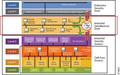
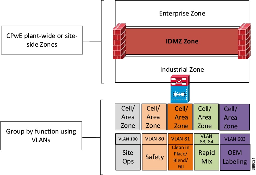
The CPwE logical model employs commonly used industry standards such as the Purdue Model and ISA95 to organize the functions within industrial operations into Levels, and then organizes the Levels into Security Zones based on ISA/IEC 62443, as shown in Figure 2-1.
Figure 2-1 CPwE Logical Zoning Based on Purdue Model and ISE/IEC 62443
IACS Asset Management
Identifying new IACS assets ( Table 2-4 ) that have been deployed or retired IACS assets that have been decommissioned provides the visibility needed to protect them and helps prioritize security efforts.
Once an IACS asset inventory has been procured, prioritize the assets:
–![]() How much revenue/profit does it generate?
How much revenue/profit does it generate?
–![]() What is the cost to replace it?
What is the cost to replace it?
FactoryTalk AssetCentre
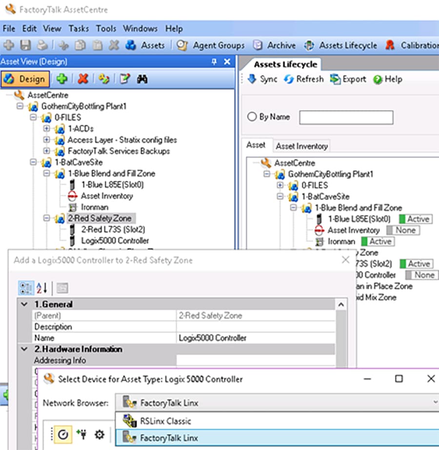
Secure, manage, version, track, and report IACS asset information for IACS with FactoryTalk AssetCentre software (Figure 2-2). The FactoryTalk AssetCentre server centrally tracks and manages configuration changes and restricts who can make changes. This server functionality assists with diagnostics and troubleshooting and reduces maintenance time for IACS assets. An accurate and current asset inventory documentation enables better ongoing management of IACS devices. It can also support backup and recovery in case there is a need to restore IACS devices.
Figure 2-2 FactoryTalk AssetCentre
FactoryTalk Network Manager
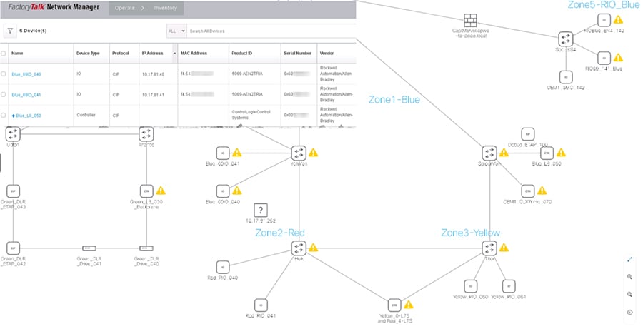
FactoryTalk Network Manager (FTNM) software is a network management tool (Figure 2-3). It is designed to help operation teams gain full visibility of network devices and IACS assets in the context of industrial operations and provides improved architecture availability and performance, leading to increased overall equipment effectiveness (OEE). It provides the capabilities to view the network topology and manage switch-level alarms as they happen for more improved decision-making.
Figure 2-3 FactoryTalk Network Manager
FactoryTalk Linx Browser
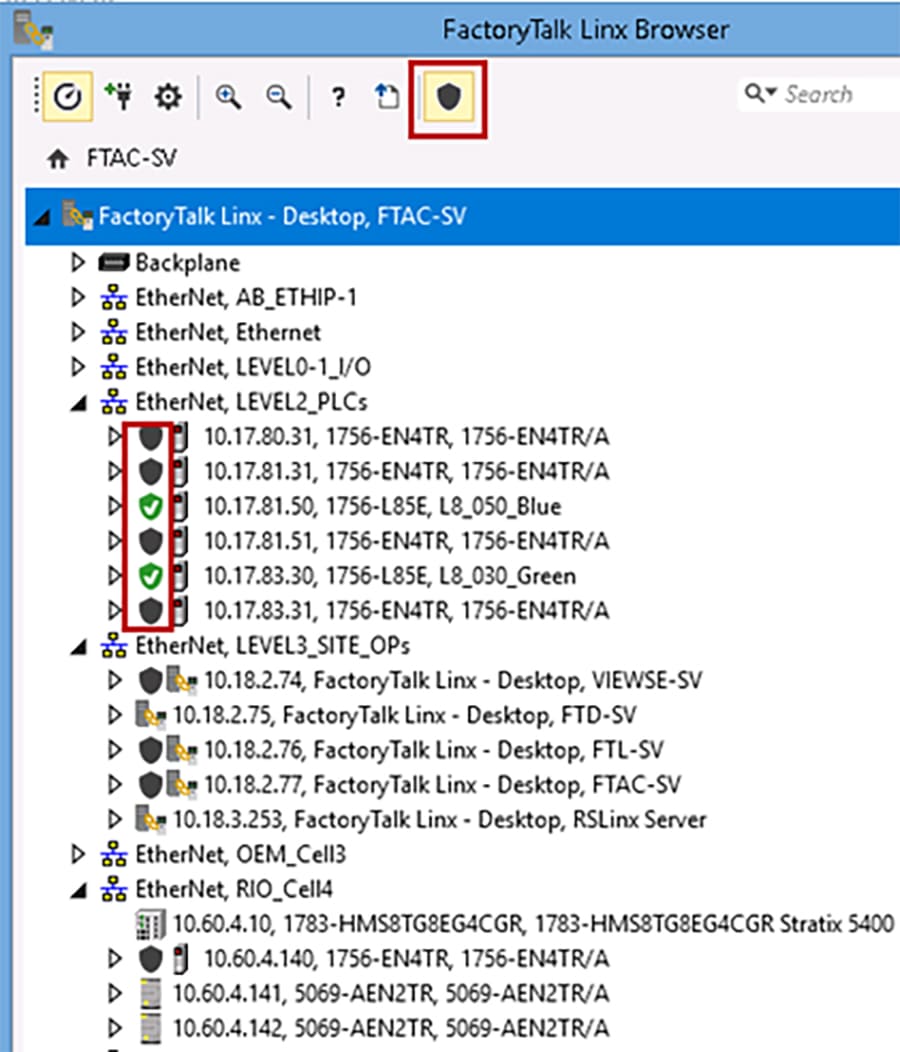
The FactoryTalk Linx Browser utility (Figure 2-4) can be used to view whether CIP Security has been enabled or disabled.
- When a node has a shield icon in front of it, that node supports the CIP Security feature.
- When a node does not have a shield icon in front of it, that node does not support the CIP Security feature.
- When the shield icon is gray, the CIP Security feature is disabled (the default).
- When the shield icon is green, the CIP Security feature has been enabled using the FactoryTalk Policy Manager software.
- When the shield icon is yellow, the CIP Security feature is in the process of applying the configuration pushed down by the FactoryTalk Policy Manager software.
The FactoryTalk Linx browser provides a simple user interface to view and navigate an IACS topology and access IACS device properties. This tool provides a standalone version of the network browser component that is shared by other Rockwell Automation software. This browser will share the FactoryTalk Linx drivers that are configured in the FactoryTalk Administration Console. The FactoryTalk Administration Console permits control system engineers with the ability to add and configure new drivers that can also be used by the Console.
Figure 2-4 FactoryTalk Linx Browser Utility
Note![]() CIP Security IACS devices must be discoverable by FactoryTalk Linx to apply and deploy CIP Security properties. FactoryTalk Linx Browser utility cannot be used to enable/disable the CIP Security properties for products. Use the FactoryTalk Policy Manager software to modify or to enable/disable CIP Security properties on products.
CIP Security IACS devices must be discoverable by FactoryTalk Linx to apply and deploy CIP Security properties. FactoryTalk Linx Browser utility cannot be used to enable/disable the CIP Security properties for products. Use the FactoryTalk Policy Manager software to modify or to enable/disable CIP Security properties on products.
IACS Data Flows
IACS is fed by various upstream and downstream connections that keep it running and provide real-time data to keep systems safe. These north-south traffic flows are typically protected with firewalls securing the network perimeter, however defending the perimeter alone is not enough to help prevent a lateral move. CIP Security properties can assist the industrial security landscape move towards a zero-trust security model by shifting the security perimeter closer the data, limiting the impact of a breach. To successfully apply this concept, it is crucial to understand interactions between IACS devices and manage internal and external data flows. A proper assessment plan should begin with identifying all connections and reviewing the level of risk that they may pose to an IACS ( Table 2-5 ).
- Examine the IACS assets in their information systems and identify information flows that affect the assets.
- Characterize systems and software that are part of the information flow.
- Any connections that pose an unnecessary risk should be reviewed for necessity.
Security is a balance; not every CIP-connected device requires the same level of security, Identify the data with the most critical value. Typically, this is where the most effort to secure data will need to be applied. Also consider there are other industry security standards and regulatory compliance that may be involved, which may be beyond what the organization perceives as the value of any data.
For a successful deployment of CIP Security:
- Validate that all processes or programs are running as expected without CIP Security enabled.
- Identify the types of CIP traffic and data flow that maps to each IACS device or process to the initiator and responder of a CIP connection. Understanding which IACS device initiates a connection and which IACS device accepts the connection will help define conduits for protecting EtherNet/IP communication in different zones. Any EtherNet/IP communication between zones must be through a defined conduit.
Wireshark is a widely-used network protocol analyzer. It is a free and open-source packet analyzer commonly used for network troubleshooting, protocol analysis, software and communications protocol development, and education. The purpose of traffic analysis is to determine who is talking to whom (Figure 2-5).
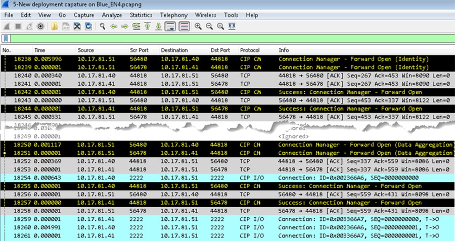
Many IACS devices have a webpage that displays information about the module including the CIP connections established. This is a quick way to determine who is talking to whom. In Figure 2-6 the 1756-EN4TR module with IP Address 10.17.81.51 has ESTABLISHED TCP connections on port 44818 for several IACS devices including 10.17.81.40 and 10.17.81.41 shown in the Wireshark screen capture in Figure 2-5.
Figure 2-6 1756-EN4TR Webpage (TCP Connections page)
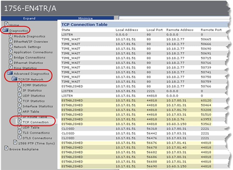
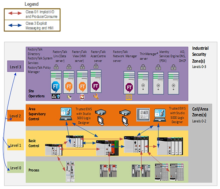
Figure 2-7 illustrates common EtherNet/IP communications in an IACS using the CPwE Model:
- Level 3-Site Operations will typically see CIP class 3 HMI communications to and from IACS devices up to the plant or site-wide FactoryTalk server.
- Level 2-Supervisory Control contains the local management software where engineering workstations (EWS) use CIP class 3 administration communications for uploading/downloading projects to the controllers.
- Level 1-Control System containing the controllers instructing the Level 0 IACS devices and gathering data about a particular process. The following types of traffic can occur at this level includes a combination of CIP class 1 (I/O) and CIP class 3 types of traffic:
–![]() Controllers using CIP class 1 peer-to-peer produced and consumed tags with each other.
Controllers using CIP class 1 peer-to-peer produced and consumed tags with each other.
–![]() Controllers using CIP class 3 messaging for HMI data as well as peer-to-peer MSG instructions.
Controllers using CIP class 3 messaging for HMI data as well as peer-to-peer MSG instructions.
- Level 0-Process containing the sensors, actuators, drives, and robots performing the functions of the process. The following types of traffic that can occur at this level includes:
–![]() Controllers using CIP class 1 I/O connections with I/O and device IACS devices.
Controllers using CIP class 1 I/O connections with I/O and device IACS devices.
–![]() Controllers using CIP class 3 MSG instructions to exchange data or configure IACS devices.
Controllers using CIP class 3 MSG instructions to exchange data or configure IACS devices.
Note![]() For details on EtherNet/IP communications, see EtherNet/IP Overview.
For details on EtherNet/IP communications, see EtherNet/IP Overview.
Figure 2-7 Topology of CIP Connections
IACS Threats and Countermeasures
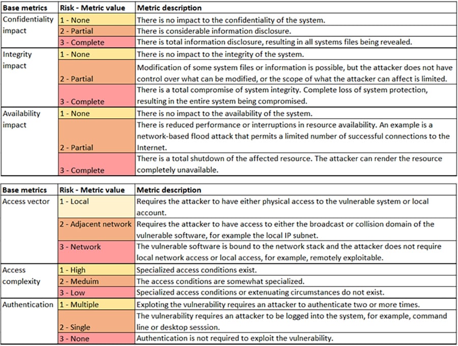
For each asset, identify how and where to enforce the policy that governs the asset. Based on the type of protections for the asset, examine the information flows, systems characterizations, and enforcement mechanisms. Identify potential threats (such as threats to confidentiality, threats to integrity, and threats to availability). A common system used for categorization of threats is the Microsoft-developed STRIDE model ( Table 2-6 ).
- S poofing of user identify
- T ampering
- R epudiation
- I nformation disclosure (privacy breach or data leak)
- D enial of Service (DoS)
- E levation of privilege
The ability of having no proof of an entity performing an action to a system |
||
Unprivileged entity gains privilege access to compromise system |
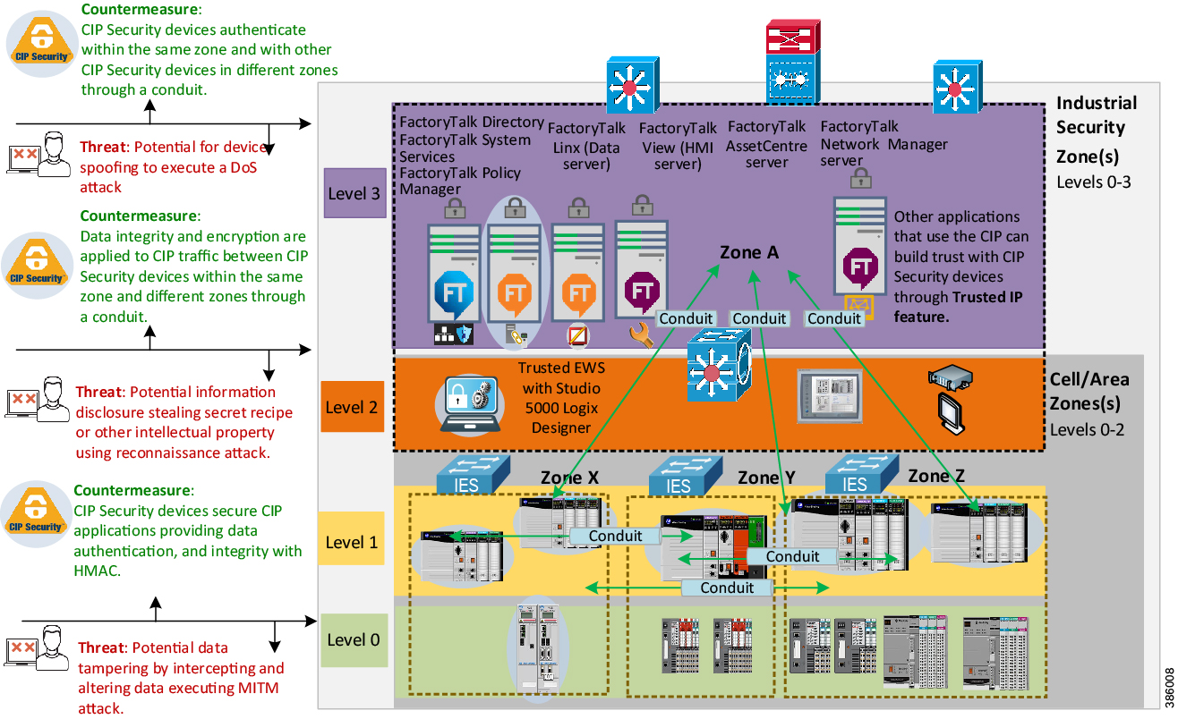
Next, create a network diagram and overlay information, asset locations, data flows, enforcement points, and vulnerability (Figure 2-8). Tools like Microsoft Visio, Excel, or ThreatModeling can be used to create the diagram. Another helpful tool to identify threats is the Common Vulnerabilities and Exposures (CVE). The CVE is a program launched in 1999 by MITRE, a nonprofit that operates research and development centers sponsored by the federal government to identify and catalog vulnerabilities in software or firmware into a free list for organizations to improve their security. For more information, see:
https://cve.mitre.org/
Figure 2-8 Network Overlay of Vulnerability and Countermeasure Enforcement Points
Note Rockwell Automation IACS devices supporting CIP Security include the following:
- ControlLogix 5580 controllers starting with version 32 or higher (GuardLogix controllers do not support CIP Security.)
(In ControlLogix/GuardLogix 5570-based systems, retrofit the latest CIP Security enabled 1756-EN4TR communication module to secure EtherNet/IP communications.)
- 1756-EN4TR communication module
- Kinetix 5700 servo drives starting with firmware version 11.xx or higher
- FactoryTalk Linx starting with version 6.11 or higher
For a more information on Rockwell Automation products and software that supports CIP Security listed above see Table 2-3 .
To see if an IACS device supports CIP Security, refer to the specific vendor IACS device user manual, technical specification, or release notes publications.
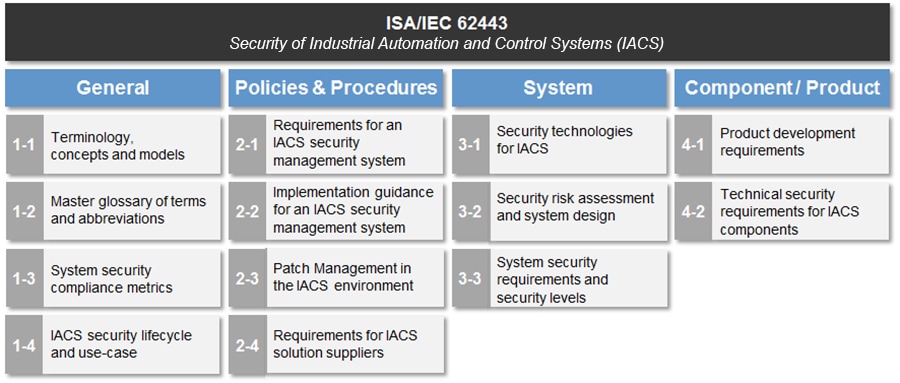
Alignment with ISA/IEC 62443
The ISA/IEC 62443 series of standards, developed by the ISA99 committee and adopted by the International Electrotechnical Commission (IEC), provides a flexible framework to address and mitigate current and future security vulnerabilities in IACS networks. By aligning CPwE CIP Security with ISA/IEC 62443, Cisco, Panduit, and Rockwell Automation have committed to following global industrial security best practices based on defense-in-depth.
This section is an overview of the ISA/IEC 62443-3-2 and 3-3 groups in the series which deal with System Security Requirements and Security Levels (SL) (Figure 2-9).
- 62443-3-2 addresses security risk assessment and system design for IACS. This standard is primarily directed at asset owners or end users.
- 62443-3-3 provides the foundation for assessing the security levels provided by an IACS. The principle audience include suppliers of industrial automation and control systems, system integrators, and asset owners.
Figure 2-9 ISA/IEC 62443 Series of IACS Standards
ISA/IEC 62443-3-2 Overview
Zones and Conduits
The CIP Security architecture is based on logical segmentation with zone and conduits following the ISA/IEC 62443-3-2 Zones and Conduits model.
- Zones create smaller domains of trust to help protect the IACS network from the known and unknown risks in the network.
–![]() IACS devices are identified and grouped in zones according to a common functionality and security requirements. This can be a combination of CIP Security capable IACS devices and ones that are not.
IACS devices are identified and grouped in zones according to a common functionality and security requirements. This can be a combination of CIP Security capable IACS devices and ones that are not.
- Conduits control access to and from different zones. Any EtherNet/IP communication between zones must be through a defined conduit. Conduits can be defined using the following properties:
–![]() The communication technologies being used.
The communication technologies being used.
–![]() The security properties it needs to provide to its connected zones.
The security properties it needs to provide to its connected zones.
Risk Assessment
As part of the ISA/IEC 62443-3-2, the security risk assessment process can be used to assign security levels to zones and conduits. An assessment provides a picture of the organization’s current security posture (current risk state) and what mitigation techniques are needed to get to a preferred state or acceptable risk state. It is recommended to form a multi-discipline team of operations, engineering, IT, and safety representatives to collaborate in the development and deployment of your industrial security policy. Proactively controlling interactions between IACS devices and managing internal and external data flows will help reduce security risks.
Key deliverables for a security assessment include:
- Inventory of authorized and unauthorized devices and software
- Detailed observation and documentation of system performance
- Identification of tolerance thresholds and risk/vulnerability indications
- Prioritization of each vulnerability based on impact and exploitation potential
- Mitigation techniques required to bring an operation to an acceptable risk state
Government entities including the U.S. Department of Homeland Security (DHS) and the U.S. Department of Commerce/National Institute of Standards and Technology (NIST) also reference ISA/IEC 62443 to help with recommendations for conducting security risk assessments. Figure 2-10 shows examples of security risk assessments from DHS.
Figure 2-10 Security Risk Assessment
For additional guidance on methods and approach for risk and vulnerability assessments see:
- Cyber Resilience Review (CRR): Method Description and Self-Assessment User Guide Department of Homeland Security (DHS):
https://www.us-cert.gov/sites/default/files/c3vp/csc-crr-method-description-and-user-guide.pdf - NIST Special Publication 800-82 Revision 2: Guide to Industrial Control Systems (ICS) Security:
https://nvlpubs.nist.gov/nistpubs/SpecialPublications/NIST.SP.800-82r2.pdf
Security Levels
Designing security into an IACS and establishing repeatable standards across multiple plant-wide or site-wide IACS is a long-term goal. When it comes to new designs (greenfield) or redesigns (brownfield) security lifecycle can be used to streamline the process to achieve this goal. The security lifecycle can be categorized into the following three levels:
- Achieved Security Level (SL-A) —The actual level of security for an IACS zone.
- Target Security Level (SL-T) —The desired level of security for an IACS zone.
- Capability Security Level (SL-C) —The level where a particular IACS zone or component is capable of meeting the security level (SL) rating without additional compensating controls when properly configured and integrated.
With all the necessary assessments completed, develop the SL-T for an IACS zone. During the designing of the IACS zone, select components with the capabilities (SL-C) to meet the requirements of the SL-T. Once the IACS zone is operational, the actual security level can be considered as SL-A. The SL-A can potentially be higher if implemented correctly or lower if implemented incorrectly.
Security levels (SLs) represent a method of defining the level of capabilities to address security for a zone or conduit. It is analogous to the concept of Safety Integrity Levels (SILs) for a safety system. SIL is the measure of the safety of a given process. It provides a way to rate the confidence with which a system can be expected to perform its safety function under normal operation. Though it can yield a similar quantitative result, SLs need to be viewed in their own applicable context. SLs ( Table 2-7 ) are based on combinations of likelihood of a threat event occurrence and an estimated adverse impact on industrial operations. SLs can be used to determine the required level of security for zones and conduits.
SL concepts can be used to select the IACS devices and countermeasures to be used within a zone and provide the ability to categorize risks for zone or conduits. The Component Requirements (CR) describe the requirements that must be met by secured industrial components. With CR, IACS devices can be assigned a SL value based on its security capabilities. If certain legacy IACS devices do not satisfy a specific CR of the overall zone or System Requirement (SR), then additional security measures should be taken as described in the defense-in-depth concept.
ISA/IEC 62443-3-3 Overview
Foundational Requirements (FRs)
SLs are based on the seven Foundational Requirements (FRs) for security. FRs are accepted security practices interpreted to fit safely and effectively into a control system design, applying a secure development lifecycle process. These fundamental concepts are carefully adapted to address the unique circumstances of security in control systems such as:
- Risks of economic loss
- Environmental damage to personnel injury and death
- Continuous compliance with the physics associated with distributed control of physical objects
- Processes such as casualties of effects of cyber and physical events occurring in physical processes.
The ISA/IEC 62443-3-3 System Security Requirements directly supports the defense-in-depth approach through its seven Foundational Requirements (FR) for securing an IACS:
- FR1: Identification and authentication control (IAC)
- FR2: Use control (UC)
- FR3: System integrity (SI)
- FR4: Data confidentiality (DC)
- FR5: Restricted data flow (RDF)
- FR6: Timely response to events (TRE)
- FR7: Resource availability (RA)
FRs specify security capabilities that enable a component to mitigate threats for a given security level. FRs include a series of Security Requirements (SRs) describing a number of layered security mechanisms as a baseline. To achieve a specific SL-A value, a system may be required to demonstrate expected outcomes for specific SRs in their respective FRs.
Below are examples of positioning security mechanisms within an IACS network. It includes network segmentation (zones and conduits), technologies like CIP Security, and other management software to be used as building blocks to help bring organizations closer to the desired security level.
FR1: Identification and authentication control (IAC) basic security requires the capability of identifying and authenticating all users (humans, software processes, and devices) before allowing them to access to the IACS system.
- FactoryTalk Security polices and its integration with Microsoft® Active Directory technology can be used to provide centralized management of human access control to the FactoryTalk software utilizing password-based authentication.
–![]() The expected outcome is the ability to manage human user access to Studio 5000 Logix Designer, the configuration tool used for configuring ControlLogix 5580 IACS devices within the IACS network.
The expected outcome is the ability to manage human user access to Studio 5000 Logix Designer, the configuration tool used for configuring ControlLogix 5580 IACS devices within the IACS network.
- The CIP Security device identity and authentication property utilize a commonly accepted Public Key Infrastructure (PKI) to distribute digital certificates to help ensure that only trusted EWS with Studio 5000 Logix Designer can access and program trusted IACS controllers within the IACS network.
–![]() The expected outcome is the ability to enforce only trusted controllers can access and communicate with other trusted IACS devices within the IACS network.
The expected outcome is the ability to enforce only trusted controllers can access and communicate with other trusted IACS devices within the IACS network.
FR4: Data confidentiality (DC) basic security requires the capability to achieve the confidentiality of information on communication channels and in data repositories to help prevent unauthorized disclosure whether at rest or in transit.
- The CIP Security data confidentiality (encryption) property uses proven secure encrypted protocols TLS/DTLS and cipher suites Advanced Encryption System (AES) and Secure Hash Standard (SHA).
–![]() The expected outcome is to help achieve protection against eavesdropping and unauthorized access of data in transit within the IACS network.
The expected outcome is to help achieve protection against eavesdropping and unauthorized access of data in transit within the IACS network.
FR5: Restrict data flow (RDF) basic security requires the capability to segment the control system via zones and conduits to limit the unnecessary flow of data.
–![]() The expected outcome is to have a physical and logical segmentation of IACS networks from non-IACS networks.
The expected outcome is to have a physical and logical segmentation of IACS networks from non-IACS networks.
- Implement an Industrial Demilitarized Zone (IDMZ) for network segmentation between a trusted network (Industrial Zone) and an untrusted network (Enterprise Zone) with redundant high availability security appliances or firewalls as device conduits enforcing data security policies between zones.
–![]() The expected outcome is to securely allow sharing of IACS data and network services between the two zones without any direct connections to a trusted network (Industrial Zone).
The expected outcome is to securely allow sharing of IACS data and network services between the two zones without any direct connections to a trusted network (Industrial Zone).
- VLANs, Access Control Lists (ACLs) and Industrial Firewalls (IFWs) provide additional layers of security to help restrict traffic between zones. Managed Stratix IES have the capability of logging and/or sending syslogs to a Security Information and Event Management (SIEM) software.
–![]() The expected outcome with additional layers of security mechanisms for traffic restrictions is the ability to have multiple opportunities to thwart efforts to pivot in the Industrial Zone while getting real-time alerts when violations occur.
The expected outcome with additional layers of security mechanisms for traffic restrictions is the ability to have multiple opportunities to thwart efforts to pivot in the Industrial Zone while getting real-time alerts when violations occur.
–![]() The expected outcome is the ability to create network micro-segmentation, which is a more granular approach helping prevent lateral movement in the network. The ability to proactively control interactions between IACS devices and manage internal and external data flows will help reduce security risks to acceptable level.
The expected outcome is the ability to create network micro-segmentation, which is a more granular approach helping prevent lateral movement in the network. The ability to proactively control interactions between IACS devices and manage internal and external data flows will help reduce security risks to acceptable level.
Technology Considerations
EtherNet/IP Overview
Understanding EtherNet/IP is imperative for a successful CIP Security deployment. One crucial factor before deploying CIP Security in the IACS network is first validating that all processes and programs are running as expected without any CIP Security enabled. Next identify the types of IACS traffic and data flow that maps to each IACS device or process to the initiator and responder of a CIP connection will aid in creating appropriate conduits.
Note![]() CIP Security is the ODVA, Inc. secure extension of CIP. Its security properties cannot be extended to secure communications for other industrial protocols or common Internet protocols.
CIP Security is the ODVA, Inc. secure extension of CIP. Its security properties cannot be extended to secure communications for other industrial protocols or common Internet protocols.
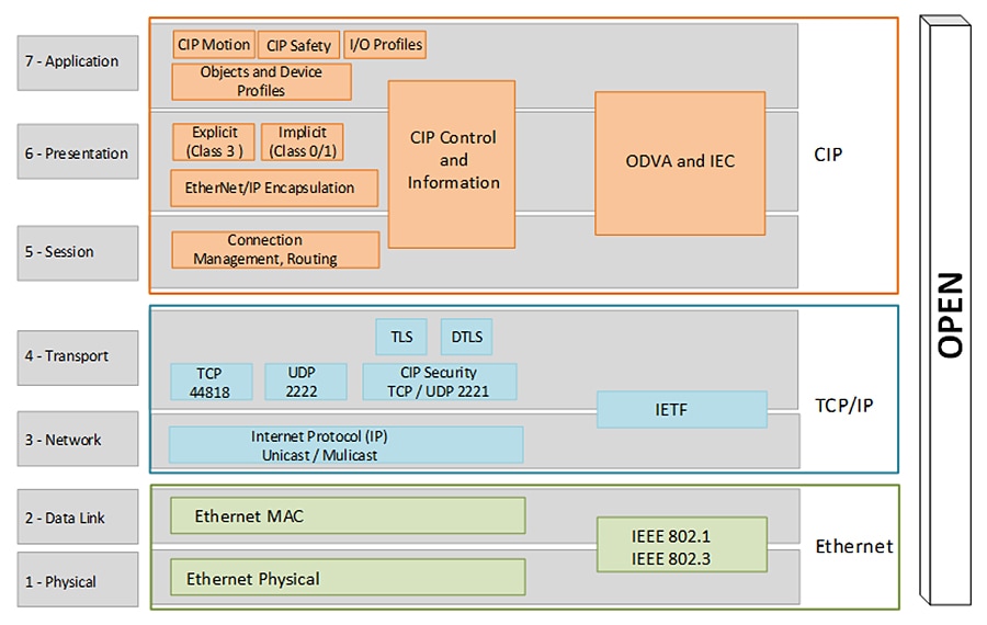
EtherNet/IP (Figure 2-11) is a multi-discipline, control and information platform for use in industrial environments and time-critical applications. The EtherNet/IP network uses standard Ethernet and TCP/IP technologies and an open, application-layer protocol called the Common Industrial Protocol (CIP).
The open, application-layer protocol makes interoperability and interchangeability of industrial automation and control devices on the EtherNet/IP network a reality for real-time control applications.
EtherNet/IP adheres to the following standards:
- IEEE 802.3—Standard Ethernet, Precision Time Protocol (IEEE-1588)
- IETF—Internet Engineering Task Force, standard Internet Protocol (IP)
- IEC—International Electrotechnical Commission
- ODVA, Inc.—Global organization that manages the Common Industrial Protocol (CIP)
Figure 2-11 OSI Model for EtherNet/IP
CIP is a message-based, application-layer protocol. It implements a relative path to send a message from the producing IACS devices in a system to the consuming IACS devices. In a CIP connection, the client will initiate the TCP three-way handshake on port 44818 followed by the connection manager Forward_Open request to the server. The server will reply with a connection manager Success: Forward_Open back to the client.
CIP characterizes two forms of messaging: Explicit Message (Class 3) and Implicit Message (Class 1).
Explicit messaging is when a client IACS device initiates a CIP connection to exchange information with a server IACS device on a specific request (MSG instruction). It uses TCP/IP and requires that the memory location of the information to be sent is also defined in the instruction itself.
- Explicit messages are not time critical and are typically used for data collection.
- They are transferred across TCP/IP and are unscheduled.
- They are unicast frames for one-to-one communications.
- Executing an MSG instruction, a program upload, and HMI communications are examples of explicit connection.
In implicit messaging or I/O connections, the I/O IACS device exchanges data and status with the controller either upon a change of state (COS) or at a requested packet interval (RPI). The RPI is the frequency of updates to the controller based on configuration and location of the input IACS device on the network. The I/O IACS device cannot start sending data until the controller requests for it. The I/O IACS device (server) waits until the controller (client) initiates the TCP connection. Once the TCP and Forward_Open connections have successfully completed, then the I/O IACS device can start sending data with the controller
- Implicit or I/O connections are considered time critical and are scheduled to be produced or consumed at a RPI.
- I/O connections from the producer to the consumer are typically sent as UDP unicast frames, while those sent from the target to the originator can be sent as UDP multicast or unicast frames.
The controller can also produce data for other controllers to consume. The produced and consumed data is accessible by multiple controllers either over the backplane or over the EtherNet/IP network. This data exchange conforms to the producer/consumer model.
For an I/O connection to successfully make a CIP connection, the client will initiate the TCP three-way handshake with the destination port 44818 followed by the connection manager Forward_Open request to the server.
Figure 2-12 is a Wireshark screen capture of initial connections with a client IACS scanner 1756-L8xE (10.17.81.51) and a server IACS adapter 5069-AEN2TR (10.17.81.40). Once the CIP connection is established then I/O data can flow using the UDP port 2222 (Figure 2-13).
Figure 2-12 TCP and CIP Connection
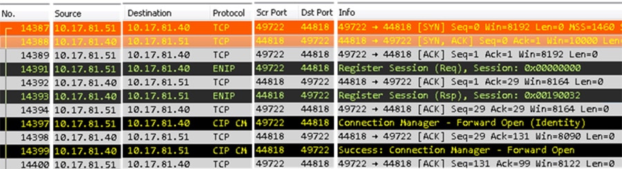
Figure 2-13 UDP I/O Connection
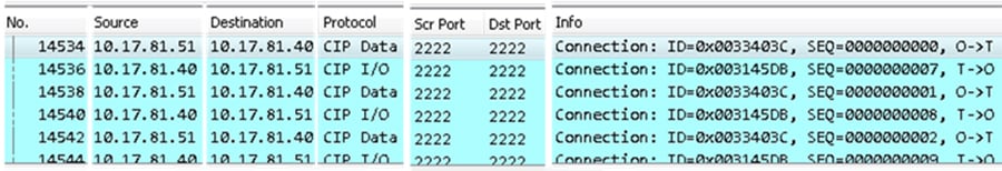
The client is a scanner IACS device 1756-L8xE (10.17.81.51) and the server is an adapter IACS device 5069-AEN2TR (10.17.81.40). First the client will initiate the TCP connection to the server using TCP port 44818. Typically, this is triggered when an I/O device is added to the I/O configuration of a controller.
2.![]() Client <- Server : SYN, ACK
Client <- Server : SYN, ACK
Once the TCP connection has been established, the client will initiate the CIP connection using TCP port 44818 to the server using Connection Manager.
4.![]() Client -> Server: Forward_Open
Client -> Server: Forward_Open
5.![]() Client <- Server : Success: Forward_Open
Client <- Server : Success: Forward_Open
Once the CIP connection has been established, the client and the server will start exchanging data using UDP port 2222.
TLS (RFC 5246) and DTLS (RFC 6347)
Transport Layer Security (TLS) and Datagram Transport Layer Security (DTLS) are both network protocols that allow client/server applications to communicate across a network in a way designed to prevent eavesdropping and tampering. Current TLS versions include TLS 1.1, 1.2 and 1.3. CIP Security implemented in Rockwell Automation IACS devices use TLS version 1.2 on TCP/UDP port of 2221. It uses the TLS/DTLS technology to “wrap” around the industrial traffic creating a secure tunnel allowing the EtherNet/IP traffic to flow through it. This allows for the applications like CIP Motion™ and CIP Safety to continue to work the same regardless of the security layer.
TLS is a proven open security standard already being used to minimize potential vulnerabilities in common applications including web browsers, instant messaging, email, and voice over IP in the Enterprise Security Zone. TLS provides three primary services that help ensure the safety and security of data exchanged:
DTLS is based on TLS, but is specifically used for UDP connections instead of TCP connections. Since DTLS is based on TLS, it can use a majority of the cipher suites described for TLS.
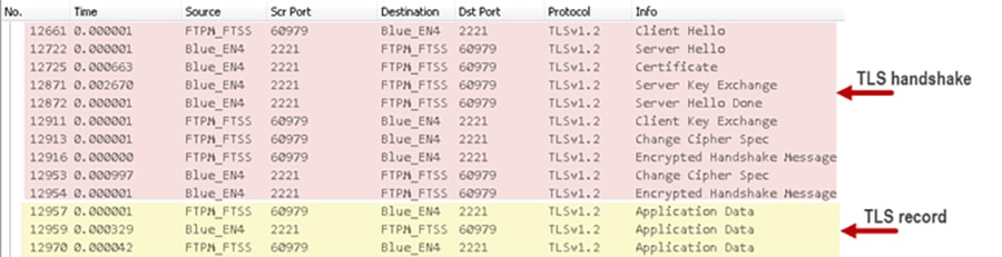
Two key protocols work together to provide connection security in the TLS operation (Figure 2-14):
1.![]() The TLS handshake protocol is performed only once to establish a secure connection for both communicating parties. It establishes the following:
The TLS handshake protocol is performed only once to establish a secure connection for both communicating parties. It establishes the following:
a.![]() Both will negotiate the secure communication’s cipher suite (a cipher suite is the collection of cryptographic algorithms that will be used in subsequent phase below).
Both will negotiate the secure communication’s cipher suite (a cipher suite is the collection of cryptographic algorithms that will be used in subsequent phase below).
b.![]() The root certificate is presented as authentication as the trust anchor from which the whole chain of trust is derived.
The root certificate is presented as authentication as the trust anchor from which the whole chain of trust is derived.
c.![]() The negotiation of the shared (secret) session key is generated then encrypted and sent to the other communicating party for use by the TLS record protocol. The shared (secret) session key is based on the asymmetric public-private key pair from the certificate.
The negotiation of the shared (secret) session key is generated then encrypted and sent to the other communicating party for use by the TLS record protocol. The shared (secret) session key is based on the asymmetric public-private key pair from the certificate.
2.![]() After the TLS handshake protocol is complete, the TLS record protocol begins. From this point, the TLS record protocol is responsible for getting the data from applications, fragmenting it to an appropriate size, applying the shared (secret) session key to secure and verify data integrity, then sends it to the network transport layer (TCP/UDP). Optionally, the application data exchange can also use the shared (secret) session key for symmetric encryption of the data. In symmetric encryption, the exact same key is used on both sides of a conversation for both encrypting and decrypting. An example of symmetric algorithm used for encryption is AES 128-bit encryption.
After the TLS handshake protocol is complete, the TLS record protocol begins. From this point, the TLS record protocol is responsible for getting the data from applications, fragmenting it to an appropriate size, applying the shared (secret) session key to secure and verify data integrity, then sends it to the network transport layer (TCP/UDP). Optionally, the application data exchange can also use the shared (secret) session key for symmetric encryption of the data. In symmetric encryption, the exact same key is used on both sides of a conversation for both encrypting and decrypting. An example of symmetric algorithm used for encryption is AES 128-bit encryption.
Figure 2-14 TLS Handshake and Record Layers
X.509 Certificate Authentication
X.509 is a key component in the TLS/DTLS protocol. In the X.509 certificate structure, a root certificate is used as the trust anchor from which the whole chain of trust is derived; therefore a trust anchor must be in the possession of the trusting party beforehand to make any further certificate path validation possible. Rockwell Automation IACS devices used a vendor certificate as a root certificate including the unique key pair installed in the IACS device at the time of manufacture to provide device authenticity based on the X.509 standard.
The IACS device vendor certificate is presented as the server certificate with the public key during the TLS handshake to provide IACS device authenticity to the root-level CA (FactoryTalk System Services) but is not used as a basis for trust while being configured with new trust anchors and client certificates. By default, CIP Security IACS devices are configured to trust any commissioning tool that connects to it and configures the security settings. This is called the Trust On First Use (TOFU) model. It is a security model in which a client needs to create a trust relationship with an unknown server. TOFU concept used by SSH programs, where the public key of the peer is not verified, or verified in an out-of-bound way.
Once security properties are configured in zones and conduits in the FactoryTalk Policy Manager commissioning tool and deployed, trust between IACS devices is limited to the new client certificates (digitally signed with the trusted CA's private key) that the tool has provisioned, and the vendor certificate becomes irrelevant.
It is recommended to secure the root-level CA for protection of the signing keys. If the root CA were to be exploited, the security breach would compromise all IACS devices configured within the FactoryTalk system. Here are some security best practices for securing CAs:
–![]() Hardware Security Module (HSM) to help protect the Private Key of the CA. HSMs can either be network attached through a private network to the CA, commonly used in virtualized CAs, or can be directly attached to the CA.
Hardware Security Module (HSM) to help protect the Private Key of the CA. HSMs can either be network attached through a private network to the CA, commonly used in virtualized CAs, or can be directly attached to the CA.
–![]() Install in a physically secure environment, which will help protect the Root CA.
Install in a physically secure environment, which will help protect the Root CA.
–![]() Access to the CAs should be limited only to the CA administrator of the PKI hierarchy.
Access to the CAs should be limited only to the CA administrator of the PKI hierarchy.
–![]() It is recommended to disable remote access technologies to the CAs such as Remote Desktop Protocol (RDP).
It is recommended to disable remote access technologies to the CAs such as Remote Desktop Protocol (RDP).
–![]() Disable CD-ROM auto play and USB ports either in the BIOS or in the virtual machine settings.
Disable CD-ROM auto play and USB ports either in the BIOS or in the virtual machine settings.
–![]() Keep the CA disconnected to the Internet unless you are performing maintenance tasks.
Keep the CA disconnected to the Internet unless you are performing maintenance tasks.
–![]() Increase the amount of system logging to support audit requirements.
Increase the amount of system logging to support audit requirements.
–![]() CA retrieval should be documented and audited, generally referred to, as a chain of custody.
CA retrieval should be documented and audited, generally referred to, as a chain of custody.
–![]() It is recommended not to reuse the computer hosting the Network FactoryTalk Directory (FTD) and FactoryTalk System Services for other applications.
It is recommended not to reuse the computer hosting the Network FactoryTalk Directory (FTD) and FactoryTalk System Services for other applications.
CIP Security Properties
CIP Security defines the concept of Security Profiles. A Security Profile is a set of well-defined capabilities to facilitate device interoperability and end user selection of devices with the appropriate security capability. This section details the key security properties in the EtherNet/IP Confidentiality Profile implemented to mitigate threats.
The EtherNet/IP Confidentiality Profile leverages the open security IETF-standard TLS (RFC 5246) and DTLS (RFC 6347) protocols to help provide the following CIP Security properties:
- Device identity and authentication —Aids EtherNet/IP IACS devices in building trust by allowing each to provide identity through certificate exchange or pre-shared keys.
- Data integrity and authentication —Helps ensure the data has not been tampered with or falsified while in transit with TLS Hash-based Message Authentication Code (HMAC).
- Data confidentiality (encryption) —Increase the overall IACS device security posture, message encryption can be enabled to avert unwanted data reading and disclosure.
In addition to CIP Security properties, Rockwell Automation IACS devices currently supporting CIP Security also include the following features:
- Centralized System Management —The FactoryTalk Policy Manager software is the commissioning tool used to easily create and deploy security policies to many IACS devices at once.
- Micro-segmentation —CIP Security is enforced at the IACS device and CIP application level, allowing segmentation to be applied at the actual IACS device and data.
- Disable HTTP port —Rockwell Automation products that support CIP Security can enable or disable the unsecure HTTP port/protocol of IACS devices in an IACS application.
- Legacy system support —Rockwell Automation IACS devices that support CIP Security options with legacy IACS devices:
–![]() Trusted IP Conduits can be created to authorize EtherNet/IP communication originating from an IACS device that does not support CIP Security to one that does based on IP address.
Trusted IP Conduits can be created to authorize EtherNet/IP communication originating from an IACS device that does not support CIP Security to one that does based on IP address.
–![]() Retrofitting ControlLogix 5570-based applications with the latest CIP Security enabled 1756-EN4TR communication module to secure EtherNet/IP communications.
Retrofitting ControlLogix 5570-based applications with the latest CIP Security enabled 1756-EN4TR communication module to secure EtherNet/IP communications.
Note![]() Once CIP Security capable IACS devices are configured and deployed with security properties, RSLinx® Classic cannot browse and discover those IACS devices unless a Trusted IP conduit is configured and deployed. FactoryTalk Linx version 6.11 or higher supports CIP Security and must be used to browse, discover, and go online with IACS devices.
Once CIP Security capable IACS devices are configured and deployed with security properties, RSLinx® Classic cannot browse and discover those IACS devices unless a Trusted IP conduit is configured and deployed. FactoryTalk Linx version 6.11 or higher supports CIP Security and must be used to browse, discover, and go online with IACS devices.
Device Identification and Authentication
IACS device spoofing can occur when a malicious device poses as a legitimate IACS device to send messages with the intent to disrupt operations, thus successfully executing a DoS attack. These types of attacks can render the IACS device inoperable. With the CIP Security device identification and authentication property, communicating entities must provide some information about themselves that is trustworthy and verifiable before data is exchanged.
The CIP Security device identification and authentication property is used to establish and build IACS device trust with the following methods:
- Pre-Shared keys (PSK) are used to provide identity based on keys shared in advance among the communicating parties. This represents a more manual method of authentication and typically implemented in small systems. Optionally, the previously shared keys between two parties can be used for encryption and decryption of data.
The PSK handshake does not require any certificate parsing and signature verification providing less performance impact on establishing connections, however, the throughput performance is roughly the same as using certificates. PSK can be used to obtain all three security properties: device identification and authentication, data integrity, authentication, and/or data confidentiality for IACS device within the same zone (intra-zone communication) security.
PSK are generally considered less secure than a certificate just like in human-user passwords, VPN, and Wi-Fi authentications, it may be subject to brute-force and dictionary attacks to learn the PSK. Recovering a compromised PSK is difficult because there is no mechanism to notify IACS devices of a key compromise, except by pushing a new key pair to all IACS devices. An additional limitation with PSK is IACS devices can only ever have one PSK configured, as a result, any conduits required between zones (inter-zone communication) configured with pre-shared key can only use Trusted IP.
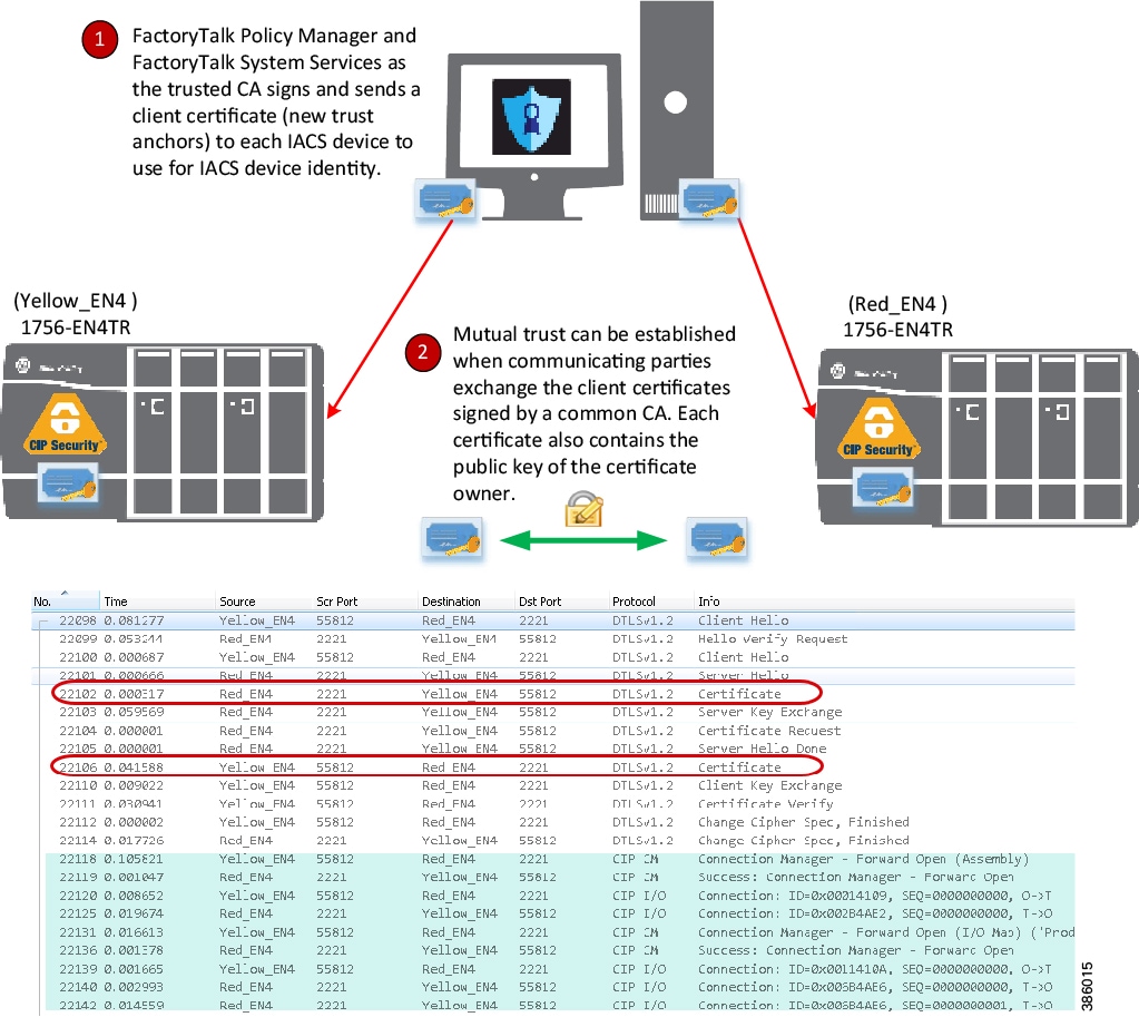
- Certificates are agreements between communicating parties and a common entity called a Certificate Authority (CA). The CA is a trusted entity that manages and issues security certificates to requesters to prove their identities and public keys that are used for secure communication in an IACS network. Mutual trust is established when communicating parties exchange certificates signed by a common CA. (Figure 2-15). Once the TLS handshake completes and CIP application data exchange begins, there are no public key or certificates involved only symmetric encryption of AES and HMAC with SHA.
Certificates can be used to obtain all three security properties: device identification and authentication, data integrity and authentication, and/or data confidentiality for IACS device within the same zone or different zones security. It provides a higher level of complexity in authentication as the key length may be larger than a PSK. The key length in encryption determines the feasibility of performing a brute-force attack, with longer keys exponentially more difficult to crack than shorter ones. It scales well to larger systems and is easier to maintain as devices get introduced to the network.
Considerations to using certificates:
It is recommended to secure the root-level CA for protection of the signing keys. If the root CA were to be exploited, the security breach would compromise all IACS devices configured within the FactoryTalk system.
FactoryTalk Policy Manager is the commissioning tool graphical user-interface (GUI) used to configure, deploy, and view the system communication security policies.
FactoryTalk System Services is the root-level CA. It is the service that signs and issues client certificates to give assurance for a communicating party’s authenticity. It runs as a service in the background to help enable the deployment of CIP Security policies configured in the FactoryTalk Policy Manager commissioning tool.
Figure 2-15 Device Identification and Authentication (Client Certificate Example)
Note In the release of CIP Security, it is required to install FactoryTalk System Services and FactoryTalk Policy Manager software on the computer that hosts the FactoryTalk Network Directory.
For more details see: Additional Resources.
Data Integrity and Authentication
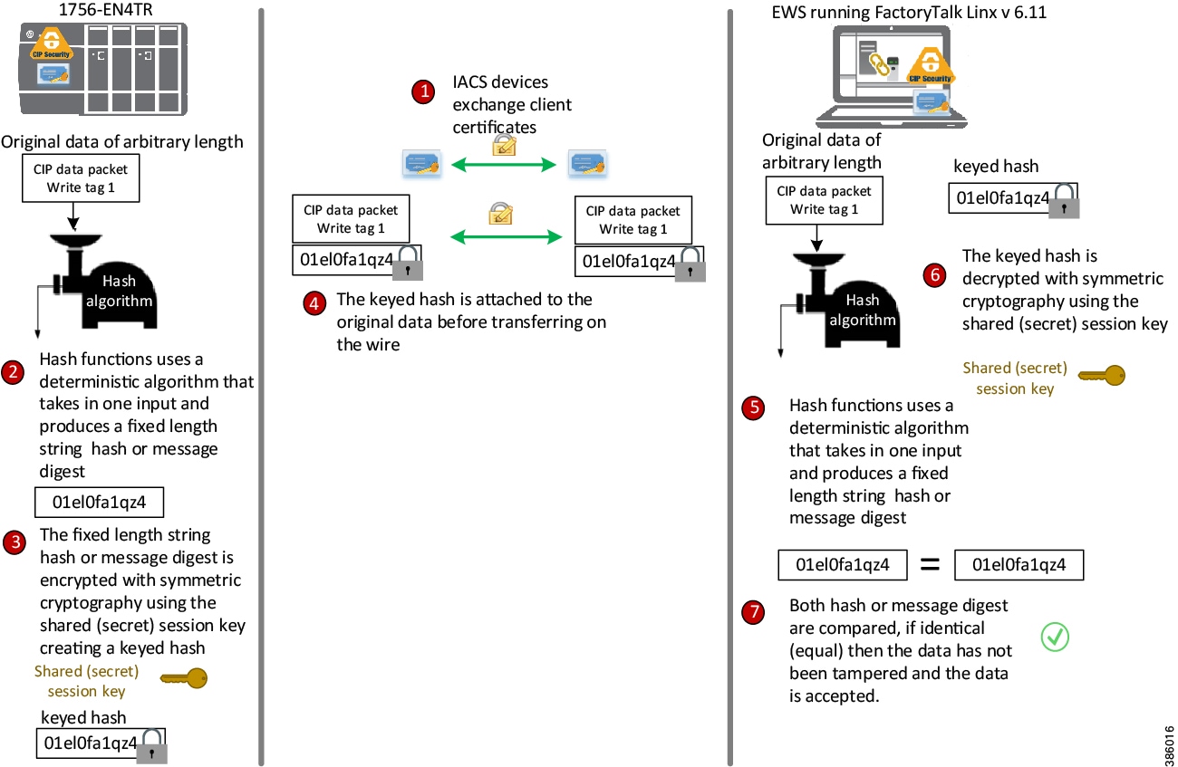
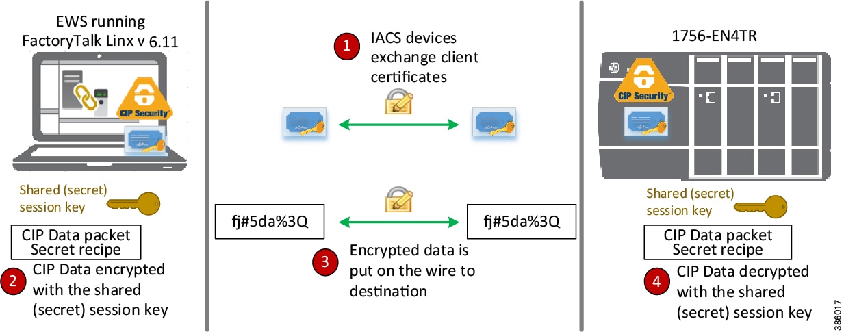
Data in transit can be intercepted, allowing for sensitive information such as secret recipes to be stolen. Even worse, data tampering by way of unauthorized changes to configuration, programs, commands, or alarming may cause personnel to initiate incorrect actions leading to a number of undesirable events, such as equipment damage, operation unavailability, endangering human life, and environmental impacts. CIP Security enables the sender’s IACS device to calculate a keyed hash before transit to send along with the original message.
Hash functions use a deterministic algorithm that takes in one input and produces a fixed-length string every time; therefore, using the same input will always result in the same output. The fixed-length string is then encrypted with a shared (secret) session key to create a keyed hash or HMAC (keyed-Hash Message Authentication Code) to achieve integrity and authenticity of the message. Once the receiver IACS device gets the message, it can run the hash algorithm and compare the output with the keyed hash received. If both keyed hashes are identical, it means that the message has not tampered with and the data is accepted. (Figure 2-16).
Figure 2-16 Data Integrity and Authentication (HMAC Example)
Note![]() CIP Security data integrity use cases are specific to data in transit and not data at rest. Once the CIP packet is on the wire is where CIP Security comes into play to help ensure data is not altered.
CIP Security data integrity use cases are specific to data in transit and not data at rest. Once the CIP packet is on the wire is where CIP Security comes into play to help ensure data is not altered.
Data Confidentiality (Encryption)
Data sent over a wire can be intercepted allowing for sensitive information such as account credentials, secret recipes, or intellectual property to be stolen. CIP Security employs encryption to help reinforce confidentiality by helping to protect any sensitive or classified information from being stolen.
After the TLS handshake is complete and the session begins. The communicating IACS devices will use a shared (secret) session key to encrypt and decrypt the CIP application data sent to each other. The shared (secret) session key uses symmetric encryption, where the exact same key is used on both sides of a conversation, for both encrypting and decrypting. An example of symmetric algorithm used for encryption is Advanced Encryption System (AES) 128-bit encryption (Figure 2-17).
Encryption can be used to help reinforce confidentiality by helping to protect any sensitive or classified information from being read or stolen. The CIP Security confidentiality property uses symmetric encryption for the IACS application data exchange. This type of encryption is much less computationally intensive than asymmetric cryptography, which is only used for the TLS handshake or initial establishing of the connection.
Considerations to data confidentiality:
The data confidentiality security property is optional as data encryption will impact IACS device performance. Situations exist where a customer makes a reasonable design decision that allows for more risk acceptance to trade for better performance. For zones where network communication does not require the level of security for data encryption, for CIP Motion applications, and I/O connections; Rockwell Automation, Cisco, and Panduit recommend enabling only device and data authentication/integrity without encryption.
Note![]() CIP Motion application was not tested or validated as part of CPwE CIP Security. See the specific vendor IACS device technical specification or release notes publications for performance and capacity.
CIP Motion application was not tested or validated as part of CPwE CIP Security. See the specific vendor IACS device technical specification or release notes publications for performance and capacity.
Figure 2-17 Data Confidentiality (Encryption)
Note![]() Rockwell Automation devices and software currently supporting CIP Security can enable data confidentiality (encryption) as an optional policy.
Rockwell Automation devices and software currently supporting CIP Security can enable data confidentiality (encryption) as an optional policy.
Trusted IP Communication
Rockwell Automation devices and software currently supporting CIP Security are still able to interoperate with devices that do not support CIP Security on the same network by using the Trusted IP feature. The feature can be implemented to authorize CIP communication between an IACS device that is capable of CIP Security and one that is not based on IP address.
Trusted IP helps add control on access for legacy IACS and third-party CIP applications where standards and policies are needed for audit or compliance purposes.
With Trusted IP conduits, there are no mechanisms for device or data identity and authentication or data encryption. Trusted IP feature is essentially a list of IP addresses for known trusted IACS devices or administrator approved CIP applications allowed to access and communicate with CIP Security capable IACS devices.
IACS devices currently supporting CIP Security are still able to interoperate with IACS devices that do not support CIP Security on the network through the standard TCP/UDP ports of 44818 and 2222 depending on which IACS device is initiating the CIP connection.
No additional configuration for a Trusted IP conduit is required in FactoryTalk Policy Manager to allow the EtherNet/IP communication, if the initiator of the CIP connection is from a CIP Security capable IACS device to one that is not or when the IACS devices are placed in the same zone.
A Trusted IP conduit configuration is required in FactoryTalk Policy Manager to allow EtherNet/IP communication between devices in different zones or if the initiator of the CIP connection is from an IACS device with no CIP Security capabilities to one that is capable.
In Figure 2-18, the FactoryTalk Network Manager software does not support CIP Security, however is able to initiate a CIP scan to discover the 1756-EN4TR, which does support CIP Security through the Trusted IP feature.
Figure 2-18 Trusted IP Feature
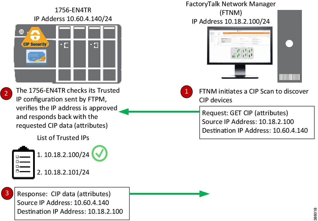
Note![]() In FactoryTalk Policy Manager, the authentication method of a Trusted IP can be defined on a conduit to allow authorized CIP connections between a CIP Security capable IACS device and one that is not.
In FactoryTalk Policy Manager, the authentication method of a Trusted IP can be defined on a conduit to allow authorized CIP connections between a CIP Security capable IACS device and one that is not.
CIP Security Limitations
The following are limitations and considerations of the solution from Rockwell Automation to implement CIP Security in an IACS:
CIP Bridging
CIP Security cannot be configured or apply protection through a CIP bridge or controller backplane. In Figure 2-19, CIP Security can be applied to the 1756-EN4TR in slot 0, but cannot be applied to the 1756-EN4TR in slot 4 or to the IACS devices in the DLR off of the 1756-EN4TR in slot 4.
Optionally, ControlLogix has a feature called Trusted slot, which can be configured to maintain network segmentation on the local chassis. This feature is not part of CIP Security but native to ControlLogix and can be found on the controller Properties Security tab. The trusted slot feature restricts the communication paths through which certain operations are performed on Logix controllers.
ControlLogix Redundancy Systems (Multicast traffic)
Currently, multicast connections with CIP Security are not supported. As a result, CIP Security cannot be used in a ControlLogix Enhanced Redundancy system or with any CIP multicast applications.
Network Address Translation (NAT)
Note![]() NAT was not tested or validated as part of CPwE CIP Security. Due to the general complexity of NAT configuration, maintenance, and management, careful consideration and testing is recommended before overlaying CIP Security in an architecture with NAT.
NAT was not tested or validated as part of CPwE CIP Security. Due to the general complexity of NAT configuration, maintenance, and management, careful consideration and testing is recommended before overlaying CIP Security in an architecture with NAT.
CIP Security is IP-based, meaning if an IACS device is reachable to the computer/server hosting FactoryTalk Policy Manager and FactoryTalk System Services by IP address, then CIP Security can be successfully deployed to that IACS device. Therefore, Network Address Translation (NAT) can be implemented with CIP Security only if the computer/server with FactoryTalk Policy Manager can access the CIP Security IACS device via an IP address.
Automatic Device Replacement (ADR)
The current workflow for an IACS device requiring ADR with CIP Security implementation is to physically replace the IACS device, apply ADR, then redeploy the CIP Security properties to the IACS device from FactoryTalk Policy Manager.
RSLinx Classic Software
RSLinx Classic software does not support CIP Security and cannot be used implement and deploy CIP Security properties to capable IACS devices. Once CIP Security capable IACS devices are configured and deployed with security properties, RSLinx Classic will not be able to browse and discover those IACS devices unless a Trusted IP conduit is configured and deployed. FactoryTalk Linx version 6.11 or higher supports CIP Security and must be used to browse, discover, and used to go online with IACS devices.
Architectural Considerations
Network Segmentation
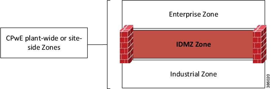
Network segmentation is a practice of zoning the IACS network to create smaller domains of trust to help protect the IACS network from the known and unknown risks in the network. Applying the concepts of defense-in-depth, the Industrial Demilitarized Zone (IDMZ) is the first layer of defense for network segmentation enforcing data security policies between a trusted network (Industrial Zone) and an untrusted network (Enterprise Zone) with redundant high availability security appliances or firewalls. The IDMZ is the network perimeter that acts as a buffer to securely allow sharing of IACS data and network services between the two zones (Figure 2-20).
Figure 2-20 CPwE Plant-wide or Site-wide Zone (IDMZ)
Note Links to the Securely Traversing IACS Data Across the Industrial Demilitarized Zone Design and Implementation Guide are provided for further details.
- Rockwell Automation site:
http://literature.rockwellautomation.com/idc/groups/literature/documents/td/enet-td009_-en-p.pdf - Cisco site:
https://www.cisco.com/c/en/us/td/docs/solutions/Verticals/CPwE/3-5-1/IDMZ/DIG/CPwE_IDMZ_CVD.html
The second layer of defense is grouping IACS devices by VLANs/subnets with access control lists (ACLs). At a high level, subnets and VLANs are analogous in that they both segment the network. The main differentiator between the two are their functions within the communication stack referenced in the Open Systems Interconnection (OSI) model. VLANs are used at the data link layer with Layer 2 MAC addresses, while subnets are used at the network layer with Layer 3 IP addresses. Large IP networks can be further logically-partitioned into multiple, smaller network segments called subnets. A router is put in place as the logical and/or physical boundary between subnets. VLANs are a method of creating logically-independent Layer 2 broadcast domains within a large network interconnected through switches, creating smaller connected LANs (Figure 2-21). By utilizing VLANs, differentiated services can be applied to equipment of common capability.
- Functional/Treatment of traffic—Quality of Service (QoS)
- Scalability/Network performance—Smaller broadcast domains
- Security—Smaller domains of trust reducing attack surface
By default, the routing or inter-vlan routing features typically at the Industrial Zone core and distribution Layer 3 network device will permit all traffic between VLANs. Access Control Lists (ACLs) on the Layer 3 network interfaces can be used to restrict traffic, but are limited in capabilities. The ACLs on Layer 3 network devices such as routers or multi-layer switches are not the same as firewall rules; they may have performance impact on traffic and they can become too complex to manage if too many exceptions are required. Layer 3 ACLs are most effective when they are small and used for explicit denies.
To provide more flexibility and simplicity to network segmentation, Deploying Network Security within a Converged Plantwide Ethernet Architecture Design and Implementation Guide uses Cisco TrustSec (CTS) technology to define access policies using security groups. This allows the segmentation of IACS assets using Security Group Tags (SGT) which group the assets regardless of their location in the plant-wide network.
Benefits of Cisco TrustSec (CTS) include:
- CTS uses tags to represent logical group privilege.
- The tag is called an SGT and is used in access policies.
- The SGT is understood and is used to enforce traffic by certain Cisco and Allen-Bradley Stratix switches, routers, and firewalls.
- CTS is defined in three phases: classification, propagation, and enforcement.
Note See Deploying Network Security within a Converged Plantwide Ethernet Architecture Design and Implementation Guide are provided for further details.
- Rockwell Automation site:
https://literature.rockwellautomation.com/idc/groups/literature/documents/td/enet-td019_-en-p.pd f - Cisco site:
https://www.cisco.com/c/en/us/td/docs/solutions/Verticals/CPwE/5-1/Network_Security/DIG/CPwE-5-1-NetworkSecurity-DIG.html
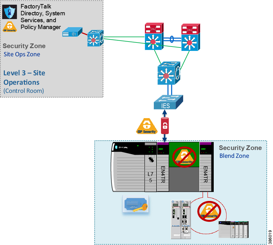
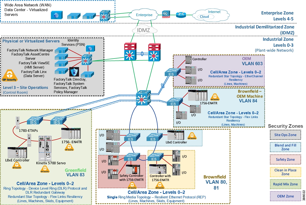
CIP Security provides a third layer of defense enforced at the IACS application and device. It creates a network micro-segmentation, which is a more granular approach by helping prevent lateral movement within a zone or between zones. Micro-segmentation reduces an attacker's capability to easily compromise an entire network. A CIP Security architecture within CPwE is composed of multiple zones, which are IACS devices grouped typically based on operation function and security requirements (Figure 2-22).
For brownfield deployments to meet certain security regulations, an organization may have to reconfigure VLANs and readdress IACS devices to meet zoning efforts. This can be highly disruptive to industrial operations. CIP Security allows for a more cost-effective and reliable approach with the ability to create security zones with applicable security properties with minimal redesign to the existing IACS application.
Figure 2-22 CIP Security Zones
Zones and Conduits
The CIP Security properties to apply in a zone and conduit depends on the requirements identified in the risk assessment and targeted security level. Typically, security properties assigned to zones and conduits can be based on the potential consequences should an attack objective be achieved in that zone. For example, if an operation is interrupted, will it cause financial loss, damage, interruption to the delivery of goods or services essential to the organization’s continued success?
Zones are groups to which IACS devices are added. IACS devices are grouped based on operation function and security requirements. A function implies the concept of an individual system or element within a larger system functioning together. CIP Security properties are applied at the zone level, which can be referred to as Intra-zone security and at the conduit level as Inter-zone security. This allows for device identity and authentication and data integrity between IACS devices in the same zone and in different zones.
- Intra-zone consists of CIP Security properties configured on the individual zone and would apply to all devices and CIP application data within that zone but not between other zones. For example, in Figure 2-22 the 1756-L8xE and 1756-EN4TR are in the same Blend and Fill (blue) Zone and configured to uses certificates as device identity and authentication. Even though the two IACS devices are in the same trusted zone, they are still required to exchange certificates for proof of identity. This also allows for data integrity and authentication within the same zone without having to explicitly create a conduit to one another.
Zones can include a combination of CIP Security capable IACS devices and ones that are not ( Table 2-8 ). IACS devices currently supporting CIP Security are still able to interoperate with IACS devices that do not support CIP Security on the same network through the standard TCP/UDP ports of 44818 and 2222 depending on which IACS device is initiating the CIP connection. IACS devices with CIP Security enabled will use TLS/DTLS version 1.2 on TCP/UDP port of 2221. For additional details, see Trusted IP Communication.
Note![]() For zones where network communication does not require the level of security for data encryption (for example, CIP Motion applications), Rockwell Automation, Cisco, and Panduit recommend enabling only device and data authentication/integrity without encryption. CIP Motion application was not tested or validated as part of CPwE CIP Security.
For zones where network communication does not require the level of security for data encryption (for example, CIP Motion applications), Rockwell Automation, Cisco, and Panduit recommend enabling only device and data authentication/integrity without encryption. CIP Motion application was not tested or validated as part of CPwE CIP Security.
|
||
|
3.For a list of the catalog numbers with the associated firmware versions that currently support CIP Security, see System Components. |
- Inter-zone consists of CIP Security properties configured on the individual conduit and would apply to CIP application data traversing between different zones. For example, in Figure 2-23 for FactoryTalk applications defined in the Site Ops Zone (gray) to securely exchange EtherNet/IP data with the Levels 0 - 2 Cell/Area Zones containing CIP Security IACS devices, a conduit must be explicitly configured with the desired security properties from the Site Ops Zone (gray) to each of the following zones:
–![]() Clean in Place Zone (yellow)
Clean in Place Zone (yellow)
Figure 2-23 Inter-Zone Security
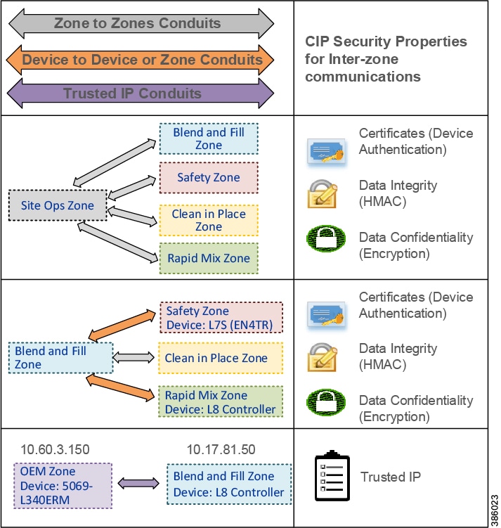
Conduits are used to control access and trusted communication to and from different zones. Any communication between zones must be explicitly configured through a defined conduit. To manage and control communication between zones, conduits can be created and removed as needed on a device-to-device and zone-to-zone basis. This is not a new concept; VPNs are conduits creating a secure tunnel from a source to a destination using negotiated cipher suites.
Types of CIP Security Conduits include:
- Zone to Zone Conduits—This type of conduit is useful for centralized zones like the Level 3-Site Operations and Level 2-Supervisory controls where communications are exchanged to and from the plant-wide or site-wide IACS devices.
- Device to Device Conduit—This type of conduit is useful in situations where certain IACS device control to an operation is identified more critical therefore strict controlled access must be applied with higher security than the other IACS in the same zone.
- Device to Zone Conduit—This type of conduit is useful when controlled access from a single IACS device in a particular zone is required to a group of IACS in another zone.
- Trusted IP Conduit—This type of conduit can be used for CIP connections initiated from legacy IACS devices, third-party applications, or OEM machines that do not support the CIP Security technology to ones that do support it. For example, in Figure 2-23 a Trusted IP conduit must be defined and explicitly created for the OEM Zone CompactLogix 5380 (5069-L340ERM) to send an MSG to the Blend and Fill Zone ControlLogix 5580 (1756-L85E).
Note![]() Once CIP Security capable IACS devices are configured and deployed with security properties, RSLinx Classic will not be able to browse and discover those IACS devices unless a Trusted IP conduit is configured and deployed. FactoryTalk Linx version 6.11 or higher supports CIP Security and must be used to browse and discover IACS devices.
Once CIP Security capable IACS devices are configured and deployed with security properties, RSLinx Classic will not be able to browse and discover those IACS devices unless a Trusted IP conduit is configured and deployed. FactoryTalk Linx version 6.11 or higher supports CIP Security and must be used to browse and discover IACS devices.
From the requirements and data flow identified in the threat model and risk assessment, it is recommended to create a security matrix of what communication streams are permitted or denied from zone to zone or IACS devices in different zones (Figure 2-24).
Figure 2-24 IACS Security Matrix
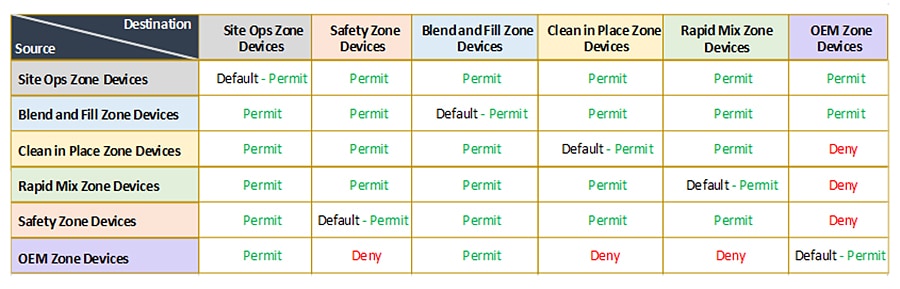
FactoryTalk System Overview
A FactoryTalk system is composed of software products, services, and hardware devices participating together and sharing the same FactoryTalk Directory and FactoryTalk services. In every FactoryTalk System, one computer must be designated as the FactoryTalk Directory server (FTD). The FTD is the centerpiece of the FactoryTalk Services Platform, providing a central lookup service for all products participating in an application. The role of the FTD in the Rockwell Automation environment is analogous to the role of a Domain Controller in the Microsoft Windows environment.
There are currently two types of FactoryTalk Directories:
- A Local FactoryTalk Directory (Local FTD) is typically used in a single (standalone) computer system. The Local FTD may or may not be connected to a Local Area Network (LAN).
- A Network FactoryTalk Directory (Network FTD) is designed primarily for use with a multiple (distributed) computer system, and it is normally connected to a LAN. Any other computers in the FactoryTalk system such as FactoryTalk View Site Edition (SE) and FactoryTalk Transaction Manager are clients to the designated Network FTD.
Note![]() FactoryTalk Live Data clients such as FactoryTalk View, FactoryTalk Transaction Manager, FactoryTalk Alarm and Events, FactoryTalk Linx Gateway, etc. rely on FactoryTalk Live Data service to manage connections between FactoryTalk products and data servers that are part of a FactoryTalk application. FactoryTalk Live Data handles and facilitates reading and writing values from and to OPC-DA servers as well as Live Data servers on behalf of these client software products. This type of communication uses various static and dynamic ports beyond the EtherNet/IP TCP 44818 and UDP 2222. It is recommended to implement the Microsoft Windows IPsec functionality to provide security services for IP network traffic between these client software products. In addition to IPsec, network traffic generated by the FactoryTalk View products and their components can be protected by SSL/TLS. For example, both FactoryTalk View SE and FactoryTalk ViewPoint support communication over HTTPS. For more details, see the Rockwell Automation Knowledgebase article QA46277 - “Deploying FactoryTalk Software with IPsec” (https://rockwellautomation.custhelp.com/app/answers/answer_view/a_id/1090456).
FactoryTalk Live Data clients such as FactoryTalk View, FactoryTalk Transaction Manager, FactoryTalk Alarm and Events, FactoryTalk Linx Gateway, etc. rely on FactoryTalk Live Data service to manage connections between FactoryTalk products and data servers that are part of a FactoryTalk application. FactoryTalk Live Data handles and facilitates reading and writing values from and to OPC-DA servers as well as Live Data servers on behalf of these client software products. This type of communication uses various static and dynamic ports beyond the EtherNet/IP TCP 44818 and UDP 2222. It is recommended to implement the Microsoft Windows IPsec functionality to provide security services for IP network traffic between these client software products. In addition to IPsec, network traffic generated by the FactoryTalk View products and their components can be protected by SSL/TLS. For example, both FactoryTalk View SE and FactoryTalk ViewPoint support communication over HTTPS. For more details, see the Rockwell Automation Knowledgebase article QA46277 - “Deploying FactoryTalk Software with IPsec” (https://rockwellautomation.custhelp.com/app/answers/answer_view/a_id/1090456).
A typical CIP Security implementation will be with a single Network FTD system. A Network FTD provides services to a group of hosts, with most FactoryTalk software utilizing the network directory as the Local FTD has little architecture options since it serves only the host upon which it is installed.
As a recommended best practice, the FactoryTalk Directory should be installed on an independent computer to allow the following:
- System Start-up—Most of the FactoryTalk software products rely on the various services provided by the FTD, the lowest risk scenario is to have it available as these products are initializing.
- Patching/Upgrading—Patching an FTD hosted on a dedicated computer translates to minimum system downtime, as it is not affecting the operation of other FactoryTalk components while rebooting.
- Securing and limiting physical access to computer hardware—Put measures in place to limit operator access and to protect your hardware systems. It is essential to limit operator access to the hardware running Windows operating systems and FTD. An operator with access to the power switch and bootable media could have direct access to the underlying file system and could potentially circumvent many of the security measures described in this document.
FactoryTalk Services Platform includes built-in security user groups (Figure 2-25) used to define user privileges for FactoryTalk Policy Manager. FactoryTalk user or Windows-linked user accounts created in FactoryTalk Administration Console can be added to the built-in security groups to grant specific rights in FactoryTalk Policy Manager. Table 2-9 lists the access rights for the built-in security user groups in FactoryTalk Policy Manager.
Figure 2-25 FactoryTalk Services Platform built-in Security User Groups
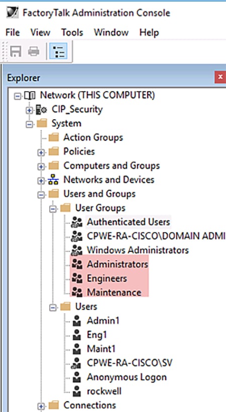
CIP Security Solution Use Cases
The solution use cases in Table 2-10 are addressed by CPwE CIP Security.

Warning![]() It is recommended to schedule downtime or maintenance window when deploying a CIP Security model to an IACS network. Before a deployed security policy becomes active, communications must be reset to all configured IACS devices, resulting in a short loss of connectivity. This will also allow time for any troubleshooting if needed.
It is recommended to schedule downtime or maintenance window when deploying a CIP Security model to an IACS network. Before a deployed security policy becomes active, communications must be reset to all configured IACS devices, resulting in a short loss of connectivity. This will also allow time for any troubleshooting if needed.
The workflow for onboarding, deleting, and replacing CIP Security capable IACS devices can be found in Chapter3, “CPwE CIP Security Configuration”
Use Case 1—CIP Security Protection with Zone to Zone Conduit
The recommended initial deployment of the CIP Security is to secure communication from the Level 3-Site Operations FactoryTalk Applications Zone(s) to each Levels 0-2 Cell/Area Zone(s) with CIP Security IACS devices. Typically, the Site Operations Zone contains the site-wide servers to each IACS Cell/Area Zone containing the controls and area supervisory assets. This is ideal since most threats originate from high in the architecture where Windows and other operating systems are more prevalent. These threats attempt to deny access or service, obtain sensitive data, or even input false commands to the lower level Industrial Zone. With the device identification and authentication properties of CIP Security, communicating entities must provide some information about themselves that is trustworthy and verifiable before data is accepted.
In this use case, CIP Security helps create protection for EtherNet/IP communications between the Level 3-Site Operations FactoryTalk Applications to each Cell/Area Zone(s) CIP Security IACS device (Levels 0-2) (Figure 2-26). Once CIP Security capable IACS devices are configured and deployed with security properties, RSLinx Classic will not be able to browse and discover those IACS devices unless a Trusted IP conduit is configured and deployed. FactoryTalk Linx version 6.11 or higher supports CIP Security and must be used to browse and discover IACS devices.
Retrofitting the 1756-EN4TR communication module in existing ControlLogix 5570 chassis to secure EtherNet/IP communications allows for a cost-effective and reliable approach to designing security into an existing network. The Safety Zone (red) and the Clean in Place Zone (yellow) used the CIP Security capable 1756-EN4TR communication module in the local ControlLogix 5570 chassis to secure EtherNet/IP communications with other zones.
Figure 2-26 Use Case 1—CIP Security Zone to Zone Conduit
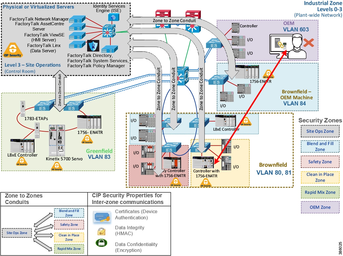
In Figure 2-27 the webpage of the local 1756-EN4TR with IP Address 10.17.81.51 shows the TCP connections after the CIP Security deployment. It has ten ESTABLISHED TCP connections, seven from trusted unsecured connections using port 44818 and three from trusted secure connections using port 2221. The local 1756-EN4TR is also both the client for some connections and a server for other connections.
Furthermore, it has accepted and ESTABLISHED an unsecured TCP connection from an untrusted IACS device Remote Address: 10.18.2.71 on Remote Port: 60422. In this scenario, the local 1756-EN4TR excludes the IACS device IP Address: 10.18.2.71 in its CIP Security configuration, therefore it is able to deny CIP connections, which can be seen in the Wireshark screen capture in Figure 2-28. This deny action will result in the IACS device’s (Remote Address: 10.18.2.71) ability to browse the backplane of the local 1756-EN4TR module therefore thwarting unwanted attempts of going online, uploading, or downloading to the local controller. Additionally, Studio 5000 Logix Designer will deny untrusted attempts with a popup Error: 0x032F: Ingress rule deny non-secure.
Figure 2-27 1756-EN4TR Webpage (TCP Connections Page)
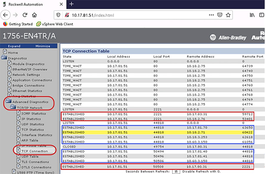
Figure 2-28 1756-EN4TR Denies Untrusted IACS Device
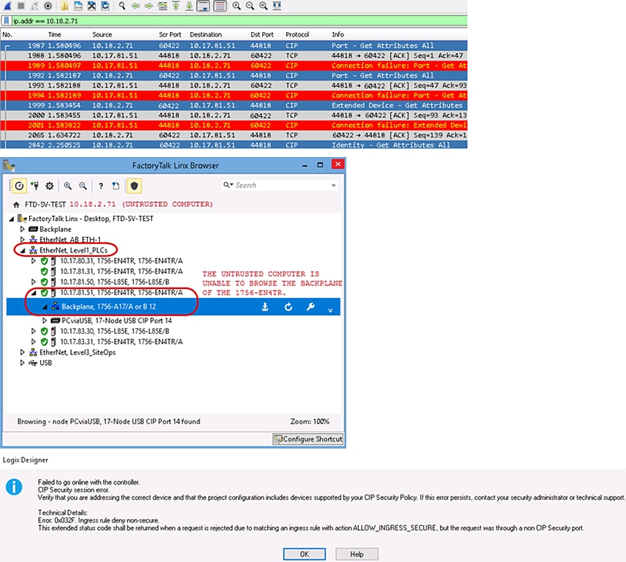
Use Case 2—CIP Security Protection with Device to Device or Zone Conduits
Data in transit can be intercepted, allowing for sensitive information such as secret recipes to be stolen. Even worse, data tampering by way of unauthorized changes to configuration, programs, commands, or alarming may cause personnel to initiate incorrect actions leading to a number of undesirable events, such as equipment damage, operation unavailability, endangering human life, and environmental impacts.
CIP Security helps create protection for east-west traffic flow for EtherNet/IP communications between IACS devices in different zones (Figure 2-29), for example ControlLogix to ControlLogix message instructions (MSG) will use data integrity to confirm data was not altered in transit and optionally enable data confidentiality to help protect intellectual property with the help of the TLS network protocol. Rockwell Automation, Cisco, and Panduit recommend using device and data authentication/integrity without encryption for CIP Motion or I/O applications.
Note![]() CIP Motion application was not tested or validated as part of CPwE CIP Security. See the specific vendor IACS device technical specification publication for performance and capacity.
CIP Motion application was not tested or validated as part of CPwE CIP Security. See the specific vendor IACS device technical specification publication for performance and capacity.
OEMs can seamlessly integrate CIP Security IACS devices into a customer’s plant-wide architecture. The OEM would test and qualify the skid/machine with the required CIP Security properties enabled. Before shipping the skid/machine, CIP Security must be completely cleared using the FactoryTalk Policy Manager commissioning tool software. The OEM could provide documentation and guidance in terms of what options to select for reasonable performance. It would be up to the end user to apply security. See Removing the CIP Security Policy from an IACS Device in Chapter3, “CPwE CIP Security Configuration”
Figure 2-29 Use Case 2—CIP Security Device to Device or Zone Conduit
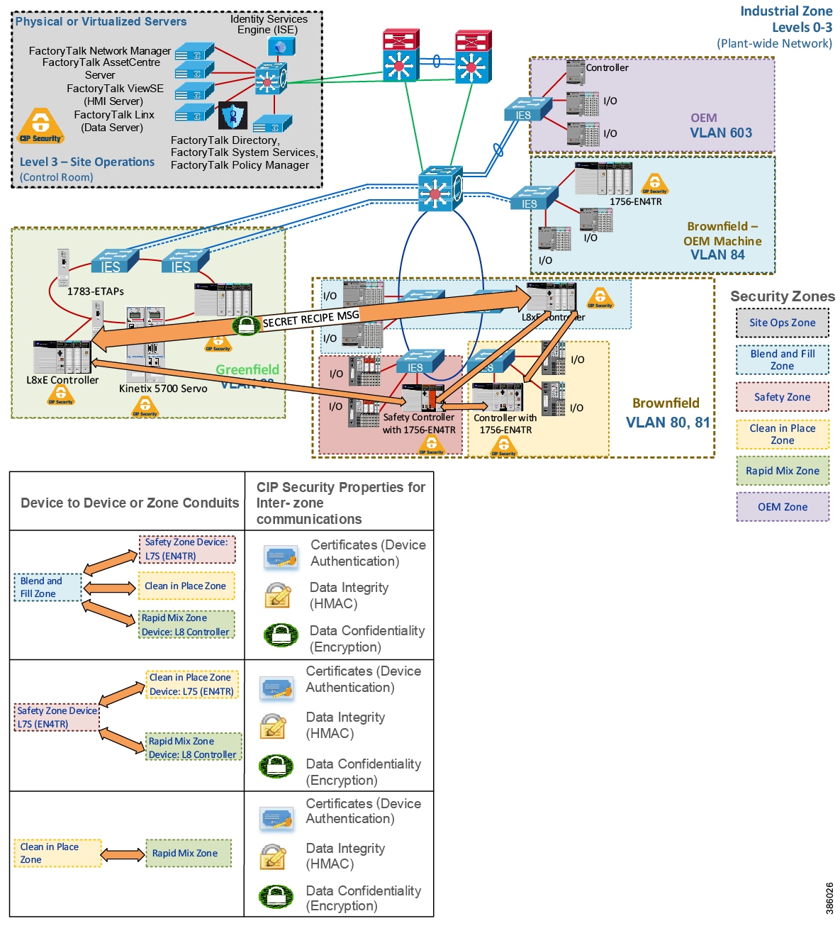
In Figure 2-30 the two 1756-L85Es named Blue and Green are communicating using an MSG. Green is reading a tag named Read_L8_String from Blue. In the following Wireshark screen capture, the value being passed in the tag is the string 'SECRETRECIPE11'. Even with the CIP Security data integrity in place to verify the data was not altered in transit, without data confidentiality (encryption), intellectual property and even passwords are sent in plaintext making it available for anyone running Wireshark on the network to capture and steal sensitive information.
Figure 2-30 Unencrypted MSG between Two 1756-L85Ess
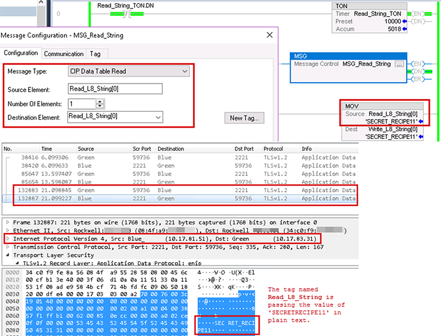
In Figure 2-31 the same two 1756-L85Es are now communicating using CIP Security data integrity and data confidentiality (encryption) enabled. Green can read the tag value as 'SECRETRECIPE111' because it has the correct shared secret key to decrypt. The Wireshark screen capture now shows the payload of the two 1756-L85Es as encrypted and unreadable without the correct shared secret key to decrypt.
Figure 2-31 Encrypted MSG between Two 1756-L85Es
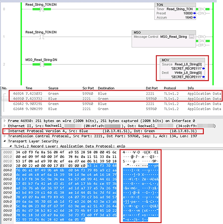
Use Case 3—CIP Security Protection with Trusted IP Conduits
Rockwell Automation IACS devices and software currently supporting CIP Security are still able to interoperate with IACS devices that do not support CIP Security on the network by using the Trusted IP feature. The feature can be implemented to authorize CIP communication between an IACS device that is capable of CIP Security and one that is not based on IP address. The security properties of the Trusted IP conduit cannot be extended to secure communications for other industrial protocols like Modbus or common Internet protocols like ICMP.
For IACS applications, use FactoryTalk Policy Manager to create Trusted IP conduits for trusted IP addresses in EtherNet/IP communications between non-CIP Security IACS devices and applications to CIP Security IACS devices. Essentially, the tool deploys two kinds of Trusted IP conduits, an explicitly defined Trusted IP conduit and an implied Trusted IP through a secure CIP Security enabled conduit.
Explicitly Defined Trusted IP Conduit
When a zone contains all non-CIP Security capable IACS devices like the OEM Zone (purple) and an IACS belonging to that zone, it must initiate a CIP connection to an IACS device with CIP Security capability in another zone. Then an explicitly defined Trusted IP conduit must be configured in the Conduits component page of FactoryTalk Policy Manager. In Figure 2-32 a Trusted IP conduit must be defined and explicitly created for the OEM Zone (purple) CompactLogix 5380 (5069-L340ERM) to send an MSG to the Blend and Fill Zone (blue) ControlLogix 5580 (1756-L85E).
When a zone like the Site Ops Zone (gray) contains an inter-mix of CIP Security capable IACS devices and ones that are not, the non-CIP Security capable IACS devices will have a yellow triangle information icon displayed next to them in the tool. When a zone to zone or device conduit is created with CIP Security enabled, for example the Site Ops Zone (gray), the CIP Security capable IACS devices will implicitly trust the non-CIP Security capable IACS devices using the Trusted IP capability. The non-CIP Security capable IACS devices will not be able to use any of the CIP Security properties configured on the zone or the conduits for communication. Additionally, it is no need to create a second conduit for the Site Ops Zone (gray) specifically for the Trusted IP capability to the non-CIP Security capable IACS devices. As an example, in Figure 2-33 FactoryTalk Network Manager is an application that does not support CIP Security. However, it can initiate CIP connections to other zones through a CIP Security enabled zone to zone conduit and therefore their IP addresses are implicitly trusted by CIP Security enabled IACS devices in other zones.
Figure 2-32 Use Case 3—Rockwell Automation CIP Security Trusted IP Conduits
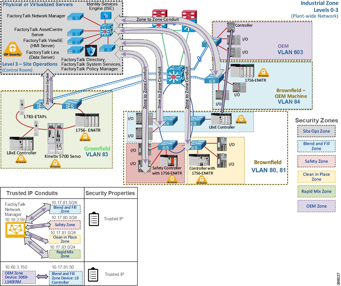
Figure 2-33 CIP Connections to Other Zones through a CIP Security Enabled Zone to Zone Conduit
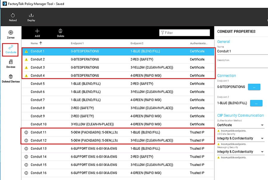
 Feedback