Verifying and Troubleshooting the Deployment
This chapter provides an overview of some of the verification and troubleshooting tools that can be used to complete the verification and any troubleshooting of the CIP Security deployment. It also provides a basic overview of Wireshark and webpages for the 1756-L8xE and 1756-EN4TR to help with basic verification and troubleshooting. However, it does not specifically prescribe action items as a result of the troubleshooting steps due to the fluidity of the deployment and potential architectural differences.
Web Browser Verification
Identify the TCP Connections
Many IACS devices have a webpage that display information about the module including the CIP connections established. This is a quick way to determine TCP connections between IACS before FactoryTalk Policy Manager deploys the security model. The webpages of the 1756-L8xE and 1756-EN4TR can help identify the initiator and responder of a CIP connection. This will help define conduits for protected EtherNet/IP communication in different zones. Any EtherNet/IP communication between zones must be through a defined conduit.

Note The client/server terminology is commonly used with TCP and TLS/DTLS connections and originator/target for CIP connection. However, for simplicity of this document, the terms client/server will be generalized when discussing the behavior associated with a connection of an IACS device. The client initiates a connection and the server listens for and accepts a connection. For more details, see EtherNet/IP Overview in Chapter2, “CPwE CIP Security Design Considerations”
The 1756-L8xE and 1756-EN4TR have a similar folder structure in the webpage navigation. The TCP Connections page, TLS Connections page, and the DTLS Connections page are provided in both the 1756-L8xE and 1756-EN4TR.
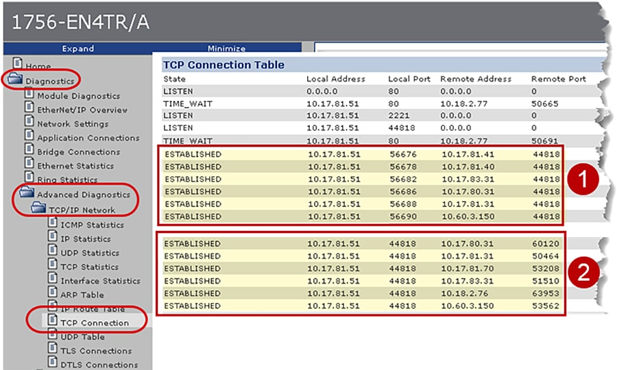
Figure 4-1 shows the webpage of the local 1756-EN4TR with IP Address 10.17.81.51 TCP connections before CIP Security deployment. It has two sets of ESTABLISHED TCP connections because the local 1756-EN4TR is the client for some connections and a server for other connections.
1.![]() The first set of connections shows the local 1756-EN4TR with IP Address 10.17.81.51. It has initiated and ESTABLISHED TCP connections to several IACS devices (Remote Address) on the Remote (destination) port 44818.
The first set of connections shows the local 1756-EN4TR with IP Address 10.17.81.51. It has initiated and ESTABLISHED TCP connections to several IACS devices (Remote Address) on the Remote (destination) port 44818.
2.![]() The second set of connections show the local 1756-EN4TR with IP Address 10.17.81.51. It has accepted and ESTABLISHED TCP connections on its local port of 44818 from several IACS devices (Remote Address) on random Remote (destination) port numbers.
The second set of connections show the local 1756-EN4TR with IP Address 10.17.81.51. It has accepted and ESTABLISHED TCP connections on its local port of 44818 from several IACS devices (Remote Address) on random Remote (destination) port numbers.
Figure 4-1 1756-EN4TR Webpage (TCP Connections page) before CIP Security
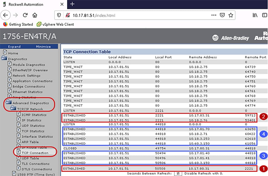
In Figure 4-2 the webpage of the local 1756-EN4TR with IP Address 10.17.81.51 shows the TCP connections after the CIP Security deployment. It has four sets of ESTABLISHED TCP connections because the local 1756-EN4TR module is the client for some connections and a server for other connections.
1.![]() The first set of connections shows the local 1756-EN4TR with IP Address 10.17.81.51. It has initiated and ESTABLISHED secured TCP connections to one IACS devices (Remote Address) on the Remote (destination) port 2221.
The first set of connections shows the local 1756-EN4TR with IP Address 10.17.81.51. It has initiated and ESTABLISHED secured TCP connections to one IACS devices (Remote Address) on the Remote (destination) port 2221.
2.![]() The local 1756-EN4TR with IP Address 10.17.81.51. It has accepted and ESTABLISHED TCP secured connections on its local port of 2221 from several IACS devices (Remote Address) on random Remote (destination) port numbers.
The local 1756-EN4TR with IP Address 10.17.81.51. It has accepted and ESTABLISHED TCP secured connections on its local port of 2221 from several IACS devices (Remote Address) on random Remote (destination) port numbers.
3.![]() The local 1756-EN4TR with IP Address 10.17.81.51. It has initiated and ESTABLISHED unsecured TCP connections to several IACS devices (Remote Address) on the Remote (destination) port 44818.
The local 1756-EN4TR with IP Address 10.17.81.51. It has initiated and ESTABLISHED unsecured TCP connections to several IACS devices (Remote Address) on the Remote (destination) port 44818.
4.![]() The local 1756-EN4TR with IP Address 10.17.81.51. It has accepted and ESTABLISHED TCP unsecured connections on its local port of 44818 from several IACS devices (Remote Address) on random Remote (destination) port numbers.
The local 1756-EN4TR with IP Address 10.17.81.51. It has accepted and ESTABLISHED TCP unsecured connections on its local port of 44818 from several IACS devices (Remote Address) on random Remote (destination) port numbers.
Note![]() The Remote Address IACS devices using the TCP connection to port 44818 after CIP Security has been deployed are the IACS devices that do not support the CIP Security feature. The local 1756-EN4TR currently supports CIP Security and can interoperate with IACS devices that do not support CIP Security on the network on the standard TCP/UDP ports of 44818 and 2222. For more details, see Trusted IP Communication in Chapter2, “CPwE CIP Security Design Considerations”
The Remote Address IACS devices using the TCP connection to port 44818 after CIP Security has been deployed are the IACS devices that do not support the CIP Security feature. The local 1756-EN4TR currently supports CIP Security and can interoperate with IACS devices that do not support CIP Security on the network on the standard TCP/UDP ports of 44818 and 2222. For more details, see Trusted IP Communication in Chapter2, “CPwE CIP Security Design Considerations”
Figure 4-2 1756-EN4TR Webpage (TCP Connections page) after CIP Security
Identify the TLS Connections
Once the security model has been successfully deployed, the webpages of the 1756-L8xE and 1756-EN4TR can help identify the cipher suite configured between the client and the server IACS device. TLS connections are the class 3 explicit messaging such as MSG instruction and CIP administration.
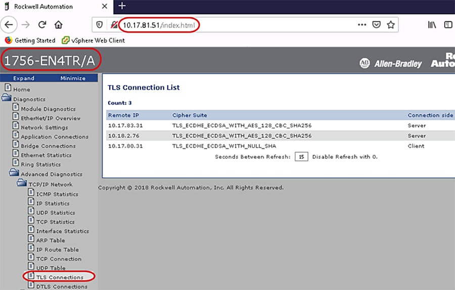
In Figure 4-3 the webpage of the local 1756-EN4TR with IP Address 10.17.81.51 has three ESTABLISHED TLS connections:
1.![]() Remote IP: 10.17.83.31 (Green_EN4TR)
Remote IP: 10.17.83.31 (Green_EN4TR)
Each cipher suite has a unique name that is used to identify it and to describe the algorithmic contents of it. Each segment in a cipher suite name represents another algorithm or protocol. The meaning of this name is:
–![]() TLS defines the protocol used in the cipher suite
TLS defines the protocol used in the cipher suite
–![]() Elliptic Curve Diffie-Hellman Ephemeral (ECDHE) is used for the key exchange
Elliptic Curve Diffie-Hellman Ephemeral (ECDHE) is used for the key exchange
–![]() Elliptic Curve Digital Signature Algorithm (ECDSA) is used for the authentication
Elliptic Curve Digital Signature Algorithm (ECDSA) is used for the authentication
–![]() Advanced Encryption Standard with 128-bit key in Cipher Block Chaining mode (AES 128 CBC) is used for the encryption
Advanced Encryption Standard with 128-bit key in Cipher Block Chaining mode (AES 128 CBC) is used for the encryption
–![]() Secure Hash Algorithm 256 (SHA256) is used for the hash
Secure Hash Algorithm 256 (SHA256) is used for the hash
This means the local 1756-EN4TR with IP Address 10.17.81.51 has accepted the TLS connection from the IACS Remote IP: 10.17.83.31 (Green_EN4TR).
2.![]() Remote IP: 10.18.2.76 (FactoryTalk Linx Data Server)
Remote IP: 10.18.2.76 (FactoryTalk Linx Data Server)
3.![]() Remote IP: 10.17.80.31 (Red_EN4TR)
Remote IP: 10.17.80.31 (Red_EN4TR)
The meaning of the cipher suite applied is:
–![]() TLS defines the protocol used in the cipher suite
TLS defines the protocol used in the cipher suite
–![]() ECDHE used for the key exchange
ECDHE used for the key exchange
–![]() ECDSA used for the authentication
ECDSA used for the authentication
–![]() NULL means no encryption is used
NULL means no encryption is used
This means the local 1756-EN4TR with IP Address 10.17.81.51 has initiated the TLS connection to the IACS Remote IP: 10.17.80.31 (Red_EN4TR).
Figure 4-3 1756-EN4TR Webpage (TLS Connections Page)
Identify the DTLS Connections
Once the security model has been successfully deployed, the webpages of the 1756-L8xE and 1756-EN4TR can help identify the cipher suite configured between the IACS devices. DTLS connections are the class 0/1 implicit messaging such as I/O connections and produced/consume connections.
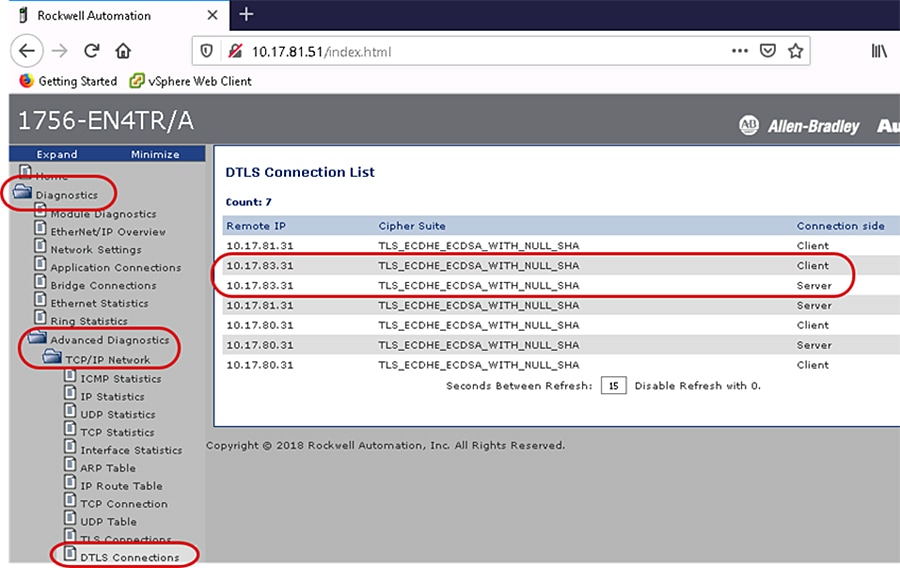
In Figure 4-4 the webpage of the local 1756-EN4TR with IP Address 10.17.81.51 has seven ESTABLISHED DTLS connections. The following description explains the two connections to the same Remote IP IACS device Remote IP: 10.17.83.31.
1.![]() Remote IP: 10.17.83.31 (Green_EN4TR)
Remote IP: 10.17.83.31 (Green_EN4TR)
The meaning of applied cipher suite is:
–![]() TLS defines the protocol used in the cipher suite
TLS defines the protocol used in the cipher suite
–![]() ECDHE used for the key exchange
ECDHE used for the key exchange
–![]() ECDSA used for the authentication
ECDSA used for the authentication
–![]() NULL means no encryption is used
NULL means no encryption is used
This means the local 1756-EN4TR with IP Address 10.17.81.51 is the server and the client for the DTLS connection from the client and server IACS Remote IP: 10.17.83.31 (Green_EN4TR). The IACS application being used is produced/consume between the two 1756-EN4TRs. The local 1756-EN4TR is producing data for the Green_EN4TR to consume and inversely the Green_EN4TR is also a producer of another set of data for the local 1756-EN4TR to consume.
Figure 4-4 1756-EN4TR Webpage (DTLS Connections Page)
Identify the Confidentiality Connections
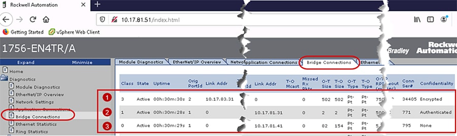
The webpages of the 1756-L8xE and 1756-EN4TR can help identify the active bridge connections between the IACS devices and what CIP Security properties are being used for the connection. The Bridge Connections page displays the type of CIP messaging either class 3 explicit message or class 0/1 implicit message along with the CIP Security property applied in the Confidentiality column.
Figure 4-5 shows the webpage of the local 1756-EN4TR with IP Address 10.17.81.51 active bridge connections after the CIP Security deployment. It has three sets of active connections:
1.![]() The first row shows a class 3 active connection from an IACS device identified as Link Addr: 10.17.83.31 (Green_EN4TR). Encrypted is displayed in the Confidentiality column, concluding this connection is using all three CIP Security properties: device authentication, data integrity and confidentiality.
The first row shows a class 3 active connection from an IACS device identified as Link Addr: 10.17.83.31 (Green_EN4TR). Encrypted is displayed in the Confidentiality column, concluding this connection is using all three CIP Security properties: device authentication, data integrity and confidentiality.
2.![]() The second row shows a class 1 active connection to an IACS device identified as Link Addr: 10.17.81.31 (Yellow_EN4TR). Authenticated is displayed in the Confidentiality column, concluding this connection is using only two of the CIP Security properties: device authentication, and data integrity.
The second row shows a class 1 active connection to an IACS device identified as Link Addr: 10.17.81.31 (Yellow_EN4TR). Authenticated is displayed in the Confidentiality column, concluding this connection is using only two of the CIP Security properties: device authentication, and data integrity.
3.![]() The third row shows a class 0 active connection to a server identified as Link Addr: 10.17.81.41 (5069-I/O device). None is displayed in the Confidentiality column, concluding this connection is not using any of the CIP Security properties.
The third row shows a class 0 active connection to a server identified as Link Addr: 10.17.81.41 (5069-I/O device). None is displayed in the Confidentiality column, concluding this connection is not using any of the CIP Security properties.
Figure 4-5 1756-EN4TR Webpage (Bridge Connections Page) after CIP Security
Wireshark Verification
Identify the Initial Deployment of CIP Security
Wireshark is a widely used network protocol analyzer. It is a free and open-source packet analyzer commonly used for network troubleshooting, protocol analysis, software and communications protocol development, and education. The purpose of traffic analysis is to determine who is talking to whom.
In the initial release of the CIP Security feature in Rockwell Automation products, the ODVA PUSH method is used for CIP Security provisioning. In this method, the initial deployment of the CIP Security model sets the configuration tool (FTPM/FTSS) as the client initiating the connection and the IACS device as the server in a TLS handshake. Figure 4-6 captures the initial deployment of CIP Security from the computer hosting FactoryTalk Policy Manger (FTPM) and FactoryTalk System Service (FTSS) to a 1756-L85E (Blue_L85E).
1.![]() A reliable TCP connection is needed for communication between the two IACS devices. The TCP connection is established on the secure port 2221. The client is the FTPM/FTSS computer and the server the Blue_L85E.
A reliable TCP connection is needed for communication between the two IACS devices. The TCP connection is established on the secure port 2221. The client is the FTPM/FTSS computer and the server the Blue_L85E.
2.![]() A secure TLS connection is created for the TLS handshake protocol. The client is the FTPM/FTSS computer and the server the Blue_L85E.
A secure TLS connection is created for the TLS handshake protocol. The client is the FTPM/FTSS computer and the server the Blue_L85E.
The client sends a message to the server, asking for an encrypted session, which includes:
–![]() The highest TLS version supported by the client.
The highest TLS version supported by the client.
–![]() Ciphers supported by the client. The ciphers are listed in order of preference.
Ciphers supported by the client. The ciphers are listed in order of preference.
–![]() Data compression methods that are supported by the client.
Data compression methods that are supported by the client.
–![]() The session ID. If the client is starting a new TLS session, the session ID is 0.
The session ID. If the client is starting a new TLS session, the session ID is 0.
–![]() Random data that is generated by the client for use in the key generation process.
Random data that is generated by the client for use in the key generation process.
The server sends a SERVER_HELLO command to the client, which includes:
–![]() The TLS version that will be used for the TLS session.
The TLS version that will be used for the TLS session.
–![]() The cipher that will be used for the TLS session.
The cipher that will be used for the TLS session.
–![]() Data compression method that will be used for the TLS session.
Data compression method that will be used for the TLS session.
–![]() The session ID for the TLS session.
The session ID for the TLS session.
–![]() Random data that is generated by the server for use in the key generation process.
Random data that is generated by the server for use in the key generation process.
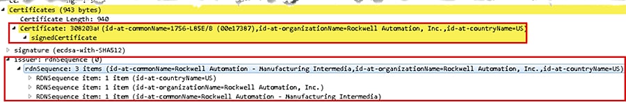
The server responds with their server certificate, which includes the server public key in it. The server is the 1756-L85E and the certificate it sends is the born on certificate or vendor certificate as a root certificate-see—see Figure 4-7.
This message is optional and sent when the public key that is present in the server’s certificate is not suitable for key exchange or if the cipher suite places a restriction requiring a temporary key. This key is used by the client to encrypt Client Key Exchange later in the process. The 1756-L85E does not use its born on certificate or vendor certificate as a basis for trust when it is being configured with new trust anchors and certificates. Once security has been set up by FactoryTalk Policy Manager, trust is limited to the trust anchors that the tool has provisioned, and the vendor certificate becomes irrelevant.
The server sends the SERVER_DONE command. This command indicates that the server has completed this phase of the TLS handshake and is awaiting the client's response.
Using all data generated in the handshake thus far, both will perform the following:
–![]() The client generates the pre-master secret "random value" for the session, encrypts it with the server's public key (obtained from the server's certificate) and sends the encrypted pre-master secret to the server. The pre-master secret is a random value generated by the client and encrypted with the server public key. The pre-master key's length can vary depending on the algorithm used during key exchange. This along with the client and server random number is used to create the master secret. If the server can decrypt the message using the server's private key and can create the master secret locally, then the client is assured that the server has authenticated itself.
The client generates the pre-master secret "random value" for the session, encrypts it with the server's public key (obtained from the server's certificate) and sends the encrypted pre-master secret to the server. The pre-master secret is a random value generated by the client and encrypted with the server public key. The pre-master key's length can vary depending on the algorithm used during key exchange. This along with the client and server random number is used to create the master secret. If the server can decrypt the message using the server's private key and can create the master secret locally, then the client is assured that the server has authenticated itself.
–![]() The server uses its private key to decrypt the pre-master secret.
The server uses its private key to decrypt the pre-master secret.
–![]() Both the client and the server use the pre-master key and performs a series of steps to compute and generate the same master secret locally. The master secret is then used to derive a shared secret key/session key for symmetric encryption and MAC. The master secret is of fixed-length value.
Both the client and the server use the pre-master key and performs a series of steps to compute and generate the same master secret locally. The master secret is then used to derive a shared secret key/session key for symmetric encryption and MAC. The master secret is of fixed-length value.
–![]() Both the client and the server use the master secret to generate the session keys, which are symmetric keys used to encrypt and decrypt information exchanged during the SSL session and to verify its integrity.
Both the client and the server use the master secret to generate the session keys, which are symmetric keys used to encrypt and decrypt information exchanged during the SSL session and to verify its integrity.
The client sends a message to the server informing it that future messages from the client will be encrypted with the session key and indicates that its portion of the handshake is finished.
The server sends a verification message to the client, which has the HMAC for data integrity and encrypted by shared secret key. It also indicates that its portion of the handshake is finished.
The TLS handshake is now complete and the session begins. The client and the server use the shared secret key to encrypt and decrypt the data they send to each other and to validate its integrity.
3.![]() At this point, both client (FTPM/FTSS computer) and server (Blue_L85E) have successfully completed the TLS handshake. Application data is then exchanged using the symmetric encryption and HMAC. In symmetric encryption, the exact same key is used on both sides of a conversation, for both encrypting and decrypting. The application data packets exchanged set the initial configurations deployed in the FactoryTalk Policy Manager security model to the CIP Security capable IACS devices. During this time, application data packets are exchanged to set the appropriate CIP Security objects including the CIP Security object, the certificate management object (CMO) and EtherNet/IP Security object. It also includes the provisioning of the client certificate or new trust anchors for the CIP Security devices in that security model. The client (FTPM/FTSS computer) instructs the server (Blue_L85E) to create a certificate signing request (CSR), which includes the server creating a public/private key pair. The private key stays on the server and is never shared with the client or any other IACS devices. The client reads the CSR, digitally signs it then sends it back as a client certificate, which will be used as device authentication.
At this point, both client (FTPM/FTSS computer) and server (Blue_L85E) have successfully completed the TLS handshake. Application data is then exchanged using the symmetric encryption and HMAC. In symmetric encryption, the exact same key is used on both sides of a conversation, for both encrypting and decrypting. The application data packets exchanged set the initial configurations deployed in the FactoryTalk Policy Manager security model to the CIP Security capable IACS devices. During this time, application data packets are exchanged to set the appropriate CIP Security objects including the CIP Security object, the certificate management object (CMO) and EtherNet/IP Security object. It also includes the provisioning of the client certificate or new trust anchors for the CIP Security devices in that security model. The client (FTPM/FTSS computer) instructs the server (Blue_L85E) to create a certificate signing request (CSR), which includes the server creating a public/private key pair. The private key stays on the server and is never shared with the client or any other IACS devices. The client reads the CSR, digitally signs it then sends it back as a client certificate, which will be used as device authentication.
Figure 4-6 Initial Deployment of CIP Security
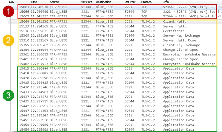
Figure 4-7 CIP Security Vendor Certificate
Identify Class 3 Explicit Communication with CIP Security
After the initial security model has been deployed, each CIP Security capable IACS device will have their respective client certificates signed by a mutual CA, which is the FTPM/FTSS computer. The client certificate will serve as the IACS device’s proof of authentication. Certificates are agreements between communicating parties and a common entity called a Certificate Authority (CA). The CA is a trusted entity that manages and issues security certificates to requesters to prove their identities and public keys that are used for secure communication in an IACS network. Mutual trust is established when communicating parties exchange certificates signed by a common CA.
Figure 4-8 captures two 1756-L85Es exchanging client certificates then establishing a CIP connection for a class 3 explicit message. The 1756-L85E (Blue_L85E) is the client and the 1756-L85E (Green_L85) is the server. It follows the same client and server data flow as the initial deployment except after both IACS devices are finished with the TLS handshake, they will perform the CIP Connection Manager Forward_Open request all on the secure CIP TCP Port 2221.
Figure 4-8 Class 3 Explicit Messaging CIP Security
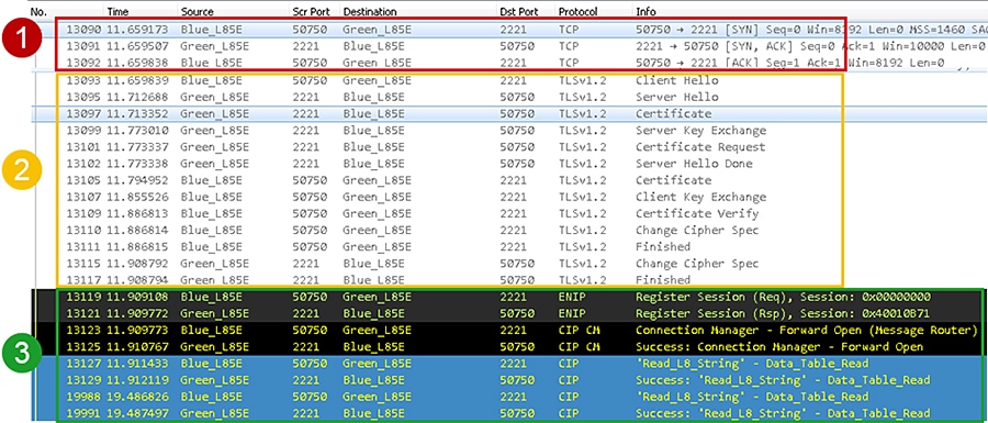
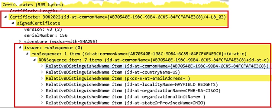
Figure 4-9 displays the client certificate the 1756-L85E (Green_L85) is presenting to the 1756-L85E (Blue_L85E). The client certificate contents are much different from the vendor certificate. The issuer contents displays the information set in the FactoryTalk Policy Manager Global settings.
Figure 4-9 CIP Security Client Certificate
Identify Class 0/1 Implicit Communication with CIP Security
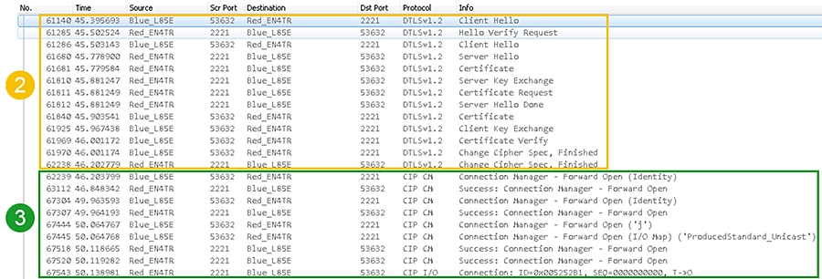
Figure 4-10 captures a 1756-L85E and 1756-EN4TR exchanging client certificates then establishing a CIP connection for a class 0/1 implicit message. The 1756-L85E (Blue_L85E) is the client and the 1756-EN4TR (Red_EN4TR) is the server. It follows the same client and server data flow as the initial deployment except after both IACS devices are finished with the DTLS handshake, they will perform the CIP Connection Manager Forward_Open request all on the secure CIP TCP Port 2221.
Figure 4-10 Class 0/1 Implicit Messaging CIP Security
Deployment Troubleshooting
In FactoryTalk Policy Manager, after deployment, review the Results tab for the result of the deployment on each item in the model. The possible results are:
- Configuration complete. No issues identified.
- Configuration complete. Warnings identified.
- Configuration not complete. Error identified.
The Online Help in the FactoryTalk Policy Manager top main menu bar includes a reference of the possible errors and warning along with descriptions encountered during deployment.
Reloading the model synchronizes FactoryTalk Policy Manager and FactoryTalk System Services and refreshes the display of possible conflicts so that they can be addressed before deployment. The Reload button is in the FactoryTalk Policy Manager top main menu bar.
Verify the computer hosting FactoryTalk Policy Manager has successfully communications to all required IACS devices. This includes but not limited to: ping, tracert, can be browsed in FactoryTalk Linx Browser utility or FactoryTalk Linx in the Administration Console.
CIP Security IACS devices must be discoverable by FactoryTalk Linx to apply and deploy CIP Security properties. FactoryTalk Linx Browser utility cannot be used to modify, enable or disable the CIP Security properties on IACS devices. Please use the FactoryTalk Policy Manager software to modify, enable or disable CIP Security properties.
Deleting the IACS device from the model does not remove the security configuration. Even if FactoryTalk Policy Manager and FactoryTalk System Services are uninstalled the security policy configured for the IACS device is still in effect on that IACS device. The recommended steps to remove any CIP Security configurations on an IACS device are detailed in Removing the CIP Security Policy from an IACS Device in Chapter3, “CPwE CIP Security Configuration”
 Feedback