CPwE CIP Security Configuration
This chapter describes how to configure CIP Security Zones and Conduits within the CPwE architecture based on the design considerations and recommendations of Chapter2, “CPwE CIP Security Design Considerations” The included configurations have been verified during reference architecture testing.
This chapter is not intended to provide step-by-step procedures to configure the network infrastructure devices such as routers, firewalls, or IES due to the variability in network architectures. Presumably, the network IACS devices will have end-to-end connectivity to the computer or server hosting the Network FTD, which also has the FactoryTalk System Services, and FactoryTalk Policy Manager installed on it. However, this chapter discusses specific items related to FactoryTalk applications and IACS devices and their interaction with CIP Security. This section includes the steps required to properly configure and deploy CIP Security features in FactoryTalk Policy Manager to help achieve secure EtherNet/IP communications in an IACS.

Note![]() The client/server terminology is commonly used with TCP and TLS/DTLS connections and originator/target for CIP connection. However, for simplicity of this document, the terms client/server will be generalized and used throughout this document when discussing the behavior associated with a connection of an IACS device. The client initiates a connection and the server listens for and accepts a connection.
The client/server terminology is commonly used with TCP and TLS/DTLS connections and originator/target for CIP connection. However, for simplicity of this document, the terms client/server will be generalized and used throughout this document when discussing the behavior associated with a connection of an IACS device. The client initiates a connection and the server listens for and accepts a connection.
Overview
FactoryTalk Policy Manager is the commissioning tool GUI used to configure, deploy, and view the system communication for CIP Security properties. When a user logs in to the tool, the menu divides the system security policy into different components. Use these components to design security models that control the permissions and usage of IACS devices within the system.
- Zone component—Groups of IACS devices.
- Conduit component—Communication routes between components.
- Device component—Computers, controllers, modules, HMI panels, and drives.
- Deleted Devices component—Delete IACS device that is no longer needed. After an IACS device is deleted it will be listed in the Deleted Devices table until the next time the model is deployed.
A fully configured instance with zones, devices, and conduits along with their respective CIP Security properties inside FactoryTalk Policy Manager is referred to a security model.
FactoryTalk Policy Manager depends on FactoryTalk System Services for certificate services, policy deployment, and authentication. FactoryTalk System Services is the service that signs and issues client certificates to give assurance for a communicating party's authenticity. It runs as a service in the background to help enable the deployment of the CIP Security model configured in the FactoryTalk Policy Manager commissioning tool.
The CPwE CIP Security model consisted of multiple zones and conduits with a mix of intra-zone and inter-zone security properties applied based on functional and security requirements obtained from the security risk assessment process. Each organization's functional and security requirements will vary based on their own security risk assessments.
The CPwE CIP Security model security zones containing various VLANs (Figure 3-1).
- 0-Site Operations Zone
- 1-Blue (Blend/Fill) Zone
- 2-Red (Safety) Zone
- 3-Yellow (Clean in Place (CIP)) Zone
- 4-Green (Rapid Mix) Zone
- 5-OEM (Packaging) Zone
- 6-Support EWS Zone
Note![]() The numerical values [0-6] shown before the zone name are locally significant and only used in the security model configuration for better organization of the zones for publication purposes.
The numerical values [0-6] shown before the zone name are locally significant and only used in the security model configuration for better organization of the zones for publication purposes.
Table 3-1 contains the following IACS devices and Zone Properties for each zone in the CPwE CIP Security model.
–![]() Level 3 Site Operations contains the assets that are critical to monitoring and controlling the plant-wide or site-wide industrial operations. Data flow will typically be class 3 HMI communications to and from IACS devices.
Level 3 Site Operations contains the assets that are critical to monitoring and controlling the plant-wide or site-wide industrial operations. Data flow will typically be class 3 HMI communications to and from IACS devices.
–![]() Level 2 Supervisory control contains the local management software where Engineering workstations (EWS) use class 3 CIP administration communications for uploading/downloading projects to the controllers.
Level 2 Supervisory control contains the local management software where Engineering workstations (EWS) use class 3 CIP administration communications for uploading/downloading projects to the controllers.
- 1-Blue (Blend/Fill), 2-Red (Safety), 3-Yellow (Clean in Place (CIP)), 4-Green (Rapid Mix), and 5-OEM (Packaging) Zones combines functional zones Levels 0-1 IACS devices. These areas are critical to help ensure that industrial operations continue. Typically, class 0/1 and 3 types of traffic can occur at these levels.
–![]() Level 1 Control system contains the controllers instructing the Level 0 IACS devices and gathering data about a particular process.
Level 1 Control system contains the controllers instructing the Level 0 IACS devices and gathering data about a particular process.
–![]() Level 0 Process contains the sensors, actuators, drives, and robots performing the functions of the process.
Level 0 Process contains the sensors, actuators, drives, and robots performing the functions of the process.
Figure 3-1 Zones in the CPwE CIP Security Model
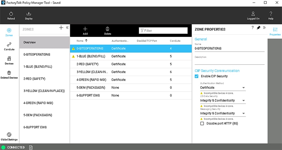
Table 3-1 contains the following IACS devices and Zone Properties for each zone in the CPwE CIP Security model. Intra-zone security properties are the policies configured on the individual zone and would apply to all IACS devices and CIP application data within that zone but not between other zones. Each zone is applied with the security properties based on functional and security requirements obtained from conducting a security risk assessment.
|
||
|
1.The following catalog numbers with the associated firmware versions currently support CIP Security. See System Components in Chapter 2, “CPwE CIP Security Design Considerations” for a complete list. |
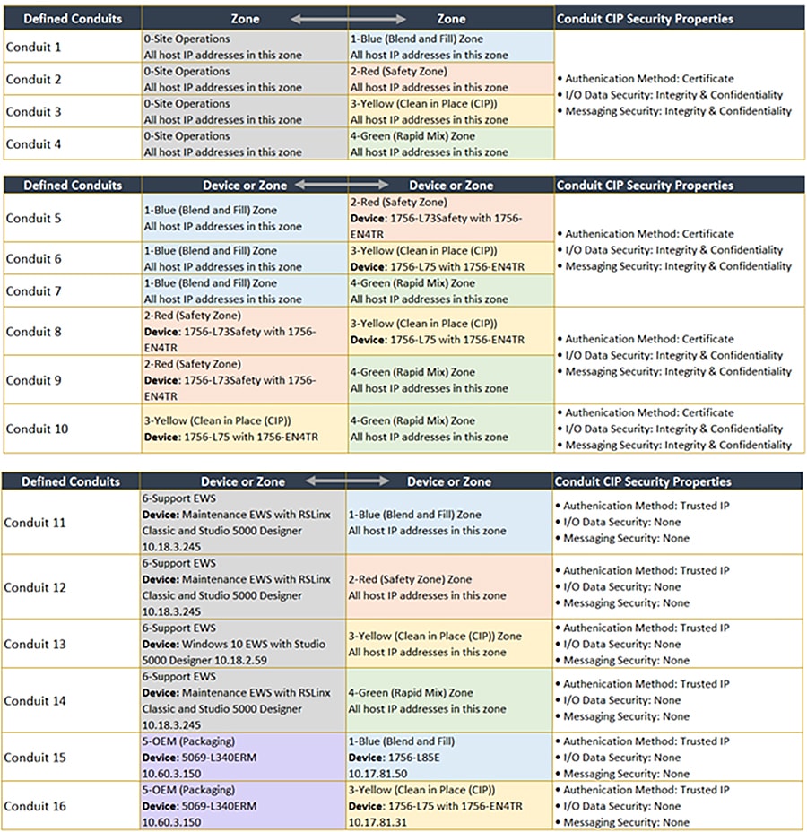
When CIP Security is enabled, only IACS devices within zones or an explicitly configured conduit are capable of establishing communications with other IACS devices in the security model. Conduits control access to and from different zones. Any CIP communication between zones must be through a defined conduit. Other IACS devices not in the same zone or explicitly configured with a conduit will be blocked.
Figure 3-2 shows the CPwE CIP Security model conduits. CIP Security properties will also be applied at the conduit component for inter-zone communications. The security properties applied are based on functional and security requirements obtained from the security risk assessment process. Each organization’s functional and security requirements will vary based on their own security risk assessments.
Figure 3-2 Conduits in the CPwE CIP Security Model
Note Non-CIP Security capable IACS devices can be added to the security model. These IACS devices will have a yellow triangle information icon displayed next to them in the center Content pane and the same icon stating Incompatible devices with zone beneath each security configuration option. These IACS devices will not receive CIP Security policy themselves. However, the CIP Security capable IACS devices will implicitly add the IP address of the non-CIP Security capable IACS devices to their Trusted IP list so that communication between the IACS devices can occur.
 Incompatible devices in zone.
Planning and Component Considerations
Implementing a CIP Security model requires preparation and planning before deployment. At a minimum, gather this information:
- Number of zones —When planning for security in a new system (greenfield) or redesign of an existing system (brownfield), the first step is to break the system into different zones and define conduits connecting these zones where necessary.
- Security requirements for each zone and conduit —Once a zone model of the system is established each zone and conduit is assigned a SL-T, based on a consequence analysis, which describes the desired security assurance for the respective zone or conduit. Determine the security requirements for the communication in the intra-zone and inter-zones:
–![]() Device identity/authentication
Device identity/authentication
–![]() Data integrity/authentication
Data integrity/authentication
–![]() Data confidentiality (encryption)
Data confidentiality (encryption)
- IACS devices assigned to each zone —IACS devices are the modules, drives, controllers, HMI panels, computers, and servers that work together to create an IACS network. FactoryTalk Policy Manager will allow adding IACS devices and software that do not support CIP Security in the security model. However, they are not able utilize any of the CIP Security properties including device or data identity/authentication and encrypting communications.
Next describe the functionality that should be provided by assets in a zone and the connections between zones to meet the security objectives. If certain legacy IACS devices do not satisfy a specific CR of the overall zone or SR, then additional security measures should be taken as described in the defense-in-depth concept.
–![]() Zones and zones or IACS devices
Zones and zones or IACS devices
FactoryTalk Policy Manager Configuration
Step 1![]() Validate all communication, processes, and programs are running as expected without CIP Security enabled, including:
Validate all communication, processes, and programs are running as expected without CIP Security enabled, including:
Verify the computer hosting FactoryTalk Policy Manager has successful communications to all required IACS devices, which include but is not limited to:
- Ping
- Tracert (Microsoft Windows), Traceroute (Cisco IOS, e.g., Allen-Bradley IES)
- Successfully discovered in FactoryTalk Linx Browser utility or FactoryTalk Linx in the Administration Console.
Note![]() CIP Security IACS devices must be discoverable by FactoryTalk Linx to apply and deploy CIP Security properties. FactoryTalk Linx Browser utility cannot be used to modify, enable, or disable the CIP Security properties on IACS devices. Use the FactoryTalk Policy Manager software to modify, enable, or disable CIP Security properties.
CIP Security IACS devices must be discoverable by FactoryTalk Linx to apply and deploy CIP Security properties. FactoryTalk Linx Browser utility cannot be used to modify, enable, or disable the CIP Security properties on IACS devices. Use the FactoryTalk Policy Manager software to modify, enable, or disable CIP Security properties.
Step 2![]() Log in and navigate to FactoryTalk Policy Manager.
Log in and navigate to FactoryTalk Policy Manager.
FactoryTalk Policy Manager Tool user accounts for login can be created in FactoryTalk Administration Console as FactoryTalk user or Windows-linked users. Specific access rights in FactoryTalk Policy Manager can be implemented in built-in security groups in FactoryTalk Administration Console.
Note FactoryTalk Policy Manager must be able to connect to FactoryTalk System Services to log in successfully. If the error message FactoryTalk System Services Cannot Be Reached appears after launching FactoryTalk Policy Manager, it means FactoryTalk System Services is not running. Select EXIT POLICY MANAGER to close the error message.
To resolve this error, attempt to start FactoryTalk System Services.
- Go to the Windows Services snap-in (services.msc).
- In the services list, scroll down to the FactoryTalk System Services item.
- Right-click FactoryTalk System Services and select Start.
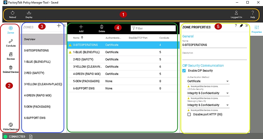
Table 3-2 provides a reference to the FactoryTalk Policy Manager navigation shown in Figure 3-3.
Figure 3-3 FactoryTalk Policy Manager Navigation
Zones identify a group of logical or physical IACS devices to which security settings are applied. IACS devices are added to zones.
Zones establish the rules for data integrity, data confidentially, and the authentication method used to authenticate trusted IACS devices. Once an IACS device is added to a zone, it will use the security properties configured on the zone for intra-zone communications with other IACS devices within that zone.
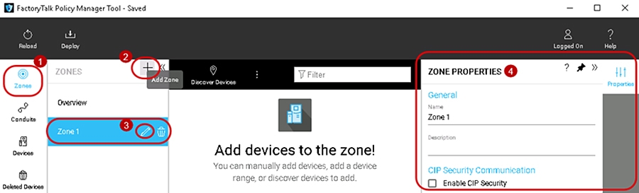
To add a zone to the security model follow the steps below (Figure 3-4)
1.![]() The left navigation bar contains the components for selection, to select the Zones component, click Zones.
The left navigation bar contains the components for selection, to select the Zones component, click Zones.
2.![]() Once the Zones component is selected, the left ZONES list pane will automatically appear and display an overview of the exiting zones. To create a Zone, click the + icon in the ZONES list pane. A new Zone 1 will appear under the ZONES list pane and the ZONE PROPERTIES pane will appear on the right side of the tool.
Once the Zones component is selected, the left ZONES list pane will automatically appear and display an overview of the exiting zones. To create a Zone, click the + icon in the ZONES list pane. A new Zone 1 will appear under the ZONES list pane and the ZONE PROPERTIES pane will appear on the right side of the tool.
3.![]() To configure or edit zones in the ZONES list, click to select the desired zone, then click the edit pencil icon in that zone.
To configure or edit zones in the ZONES list, click to select the desired zone, then click the edit pencil icon in that zone.
4.![]() The ZONE PROPERTIES pane will appear on the right side of the tool. Complete the configurations in the ZONE PROPERTIES pane according to the security requirements for intra-zone EtherNet/IP communications. See editable configuration fields in Table 3-3 .
The ZONE PROPERTIES pane will appear on the right side of the tool. Complete the configurations in the ZONE PROPERTIES pane according to the security requirements for intra-zone EtherNet/IP communications. See editable configuration fields in Table 3-3 .
Figure 3-4 Add a Zone to the Security Model
The ZONE PROPERTIES pane includes the editable configuration fields shown in Table 3-3 .
 Incompatible devices in zone.
 Incompatible devices in zone.
 Incompatible devices in zone.
 Incompatible devices in zone.
 Incompatible devices in zone.
IACS devices are the modules, drives, controllers, HMI panels, computers, and servers that work together to create a FactoryTalk system. They can be added to the security model in the Zones component or the Devices component. They can also be added manually or discovered by querying the network.
IACS devices added directly into a Zones component and will comply with security properties configured for the zone in the ZONE PROPERTIES pane. When added directly into the Devices component, they will be initially unassigned but can be easily moved to a zone using the PORT PROPERTIES pane.
Note![]() To add IACS devices using the Discover Devices button, the CIP Security IACS devices must be discoverable by FactoryTalk Linx.
To add IACS devices using the Discover Devices button, the CIP Security IACS devices must be discoverable by FactoryTalk Linx.
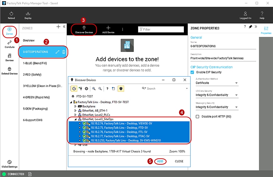
To add a Discovered Device to a Zones component in the security model follow the steps below (Figure 3-5).
1.![]() In the FactoryTalk Policy Manager left navigation bar, click Zones to select the Zones component.
In the FactoryTalk Policy Manager left navigation bar, click Zones to select the Zones component.
2.![]() Once the Zones component is selected, the left ZONES list pane will appear and display an overview of the exiting zones. Click the desired zone in the ZONES list pane.
Once the Zones component is selected, the left ZONES list pane will appear and display an overview of the exiting zones. Click the desired zone in the ZONES list pane.
3.![]() Click the Discover Devices button in the center Content pane, to open the Discover Devices window with FactoryTalk Linx.
Click the Discover Devices button in the center Content pane, to open the Discover Devices window with FactoryTalk Linx.
Use the Discover Devices button to traverse the FactoryTalk system and find IACS devices. Discovery can be useful for populating a list of devices or for checking that the devices added to the list manually are accurately identified.
4.![]() To select multiple IACS devices in the Discover Devices window, click to select a device then hold down the SHIFT key and click to select more IACS devices.
To select multiple IACS devices in the Discover Devices window, click to select a device then hold down the SHIFT key and click to select more IACS devices.
5.![]() Once one or more desired IACS devices are selected, the ADD button will become enabled and add those devices to the desired zone.
Once one or more desired IACS devices are selected, the ADD button will become enabled and add those devices to the desired zone.
Figure 3-5 Add an IACS Device to a Zone Using the Discovered Device Feature
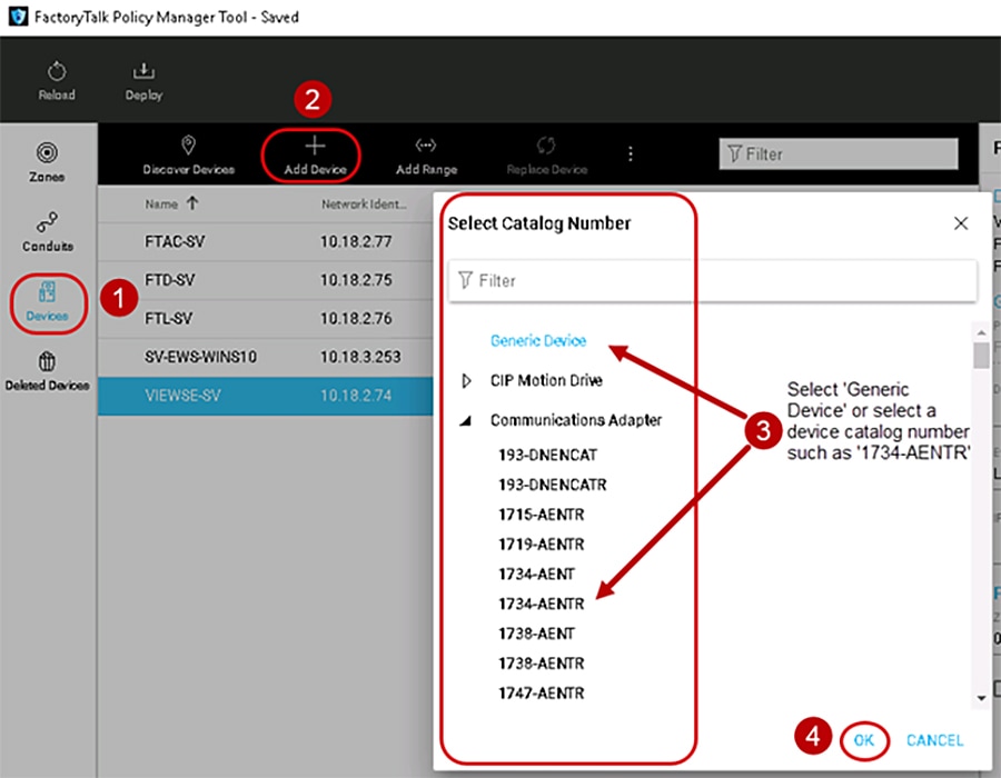
To manually add an IACS device to the Devices component in the security model follow the steps below (Figure 3-6)
1.![]() In the FactoryTalk Policy Manager left navigation bar, click Devices to select the Devices component.
In the FactoryTalk Policy Manager left navigation bar, click Devices to select the Devices component.
2.![]() Click the Add Device [ + ] button located in the center Content pane, to open the Select Catalog Number window.
Click the Add Device [ + ] button located in the center Content pane, to open the Select Catalog Number window.
Use the Add Device [ + ] button to manually add an IACS device to the current Devices component by selecting Generic Device or the catalog number of an IACS device. IACS devices added using the manual method requires the computer hosting FactoryTalk Policy Manager. This will achieve successful communications to the manually added IACS device.
3.![]() In the Select Catalog Number window, select either Generic Device or the catalog number of an IACS device.
In the Select Catalog Number window, select either Generic Device or the catalog number of an IACS device.
The Generic Device allows for adding IACS devices such as computers Windows Server 2016 hosting the networking management software FactoryTalk Network Manager.
4.![]() Once the desired IACS device has been selected, click OK.
Once the desired IACS device has been selected, click OK.
The Select Catalog Number window will only allow the selection of one IACS device. If more IACS devices are required to be manually added, repeat steps 1-4 of this section.
Figure 3-6 Manually Add an IACS Device to Devices Component
Step 5![]() Verify and update the Device Properties.
Verify and update the Device Properties.
1.![]() The first time a device is added using either methods discovered or manually added to the Zones or Devices components, the DEVICE PROPERTIES pane will automatically appear on the right-hand side of the tool (Figure 3-7).
The first time a device is added using either methods discovered or manually added to the Zones or Devices components, the DEVICE PROPERTIES pane will automatically appear on the right-hand side of the tool (Figure 3-7).
2.![]() The DEVICE PROPERTIES pane will always appear on the right side of the tool and is used to add/edit pertinent information about the IACS device. See editable configuration fields in Table 3-4 .
The DEVICE PROPERTIES pane will always appear on the right side of the tool and is used to add/edit pertinent information about the IACS device. See editable configuration fields in Table 3-4 .
Note![]() If an administrator navigates away to another component or IACS device, then reselects the desired IACS device in the center Content pane, it will now automatically appear in the PORT PROPERTIES to the right of the tool instead of the DEVICE PROPERTIES. The administrator can easily bring up the DEVICE PROPERTIES pane by selecting the pencil icon next to the Device field in the PORT PROPERTIES pane (Figure 3-8).
If an administrator navigates away to another component or IACS device, then reselects the desired IACS device in the center Content pane, it will now automatically appear in the PORT PROPERTIES to the right of the tool instead of the DEVICE PROPERTIES. The administrator can easily bring up the DEVICE PROPERTIES pane by selecting the pencil icon next to the Device field in the PORT PROPERTIES pane (Figure 3-8).
Figure 3-7 Device Properties in FactoryTalk Policy Manager
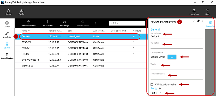
The DEVICE PROPERTIES pane includes the editable configuration fields shown in Table 3-4 .
Step 6![]() Verify and Update the Port Properties.
Verify and Update the Port Properties.
A port represents a physical socket of an IACS device that allows communication with another IACS device using CIP Security. FactoryTalk Linx and IACS devices identified by catalog number have only a single port associated with IP addresses, ports, and protocols. IACS devices that have a specific catalog number have a predefined number of ports with assigned protocols. If an IACS device does not have a catalog number FactoryTalk Policy Manager adds it as a Generic Device. When a security policy model includes generic devices, configure the number of ports on the IACS device.
1.![]() Whether devices were discovered or manually added to the Zones or Devices components, the PORT PROPERTIES pane can be accessed by clicking and selecting the device in the center Content pane. (Figure 3-8).
Whether devices were discovered or manually added to the Zones or Devices components, the PORT PROPERTIES pane can be accessed by clicking and selecting the device in the center Content pane. (Figure 3-8).
2.![]() The PORT PROPERTIES pane will always appear on the right side of FactoryTalk Policy Manager and is used to add pertinent information about the IACS device. See editable configuration fields in Table 3-5 .
The PORT PROPERTIES pane will always appear on the right side of FactoryTalk Policy Manager and is used to add pertinent information about the IACS device. See editable configuration fields in Table 3-5 .
Figure 3-8 Port Properties in FactoryTalk Policy Manager
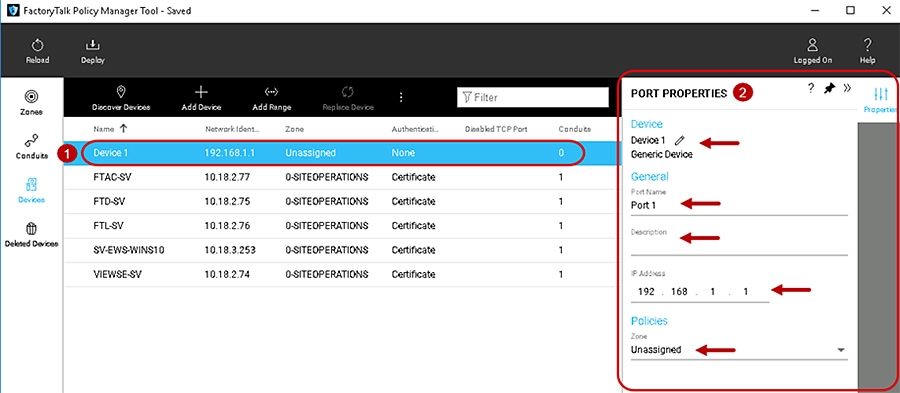
The PORT PROPERTIES pane includes the editable configuration fields shown in Table 3-5 .
Conduits create trusted communication pathways outside of zones. Conduits require two endpoints, such as:
- Two different zones for a zone to zone conduit.
- Two IACS from different zones for a device to device conduit.
- A zone and an IACS device from another zone for a zone to device conduit.
Endpoints can be either a zone or an IACS device. Conduits must adhere to these rules:
- Each combination of endpoints must be unique.
- Duplicate conduits are not permitted.
- One of the endpoints must be CIP Security capable.
- If one endpoint is a zone, the other endpoint cannot be a device within that zone.
Conduits support two authentication methods:
- Trusted IP—Assigns a trust relationship to an asset based on its IP address.
- Certificate—Establishes the identity of the IACS device by using a certificate from a trusted authority. This enables configuration of integrity and confidentiality options for communication over the conduit using the public key associated with the certificate.
Note![]() Non-CIP Security capable IACS devices can be added to a zone with CIP Security enabled. These IACS devices will have a yellow triangle information icon displayed next to them in the center Content pane. These IACS devices will not be able to use certificate for communication for the conduits. When a conduit is created for the zone to another zone with the authentication method of certificate, the CIP Security capable IACS devices will implicitly trust the non-CIP Security capable IACS devices using Trusted IP.
Non-CIP Security capable IACS devices can be added to a zone with CIP Security enabled. These IACS devices will have a yellow triangle information icon displayed next to them in the center Content pane. These IACS devices will not be able to use certificate for communication for the conduits. When a conduit is created for the zone to another zone with the authentication method of certificate, the CIP Security capable IACS devices will implicitly trust the non-CIP Security capable IACS devices using Trusted IP.
To add a conduit in the security model, follow the steps below (Figure 3-9).
1.![]() The left navigation bar contains the components for selection. To select the Conduits component, click Conduits.
The left navigation bar contains the components for selection. To select the Conduits component, click Conduits.
2.![]() Once the Conduits component is selected, the center Content pane will display a toolbar that contains the actions available and an overview of the Conduits concepts. To create a conduit, click the Add [ + ] icon in the center Content pane toolbar.
Once the Conduits component is selected, the center Content pane will display a toolbar that contains the actions available and an overview of the Conduits concepts. To create a conduit, click the Add [ + ] icon in the center Content pane toolbar.
3.![]() The CONDUIT PROPERTIES pane will appear on the right side of the tool.
The CONDUIT PROPERTIES pane will appear on the right side of the tool.
4.![]() In the CONDUIT PROPERTIES pane, configure or edit Endpoint 1 for the conduit by selecting the first Select an endpoint field ellipsis [...].
In the CONDUIT PROPERTIES pane, configure or edit Endpoint 1 for the conduit by selecting the first Select an endpoint field ellipsis [...].
5.![]() The Select Endpoint window will appear.
The Select Endpoint window will appear.
6.![]() Select either a zone or expand a zone to select an IACS device as the first endpoint of the conduit.
Select either a zone or expand a zone to select an IACS device as the first endpoint of the conduit.
7.![]() Once the desired endpoint is selected, the OK button will become enabled. Click OK.
Once the desired endpoint is selected, the OK button will become enabled. Click OK.
8.![]() Return to the CONDUIT PROPERTIES pane, configure or edit Endpoint 2 for the conduit by selecting the second Select an endpoint field ellipsis [...], and perform the same steps in 6 and 7 to select a second endpoint of the conduit. Remember to adhere to the conduit rules when selecting the second endpoint.
Return to the CONDUIT PROPERTIES pane, configure or edit Endpoint 2 for the conduit by selecting the second Select an endpoint field ellipsis [...], and perform the same steps in 6 and 7 to select a second endpoint of the conduit. Remember to adhere to the conduit rules when selecting the second endpoint.
9.![]() Complete the endpoint configuration for Conduit 1 in the CONDUIT PROPERTIES pane by clicking NEXT.
Complete the endpoint configuration for Conduit 1 in the CONDUIT PROPERTIES pane by clicking NEXT.
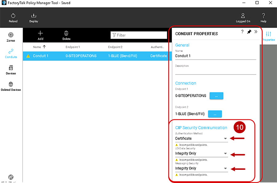
10.![]() Once the endpoints have been configured, the conduit CIP Security Communication area will appear in the CONDUIT PROPERTIES pane (Figure 3-10). CIP Security Communication area will have the configuration options for how endpoints will apply security for communication in the conduit. See editable configuration fields in Table 3-6 .
Once the endpoints have been configured, the conduit CIP Security Communication area will appear in the CONDUIT PROPERTIES pane (Figure 3-10). CIP Security Communication area will have the configuration options for how endpoints will apply security for communication in the conduit. See editable configuration fields in Table 3-6 .
Figure 3-9 Add a Conduit to the Security Model
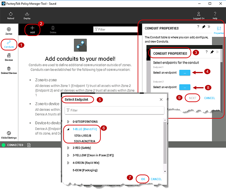
Figure 3-10 Conduit Properties in the Security Model
 Incompatible devices in zone.
 Incompatible devices in zone.
After the zones, conduits, and devices have been configured, the security policy model can be deployed. It is recommended to schedule downtime or maintenance window when deploying a CIP Security model to an IACS network. Before a deployed security policy becomes active, communications must be reset on configured IACS devices, resulting in a short loss of connectivity. The schedule downtime or maintenance window will also allow time for any troubleshooting if needed.
Before deploying a security model, make sure that all devices are operational and have network access.
There are two deployment options for security policy model deployment:
When this option is selected, the communication port will be closed and reopened on the IACS device during the deployment process. Similar to resetting the network card on a computer, the IACS device stays functional but is disconnected from the network for a few moments. Using this option applies the new policy to the IACS device and deploys it simultaneously.
- After deployment —Deploying the changes without resetting the communication channel so that the reset can occur at another time than the deployment process.
When this option is selected, the security policy settings will be deployed to the IACS device but are not in effect. The communications ports must be reset before the security policy will be used. This option is useful if there is a scheduled maintenance reset process in your environment that can be relied upon to perform this function.
Once the model is deployed and communications reset on IACS devices, those IACS devices will only accept communications from other IACS devices in the same zone or using conduits configured to enable communications with other security zones or devices.
If changes are made to the security model in FactoryTalk Policy Manager after it is deployed, an asterisk (*) will appear next to the IACS device, indicating that the configured policy has not been deployed to that IACS device.
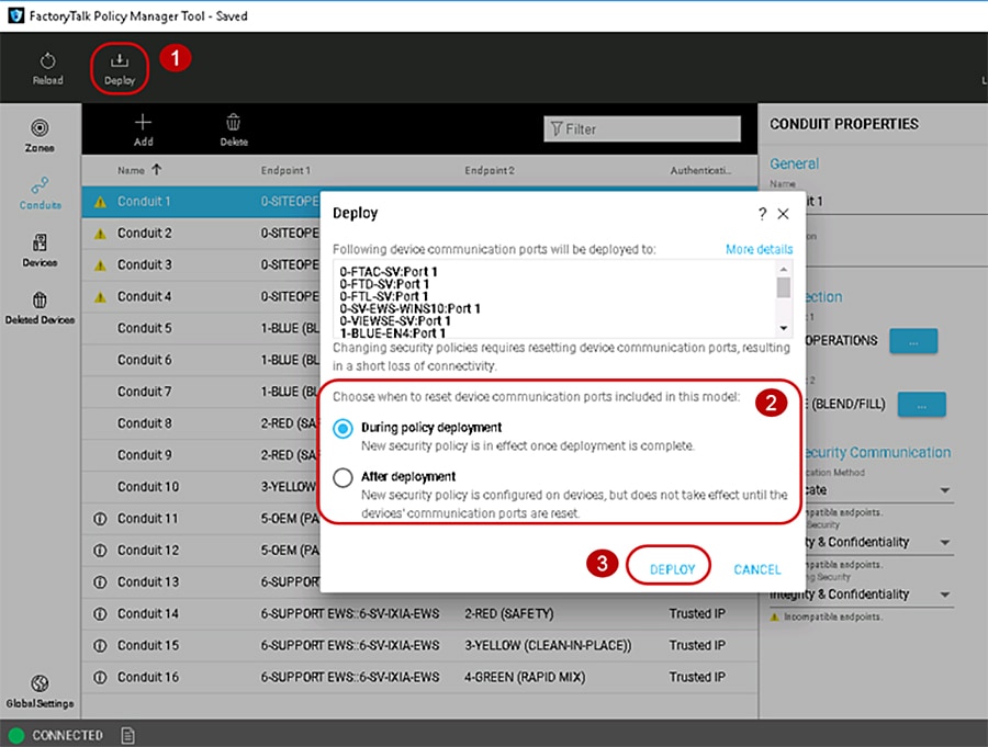
To deploy the security model, use the following steps (Figure 3-11)
1.![]() In the FactoryTalk Policy Manager top main menu bar, click Deploy.
In the FactoryTalk Policy Manager top main menu bar, click Deploy.
2.![]() In the Deploy window that appears, under the section Choose when to reset device communication ports included in this model: make a deployment selection:
In the Deploy window that appears, under the section Choose when to reset device communication ports included in this model: make a deployment selection:
–![]() During deployment —Immediate resetting of the IACS device(s) communication ports as part of deployment.
During deployment —Immediate resetting of the IACS device(s) communication ports as part of deployment.
–![]() After deployment —No resetting of one or more IACS devices communication ports at the time of the deployment. The security policy settings will be deployed to the IACS device but are not in effect until the communications ports are reset on the IACS device.
After deployment —No resetting of one or more IACS devices communication ports at the time of the deployment. The security policy settings will be deployed to the IACS device but are not in effect until the communications ports are reset on the IACS device.
Note![]() Before a deployed security policy becomes active, communications must be reset on the port of the configured IACS devices.
Before a deployed security policy becomes active, communications must be reset on the port of the configured IACS devices.
3.![]() Once a deployment method has been selected, the DEPLOY button will become enabled for selection. Click the DEPLOY button.
Once a deployment method has been selected, the DEPLOY button will become enabled for selection. Click the DEPLOY button.
Figure 3-11 Deploy the Security Model
The deployment process may take several minutes to complete depending on the size of the network. Once deployment is complete a summary report is provided listing the successes, failures, and errors encountered during the process.

Warning![]() If the deployment process is interrupted or stopped during deploy, this can leave the system in an unexpected state. Communications between IACS devices could be permanently interrupted requiring module factory reset.
If the deployment process is interrupted or stopped during deploy, this can leave the system in an unexpected state. Communications between IACS devices could be permanently interrupted requiring module factory reset.
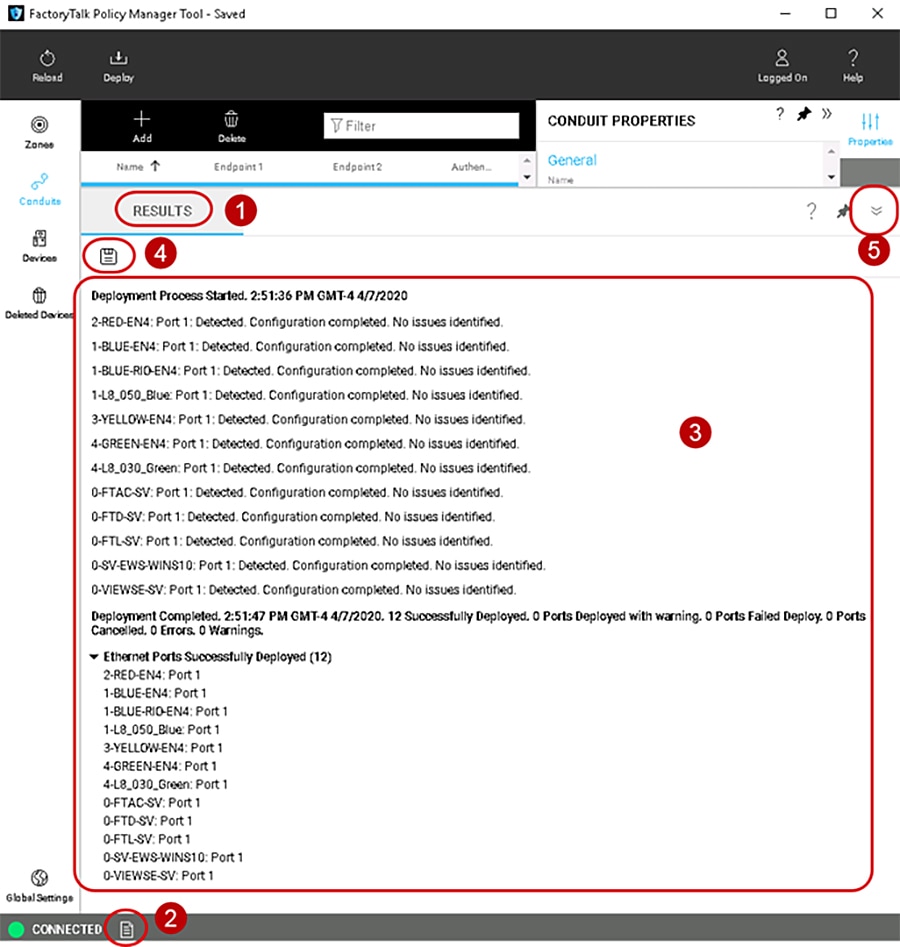
See the Results pane for displayed updates with the results of the deployment as it occurs and complete a summary report (Figure 3-12).
1.![]() The Results pane will automatically appear after DEPLOY has been selected.
The Results pane will automatically appear after DEPLOY has been selected.
2.![]() If the Results pane does not appear, at the bottom of the tool next to the CONNECTED, press the paper icon to bring up the Results pane.
If the Results pane does not appear, at the bottom of the tool next to the CONNECTED, press the paper icon to bring up the Results pane.
3.![]() In the body of the Results pane, review the result of the deployment on each item in the model. The possible results are:
In the body of the Results pane, review the result of the deployment on each item in the model. The possible results are:
–![]() Configuration complete. No issues identified.
Configuration complete. No issues identified.
–![]() Configuration complete. Warnings identified.
Configuration complete. Warnings identified.
–![]() Configuration not complete. Error identified.
Configuration not complete. Error identified.
4.![]() Select the save icon to save the Results pane output for reference, reporting, or other record keeping requirements.
Select the save icon to save the Results pane output for reference, reporting, or other record keeping requirements.
5.![]() Select the down arrow icon to minimize the Results pane.
Select the down arrow icon to minimize the Results pane.
Figure 3-12 Results of the Deployment of the Security Model
Removing the CIP Security Policy from an IACS Device
If the security model has been deployed and the IACS device communications have been reset the IACS device is constrained by the security policy. Deleting the IACS device from the model does not remove the security configuration. Even if FactoryTalk Policy Manager and FactoryTalk System Services are uninstalled, the security policy configured for the IACS device is still in effect.
To remove CIP Security properties from an IACS device, use the PORT PROPERTIES pane in the security model and follow the steps below (Figure 3-13). The steps described in this section are the recommended method to remove any CIP Security configurations on an IACS device. It also assumes the CIP Security enabled IACS device still has successful communications with the computer hosting FactoryTalk Policy Manager and FactoryTalk System Services.
1.![]() The PORT PROPERTIES pane can be accessed in either the Zones or Devices components.
The PORT PROPERTIES pane can be accessed in either the Zones or Devices components.
2.![]() Select the desired IACS device for removing of CIP Security properties by clicking the IACS device from the center Content pane.
Select the desired IACS device for removing of CIP Security properties by clicking the IACS device from the center Content pane.
3.![]() The PORT PROPERTIES pane will appear on the right side of FactoryTalk Policy Manager. The settings under the Policies area in the Zone drop-down field will display the name of the current zone to which the IACS device port is assigned. In the drop-down reassign the port to Unassigned. Selecting the Unassigned from the Zones drop down field will remove the selected port from the zone it was previously assigned to as well as the CIP Security properties: Authentication Method, I/O Data Security, and Messaging Security.
The PORT PROPERTIES pane will appear on the right side of FactoryTalk Policy Manager. The settings under the Policies area in the Zone drop-down field will display the name of the current zone to which the IACS device port is assigned. In the drop-down reassign the port to Unassigned. Selecting the Unassigned from the Zones drop down field will remove the selected port from the zone it was previously assigned to as well as the CIP Security properties: Authentication Method, I/O Data Security, and Messaging Security.
4.![]() In the FactoryTalk Policy Manager top main menu bar, click Deploy.
In the FactoryTalk Policy Manager top main menu bar, click Deploy.
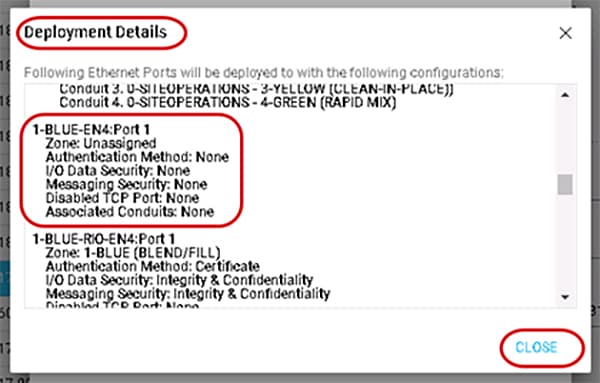
5.![]() (Optional) The Deploy window will appear. Select the More details link to view the Deployment Details popup window.
(Optional) The Deploy window will appear. Select the More details link to view the Deployment Details popup window.
The Deployment Details window will verify one or more IACS devices and the new CIP Security properties that will be set on the next deployment of the security model. Click CLOSE to go exit the Deployment Details window (Figure 3-14).
6.![]() In the Deploy window that appears, under the section Choose when to reset device communication ports included in this model: make a deployment selection:
In the Deploy window that appears, under the section Choose when to reset device communication ports included in this model: make a deployment selection:
–![]() During deployment —Immediate resetting of one or more IACS devices communication ports as part of deployment.
During deployment —Immediate resetting of one or more IACS devices communication ports as part of deployment.
–![]() After deployment —No resetting of the IACS device(s) communication ports at the time of the deployment. The security policy settings will be deployed to the IACS device but are not in effect until the communications ports are reset on the IACS device.
After deployment —No resetting of the IACS device(s) communication ports at the time of the deployment. The security policy settings will be deployed to the IACS device but are not in effect until the communications ports are reset on the IACS device.
7.![]() Click the DEPLOY button to start the deployment.
Click the DEPLOY button to start the deployment.
Verify in the Results pane for a successful deployment of all IACS device ports.
Figure 3-13 Remove the CIP Security Policy from an IACS Device
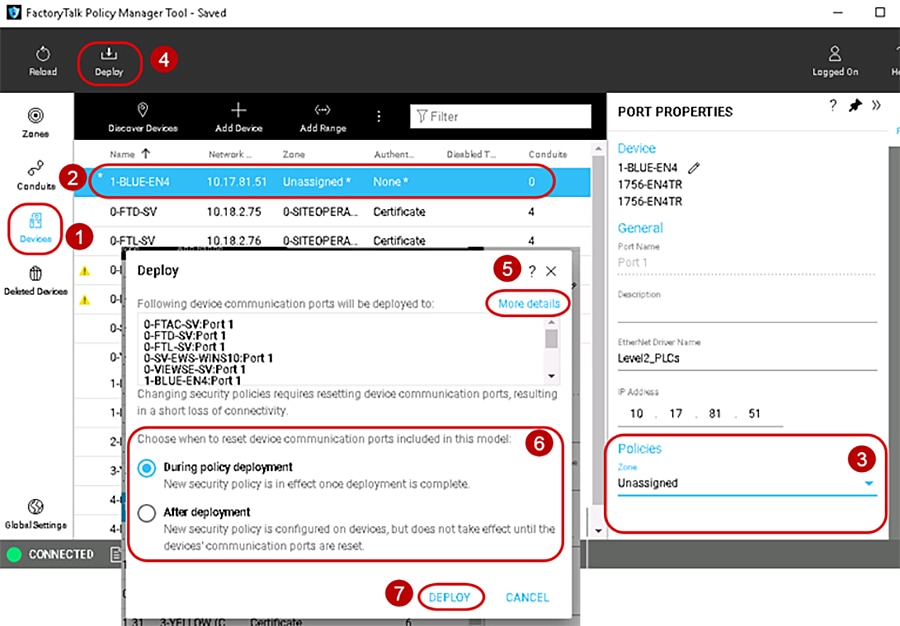
Figure 3-14 Deployment Details Window
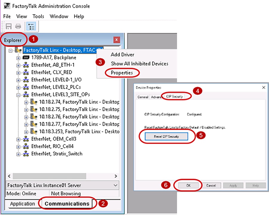
If the CIP Security enabled IACS device can no longer communicate with the computer hosting FactoryTalk Policy Manager and FactoryTalk System Services use the following methods:
- Use the FactoryTalk Administration Console to remove the CIP Security policy configuration from FactoryTalk Linx, then return to FactoryTalk Policy Manager to delete the device with FactoryTalk Linx and redeploy the model to the other IACS devices to update their trust models. Figure 3-15 details the steps:
1.![]() Open the FactoryTalk Administration Console application and make sure the Explorer pane is visible.
Open the FactoryTalk Administration Console application and make sure the Explorer pane is visible.
2.![]() At the bottom of the Explorer pane, click Communications tab.
At the bottom of the Explorer pane, click Communications tab.
3.![]() Right click the top instance FactoryTalk Linx - Desktop, < computer name > and select Properties from the menu.
Right click the top instance FactoryTalk Linx - Desktop, < computer name > and select Properties from the menu.
4.![]() The Device Properties window will appear. Select the CIP Security tab.
The Device Properties window will appear. Select the CIP Security tab.
5.![]() Select the Reset CIP Security button. A popup window will appear to confirm.
Select the Reset CIP Security button. A popup window will appear to confirm.
6.![]() Click OK on the Device Properties window to close.
Click OK on the Device Properties window to close.
- For the 1756-EN4TR and the 1756-L85E, use the factory reset method documented in the user manuals found in Additional Resources in Chapter2, “CPwE CIP Security Design Considerations”
Figure 3-15 FactoryTalk Administration Console Removal of CIP Security
Replacing an IACS Device in the Security Model
Replacing an IACS device is used when an IACS device that has already been configured and enabled for CIP Security has failed or needs to be rotated out for maintenance. Device replacement button enables the identity and the security configuration of the previous device to be assigned to the replacement IACS device. The communications port on an IACS device must be reset after replacement to apply the security policy settings.
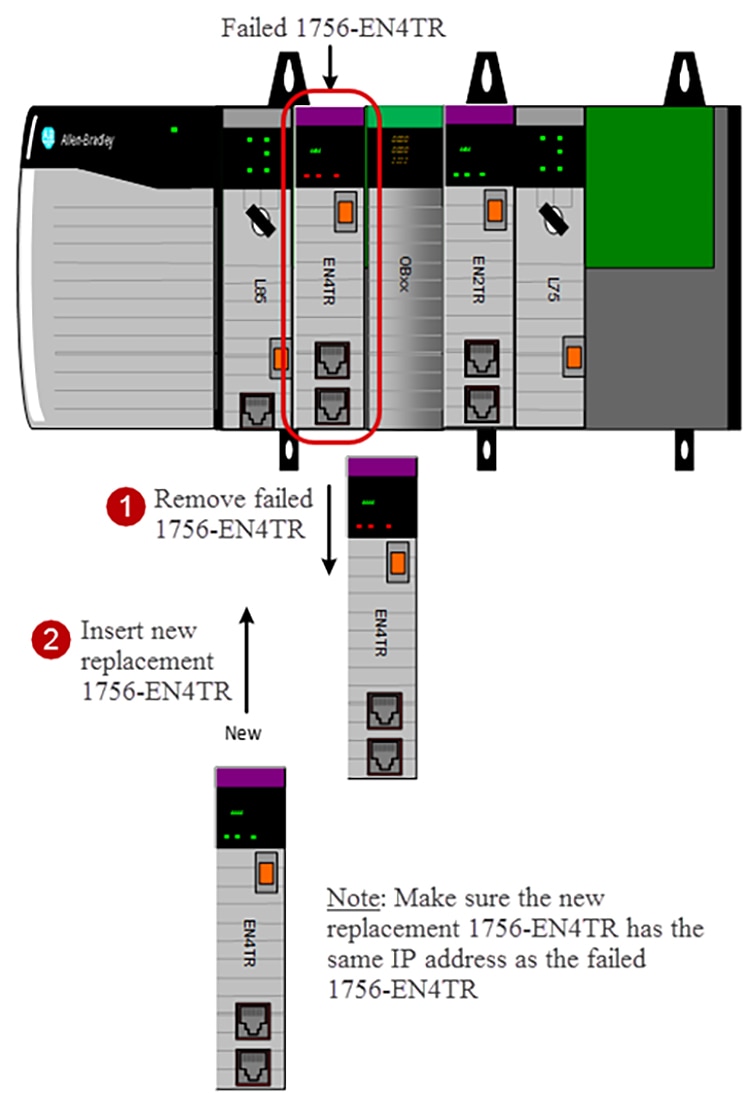
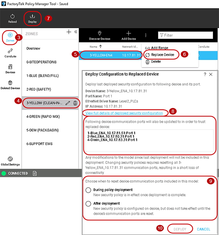
To replace an IACS device, use the Replace Device ( P) button in the security model. Follow the steps below (Figure 3-16):
1.![]() Physically remove the failed IACS device from the network.
Physically remove the failed IACS device from the network.
2.![]() Physically insert the new replacement IACS device into the network.
Physically insert the new replacement IACS device into the network.
Make sure the new replaced IACS device has the same IP address as the failed IACS device.
3.![]() In the FactoryTalk Policy Manager too, the Replace Device ( P) button can be accessed in either the Zones or Devices components.
In the FactoryTalk Policy Manager too, the Replace Device ( P) button can be accessed in either the Zones or Devices components.
4.![]() In the Zones component, select the Zone in which the failed IACS device resides.
In the Zones component, select the Zone in which the failed IACS device resides.
5.![]() Select the desired IACS device for replacement by clicking the IACS device from the center Content pane.
Select the desired IACS device for replacement by clicking the IACS device from the center Content pane.
6.![]() In the center Content pane toolbar, click the Replace Device ( P) button.
In the center Content pane toolbar, click the Replace Device ( P) button.
7.![]() In the FactoryTalk Policy Manager top main menu bar, click the Deploy button.
In the FactoryTalk Policy Manager top main menu bar, click the Deploy button.
8.![]() The Deploy Configuration to Replaced Device window will display a list of device communication ports that will also be updated to trust replaced device.
The Deploy Configuration to Replaced Device window will display a list of device communication ports that will also be updated to trust replaced device.
(Optional) Select the View full details of deployed security configuration link to view details of device communication ports that will be updated to trust the replaced device popup window.
9.![]() In the Deploy Configuration to Replaced Device window under the section Choose when to reset device communication ports included in this model: make a deployment selection:
In the Deploy Configuration to Replaced Device window under the section Choose when to reset device communication ports included in this model: make a deployment selection:
During deployment —Immediate resetting of the IACS devices communication ports as part of deployment.
After deployment —No resetting of the IACS devices communication ports at the time of the deployment. The security policy settings will be deployed to the IACS device but are not in effect until the communications ports are reset on the IACS device.
10.![]() Click the DEPLOY button to start the deployment.
Click the DEPLOY button to start the deployment.
Verify in the Results pane for a successful deployment of all IACS device ports.
Figure 3-16 Replace Failed IACS Device in Network
 Feedback