Cisco SD-WAN Starlink LEO Satellite CVD
Available Languages
Bias-Free Language
The documentation set for this product strives to use bias-free language. For the purposes of this documentation set, bias-free is defined as language that does not imply discrimination based on age, disability, gender, racial identity, ethnic identity, sexual orientation, socioeconomic status, and intersectionality. Exceptions may be present in the documentation due to language that is hardcoded in the user interfaces of the product software, language used based on RFP documentation, or language that is used by a referenced third-party product. Learn more about how Cisco is using Inclusive Language.
- US/Canada 800-553-2447
- Worldwide Support Phone Numbers
- All Tools
 Feedback
 Feedback
Executive overview
The Non-Terrestrial Network era is changing how enterprises think about WAN resiliency. For decades, global connectivity strategies have depended primarily on terrestrial fiber, broadband, and cellular services. These transports remain foundational, but they share physical exposure to the same events: fiber cuts, regional power disruption, natural disasters, construction damage, and local infrastructure failures. When those risks affect an area, primary and backup terrestrial paths can fail together.
Satellite connectivity has long offered geographic diversity, but legacy geostationary satellite services introduced a major tradeoff. At approximately 35,786 km above Earth, GEO systems commonly experience round-trip latency in the 550–700 ms range, which limits their usefulness for latency-sensitive enterprise applications such as SD-WAN tunnels, voice, interactive SaaS, financial transactions, and real-time operational workloads.
Low Earth Orbit satellite networks change that equation. Operating much closer to Earth, LEO constellations can deliver round-trip latency commonly in the 25–60 ms range, making satellite transport practical for modern enterprise WAN use cases. LEO is no longer only a connectivity option for remote or underserved locations. It has become a geographically diverse resiliency layer for branches, hubs, mobile environments, temporary sites, and critical operations that cannot depend on terrestrial infrastructure alone.
The timing matters because LEO has moved from emerging technology to operational-scale service. Reusable launch systems have materially reduced the cost of placing satellites in orbit, enabling larger constellations, faster replenishment, and broader commercial availability. Starlink’s expanding satellite footprint, inter-satellite laser links, improved phased-array terminals, and denser ground gateway architecture have made low-latency satellite internet a realistic enterprise underlay rather than a niche backup option.
However, low-latency satellite internet by itself is not an enterprise WAN architecture. Enterprises still need segmentation, encryption, policy control, application-aware routing, security enforcement, operational visibility, and predictable integration with existing WAN designs. This is where Cisco adds the architecture required to turn Starlink transport into a secure, intelligent, and manageable enterprise fabric.
Cisco SD-WAN abstracts Starlink as one underlay within a broader transport strategy that can also include fiber, broadband, LTE, and 5G. Corporate traffic is carried through encrypted SD-WAN overlays, while policy determines how applications use available paths based on business intent, performance, and security requirements. This allows Starlink to provide physical path diversity while Cisco SD-WAN provides the control, protection, and optimization needed for production operations.
Key outcomes include:
● Resilient WAN transport that reduces dependency on terrestrial infrastructure
● Secure overlay tunneling across Starlink and traditional WAN transports
● Application-Aware Routing based on real-time loss, latency, and jitter
● QoS and App-QoE capabilities to manage variable satellite conditions
● Secure Direct Internet Access with local threat enforcement where applicable
● SSE integration with Cisco Secure Access or third-party security clouds
● Advanced designs for high availability, multi-terminal aggregation, and site-specific resiliency
● Support for stronger encryption models, including post-quantum-safe options on supported Cisco platforms
This CVD demonstrates how Cisco SD-WAN and Starlink can be integrated, secured, and optimized for enterprise deployment. It prepares readers to evaluate LEO not simply as another internet circuit, but as a strategic resiliency layer that becomes far more valuable when governed by Cisco’s WAN, security, and application experience.
LEO opportunity and business imperative
From legacy satellite to enterprise-ready LEO
Enterprise resiliency is entering a new phase. Traditional WAN designs have relied on terrestrial fiber, broadband, and cellular networks, with legacy satellite services used only when no other option was available. That model is changing. Low Earth Orbit connectivity now gives enterprises a practical way to add geographic diversity without accepting the high latency historically associated with geostationary satellite services.
Starlink provides this LEO capability as a high-capacity, low-latency internet underlay delivered through a standard Ethernet handoff. In an enterprise architecture, that underlay is not treated as a standalone network. It becomes one transport option within a broader Cisco SD-WAN fabric, alongside terrestrial circuits such as MPLS, broadband, LTE, or 5G.
Underlay, overlay, and enterprise control
The architectural principle is simple and important: the physical underlay is kept separate from the intelligent SD-WAN overlay. Starlink provides the end-to-end satellite path from the site, through the LEO constellation, to a ground gateway or point of presence where traffic reaches the internet. Cisco SD-WAN builds secure overlay tunnels across that transport, encrypting and policy-routing enterprise traffic without exposing private applications to the untrusted transit network.
This separation allows organizations to use LEO connectivity for business continuity while preserving the controls expected of an enterprise WAN. Applications do not need to understand the satellite path. They see a secure, policy-driven SD-WAN fabric that can steer traffic based on business intent, performance, and security requirements.
The architecture supports secure fabric connectivity to private data centers or regional hubs, Direct Internet Access for selected internet and SaaS traffic, and Secure Service Edge integration for cloud-delivered controls such as ZTNA, CASB, and DLP.
Business continuity across industries
The business imperative is clear: organizations need continuity across more locations, more industries, and more operating models than terrestrial networks alone can reliably support. Financial services require resilient branch and ATM connectivity. Healthcare providers need dependable access for telehealth and electronic health records. Retailers need point-of-sale continuity. Transportation and logistics teams need persistent connectivity across mobile and distributed environments.
LEO connectivity gives these industries a new path to resilience. Cisco SD-WAN makes that path enterprise-ready.
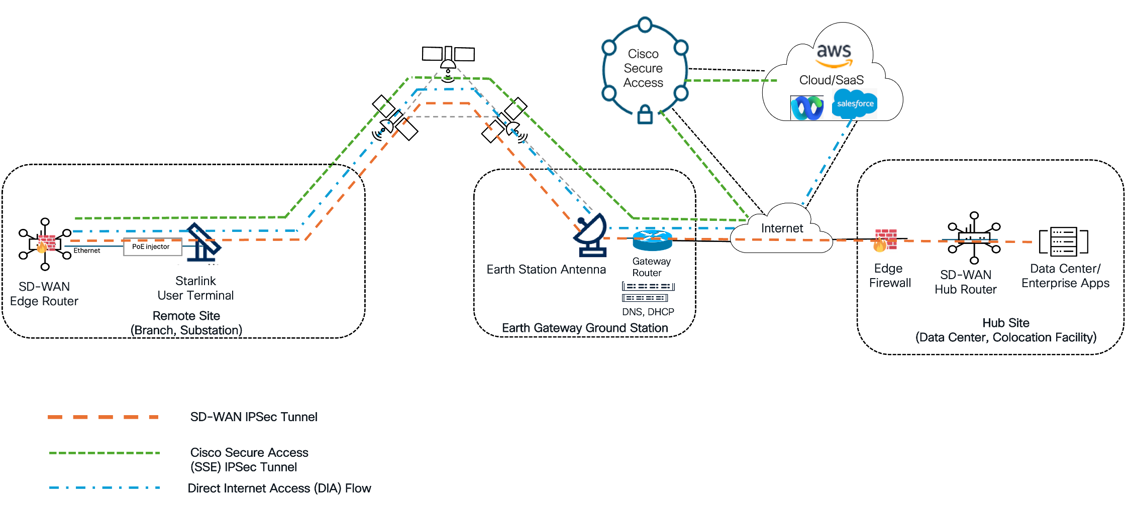
Cisco SD-WAN with Starlink
Starlink provides a high-capacity, low-latency LEO internet underlay through a standard Ethernet handoff. Cisco SD-WAN turns that transport into part of an enterprise WAN architecture by separating the physical satellite path from the secure overlay fabric. This allows organizations to use Starlink for resilient connectivity while keeping corporate traffic encrypted, segmented, policy-routed, and protected across an untrusted internet transport.
In the reference architecture, traffic from a branch, hub, mobile site, or temporary location traverses the Starlink terminal, the LEO constellation, and a Starlink ground gateway or point of presence before reaching the internet. Cisco Catalyst SD-WAN or Cisco Meraki SD-WAN then establishes secure overlay connectivity across that underlay, applying application steering, performance monitoring, security policy, and traffic segmentation according to business intent.
The architecture supports three primary traffic models: secure fabric connectivity to data centers, regional hubs, or cloud gateways; Direct Internet Access for selected internet and SaaS traffic with local security enforcement where applicable; and Secure Service Edge integration through Cisco Secure Access or third-party SSE platforms for controls such as ZTNA, CASB, DLP, and cloud-delivered threat protection.
The value of the combined architecture is that Starlink addresses transport diversity, while Cisco provides the enterprise control plane, security model, policy framework, and application intelligence required for production WAN operations. Key capabilities include SD-WAN overlay tunneling across Starlink and terrestrial transports, Application-Aware Routing based on real-time loss, latency, and jitter, QoS for variable satellite bandwidth, App-QoE features such as Forward Error Correction, packet duplication, TCP optimization, compression, and data redundancy elimination, secure DIA and SSE integration, Catalyst and Meraki deployment options, advanced Catalyst designs such as TLOC extension, high availability, multi-terminal aggregation, and supported post-quantum-safe encryption options where required.
This CVD focuses on the integration, security, and optimization of Starlink as a LEO underlay for Cisco SD-WAN. It covers Catalyst SD-WAN and Meraki SD-WAN design models, baseline implementation guidance, transport optimization, security integration, centralized policy design, and deployment profiles for different site types, including micro-sites, lean branches, resilient hubs, and high-capacity hubs.
The strategic outcome is a WAN architecture that is more resilient, geographically diverse, and operationally adaptable. By combining LEO connectivity with an intelligent and secure Cisco SD-WAN fabric, enterprises can reduce dependency on terrestrial infrastructure, improve continuity during outages, and extend trusted connectivity to locations and operating models that were previously difficult to serve.
Deployment guides
These guides present the implementation paths for using Starlink as a Cisco SD-WAN transport. The Catalyst guide provides the controller-driven workflow for enterprise transport, optimization, and policy; the Meraki guide provides the dashboard-driven workflow for MX onboarding, AutoVPN, security, and validation.
Catalyst SD-WAN LEO optimizations
This section provides a comprehensive framework for transforming Starlink’s LEO satellite service into a robust, managed enterprise transport. Whether integrating into an existing (brownfield) SD-WAN fabric or architecting a new (greenfield) deployment, the primary design objective is to achieve a predictable, enterprise-grade connection by combining appropriate terminal selection, a validated physical handoff, a stable base configuration, and policy-driven resiliency. By following this implementation-oriented workflow, engineers can establish a reliable transport foundation before layering on advanced performance, security, and optimization features in controlled, scalable stages.
Deployment scope and workflow
This guide outlines the end-to-end workflow for connecting Starlink low Earth orbit (LEO) satellite service to a Cisco Catalyst SD-WAN edge. It is designed to support a wide range of use cases, including fixed branches, temporary sites, mobile operations, maritime environments, and remote locations where Starlink serves as primary, secondary, or diversity transport. Because performance metrics, service-plan behaviors, and hardware capabilities vary by geography, subscription, and terminal generation, all specifications must be validated during the site design phase.
Scope limitations
This deployment guide focuses on IPv4-based SD-WAN transport configurations. While IPv6 dual-stack support is a critical component of modern network design, it is currently excluded from this scope and is slated for validation in future iterations of this guide.
Deployment workflow
1. Plan the deployment: select the Starlink service, terminal, Cisco edge platform, and transport role.
2. Install and validate the underlay: mount the terminal, provide power, connect Ethernet, and confirm Internet service.
3. Build the minimum SD-WAN configuration: configure VPN 0, addressing, routing, NAT, and the TLOC, when required.
4. Add optimization and policy: introduce tracking, adaptive QoS, AAR, App-QoE, security, and operational monitoring based on the design intent.
Starlink deployment models
The Starlink interface role should be selected before the configuration group is built. A DIA-only interface does not need to be a TLOC; a Starlink interface that carries SD-WAN control or overlay traffic does.
Starlink deployment models
| Deployment model |
Starlink interface role |
TLOC required? |
Typical use |
| Starlink as an SD-WAN transport |
VPN 0 interface carries control connections and IPsec overlay tunnels. |
Yes |
Remote site where Starlink provides private application and Internet reachability. |
| Starlink as DIA only |
VPN 0 interface provides NAT-based local Internet breakout. |
No |
Dedicated Internet path with another circuit providing the SD-WAN overlay. |
| Starlink as TLOC and DIA |
The same interface carries overlay traffic and local Internet breakout. |
Yes |
Single-circuit location or simplified branch architecture. |
| Starlink as backup SD-WAN transport |
The interface is idle, last resort, or policy-selected until the preferred transport degrades. |
Yes |
Terrestrial primary with satellite diversity. |
| Multiple Starlink terminals |
Each terminal uses a separate WAN interface; roles may be TLOC, DIA, or both. |
Per-interface role |
High-availability, maritime, emergency, or high-capacity deployments. |
Tech tip: Recommended decision point: Enable Tunnel Interface only when the Starlink circuit must form SD-WAN control or data-plane tunnels. NAT DIA tracking and centralized data policy can operate on a non-TLOC VPN 0 interface.
Planning and platform selection
Starlink service selection
Choose the subscription based on site location, mobility requirements, data priority, expected monthly usage, and the business impact of congestion or quota exhaustion. Enterprise deployments should evaluate current Priority and Standard service terms directly from Starlink because plan names, allowances, and post-quota behavior may change.
Table 1. Service-planning categories
| Data category |
Representative use cases |
Planning consideration |
| Priority data |
Fixed enterprise, mobility, maritime, or other business services |
Designed for traffic that requires higher network priority. Validate the current quota, overage, and opt-in behavior for the selected plan. |
| Standard data |
Residential, roam, low-criticality or tertiary connectivity |
May receive lower precedence during congestion and should not be assumed to provide deterministic enterprise performance. |
Priority-data management
If the selected service includes a measured Priority Data allowance, treat quota state as an operational input rather than assuming a fixed monthly throughput profile.
● Monitor Starlink usage and establish alerts before the priority allowance is exhausted.
● Use application-aware routing to move critical traffic to another transport when Starlink performance violates the applicable SLA class.
● Steer guest, backup, software-update, and other bulk traffic according to business intent so that high-value traffic is not unnecessarily competing for constrained uplink capacity.
● Use shaping and QoS values based on observed service rates, not only advertised peak rates.
User-terminal selection
Table 2. Starlink terminal selection
| Terminal class |
Representative use cases |
Design guidance |
| Performance terminal |
Fixed enterprise, in-motion mobility, maritime, emergency operations |
Preferred where environmental hardening, broader field of view, higher availability, or enterprise power options are required. |
| Standard terminal |
Teleworker, SOHO, low-criticality branch or tertiary path |
Use where cost and simplicity outweigh environmental and availability requirements. Confirm the Ethernet-handoff method for the exact hardware generation. |
| Starlink Mini |
Portable, tactical, temporary retail, rapid response or disaster recovery |
Well suited to low-power and portable deployments. Validate power source, environmental installation, Ethernet availability, and bypass behavior. |
Tech tip: Specification control: Use the current Starlink specification sheet for the exact terminal generation. Do not carry field-of-view, power, environmental, or throughput values from one generation into another without validation.
Cisco WAN edge selection
The Cisco WAN Edge serves as the intelligent orchestration point that transforms diverse, volatile satellite transport into a predictable, enterprise-grade connection. By managing the complex interplay between encrypted overlays and dynamic underlays, the edge platform executes the security, path steering, and traffic optimization required to maintain a consistent user experience. While the Cisco ISR 1100/4000 and the first-generation Catalyst 8000 series provided the foundational architecture for SD-WAN, modern network requirements now demand significantly higher computational density. This shift is driven by three critical trends:
● Aggressive Bandwidth Trajectories: With the rollout of LEO constellations like Starlink Gen 3, branch offices frequently experience high-throughput bursts exceeding 400+ Mbps. Managing these speeds while maintaining advanced services requires hardware specifically designed for multi-gigabit encrypted throughput. Many deployments aggregate multiple LEO terminals on the Cisco 8000 Secure Router G2 platform to achieve the necessary upstream bandwidth, ensuring resilient, high-capacity connectivity for demanding enterprise needs.
● The Quantum Computing Imperative: To combat the "Harvest Now, Decrypt Later" (HNDL) threat, enterprises must transition to Post-Quantum Cryptography (PQC). Because adversaries are currently capturing encrypted data to decrypt once a cryptographically relevant quantum computer exists, today's hardware must be capable of running complex, lattice-based mathematical algorithms without degrading application performance.
● Real-Time Telemetry and AI-Driven Optimization: The shift toward "intelligent" edges, which are facilitated by containerized applications (IOx) for local telemetry polling and signal translation, requires robust hardware capable of running localized analytics and AI-driven path steering without impacting primary routing performance.
The transition to the Cisco 8000 Series Secure Router (2nd Generation) platform represents a significant leap forward in addressing these challenges. These platforms offer the hardware-accelerated performance required to handle frequent satellite handoffs while simultaneously executing deep-packet inspection (DPI), PQC-ready encryption (ML-KEM), full-stack security inspection, and Application Quality of Experience (App-QoE) features. Furthermore, the G2 platform’s enhanced support for containerized applications via IOx provides the necessary compute environment to host localized telemetry and signal translation services, effectively transforming the edge into a programmable, intelligence-driven gateway. The following table aligns enterprise site archetype with the appropriate Cisco SD-WAN edge router platforms to ensure the platform is sized correctly for the intended Starlink use case.
Table 3. Platform alignment by site archetype
| Site archetype |
Representative platform family |
Typical deployment pattern |
| Small branch |
Cisco 8100 Series Secure Router (C8100-G2) |
Single router with one Starlink terminal, optionally paired with cellular or terrestrial failover. |
| Medium branch |
Cisco 8200 Series Secure Router (C8200-G2) |
Starlink plus cellular/terrestrial WAN, dual Starlink, or combined TLOC and DIA. |
| Large branch |
Cisco 8300 Series Secure Router (C8300-G2) |
Single or dual routers with multiple transports and richer security and App-QoE services. |
| Campus or aggregation site |
Cisco 8400 Series Secure Router (C8400-G2) |
Dual routers, multiple terrestrial links, and several satellite paths where supported by the platform design. |
| Data center or regional hub |
Cisco 8500 or 8600 Series Secure Router (C8500-G2, C8600-G2) |
Redundant hub routers using high-speed terrestrial transport; Starlink is rarely the primary aggregation underlay at the Data Center or regional hub. |
Tech tip: Sizing tool-Validate the specific platform choice using the platform data sheets and the Cisco Enterprise Router Selector Tool. When using the sizing tool, it is necessary to specify the expected number of tunnels, licensed services, interface types, power requirements, and environmental constraints for the specific platform model or PID under consideration.
Tech tip: Software WAN edge deployments can leverage the Cisco Catalyst 8000V Edge Software, a virtual router optimized for SD-WAN and cloud environments. Catalyst 8000V provides flexible, scalable, and secure WAN gateway capabilities suitable for various deployment sizes, enabling enterprises to extend their WAN fabric into cloud and virtualized infrastructures while maintaining advanced services and security consistent with physical Cisco 8000 Series platforms
Physical installation and underlay validation
Site survey and terminal placement
● Select a mounting location with the unobstructed sky view required by the selected terminal.
● Account for trees, structures, cranes, masts, seasonal vegetation, snow accumulation, and vessel or vehicle movement.
● Confirm grounding, surge protection, cable routing, bend radius, connector weatherproofing, and the environmental rating of every component.
● Validate power availability, power redundancy, and any DC or battery runtime requirements.
Performance-terminal connectivity
Where the selected Performance terminal uses a standalone power supply or injector, connect the terminal to the approved power component using the vendor-specified cable. Use the power component’s Ethernet LAN handoff to connect to a routed WAN port on the Cisco edge. This direct-to-router model avoids placing the consumer Wi-Fi router in the enterprise forwarding and policy path.
Starlink Mini connectivity
For a Starlink Mini deployment, provide a supported DC or USB-PD power source and connect the terminal’s Ethernet port to the Cisco WAN interface. Use bypass mode where supported and operationally appropriate so that the Cisco edge remains the enterprise routing, NAT, security, and SD-WAN policy boundary.
Underlay acceptance test
1. Confirm the terminal is online and reports no persistent obstruction or hardware alarms.
2. Confirm that the Cisco WAN interface is up and receives the expected DHCP address, default route, and DNS information.
3. Test Internet reachability from VPN 0 before enabling the SD-WAN tunnel or NAT DIA policy.
4. Record representative download, upload, latency, jitter, and loss results over multiple time periods.
5. Document terminal serial numbers, kit identifiers, cable path, power source, WAN interface, service account, and support ownership.
Baseline SD-WAN configuration
Build and validate the minimum working configuration before applying timer changes, adaptive shaping, AAR, or App-QoE. The examples below use the Catalyst SD-WAN Manager Configuration Groups workflow; exact labels vary by release.
Software requirements
This deployment guide and the associated configuration examples were validated using Cisco IOS-XE Release 17.18.1 and Catalyst SD-WAN Manager Release 20.18.1. Using versions at or above these releases is recommended to ensure full support for the features discussed in this guide
Transport VPN
Table 4. Transport VPN baseline
| Setting |
Recommended baseline |
Purpose |
| Profile |
Transport and Management > Transport VPN |
Provides VPN 0 addressing and routing. |
| Addressing |
DHCP unless the service supplies a static/public address |
Obtains the Starlink-facing interface address and default route. |
| DHCP default-route distance |
1, subject to the site routing design |
Ensures the intended VPN 0 default route is selected. |
| Terminal-management route |
Optional 192.168.100.1/32 through the Starlink interface |
Provides reachability to the local terminal-management endpoint where supported. |
Starlink Ethernet interface
Table 5. Starlink WAN-interface baseline
| Configuration area |
Recommended starting point |
Design note |
| Interface state and description |
Enabled; identify terminal and kit serial numbers |
Improves day-two identification and support. |
| Address type |
Dynamic/DHCP |
Use static addressing only when supplied and supported by the service. |
| Bandwidth metadata |
25 Mbps upstream; 400 Mbps downstream |
Starting values only. Replace with measured and service-appropriate values. |
| NAT |
Enable when the interface provides DIA or terminal-management translation |
Not required solely because the interface is a TLOC. |
| Tunnel Interface |
Enable only when Starlink carries SD-WAN control or overlay traffic |
Leave disabled for a dedicated DIA-only interface. |
| TLOC color |
custom1, custom2, custom3 for one to three Starlink TLOCs |
Use a consistent enterprise color convention. |
| Encapsulation |
IPsec |
Required for the normal Catalyst SD-WAN secure overlay. |
| Manager connection preference |
Lower preference than the preferred management transport |
Avoids consuming Starlink capacity for management statistics when another path is available. |
| Allowed services |
DHCP plus only the explicitly required DNS, ICMP, NETCONF, HTTPS, NTP, or other services |
Keep the TLOC implicit ACL as restrictive as operations permit. |
Terminal-management reachability
Some Starlink terminal generations expose a local management endpoint at 192.168.100.1. When local management or telemetry is required, configure an explicit VPN 0 host route through the Starlink interface. If users or monitoring tools reside in a service VPN, also provide service-to-global reachability and NAT as required by the selected software release and routing design.
Tech tip: Important: Terminal-management behavior is hardware- and firmware-dependent. Validate the management address, DHCP behavior, and application visibility on the exact Starlink kit before standardizing the configuration.
DHCP route-distance add-on
Where IOS XE installs Starlink-provided DHCP routes with an unsuitable administrative distance and the required command is not exposed in the Manager interface, use a controlled CLI add-on. Apply it only to releases and platforms where the command is supported.
| interface {{starlink-if-name}} ip dhcp client route distance 1 ip dhcp client default-router distance 1 |
Representative baseline
The following excerpt illustrates the intended interface state. It is not a complete device configuration and must be adapted to the actual platform, software release, interface, transport role, and security requirements.
| interface GigabitEthernet0/0/1 description Starlink <terminal-and-kit-identifiers> no shutdown ip address dhcp client-id GigabitEthernet0/0/1 ip dhcp client route distance 1 ip dhcp client default-router distance 1 ip mtu 1500 ip nat outside ! ip route 192.168.100.1 255.255.255.255 GigabitEthernet0/0/1 |
Transport optimization and policy
Tech tip: Apply after validation: The values in this section are engineering starting points, not universal defaults. Pilot them against measured Starlink behavior, application requirements, and the convergence objectives of the complete SD-WAN fabric.
Adaptive QoS
Starlink throughput can vary with location, obstruction, contention, mobility, weather, and service priority. Adaptive QoS can reduce uncontrolled queuing by adjusting shaping within validated minimum, default, and maximum ranges.
Table 6. Example adaptive-shaping range
| Direction |
Minimum |
Default |
Maximum |
Validation objective |
| Upstream |
10 Mbps |
25 Mbps |
40 Mbps |
Protect interactive and control traffic when uplink capacity contracts. |
| Downstream |
150 Mbps |
250 Mbps |
450 Mbps |
Provide a practical starting range for hub or per-tunnel downstream shaping. |
BFD tuning
BFD maintains tunnel liveliness and supplies loss, latency, and jitter measurements for application-aware routing. Longer hello intervals reduce active-probe frequency but also increase failure-detection time. Apply Starlink-specific values only to the associated TLOC colors.
Table 7. Candidate BFD values for Starlink TLOC colors
| TLOC color |
Hello interval |
Multiplier |
Detection window |
Use |
| custom1 |
6000 ms |
10 |
Approximately 60 seconds |
First Starlink TLOC |
| custom2 |
6000 ms |
10 |
Approximately 60 seconds |
Second Starlink TLOC |
| custom3 |
6000 ms |
10 |
Approximately 60 seconds |
Third Starlink TLOC |
Tech tip: Trade-off: A 60-second liveliness window is intentionally conservative and may be unsuitable for applications requiring rapid hard-failure convergence. Use EAAR and SLA policy for performance-based steering; validate hard-down behavior separately.
Enhanced application-aware routing
Enhanced Application-Aware Routing improves SLA-violation detection and traffic switchover compared with the default long-window behavior. Cisco’s moderate mode uses a 60-second poll interval, multiplier of 5, and SLA dampening intended to balance responsiveness with stability. Enable the feature on both ends of the applicable tunnels and verify software and platform support.
Table 8. Moderate EAAR starting point
| Setting |
Starting point |
Intent |
| Enhanced App-Aware Routing |
Moderate |
Balance performance detection with resistance to short transient events. |
| EAAR poll interval |
60 seconds |
Collect enhanced performance measurements at a moderate rate. |
| EAAR multiplier |
5 |
Build a measurement window before SLA enforcement. |
| SLA dampening |
Enabled; moderate profile |
Reduce rapid path oscillation after a tunnel returns to compliance. |
OMP tuning
OMP settings are system-wide control-plane behaviors, not interface-local Starlink settings. Changes can affect route convergence across every transport. Use the following values only when lab and pilot testing demonstrate a need to reduce update frequency or tolerate longer control interruptions.
Table 9. Candidate OMP values requiring fabric-level validation
| OMP parameter |
Candidate value |
Design consideration |
| Graceful restart |
Enabled |
Retains routes during supported control-plane restart scenarios. |
| ECMP limit |
8 |
Increases usable equal-cost paths where platform and design support them. |
| Hold time |
300 seconds |
Extends control-session tolerance but delays failure recognition. |
| Paths advertised per prefix |
8 |
Supports additional path diversity at increased control-plane scale. |
| Advertisement interval |
30 seconds |
Batches updates but slows propagation of legitimate changes. |
| EOR timer |
300 seconds |
Retain the release-appropriate default unless testing supports a change. |
| Graceful-restart timer |
43,200 seconds |
Retain the release-appropriate default unless the architecture requires otherwise. |
Policy orchestration
Policy translates the transport configuration into business intent. Build policy only after baseline transport, tunnel, NAT, and routing behavior have been verified.
Application-aware routing
When designing policies for Starlink, define SLA classes based on actual measured performance—latency, loss, and jitter—rather than terrestrial benchmarks. Policies should prioritize the best compliant path for business-critical applications, such as voice, collaboration, and payment systems, while allowing Starlink to carry this traffic whenever meets the SLA. To ensure stability, implement dampening and fallback mechanisms to prevent rapid path oscillation during transient performance fluctuations.
The following SLA class, SLA_STARLINK_ENTERPRISE, is recommended for general enterprise traffic. It is specifically calibrated to account for the dynamic nature of LEO satellite constellations while enforcing strict performance boundaries for business-critical applications.
Table 10. Recommended AAR SLA class for satellite transport
| Parameter |
Recommended value |
Rationale |
| SLA Class Name |
SLA_STARLINK_ENTERPRISE |
Standardized identifier for satellite-optimized policy. |
| Latency |
150 ms |
Allows for LEO transit time while flagging high-latency events. |
| Jitter |
30 ms |
Accounts for the dynamic nature of satellite handovers. |
| Loss |
1 % |
Strict threshold to trigger failover before application impact. |
NAT DIA, tracking, and fallback
A dedicated Starlink DIA interface may remain a non-TLOC VPN 0 interface. Enable NAT, bind an endpoint tracker or tracker group to the interface, and use centralized data policy to select DIA traffic. If the tracker declares the path unavailable, the NAT route is withdrawn. The nat fallback action allows traffic to resume normal service-VPN routing instead of being dropped.
| sequence <number> match <application or prefix criteria> action accept nat use-vpn 0 nat fallback |
Tech tip: Fallback dependency: Overlay fallback requires a valid service-VPN route and at least one operational SD-WAN TLOC on another interface. Making the DIA-only Starlink interface a TLOC is not required for tracker or data-policy operation.
App-QoE selection
Table 11. App-QoE feature-selection guidance
| Feature |
Use when |
Avoid or validate carefully when |
| Forward Error Correction |
Loss is present and the application benefits from recovered packets without retransmission. |
Uplink capacity is highly constrained or added overhead exceeds the application benefit. |
| Packet duplication |
Very high-value traffic requires resilience across independent paths. |
The paths share a common failure domain, or the duplicated bandwidth is operationally unacceptable. |
| TCP optimization |
Long-lived TCP flows are impaired by path latency or loss, and the platform supports the design. |
Traffic is encrypted end to end in a way that prevents optimization or policy/legal requirements prohibit interception. |
Security policy
Select one of three inspection patterns: local NGFW enforcement on the WAN edge, centralized inspection over the SD-WAN overlay, or steering to a Secure Service Edge provider. The design must account for additional latency, bandwidth consumption, failure behavior, policy consistency, licensing, and whether local Internet access remains available when a security service is unreachable.
Verification, operations, and references
Acceptance tests
Table 12. Deployment acceptance tests
| Validation area |
Expected result |
| Physical and DHCP |
Interface is up; expected DHCP address and VPN 0 default route are installed. |
| Internet underlay |
VPN 0 reaches approved Internet endpoints without relying on the overlay. |
| Control plane |
Required Manager, Controller, and Validator control connections are established on intended TLOCs. |
| Data plane |
Expected BFD sessions and IPsec tunnels are up when Starlink is configured as a TLOC. |
| NAT DIA |
Service-VPN traffic translates and exits the selected Starlink interface. |
| DIA tracker |
Tracker is up during normal operation and removes the NAT route during a controlled failure. |
| Fallback |
Traffic follows the alternate service-VPN route or overlay path when Starlink DIA is unavailable. |
| AAR |
Applications use the intended path and move when the configured SLA is violated. |
| Terminal management |
Approved users or monitoring tools can reach the local terminal endpoint where supported. |
| Recovery |
Routes, NAT DIA, tunnels, and policy return to the intended steady state after service restoration. |
Monitoring
● Monitor interface throughput, errors, DHCP state, NAT translations, control connections, tunnel statistics, and application-route statistics in Catalyst SD-WAN Manager.
● Monitor Starlink obstruction, service state, quota or priority-data status, and provider-reported incidents using the supported Starlink or reseller tools.
● Establish baselines for busy-hour throughput, uplink saturation, latency, jitter, loss, tunnel availability, and failover frequency.
● Retain deployment records that associate each terminal, service account, router, interface, site, and support owner.
Troubleshooting sequence
1. Verify power, cabling, terminal state, obstruction, and Ethernet link.
2. Verify DHCP addressing and the VPN 0 routing table.
3. Test Internet reachability directly from the transport VPN.
4. Verify control connections and TLOC state when Starlink carries the overlay.
5. Verify NAT, endpoint tracker, service-VPN route, and data-policy behavior for DIA.
6. Verify BFD, EAAR, SLA-class, and application-route statistics for performance steering.
7. Separate terminal-to-PoP issues from Internet-path, overlay, application, and security-service issues before changing policy.
Deployment checklist
● Service plan, terminal generation, site role, and expected traffic profile documented.
● Terminal placement, power, grounding, cable path, and Ethernet handoff validated.
● Cisco edge platform sized for encrypted throughput and enabled services.
● Starlink interface role selected: TLOC, DIA only, both, or backup.
● VPN 0 DHCP and routing validated before overlay or policy activation.
● NAT enabled only where required for DIA or management reachability.
● TLOC color and tunnel interface configured only where overlay use is intended.
● Terminal-management route and service-VPN access tested where required.
● Adaptive QoS, BFD, EAAR, and OMP changes introduced as separate validated stages.
● DIA tracker, nat fallback, AAR, and security failure behavior tested.
● Monitoring baselines, alert thresholds, documentation, and support ownership established.
Design summary
A successful Starlink integration begins with a clear interface role and a minimum working transport configuration. Treat Starlink as a variable Internet underlay, keep mandatory onboarding separate from optional tuning, and use Catalyst SD-WAN policy to select paths according to measured performance and business intent. A dedicated NAT DIA circuit does not need to be a TLOC; an interface must be a TLOC only when it carries SD-WAN control or overlay tunnels. Introduce timer, shaping, AAR, App-QoE, and security changes incrementally and validate both failure and recovery behavior before production rollout.
References
Cisco Enterprise Router Selector
Cisco Enhanced Application-Aware Routing
Cisco NAT DIA Tracker and Fallback
Meraki Streamlined deployment
Tech tip: Design objective: Treat Starlink as a variable Internet underlay while the Cisco Meraki MX remains the enterprise edge for security, segmentation, AutoVPN, SD-Internet policy, and cloud operations.
Deployment scope and workflow
This section provides an implementation-oriented workflow for deploying Cisco Meraki MX security and SD-WAN appliances at Starlink-connected sites. It separates mandatory onboarding from optional optimization so that engineers can first establish a stable Internet underlay and Dashboard connection, then add AutoVPN, performance policy, security, and resiliency in controlled stages.
The guidance applies to fixed branches, temporary sites, mobile operations, and remote locations where Starlink is used as a primary, secondary, or diversity transport. Exact service behavior, addressing, terminal cabling, supported features, and Dashboard labels vary by Starlink hardware generation, service plan, MX platform, license, and firmware release and must be validated during design.
Deployment workflow
1. Plan the deployment: select the Starlink service and terminal, MX platform and license, operating mode, AutoVPN topology, and security policy.
2. Install and validate the underlay: mount and power the terminal, establish the Ethernet handoff, and confirm Internet service before connecting the MX.
3. Onboard the MX: claim and assign the appliance, configure the WAN handoff, allow Dashboard check-in, and validate the minimum routed and security configuration.
4. Build the overlay: configure branch subnets, hub priorities, AutoVPN, NAT traversal, and split- or full-tunnel behavior.
5. Add optimization and operations: configure realistic uplink bandwidth, performance classes, SD-WAN and SD-Internet policy, monitoring, and failure testing.
Starlink deployment models
Select the Starlink uplink role before building the Dashboard network or template. The same Starlink underlay can support local Internet access, AutoVPN, or both; policy and topology determine how traffic uses it.
Table 13. Meraki SD-WAN deployment models
| Deployment model |
Starlink role |
Recommended policy intent |
Typical use |
| Primary Starlink |
Preferred Internet and AutoVPN uplink |
Use Starlink whenever it is available and meets the applicable performance class. |
Remote site where terrestrial service is unavailable or inadequate. |
| Backup Starlink |
Secondary uplink |
Prefer the terrestrial circuit; activate Starlink after loss of connectivity or a configured performance failure. |
Branch requiring satellite diversity and predictable primary-circuit use. |
| Dual-active diversity |
Active Internet and AutoVPN path |
Use performance classes, VPN policy, and optional load balancing to select eligible paths. |
Branch needing active use of both terrestrial and satellite capacity. |
| Starlink-only local Internet |
Internet underlay without private overlay |
Apply MX security, shaping, and SD-Internet controls locally; omit AutoVPN when private reachability is not required. |
Pop-up, guest, or isolated use case managed through Dashboard. |
Tech tip: Recommended decision point: Define separately whether Starlink should carry Internet traffic, AutoVPN traffic, or both. Do not enable load balancing merely because two uplinks are present; first validate application behavior, public-address changes, and asymmetric Internet paths.
Planning and platform selection
Starlink service and terminal selection
● Choose the service plan using site location, mobility, expected usage, business criticality, and current provider terms.
● Confirm the exact terminal generation, Ethernet handoff, power system, environmental rating, bypass capability, and any required Ethernet adapter.
● Use measured throughput and historical latency, loss, and jitter rather than assuming a universal Starlink performance profile.
● Document whether the service supplies public addressing, provider-managed addressing, or IPv4 CG-NAT; bypass mode alone does not guarantee a public IPv4 address.
MX platform and license selection
Size the MX for the aggregate enabled-services throughput, not the nominal speed of the WAN port. Account for AutoVPN scale, security inspection, content filtering, Advanced Malware Protection, IDS/IPS, client count, VLANs, warm-spare requirements, physical interfaces, and environmental constraints.
Table 14. MX platform alignment by deployment archetype
| Site archetype |
Representative deployment pattern |
Sizing and resiliency considerations |
| Small fixed branch |
Single routed-mode MX, Starlink primary or backup, AutoVPN to one or more hubs |
Validate security-services throughput, client count, and the need for a second WAN. |
| Temporary or mobile site |
Template-based onboarding, Starlink primary, optional cellular backup |
Prioritize simple field installation, environmental suitability, and repeatable Dashboard configuration. |
| Medium or critical branch |
Dual WAN, Starlink diversity, active AutoVPN on both uplinks |
Validate VPN scale, dynamic path selection, failover/failback, and warm-spare requirements. |
| Data center or regional hub |
One-armed VPN concentrator with redundant hubs or data centers |
Use stable addressing, return routing, manual NAT traversal where appropriate, and upstream firewall validation. |
Dashboard and license prerequisites
● Claim the MX serial number and assign the appliance to the correct Dashboard organization and network.
● Apply a valid MX license and select a firmware release approved for the organization’s design and feature set.
● Pre-stage network, template, VLAN, firewall, AutoVPN, and alerting settings where the deployment process permits.
● Confirm that the uplink can reach the Meraki cloud destinations and ports shown under Dashboard Help > Firewall info.
Physical installation and underlay validation
Prerequisites
● Active Starlink service and supported Starlink kit.
● Approved mounting, power, grounding, surge protection, and cable route.
● Approved physical handoff: a terminal-compatible Starlink power supply/injector with standard Ethernet output, or the generation-specific Wi-Fi router and Ethernet adapter in bypass mode.
● Claimed, licensed, and assigned MX with an approved configuration and firmware plan.
Preferred method: direct user-terminal handoff
Where the terminal supports it, order the Starlink-approved power supply or injector and connect its standard Ethernet output directly to the MX WAN port. The Starlink-specific cable connects the user terminal to the approved power component, which powers the terminal and presents Ethernet toward the MX.
● Use only the power supply, injector, cable, and adapter approved for the exact terminal. Do not assume a generic IEEE 802.3 PoE injector has the required voltage, power budget, pinout, or environmental rating.
● Keep the MX as the first enterprise Layer 3 hop; validate DHCP, Internet, terminal-management, and service-health visibility. Removing the Wi-Fi router does not remove upstream routing or IPv4 CG-NAT.
Tech tip: Preferred enterprise design: The direct injector removes the residential-grade Starlink Wi-Fi router from the inline power and data path, reducing component count and avoiding an additional hardware, firmware, and reboot dependency.
Alternate method: Starlink Wi-Fi router in bypass mode
The official Meraki second-generation topology retains the Starlink Wi-Fi router to supply terminal power and the Ethernet-adapter handoff. Enable bypass mode and connect the Ethernet handoff to the MX WAN port. The router no longer provides the intended routing or Wi-Fi policy role, but it remains an inline power and hardware dependency.
Tech tip: Alternative-use guidance: Use bypass mode when the kit requires the Wi-Fi router or an approved direct injector is unavailable. Validate model-specific power, cabling, Ethernet-adapter, and bypass behavior.
Underlay acceptance test
1. Confirm the terminal is online and reports no persistent obstruction, hardware, or service alarms.
2. Confirm the Ethernet handoff is active, and a test endpoint or the MX WAN port receives the expected DHCP information.
3. Test Internet reachability before enabling AutoVPN, performance policy, or full-tunnel Internet routing.
4. Record representative download, upload, latency, jitter, and loss results over multiple periods.
5. Document terminal, kit, service account, WAN port, MX serial number, network, template, and support ownership.
Baseline configuration and AutoVPN
Build and validate the minimum working configuration before introducing performance classes, load balancing, full-tunnel routing, or aggressive security policy. Dashboard navigation labels can vary by firmware and interface release.
WAN and cloud onboarding
Table 15. MX WAN and cloud-onboarding baseline
| Configuration area |
Recommended baseline |
Purpose |
| WAN addressing |
DHCP unless the selected service supplies and supports static addressing |
Obtains the Starlink-facing address, gateway, and DNS information. |
| Uplink state |
Enabled on the selected MX WAN port |
Allows connection monitoring and Dashboard status. |
| Bandwidth values |
Measured upstream and downstream starting values |
Provides a realistic basis for egress shaping and capacity planning. |
| Primary uplink |
Match the selected primary, backup, or dual-active deployment model |
Controls default Internet path selection before application policy. |
| Cloud reachability |
Permit required Meraki cloud communications |
Enables configuration, monitoring, firmware, registry, and analytics services. |
Branch LAN and security baseline
● Configure the required LAN subnets, VLANs, DHCP services, static routes, and port assignments.
● Apply Layer 3 and Layer 7 firewall policy, segmentation, content controls, and licensed security services according to enterprise policy.
● Keep the MX as the branch routing, NAT, security, and policy boundary; bypassing the Starlink router does not remove upstream provider routing or NAT.
● Validate local Internet access and DNS before adding AutoVPN or full-tunnel dependencies.
AutoVPN branch configuration
1. Navigate to Security & SD-WAN > Configure > Site-to-site VPN and select Spoke for the branch role.
2. Add the required hub or hubs in the intended priority order.
3. Enable VPN only for the branch subnets and static routes that require private reachability.
4. Select split tunneling for local Internet breakout or full tunneling when centralized inspection or Internet policy requires hub traversal.
5. Verify AutoVPN tunnel status and private-route reachability over every intended uplink.
Hub NAT traversal
Starlink IPv4 service may place the spoke behind CG-NAT. The official Meraki deployment guide recommends configuring the terminating hub for manual NAT traversal to assist tunnel formation. If the hub is behind a restrictive firewall, validate the required inbound UDP forwarding and whether a broader source-port range must be accepted because upstream CG-NAT can rewrite spoke source ports.
Tech tip: Operational caution: Manual NAT traversal is a hub-side design decision and should use stable addressing and controlled port forwarding. Validate tunnel formation, recovery, firewall behavior, and event-log messages during a pilot before broad rollout.
Transport optimization and policy
Tech tip: Apply after validation: These controls are engineering tools, not universal defaults. Introduce one change at a time and measure both steady-state behavior and failure recovery.
Uplink capacity and traffic shaping
Configure uplink bandwidth values under Security & SD-WAN > SD-WAN & traffic shaping using realistic service rates. Correct upload values allow the MX to shape egress traffic to the available capacity instead of allowing queues to form unpredictably in the satellite underlay. Review values periodically because Starlink performance can vary by geography, obstruction, contention, weather, mobility, and service priority.
Custom performance classes
Use historical uplink data to define site-appropriate latency, loss, and jitter thresholds. Avoid a single global threshold when service conditions differ materially across regions or operating environments.
Table 16. Application intent and Meraki enforcement guidance
| Traffic class |
Recommended intent |
Example path behavior |
| Realtime voice and collaboration |
Low loss and jitter with bounded latency |
Prefer the terrestrial path when it meets the class; use Starlink when it is the only compliant path. |
| Business-critical SaaS |
Prioritize availability and consistent response time |
Use the best-performing eligible uplink and permit failover when the preferred path violates the class. |
| Private applications over AutoVPN |
Maintain hub reachability and application SLA |
Apply performance-based VPN policy across active AutoVPN tunnels. |
| Guest, updates, and bulk transfer |
Use available bandwidth without affecting critical traffic |
Prefer Starlink or load balance when validated; apply shaping limits as required. |
| Realtime voice and collaboration |
Low loss and jitter with bounded latency |
Prefer the terrestrial path when it meets the class; use Starlink when it is the only compliant path. |
Primary uplink, failover, and load balancing
In a backup design, configure the terrestrial circuit as primary and Starlink as secondary. In a dual-active design, enable load balancing only after validating application persistence, source-address changes, asymmetric Internet paths, and security-service behavior. Exercise physical loss, upstream impairment, policy failure, and failback as separate test cases.
IPv6 considerations
Tech tip: Where supported, IPv6 can avoid IPv4 CG-NAT. Deploy it only with an end-to-end security, routing, DNS, monitoring, and application-readiness plan, not as an unvalidated workaround.
Policy orchestration
Policy translates the validated underlay and overlay into business intent. Establish baseline Internet, Dashboard, and AutoVPN behavior before applying application-specific rules.
AutoVPN and dynamic path selection
● Use hub-and-spoke AutoVPN for most branch deployments to simplify route control and tunnel scale.
● Apply policy-based routing or dynamic path selection only to defined traffic classes and destinations.
● Allow Starlink to carry critical traffic when it is the only path meeting the class rather than excluding it solely because it is satellite transport.
● Validate redundant hubs and data centers when private-application availability depends on hub-level resiliency.
SD-Internet policy
Use SD-Internet policy to select Internet uplinks for application traffic based on availability, performance, and business intent. Keep Internet policy distinct from AutoVPN policy: an uplink can be appropriate for local Internet breakout while another path is preferred for private applications.
Security policy
The MX should remain the branch security boundary. Apply the required firewall, intrusion-prevention, malware-protection, content-filtering, DNS/security-integration, and segmentation controls according to license and enterprise policy. Confirm how security services behave during uplink failure, load balancing, full tunneling, and loss of a cloud or inspection dependency.
IPv4 and CG-NAT constraints
● Inbound IPv4 services such as 1:1 NAT, port forwarding, and some client-VPN designs may not be feasible when the Starlink service uses CG-NAT.
● Outbound IPsec and AutoVPN can form through CG-NAT, but aggressive mappings, latency, or loss can contribute to tunnel re-establishment events.
● The MX does not support DHCP Option 121 from the upstream Starlink router. When bypass mode is used, Starlink-router statistics may therefore be unavailable in the Starlink application; use Dashboard and provider tools for service-health visibility.
Verification, operations, and references
Acceptance tests
Table 17. Meraki deployment acceptance tests
| Validation area |
Expected result |
| Physical and DHCP |
Starlink terminal and Ethernet handoff are healthy; the MX WAN port receives the expected addressing. |
| Dashboard cloud |
The MX is online, assigned to the correct network, licensed, and running the approved configuration and firmware. |
| Internet underlay |
Approved Internet endpoints are reachable before reliance on AutoVPN or full-tunnel routing. |
| AutoVPN |
Intended hubs and tunnels are established over each eligible uplink and advertised routes are reachable. |
| NAT traversal |
Hub-side NAT and firewall handling support stable tunnel formation and recovery through the observed Starlink addressing model. |
| Performance policy |
Critical applications use an eligible path and move when the configured class is violated. |
| Failover and failback |
Primary, secondary, load-balancing, and recovery behavior match the deployment model. |
| Security and segmentation |
Firewall, content, threat, DNS, and VLAN controls remain effective on every intended path. |
| Visibility |
Dashboard, event log, uplink history, provider tools, and alerts provide the required operational evidence. |
Monitoring
● Monitor WAN status, historical loss and latency, throughput, AutoVPN tunnel state, VPN connectivity events, client health, and application usage in Dashboard.
● Monitor Starlink obstruction, terminal state, service incidents, usage, and provider telemetry with the supported Starlink or reseller tools.
● Establish baselines and alert thresholds for uplink availability, busy-hour capacity, performance-class violations, tunnel recovery, and repeated failover.
● Retain records associating each terminal, service account, MX, WAN port, Dashboard network, template, site, and support owner.
Fault-domain troubleshooting
Table 18. Monitoring and fault-domain validation summary
| Fault domain |
Validation actions |
Primary tools |
| Initial MX check-in |
Confirm claim and assignment, power, WAN addressing, cloud reachability, firmware activity, and LED state. |
Dashboard, local status page, event log |
| Host and network edge |
Verify bidirectional LAN traffic, VLAN and routing policy, firewall decisions, NAT, and WAN egress. |
Packet capture, client details, event log, traffic analytics |
| Terminal to Starlink PoP |
Check obstruction, weather, terminal state, coverage, contention, and provider telemetry. |
Starlink application or reseller console, MX uplink history |
| Starlink PoP to destination |
Resume normal Internet-path troubleshooting and validate destination reachability and application performance. |
Dashboard tools, packet capture, path monitoring, ThousandEyes where deployed |
Troubleshooting sequence
1. Verify terminal power, obstruction, service state, Ethernet link, and WAN DHCP information.
2. Verify MX cloud connectivity, assigned configuration, firmware state, and connection-monitor results.
3. Test direct Internet reachability and DNS without relying on AutoVPN.
4. Verify AutoVPN hub selection, tunnel state, route advertisement, and hub return routing.
5. Review NAT traversal, upstream firewall rules, and VPN tunnel connectivity events when CG-NAT is suspected.
6. Verify performance classes, SD-WAN and SD-Internet rules, shaping values, and failover/failback decisions.
7. Separate terminal-to-PoP issues from Internet, Dashboard, AutoVPN, application, and security-service issues before changing policy.
Deployment checklist
● Starlink service, terminal generation, and selected physical method documented: preferred direct power-injector handoff or Wi-Fi-router bypass alternative.
● MX model, license, firmware, throughput, VPN scale, interfaces, and environmental requirements validated.
● Dashboard organization, network, template, claim, and cloud reachability confirmed.
● WAN bandwidth values based on measured service performance.
● AutoVPN hub selection, NAT traversal, route advertisement, split/full tunnel behavior, and redundancy tested.
● Custom performance classes based on site-specific historical latency, loss, and jitter.
● Primary/secondary WAN, load balancing, failover, and failback exercised during acceptance testing.
● CG-NAT limitations for inbound services documented and communicated to application owners.
● Security and segmentation behavior validated on every intended path.
● Dashboard alerting, uplink monitoring, event logging, provider visibility, and escalation ownership configured.
Design summary
A successful Meraki and Starlink integration begins with a validated Ethernet underlay and a minimum working MX configuration. Where supported, prefer the approved direct power-injector handoff and use the Starlink Wi-Fi router in bypass mode as the alternative. Keep the MX as the enterprise routing and security boundary, use measured performance to define path eligibility, validate AutoVPN through the observed NAT environment, and test both failure and recovery before production rollout.
References
Cisco Meraki: Meraki and Starlink Deployment Guide
Cisco Meraki: SD-WAN and Traffic Shaping
Cisco Meraki: Connection Monitoring for WAN Failover
Cisco Meraki: SD-WAN Internet Policies (SD-Internet)
Cisco Meraki: MX Installation Guides
Cisco Validated profiles
While the previous sections established the physical foundation for integrating Starlink, a connection is not an architecture. The true intelligence of a modern deployment resides within the Cisco Catalyst SD-WAN centralized policy orchestration engine and the hardware that enforces it. SD-WAN policies translate business intent into architectural reality, leveraging software-defined logic to neutralize Starlink’s inherent challenges, such as variable throughput and asymmetric bandwidth. However, this software intelligence requires an edge platform capable of hardware-accelerated security and real-time path conditioning
Scaling secure SD-WAN with Cisco 8000 Series Secure Router
Successful integration requires aligning Starlink’s high-speed underlay with an edge platform capable of hardware-accelerated security and real-time path conditioning. This blueprint centers on the Cisco 8000 Series Secure Router, which is the preferred platform for modern, resilient deployments. Powered by a purpose-built secure networking processor, the 8000 Series delivers up to 3x the IPsec throughput of previous generations, ensuring that deep packet inspection and heavy encryption do not bottleneck the Starlink handoff. This "secure-by-design" architecture pairs native App-QoE intelligence with Post-Quantum Cryptography (PQC) readiness, providing a future-proof foundation that is resilient to satellite jitter and protected against evolving threats.
To operationalize this architecture, we categorize deployments into four distinct Enterprise Design Profiles, each with tailored policies to meet the business intent.
Small branch
Small branches are micro-sites, mobile, and temporary deployments.
● Archetypes: Home offices, pop-up clinics, ATMs, and vehicle-mounted assets.
● Policy Focus: Efficiency & Portability. Optimizes compact hardware and low power draw. SD-WAN logic utilizes Starlink as a primary or supplementary path, using Application-Aware Routing (AAR) for dynamic link failover and persistence. Direct Internet Access over Starlink is protected by the integrated Next Generation Firewall (NGFW) on the Cisco Secure Router.
Medium branch
Medium branches are lean branches utilizing LEO for bandwidth augmentation and diversity.
● Archetypes: Small retail, convenience stores, and gas stations.
● Policy Focus: Cost-Optimized Uptime. Pairs Starlink with low-bandwidth terrestrial links (DSL/Cable). AAR pins real-time and transactional data to terrestrial while steering bulk and business-irrelevant applications to Starlink.
Large branch
Large branches are critical branches with strict uptime SLAs.
● Archetypes: Regional offices, medical clinics, and satellite headquarters.
● Policy Focus: High Availability & Recovery. Uses Starlink as high-speed backup to enterprise fiber. Policies block non-essential traffic on satellite while App-QoE features mitigate LEO latency to maintain high site throughput.
Campus / hub
Campus and hub architectures are high-capacity sites requiring absolute business continuity.
● Archetypes: Cruise Vessels, Manufacturing plants, logistics hubs, and distribution centers.
● Policy Focus: Aggregation & Scale. Employs multiple Starlink terminals as primary connectivity where terrestrial options are limited or to provide complete path diversity for high availability
Wireless-only small and mobile examples
This profile is designed for high-stakes, low-occupancy environments where downtime is not an option, but space for rack equipment is non-existent. This scenario applies to "pop-up" locations that require immediate, business-grade connectivity for a set duration such as:
● Construction Jobsite Trailer: Immediate connectivity for project managers to access blueprints, submit site reports, and run VoIP phones before terrestrial fiber is trenched.
● Seasonal Retail Kiosk / Holiday Pop-up: A short-term storefront in a mall or outdoor market that needs secure Point-of-Sale (POS) processing and guest Wi-Fi.
● Disaster Recovery Command Post: A temporary tent or modular office set up following a storm to coordinate relief efforts, requiring a secure tunnel back to HQ.
● Vehicles: First responders and fleet vehicles needing high speed connectivity while in motion and parked.
Small-site example: seasonal retail kiosk
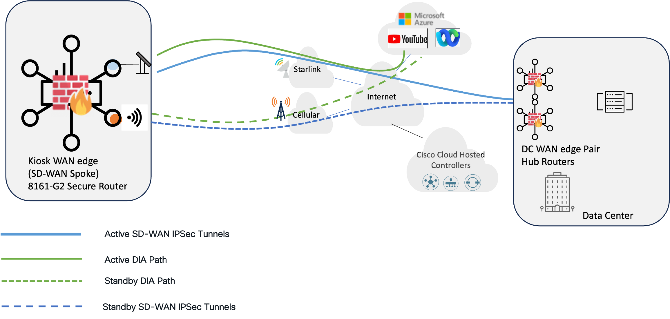
This design scenario addresses the rapid mobilization of business-critical connectivity in temporary retail environments where terrestrial infrastructure is either unavailable or prohibitively expensive to trench for short-term use. The solution leverages a zero-footprint hardware profile to deliver SD-WAN transport resiliency and security across Starlink and Cellular 5G circuits. This ensures that high-volume transactions and inventory data remain protected and persistent, regardless of local infrastructure limitations or the high costs of traditional leased lines.

Application traffic: hybrid cloud and data center dependencies
The retail kiosk application model consists of centralized corporate services and cloud-native SaaS applications. Business-critical "Back-Office" functions, such as real-time inventory reconciliation (ERP), Active Directory authentication, and PCI-compliant payment middleware, are hosted within the corporate Data Center, necessitating a secure, private SD-WAN overlay for data integrity. Conversely, the kiosk leverages public internet paths for "Front-End" retail operations, including SaaS-based Point of Sale (POS) platforms, cloud-managed digital signage updates, and customer loyalty APIs. This hybrid requirement justifies a dual-path strategy: an encrypted overlay for sensitive internal traffic and Direct Internet Access (DIA) path for high-bandwidth, latency-sensitive web services.
Core hardware recommendations
Edge Platform:
The C8161-G2 is selected as the edge platform since its integrated PoE+ support and fanless design eliminate the need for secondary switches or external power injectors in space-constrained or unconditioned environments. The inclusion of a modular 5G/LTE PIM slot enables cellular connectivity, providing high-availability SD-WAN path redundancy. With 1.5Gbps of encrypted throughput and hardware-anchored security, the platform delivers the necessary performance and quantum-safe protection required for modern enterprise micro-sites in a compact form factor
Starlink platform:
The Starlink Mini is designated as the primary LEO (Low Earth Orbit) backhaul solution, specifically engineered for the rapid, "zero-touch" mobilization required in temporary or seasonal environments. Its selection over larger high-performance models is preferred for its all-in-one integrated design, which collapses the antenna and modem into a single IP67-rated chassis. This eliminates the need for separate indoor units (IDUs) and specialized mounting hardware, drastically reducing the physical footprint and deployment complexity for field technicians. Its low power profile (25–40W) allows the site to remain operational on portable battery or solar power systems during early-stage construction or disaster recovery when utility power is unavailable. When paired with the Cisco 8161-G2, the Starlink Mini provides high-speed, low-latency connectivity that functions as a transparent Layer 3 transport for the Cisco SD-WAN overlay
SD-WAN design: Active/backup transport strategy
The design utilizes Starlink as the primary transport, with Cellular 5G configured in backup mode to optimize the balance between high availability and operational expenditure. Since Starlink provides ample capacity for the transactional requirements of a retail kiosk, it serves as the default path for all production and control plane traffic.
By designating the cellular circuit for disaster recovery only, administrators can significantly reduce costs by subscribing to entry-level or "low-data" cellular plans. In this "backup mode," the cellular interface remains dormant until a primary path failure occurs. This eliminates the continuous background consumption of data, such as keepalives and reachability probing that would otherwise exhaust a limited data plan in an "Active/Active" scenario.
SD-WAN tunnel topology: Strict hub-and-spoke
To further preserve satellite and cellular bandwidth, this solution employs a Hub-and-Spoke topology rather than a Full-Mesh architecture. Because retail kiosks only require communication with centralized HQ applications, a Full-Mesh design would create significant protocol redundancy and unnecessary overhead. By restricting the overlay to a Hub-and-Spoke model, the edge device avoids maintaining concurrent tunnels to every other site, thereby eliminating the cumulative bandwidth waste caused by Bidirectional Forwarding Detection (BFD) probing across unused paths. This streamlined approach ensures that maximum throughput is reserved for business-critical transactions rather than the network management "chatter" typically associated with high-density mesh environments.
Device configurations and policy
Enable cellular backup by configuring the last-resort-circuit command in tunnel interface configuration mode. Navigate to Configuration Groups > Transport VPN > Cellular Interface > Tunnel Interface > Last-Resort Circuit (on)
The following configuration is applied to the device:
| sdwan interface cellular0/2/0 tunnel-interface encapsulation ipsec weight 1 color lte last-resort-circuit |
Secure direct internet access
Enable direct internet access over the GigabitEthernet0/0/0 and Cellular0/3/0 interfaces by performing the following tasks:
Table 19. Secure direct Internet access configuration workflow
| Task |
UX2.0 workflow |
||||||
| Enable NAT on the interfaces |
Configuration Groups > Transport VPN > Interface > NAT (on) |
||||||
| Configure NAT DIA Tracker and apply to the WAN Interfaces |
Configuration Groups > Transport VPN > Interface > + Add feature > Tracker > create new Example
|
||||||
| Create a static default route in the service VPN to redirect Internet traffic directly to Starlink |
Configuration Groups > Service VPN > Route > + Add IPv4 Route
|
||||||
| Create security policies on the NGFW to secure the DIA edge |
Refer to the NGFW Configuration Workflow in the following section
|
Tech tip: While a centralized Traffic Policy (formerly referred to as “Data Policy”) can be used to steer specific applications or traffic classes toward that exit using matching criteria, the use of a static default route is recommended for use cases where all Internet traffic is intended to be offloaded.
The following configurations are applied to the device:
| interface GigabitEthernet0/0/1 description Starlink HPUNE00000002047 KITP00228862 ip nat outside endpoint-tracker DIA_Tracker ! interface Cellular0/2/0 description 5G cellular interface ip nat outside endpoint-tracker DIA_Tracker ! endpoint-tracker DIA_Tracker tracker-type interface endpoint-ip 208.67.222.222 ! ip nat inside source list nat-dia-vpn-hop-access-list interface Cellular0/2/0 overload ip nat inside source list nat-dia-vpn-hop-access-list interface GigabitEthernet0/0/1 overload ip nat route vrf 10 0.0.0.0 0.0.0.0 global |
Next Generation Firewall (NGFW) DIA security policies
To secure the Starlink Direct Internet Access (DIA) breakout, this design utilizes the Cisco SD-WAN UX 2.0 Unified Security Workflow. This streamlined interface allows administrators to group complex security functions, such as Layer 7 application visibility and threat prevention, into a single, cohesive policy group.
Tech tip: Security Policy Governance: While this CVD outlines the technical implementation of the Next-Generation Firewall (NGFW), specific firewall rules, threat signatures, and URL whitelists are considered out of scope. Security configurations are highly dependent on organization-specific SecOps mandates and corporate risk-compliance frameworks. The following examples serve as a baseline for retail kiosk hardening.
NGFW configuration workflow
The recommended approach for the retail kiosk is the NGFW Workflow, which automates the mapping of security zones to the transport interfaces.
Table 20. NGFW Configuration Workflow for Direct Internet Access
| Task |
Action (Configuration > Policy Groups > NGFW > Add NGFW Policy) |
| Initialize |
Select "Let’s Do it" and define a unique Policy Name (e.g., DIA_SECURITY). |
| Accept defaults or customize zones |
The UX 2.0 engine will automatically suggest Source Zones (e.g., LAN_VPN) and Destination Zones (e.g., Internet_DIA) based on the naming of the interfaces in the Configuration group service and transport profiles |
| Define rule sets |
Define Rule Sets by specifying traffic sources, destinations, and the "Inspect" action to trigger the Unified Threat Management (UTM) engine |
| Advanced Inspection |
Within the "Additional Settings" pane, create an Advanced Inspection Profile to activate deep-packet analysis. |
Example: kiosk-specific NGFW policy
This security policy focuses on high-efficiency inspection that secures the perimeter without the high CPU overhead or latency associated with heavy cryptographic decryption.
Table 21. Example Cisco NGFW DIA security policy for retail kiosk with Starlink
| Security feature |
Recommendation |
Justification for retail kiosk |
| Layer 7 Firewall |
Application Aware Inspection |
Provides stateful L3-L7 protection. Ensuring that only authorized traffic (POS, HTTPS, etc.) are allowed to access the Internet via DIA. |
| URL Filtering |
Category-Based Blocking |
Blocks non-business categories (Gaming, P2P, High-BW Video) to ensure Starlink capacity is reserved for critical transactions and inventory updates |
| Intrusion Prevention (IPS) |
Connectivity over Security |
Employs a balanced signature set to detect known exploits. This offers optimized security to performance ratio. |
Hub-and-spoke SD-WAN topology
In Cisco Catalyst SD-WAN Manager UX 2.0, the workflow has been streamlined to move away from the classic policy builders.
1. Navigate to Configuration > Topology
2. Select Add Topology
3. Choose the Hub-and-Spoke template.
4. Define Hub Sites and Spoke Sites using pre-configured Site Groups.
Once the roles are assigned, the manager automatically generates the centralized control policy required to regulate TLOC advertisements. This ensures that spoke-to-spoke traffic is forced through the hub by restricting direct TLOC reachability between branch nodes. This centralizes the control plane logic without requiring a manual build out of individual sequences in the classic policy engine.
Table 22. SD-WAN topology workflow (hub and spoke)
| Configuration Task |
Action (Configuration > Topology) |
| Create Topology |
Click Add Topology and select the Hub-and-Spoke model. |
| Name and describe |
Provide a unique name for the policy (e.g., DC_Hub_Spoke). |
| Add Hubs |
Select the Site Groups that represent the Data Center or Regional Hubs. |
| Add Spokes |
Select the Site Groups for branch offices or remote nodes. |
| Advanced Settings |
(Optional) Toggle Spoke-to-Spoke Connectivity if a partial mesh or specific exceptions are required. |
| Preview and Save |
Review the graphical representation of the traffic flow before clicking Save to push to the SD-WANs. |
Mobile example: electric utility fleet vehicles
This design scenario addresses the requirements of fleet vehicles such as high-voltage bucket trucks and mobile command centers that require persistent SD-WAN fabric membership while in motion or parked at job sites. In these environments, the vehicle serves as a mobile field office, supporting a suite of critical applications including real-time Outage Management (OMS), GIS-based asset mapping, and AI-driven Video Telematics. By leveraging a multi-transport SD-WAN architecture, these vehicles maintain the high-bandwidth, low-latency connectivity required to sync work orders, stream live infrastructure inspections to remote engineers, and ensure crew safety during emergency grid restoration.
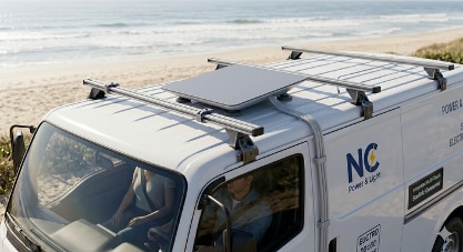
Core hardware recommendations
For vehicle fleet deployments, the Cisco Catalyst IR1835 Industrial Router is deployed at the edge, delivering ruggedized physical construction and integrated mobility features This ruggedized platform is purpose-built to withstand the constant vibration, shock, and extreme temperature fluctuations inherent in vehicle mounting. For mobile applications, the Starlink Performance (Gen 3) terminal is deployed in conjunction with a Mobile Priority service plan instead of the Starlink Mini. This combination delivers the wider aperture, enhanced tracking capabilities, and official in-motion certification required to maintain stable fabric connectivity at highway speeds.
To complement satellite transport, a Cisco PIM-5G-B (Sub-6 GHz) is recommended for the cellular interface. This module provides 5G connectivity with 4G LTE fallback, ensuring high-speed, low-latency performance in urban areas while maintaining reachability in rural fringe zones. To maximize underlay path resiliency, the PIMs can be outfitted with dual SIM cards from diverse carriers, providing a secondary layer of cellular-level redundancy directly beneath the primary SD-WAN transport failover logic.
SD-WAN design: Active/active mobility strategy
The transport strategy for fleet vehicles shifts from a standard Active/Backup model to an Active/Active approach to proactively mitigate the two primary risks of mobile connectivity: Starlink obstructions and cellular dead zones. By maintaining tunnels over both LEO satellite and 5G/LTE paths, the SD-WAN fabric can perform dynamic traffic rerouting when in-motion vehicles encounter satellite signal "shading" from tree canopies and overpasses, or when they outpace cellular coverage maps in remote sectors.
By maintaining concurrent tunnels over both Starlink and 5G/LTE, the SD-WAN fabric can perform load sharing with Application-Aware routing (AAR). If the Starlink dish is momentarily obstructed, critical traffic is shifted to cellular without dropping the session. Conversely, if cellular signal fades in a remote valley, Starlink provides the necessary high bandwidth backhaul to maintain enterprise connectivity.
Internet access for fleet vehicles is strictly limited to mission-critical applications and governed by a "Zero Trust" perimeter. To comply with stringent NERC CIP and utility-sector cybersecurity mandates, this design explicitly prohibits Direct Internet Access (DIA) from the vehicle level. Instead, all traffic, regardless of whether it originates over Starlink or Cellular, is encapsulated within the SD-WAN fabric and backhauled to a centralized Regional Hub or Data Center.
This “backhauled Internet” security model ensures that:
● Centralized Inspection: All web-bound traffic must egress through a hardened security stack within a corporate DMZ, where it undergoes Deep Packet Inspection (DPI), Firewalling, and Intrusion Prevention (IPS).
● Application Whitelisting: Only specific, pre-authorized domains required for OMS, GIS, and Telematics are reachable. All other "commodity" internet traffic is dropped at the source.
● Uniform Policy Enforcement: By routing traffic back to a central gateway, the utility maintains a single, auditable point of control, ensuring that a bucket truck in a remote valley is subject to the same rigorous security posture as a workstation in the corporate headquarters.
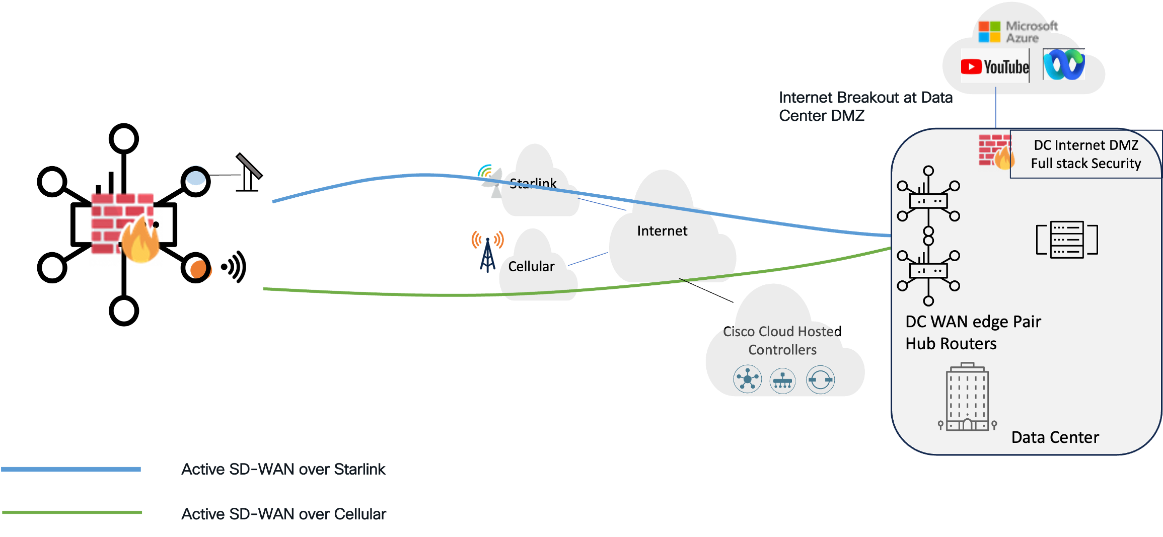
SD-WAN configurations and policies
Enable active/active routing across both SD-WAN tunnels/transports by performing the following tasks
| Task |
Workflow |
| Ensure last-resort-circuit is disabled (default setting) on each transport tunnel to ensure tunnels and DIA paths are active |
Configuration Groups > Transport VPN > Interface > Tunnel Interface > Last-Resort Circuit (off) |
| Adjust the Administrative Distance (AD) of the Starlink-learned DHCP default route to 254. This achieves AD parity with the cellular default route (which cannot be adjusted through configuration), allowing both transports to serve as candidates for SD-WAN tunnels and DIA transports. |
Configuration Groups > Transport VPN > Ethernet Interface > IPv4 Settings > Dynamic DHCP Distance > (Global) 254.
|
The following configuration is applied to the device:
| interface GigabitEthernet0/0/1 description Starlink HPUNE00000002047 KITP00228862 ip address dhcp client-id GigabitEthernet0/0/1 ip dhcp client default-router distance 254 |
SD-WAN Application-Aware Routing (AAR) policy
To mitigate the intermittent "brownouts" inherent in Starlink and Cellular transports, this design utilizes an Application-Aware Routing (AAR) policy. This policy enables active load-sharing across both wireless paths, proactively steering traffic away from any link that exceeds established latency or packet loss SLA thresholds. Enhanced AAR (EAAR) is recommended to optimize impairment detection on these bandwidth-constrained circuits. Unlike traditional AAR, which can consume significant overhead through aggressive BFD timers, EAAR leverages passive application metadata to detect path degradation in near real-time based on actual traffic flows. This provides rapid failover capabilities while preserving maximum bandwidth for mission-critical applications.
Tech tip: Note: EAAR is enabled via the system-level configuration, as detailed in the Baseline Configuration section above.
AAR policy implementation workflow
To build a resilient AAR policy for the electric utility fleet, applications are categorized based on their sensitivity to the fluctuating performance of Starlink and Cellular transports. This hierarchy ensures that mission-critical traffic (OMS) is pinned to the most stable path, while data-intensive workflows (GIS) leverage the maximum available bandwidth.
Step 1. Define Groups of Interest (Lists)
Before building the policy logic, identify the applications and sites involved in the mobile fabric.
Application Lists:
● UTILITY_CRITICAL: Includes OMS and SCADA (DNP3/IP) custom applications.
● FIELD_OPERATIONS: Includes GIS (ArcGIS), Work Order Management, and Collaboration
● FLEET_TELEMETRY: Includes AI Dash Cams and Vehicle Diagnostics.
● VPN List: Define the Service VPN (e.g., VPN 10) where these applications reside.
Tech tip: Custom applications are defined in the SD-WAN configuration catalog. Refer to the Policy Groups Configuration Guide, Cisco IOS XE Catalyst SD-WAN Release 17.x for information
Step 2. Establish SLA Classes (Performance Thresholds)
Define the "Success Criteria" for each traffic tier. Unlike standard AAR, EAAR will use these thresholds in conjunction with passive metadata to detect brownouts.
| SLA class |
Max latency |
Max loss |
Intent |
| CRITICAL_SLA |
200 ms |
1 % |
Prioritize stability for grid commands. |
| STANDARD_SLA |
400 ms |
3 % |
Balanced performance for field productivity |
| BULK_SLA |
600 ms |
5 % |
Maximize throughput for telemetry. |
Step 3. Create the EAAR Traffic Policy Profile (UX2.0)
Using the Cisco Catalyst SD-WAN Manager UX2.0 workflow, construct the sequences that define path preference.
| Sequence |
Application list |
Preferred path |
Rationale |
| 10 |
UTILITY_CRITICAL |
Cellular |
Cellular typically provides a more deterministic path for low-bandwidth, high-priority grid telemetry. |
| 20 |
FIELD_OPERATIONS |
Load Share |
High-resolution GIS map tiles benefit from the aggregated capacity of both links. |
| 30 |
FLEET_TELEMETRY |
Starlink |
Offloads high-volume video data to the satellite link to preserve cellular data. |
Step 4. Policy Association and Deployment
Associate the completed Traffic Policy Profile with the Fleet Policy Group. Deploy the policy to the SD-WAN controllers, which will then orchestrate the path selection logic across the mobile fleet.
Cloud-connected remote branch
This profile is engineered for distributed enterprises that require the "always-on" reliability of a traditional branch, optimized for high-autonomy environments. This design prioritizes maximum uptime and simplified remote management, ensuring that mission-critical services remain online without the need for on-site technical intervention.
● Integrated Rural Travel Center: A multi-functional retail environment supporting mission-critical Point-of-Sale (POS) transactions, real-time fuel tank monitoring, and Quick Service Restaurant (QSR) operations.
● Rural Satellite Medical Clinic: A community health outpost in remote territory relying on high-resolution telehealth consultations, real-time Electronic Health Record (EHR) access, and secure medical imaging synchronization.
● Rural Bank Branch (Small Footprint): A limited-service financial office in a rural township requiring resilient connectivity for ATM operations and encrypted access to centralized banking applications.
Integrated rural travel center
The design must support three distinct business operations: Fuel, Retail, and Quick Service Restaurant (QSR), all under one roof. This requires a resilient SD-WAN architecture that uses dual transports concurrently, ensuring that critical financial and operational traffic remains uninterrupted even if a primary link degrades or completely fails.
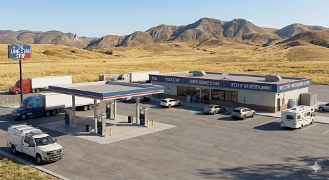
The strategy balances performance and capacity by combining two distinct transport types:
● Terrestrial (DSL/Cable): A deterministic transport (100 Mbps Down / 20 Mbps Up) providing predictable latency and stable jitter. This is the preferred path for sensitive financial transactions, POS, and fuel controller monitoring.
● LEO Satellite (Starlink): A high-capacity transport (100–250 Mbps Down / 10–20 Mbps Up) serving as the exclusive DIA (Direct Internet Access) path. Guest Wi-Fi and cloud-monitored video surveillance traffic are pinned to this transport to leverage its high-throughput capabilities without consuming private fabric bandwidth.
Core hardware recommendations
For this deployment, the Cisco 8231-G2 Secure Router is utilized as the WAN Edge. This platform is selected for its high SD-WAN (IPsec) throughput, full feature NGFW and integrated PoE+ support, which allows the router to directly power internal access points and IoT sensors without requiring additional switching hardware.
To provide the high-capacity secondary path, the Starlink Performance (Gen 3) kit is utilized. Its enhanced GPS sensitivity and 140° Field of View ensure stable link connectivity during orbital handoffs, which is critical for preventing the jitter-induced timeouts that often plague satellite-based POS systems.
SD-WAN Design: Active/active hybrid strategy
The transport strategy for the Lean Branch utilizes an Active/Active Hybrid approach that optimizes the distinct strengths of terrestrial and satellite links. By maintaining concurrent tunnels over the terrestrial (DSL/Cable) path and the Starlink LEO path, the SD-WAN fabric performs dynamic Application-Aware Routing (AAR) based on real-time tunnel health. Mission-critical, latency-sensitive traffic, such as POS authorizations, VoIP, and fuel telemetry, is pinned to the Terrestrial path to leverage its predictable jitter and stable latency. Conversely, data-intensive bulk traffic, including inventory syncs and back-office administration, is directed to the Starlink path to prevent saturating the critical terrestrial circuit.
Secure Direct Internet Access (DIA) over Starlink LEO
Internet access for the Lean Branch is governed by a split-security model that balances corporate protection with the guest experience. To preserve private fabric bandwidth and ensure PCI-DSS compliance, high-volume, untrusted traffic (such as Guest Wi-Fi and Cloud Video Surveillance) is offloaded via Direct Internet Access (DIA) exclusively through the Starlink terminal. This traffic is prohibited from entering the SD-WAN overlay, preventing guest browsing from competing with critical financial data. Security is enforced via the Catalyst 8231-G2’s integrated L7 Firewall and URL Filtering engine, which scrubs all DIA traffic against corporate policies. Furthermore, the architecture utilizes distinct service VPNs (VRFs) to logically airgap the POS Segment from Forecourt Fuel and Guest segments, preventing lateral movement within the branch network.
Performance Optimization (App-QoE) Design: TCP Optimization and Forward Error Correction (FEC)
To achieve "Enterprise-Grade" performance over "Best-Effort" satellite transport, the 8231-G2 secure router supports targeted App-QoE features. TCP Optimization acts as a transparent proxy for Starlink-bound flows, acknowledging packets locally to mitigate the satellite-induced "slow-start" effect. To combat weather fade or orbital handoff drops, Forward Error Correction (FEC) inserts redundant parity packets, maintaining stable POS heartbeats and VoIP sessions during momentary link degradation. For the most critical traffic, such as Forecourt fuel system telemetry or financial transactions, the architecture employs Packet Duplication; this simultaneously transmits identical packets across both terrestrial and Starlink paths, ensuring a hitless experience even if one transport fails entirely.
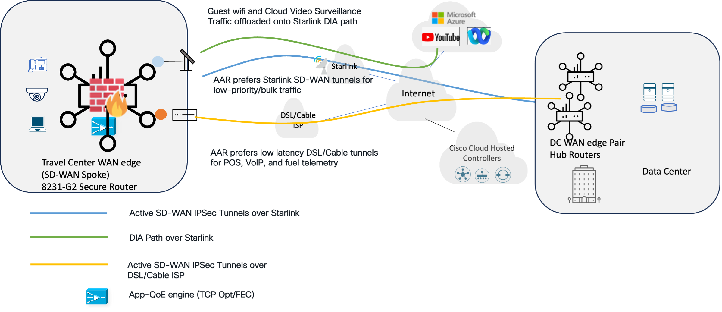
SD-WAN router configuration
The configurations for this profile follow the Active/Active forwarding model established in the previous case study, with one specific adjustment to the transport interface logic. In the mobile deployment, the use of Starlink and Cellular required a DHCP Distance of 254 to align with cellular default routing. However, the Lean Branch replaces cellular with a Terrestrial (DSL/Cable) link. Since both Starlink and the Terrestrial ISP provide standard DHCP handoffs, the administrative distance for both transports is reverted to "1".
| Configuration task |
Workflow |
| Ensure last-resort-circuit is disabled (default setting) on each transport tunnel to ensure tunnels and DIA paths are active |
Configuration Groups > Transport VPN > Interface > Tunnel Interface > Last-Resort Circuit (off) |
| Adjust the Administrative Distance (AD) of the Starlink and terrestrial ISP learned DHCP default routes to 1. |
Configuration Groups > Transport VPN > Ethernet Interface > IPv4 Settings > Dynamic DHCP Distance > (Global) 1. |
SD-WAN policies
Application-Aware Routing (AAR): The logic for the AAR policy is implemented using the same foundational process as the mobile SD-WAN case study, and the detailed configuration workflow will not be repeated here. However, the specific SLA thresholds and application groupings have been customized for the rural travel center environment. Unlike the mobile deployment, which prioritized high-bandwidth telemetry, this policy focuses on the distinct performance requirements of Point-of-Sale (POS) transactions and Fuel-Tank SCADA systems. These mission-critical flows are governed by stricter latency and jitter tolerances to ensure stability over the Terrestrial "anchor" path, while broader "Best-Effort" SLAs are applied to the Starlink path for back-office administration and inventory management.
Direct Internet Access (DIA): The design provisions internet exit exclusively for the Guest Wi-Fi (QSR/Restaurant) and Cloud-Monitored Video VPNs by pinning these services to the Starlink path via default routing. To preserve the limited bandwidth of the Terrestrial "anchor" circuit for protected POS and operational data, the resiliency logic dictates that this non-mission-critical guest and video traffic will not failover to the DSL/Cable link in the event of a Starlink outage.
Application Quality of Experience (App-QoE): This case study introduces App-QoE features, a critical addition for branches utilizing LEO satellite backhaul. App-QoE provides a suite of tool, including TCP Optimization, Forward Error Correction (FEC), and Packet Duplication, designed to accelerate application performance and mitigate the higher latency and packet loss of the Starlink path. The next section provides a deep dive into the App-QoE architectural design, provisioning workflow, and policy enforcement.
App-QoE architecture and validation
The Catalyst SD-WAN App-QoE architecture decouples traffic intelligence from data processing by utilizing a dual-role system consisting of Service Controllers (SC) and External Service Nodes (ESN). The SC acts as the "forwarder," inspecting data flows against centralized policies to identify and forward traffic requiring optimization, while the SN serves as the "optimization engine" that performs the resource-intensive heavy lifting before returning the processed traffic to the Service Controller/Hub for transmission.
Branch App-QoE architecture: Integrated Service Node (ISN)
For the rural travel center, the 8231-E-G2 SD-WAN secure router as an Integrated Service Node (ISN), consolidating both the SC and SN functions. In this model, the router utilizes a dedicated internal service container within the IOS-XE software to process optimizations like TCP Proxy. Traffic is redirected internally from the data plane to this container and back, providing a high-performance "all-in-one" footprint without the need for extra hardware.
Hub App-QoE architecture: Service controllers and external nodes
At the Data Center/Hub site, the architecture shifts to a distributed model to manage high-scale branch aggregation. The hub routers function as Service Controllers, serving as the intelligent policy enforcement points that identify flows requiring optimization. Rather than processing these flows locally, the controllers redirect them to a single instance or cluster of External Service Nodes (ESNs). These dedicated appliances act as high-performance engines for TCP Optimization, Data Redundancy Elimination (DRE) and LZ compression, processing the traffic before returning it to the hub router for final delivery. This separation of duties allows the hub to scale horizontally by adding more ESNs as branch count increases, ensuring that heavy computational tasks never bottleneck the routing data plane. For this rural travel center deployment, Cisco 8500-G2 Series routers serve as the Hub/Service Controllers, while Catalyst 8000V instances function as the External Service Nodes.
The following diagram illustrates the App-QoE architecture at the branch and hub locations.
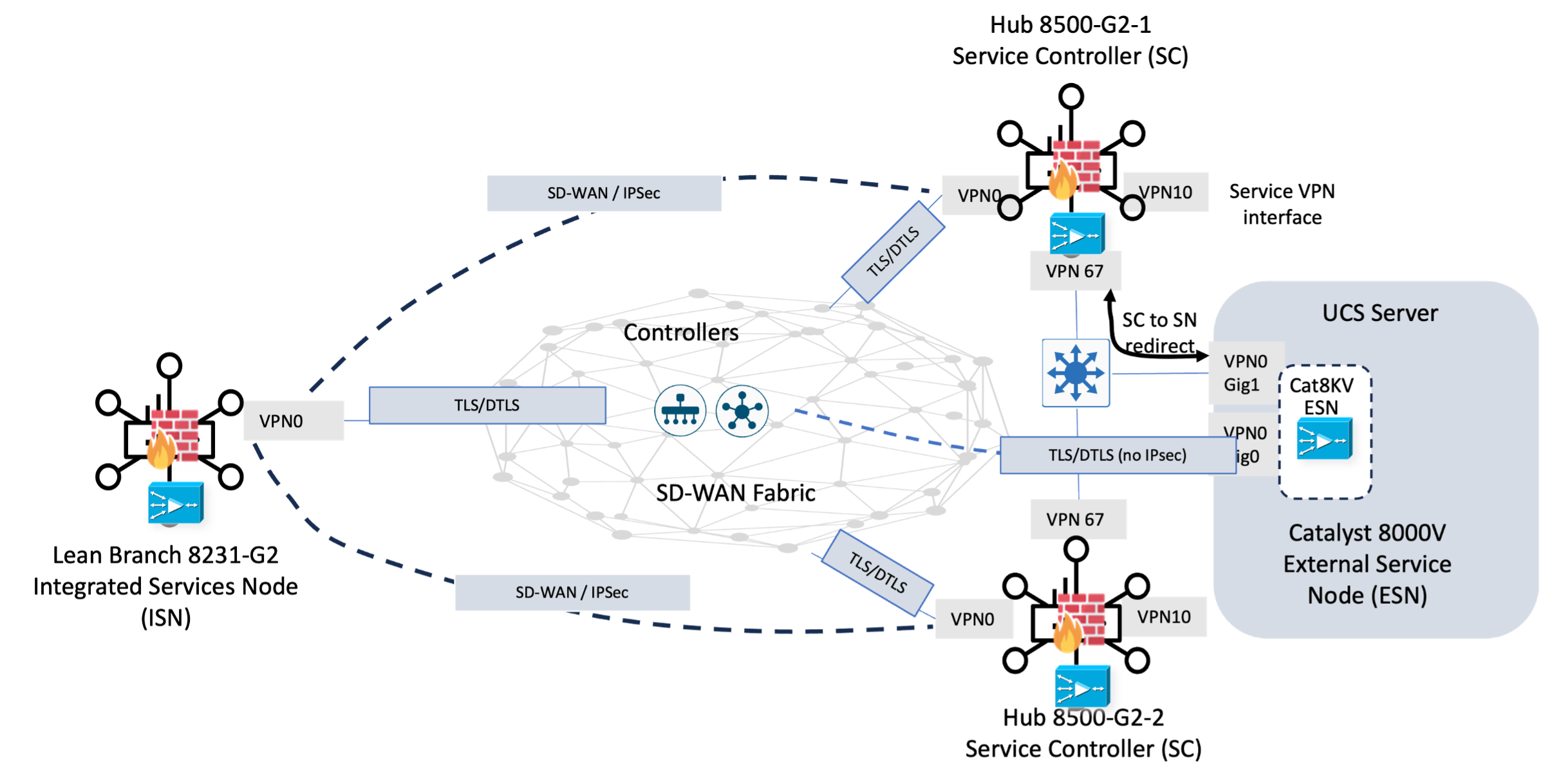
App-QoE implementation workflow
The deployment of App-QoE for the travel centers follows a three-phase workflow designed to mitigate transport volatility across LEO and terrestrial links.
Table 23. App-QoE configuration and policy workflow
| App-QoE deployment phase |
Focus |
Key actions |
| 1: Resource Provisioning |
Resource Activation |
Enabling the ISN container on the 8231-E-G2 |
| 2: Policy |
Traffic Policy Definition |
Applying app-qoe traffic policy actions to critical traffic |
| 3: Verification |
Observability |
Utilizing the 20.18 Optimization Dashboard to confirm bandwidth savings and link health. |
Phase 1: resource provisioning
Branch: Integrated Service Node (ISN) activation
For the 8231-E-G2, the activation is handled entirely through the Catalyst Manager UX2.0 Configuration Groups, removing the need for manual CLI resource carving.
Table 24. App-QoE branch ISN configuration workflow
| Task |
UX2.0 configuration group workflow |
| Activate Branch App-QoE Integrated Services Node |
Configuration > Configuration Groups > select configuration group designated for the lean branch |
| Edit the service profile and click on “+ add new feature” |
|
| Select App QoE Feature Profile and “add new” |
|
| Input Name, description, and check the Service Node and Forwarder boxes next to Device AppQoE Role |
This configuration workflow translates to the Catalyst Manager interface as shown below:
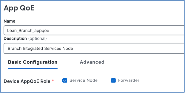
Once provisioned, Catalyst Manager translates this configuration into the corresponding CLI structure on the branch device. Below is the branch ISN App QoE CLI configuration:
| service-insertion appnav-controller-group appqoe ACG-APPQOE appnav-controller 192.168.2.1 ! service-insertion service-node-group appqoe SNG-APPQOE service-node 192.168.2.2 ! service-insertion service-context appqoe/1 cluster-type integrated-service-node appnav-controller-group ACG-APPQOE service-node-group SNG-APPQOE enable vrf global |
Data Center: Service controller and External Service Node (ESN) activation
In the Data Center, the provisioning workflow follows a distributed model across the 8500-G2 (SC) and Catalyst 8000V (ESN) instances. This separation allows the Hub to handle high-scale branch aggregation by offloading heavy optimization tasks to dedicated service nodes.
Prerequisites: Distributed resource mapping
In the Data Center, the 8500-G2 (SC) and the Catalyst 8000V (ESN) are managed through distinct Configuration Groups tailored to their specific hardware roles. To enable App-QoE, these devices are logically linked via a shared Service Controller Group definition within the UX 2.0 interface. This grouping allows the 8500-G2 to track the health of the 8000V cluster and provides the necessary redirection path for offloading resource-intensive tasks, such as TCP Proxy and DRE, away from the primary hub routing plane. Before deployment, ensure the 8000V instances are correctly licensed for App-QoE to support high-scale branch aggregation without bottlenecking the data plane.
Hub App-QoE Service Controller (SC) configuration workflow
Table 25. App-QoE Hub SC configuration workflow
| Task |
UX2.0 configuration group workflow |
| Activate Hub App-QoE Service Controller (SC)
|
Configuration > Configuration Groups > select configuration group designated for the Data Center Hub routers |
| Edit the service profile and click on “+ add new feature” |
|
| Select App QoE Feature Profile and “add new” |
|
| Input Name, description, and check the Forwarder box next to Device AppQoE Role |
|
| Create the SC forwarder IP address device specific variable |
Modify the “Forwarder IP address” field to a device specific variable such as {{SC_forward_IP_address}} so that it can be input later each hub router during provisioning. This is the IP address assigned to interface in the unique VPN (67) on each Service controller used to send traffic to the Service Node for optimization |
| Select the VPN name associated with the forwarder IP address |
Select the VPN name associated with the Forwarder Interface from the dropdown window |
| Add Service Node Group |
Click + add service node group and provide a name (or accept default) |
| Add Service Nodes |
Input the IP address(es) of the External Services Node(s) as global variables or define as device specific variables to be assigned during provisioning This is the IP address on the External Service Node which corresponds to the Redirect IP address. |
This configuration workflow translates to the Catalyst Manager interface as shown below:

Select Add Services Node Group and add the IP Address of the External Service Node(s).
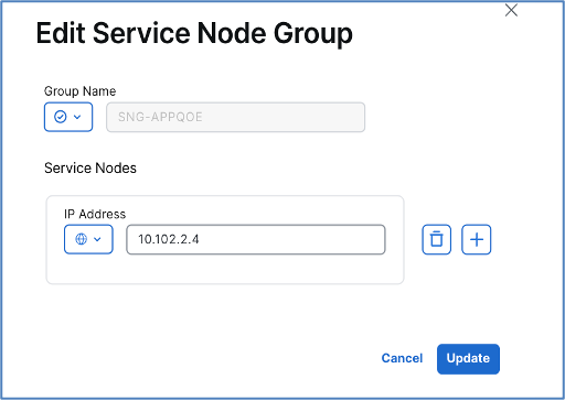
Once provisioned, Catalyst Manager translates this configuration into the corresponding CLI structure on the hub devices. Review the Hub Service Controller (SC) App QoE CLI configuration below:
| ! CLI rendering of the Service Controller configuration on the Hub Routers
service-insertion appnav-controller-group appqoe ACG-APPQOE appnav-controller 10.102.2.2 vrf 3 ! service-insertion service-node-group appqoe SNG-APPQOE service-node 10.102.2.4 ! service-insertion service-context appqoe/1 cluster-type service-controller appnav-controller-group ACG-APPQOE service-node-group SNG-APPQOE enable vrf global |
Hub External Service Node (ESN) configuration:
The Catalyst 8000V instances are provisioned as high-performance engines by toggling the Service Node switch to Enabled within their respective App-QoE Feature Profiles. Once enabled, the 8000V must be associated with the Service Controller Group defined on the 8500-G2. This association automates the heartbeat connection and the Service Interface mapping, allowing the 8000V to receive redirected traffic, perform deep-packet optimization, and return the processed data to the hub for final WAN transmission.
| Task |
UX2.0 configuration group workflow |
| Activate Hub AppQoE Service Node (SN)
|
Configuration > Configuration Groups > select configuration group designated for the Data Center Service Node(s) (8000V) r |
| Edit the service profile and click on “+ add new feature” |
|
| Select App QoE Feature Profile and “add new” |
|
| Input Name, description, and check the Service Node box next to Device AppQoE Role |
This configuration workflow translates to the Catalyst Manager interface as shown below:
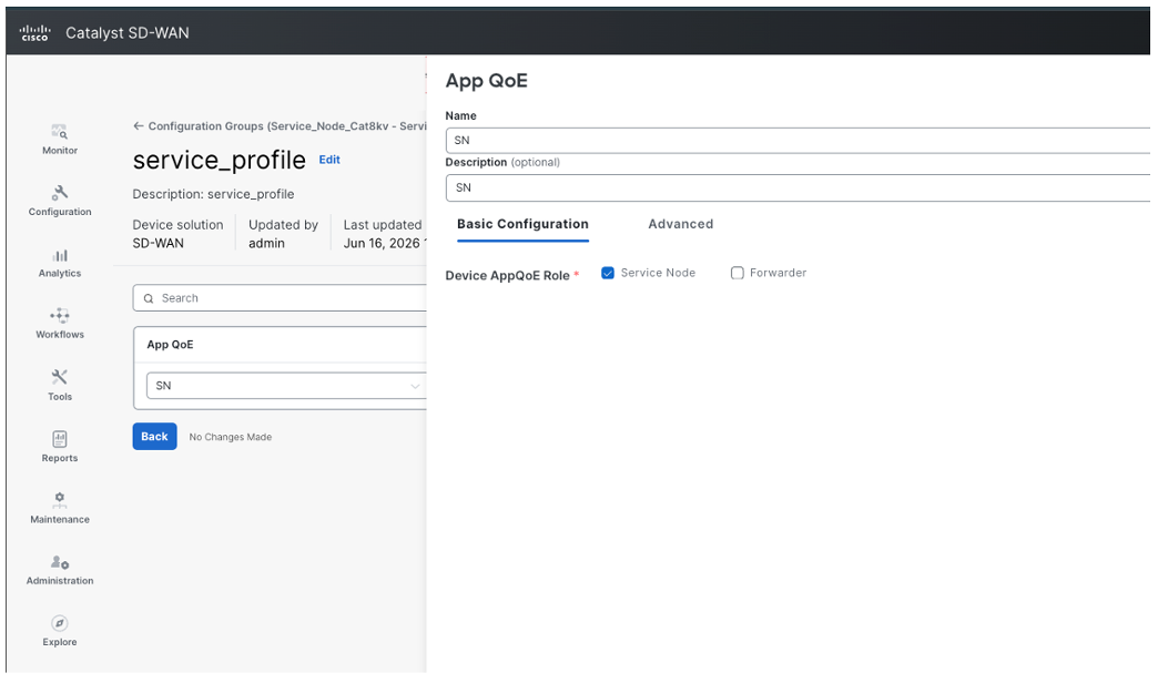
Note: The Service Node will not have any Service VPN Parcel, as it does not connect to the branch LAN. The Transport and Management Profile include Management Parcel and two Transport VPN Connections, one for control connections which needs to have Tunnel Definition and one for Redirect Connection without Tunnel Definition.
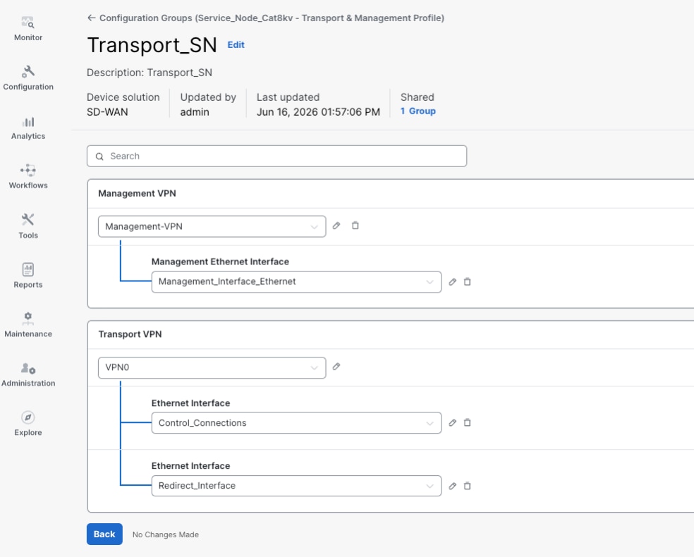
As of version 20.18, a few specific Service Node parameters are not yet natively exposed in the App-QoE UI. To complete the deployment and ensure the router is properly tuned for L4-L7 processing, a CLI Add-On Template must be leveraged to push the following configuration:
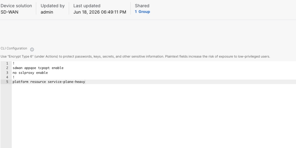
Once provisioned, Catalyst Manager translates this configuration into the corresponding CLI structure on the service node. Review the External Service Controller (ESN) App QoE CLI configuration below:
| service-insertion service-node-group appqoe SNG-APPQOE device-role service-node service-node 192.168.2.2 |
Phase 2: centralized traffic policy configuration
Enable app-qoe feature optimization by matching applications and selecting the optimization feature(s) in the centralized traffic policy based on application criticality:
● TCP Optimization & Adaptive FEC: Enabled for Corporate and POS VPNs to mitigate satellite latency and protect against transient loss. FEC remains Adaptive, inserting parity packets only when link quality degrades below defined thresholds to preserve bandwidth.
● Packet Duplication: Reserved for ultra-critical Financial Payments (e.g., Visa, Mastercard). This replicates egress packets across both Terrestrial and Starlink paths simultaneously to ensure hitless failover
To streamline the Phase 2 workflow, the policy configuration is broken down into four modular steps within the UX 2.0 interface:
Table 26. App-QoE centralized traffic policy configuration workflow
| Task |
Workflow |
| Define Policy Lists |
Configuration > Policy Groups and select the objects and profiles tab on the right. |
| Create VPN lists (e.g. POS_VPN, CORP_VPN) to identify service VPNs subject to optimization |
|
| Create Application Lists (ego Office365) to identify traffic subject to optimization |
|
| Create Traffic Rules |
Configuration > Policies > Application Priority & SLA Policy. Select existing policy and add new sequences for applications that require optimization |
| Traffic rule example for TCP Optimization
|
Match: Application List TCP_APPS Action: AppQoE Optimization Service Node Group SNG-APPQOE, check TCP Optimization |
| Traffic rule example for FEC Adaptive
|
Match: Application List VIDEO_APPS Action: Loss Correction Type: FEC Adaptive |
| Traffic Rule Example for Packet_Duplication:
|
Match: Application List POS_Transactions Action: Loss Correction Type: Packet Duplication |
| Associate and deploy |
Save the policy and associate it with the appropriate Site Lists. Upon deployment, the Manager pushes the configuration to the Service Controllers to initiate the redirection and optimization process. |
| Define Policy Lists |
Configuration > Policy Groups and select the objects and profiles tab on the right. |
Phase 3: verification
The Cisco Catalyst SD-WAN 20.18 release introduces significant observability enhancements, shifting the verification process from manual CLI checks to a centralized, visual experience. Phase 3 now focuses on leveraging the Optimization and App Flow dashboards to validate that the Starlink and Terrestrial paths are performing as designed.
GUI validation in 20.18
The 20.18 release introduces the Optimization Dashboard (Analytics > Optimization), providing a consolidated, "at-a-glance" view of App-QoE health across the entire fabric. This interface allows administrators to verify feature enablement, such as TCP Optimization, FEC, and Packet Duplication, while visualizing bandwidth efficiency and throughput gains achieved by mitigating satellite latency. Through the App Flow Heat Map, users can perform deep-dive "Application 360" verifications for mission-critical traffic, enabling real-time monitoring of SLA violations. In the event of a Starlink signal fade, the dashboard provides visual confirmation that Adaptive FEC or Packet Duplication successfully maintained the application's QoE score, ensuring operational continuity.
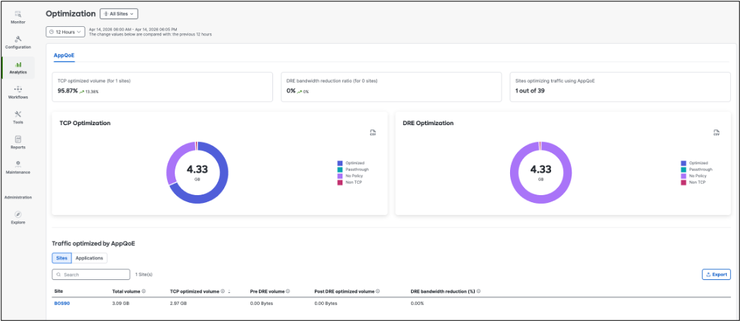
Command-line interface verification
While the GUI is the primary tool for the CVD, the CLI remains essential for real-time troubleshooting at the edge.
Branch (8231-E-G2):
● show sdwan appqoe flow all: Verify the number of optimized vs. bypass flows. Look for the Retransmission Reduction count to see the direct impact of TCP Optimization on the LEO link.
● show sdwan appqoe status: Confirms the Integrated Service container is "Green" and the VPG is up.
At the Hub (8500-G2):
● show service-insertion type appqoe appnav-controller-group: Confirm the Service Controller is successfully heart-beating with the 8000V Service Nodes.
● show sdwan appqoe flow active: Verify that the redirected flows from the remote branches are hitting the ESN cluster for processing.
At the SN (Catalyst 8000V):
· show service-insertion type appqoe service-node-group: Confirms the configuration details of service node using IPv4 address in a service node group.
· show service-insertion type appqoe statistics service-node-group: Confirms the traffic statistics for service node using IPv4 address in a service node group.
Performance testing the impact of TCP optimization on LEO transport
To validate the performance gains of the Cisco SD-WAN Optimization stack over Starlink satellite links, a series of sustained throughput tests were conducted between two remote fabric sites utilizing iPerf3. Widely recognized as the networking industry standard for benchmarking sustained data-plane throughput, iPerf3 was deployed natively on Ubuntu LTS endpoints positioned behind the WAN Edge routers to accurately measure raw TCP stream behavior.
The testing baseline utilized a standard LEO underlay with a typical round-trip time (RTT) of 30–50ms paired with an inherent satellite packet loss baseline of 1–2%. The benchmarks directly compared unoptimized standard TCP flows against those leveraging the IOS-XE TCP Optimization stack to demonstrate how the fabric overcomes the effects of even minor packet drop rates on a satellite path.
Test Methodology: A single-stream, sustained TCP flow was initiated via iPerf3 between clients connected over an SD-WAN tunnel to measure performance.
Empirical Performance Summary: Standard vs. TCP-Optimized LEO Fabric: The results of the sustained iperf3 benchmarking iterations demonstrate a massive performance delta when enabling the Cisco IOS-XE TCP Optimization stack over the Starlink underlay. By mitigating the throughput-crushing effects of the baseline 1–2% satellite packet loss and 30–50ms latency, the optimization engine effectively unlocked the true capacity of the LEO transport.
| Traffic direction |
Baseline (unoptimized) |
TCP optimized |
Throughput improvement |
| Sustained download |
55 Mbps |
206 Mbps |
274% |
| Sustained upload |
11 Mbps |
20 Mbps |
81% |
Mission-critical branch resiliency
This profile is engineered for high-stakes enterprise environments that demand "zero-fail" reliability and sophisticated traffic orchestration. These sites operate as critical regional hubs, requiring high-bandwidth, low-latency connectivity to support dense user populations and real-time synchronized applications.
Examples:
● Regional Investment Hub: A mid-sized financial office hosting private wealth advisors and market analysts. These sites require "five-nines" availability to support high-def video conferencing, real-time market data feeds, and persistent virtual desktop infrastructure (VDI) sessions for mobile staff.
● National Retail Bank (Hub Branch): A high-volume consumer banking center that serves as a regional anchor. These facilities must maintain 100% uptime for a dense network of ATMs, instant credit card issuance systems, and secure synchronization between local edge servers and the centralized core banking database.
● Small Campus: A corporate outpost or research facility that functions as an extension of the main headquarters. These sites prioritize seamless integration with HQ resources, utilizing deep packet inspection (DPI) to ensure that mission-critical SaaS and ERP traffic are steered over the most stable path.
Resilient banking hub
In the modern financial landscape, regional hubs have evolved into Resilient Banking Hubs, high-density environments where consumer banking, private wealth, and corporate lending intersect. As essential drivers of the national economy, these sites require a "never-down" architecture. For a national bank, a single fiber-optic cable cut is not just a technical glitch; it is a direct threat to institutional trust and stability.
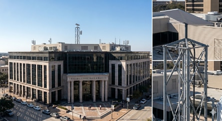
High-availability requirements
To meet this mandate, the hub network must move beyond simple backup links to a fabric that is mathematically resilient, physically diverse, and cryptographically future proof. This design addresses three high-priority traffic profiles:
● The "Gold Zone" Core: Synchronous banking transactions and private wealth data requiring sub-second failover and zero packet loss.
● Real-Time Market Data: High-performance investment suites utilizing Multicast Overlay Routing for wire-speed trading feeds.
● Cloud-Native Operations: Heavy reliance on SaaS (M365, Salesforce) and Cisco Secure Access (SSE) that requires App-QoE (TCP Optimization and DRE/LZ) to maintain performance over long-haul paths.
Engineering for total path diversity
True resiliency is only achieved when the "last mile" is physically decoupled to eliminate common-mode failures, such as a single backhoe taking out shared underground conduits. By integrating Starlink LEO Satellite transport alongside traditional terrestrial fiber, the hardware stack is designed as an Active/Active N+1 redundancy pair. This ensures the network remains operational even if a router, a fiber line, or a local terrestrial provider fails entirely.
Core hardware recommendations
Cisco Edge Platform: Cisco 8355-G2 Secure Routers
The Cisco 8355-G2 Secure Router provides the hardware foundation for this design, deployed in a High-Availability (HA) cluster to maintain session persistence. The platform utilizes a dedicated Secure Networking Processor to execute Post-Quantum Cryptography (PQC) at line-rate, protecting data against future decryption threats using ML-KEM algorithm. Security is handled through a hybrid model: an on-box NGFW manages local Direct Internet Access (DIA), while automated tunnels extend to Cisco Secure Access for cloud-based DLP and SSL inspection. To address link performance, the 8355-G2 runs a native App-QoE stack, leveraging integrated M.2 SSDs for DRE and TCP Optimization to improve effective throughput and minimize data redundancy across the WAN.
Starlink Platform: Two Starlink Performance (Gen 3) terminals supplement the site’s terrestrial circuits. The Gen 3 terminal features a 140° Field of View and enhanced GPS sensitivity for seamless satellite handoffs. Ruggedized with an IP69K rating, these terminals support the Gigabit-plus speeds projected for the 2026 Starlink V3 constellation.
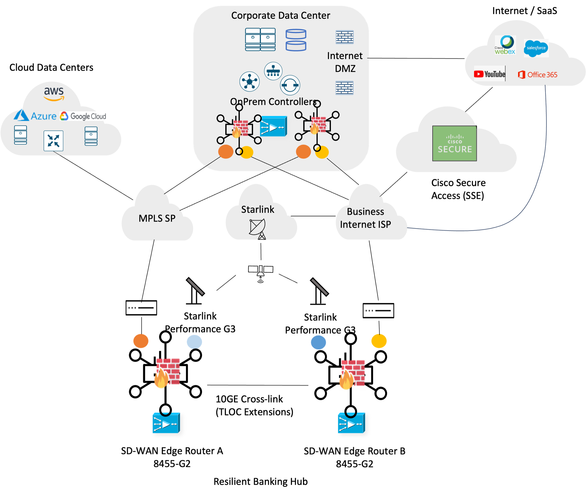
SD-WAN transport redundancy: TLOC extension design
To achieve true N+1 redundancy across both hardware and transport, the design implements Cisco Catalyst SD-WAN TLOC Extensions. This configuration logically "cross-connects" the four independent WAN circuits; Private MPLS, Business Internet (Fiber), and a pair of Starlink terminals connected to the dual C8355-G2 router stack.
Utilizing a dedicated 10GbE “cross-link” trunk between the routers, each edge platform gains native visibility into all four transport colors, regardless of which chassis the physical circuit is terminated on. This effectively creates a shared transport pool where the physical location of the circuit no longer dictates the routing capability of the individual chassis.
The orchestration of these four paths is governed by the following physical-to-logical TLOC mapping:
● Router A: Physically terminates the MPLS circuit, logically defined as tloc color ‘mpls’ and the first Starlink terminal, as tloc color ‘custom1’.
● Router B: Physically terminates business Internet, logically defined as tloc color ‘biz-internet’ and the second Starlink terminal, as tloc color ‘custom2’
Through the TLOC Extension fabric, Router A can build secure IPsec tunnels over the business Internet and second Starlink transport via Router B, and vice versa.
Facilitate advanced AAR traffic steering
The primary benefit of this "all-tunnels-on-all-routers" approach is the granular control it provides for Application-Aware Routing (AAR). Since each router maintains active control-plane sessions over every available transport, the SD-WAN fabric can make per-packet steering decisions based on real-time path telemetry (loss, latency, and jitter).
● Omni-Directional Steering: If Router A detects that the MPLS path is experiencing brownout conditions, it doesn't just fail over to its local Starlink; it can steer Gold Zone banking transactions across to Router B to utilize the Business Internet or remote Starlink paths if they meet the SLA.
● Hitless Failover: Because both routers have tunnels established over all four paths, a transport failure (like a terrestrial fiber cut) triggers a sub-second shift. The AAR policy simply redirects the flow to the next best TLOC in the existing matrix.
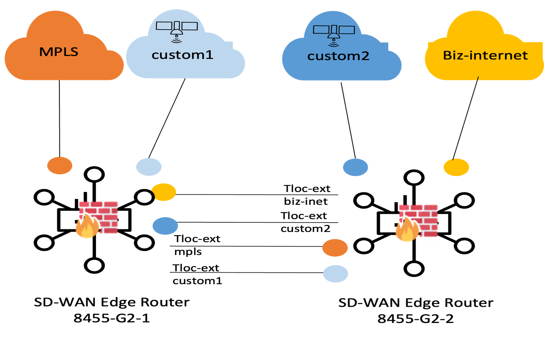
SD-WAN device configuration and policy
The following configuration represents Router A. Router B would be configured with a symmetric logic, swapping the local TLOC sub-interfaces for TLOC-extension entry points to provide Router A with access to its Business Internet and Starlink 2 circuits.
This example assumes TenGigabitEthernet0/0/2 is the trunk link between the two routers, with VLAN 101-104 to segment the four transports across the trunk. Review the Dual Router DLOC extension CLI example below:
| ! Router A configuration interface TenGigabitEthernet0/0/2.101 description TLOC biz-internet via Router B tloc-extension encapsulation dot1Q 101 ip address 169.254.101.1 255.255.255.252 interface TenGigabitEthernet0/0/2.102 description TLOC custom2 via Router B tloc-extension encapsulation dot1Q 102 ip address 169.254.102.1 255.255.255.252 ! interface TenGigabitEthernet0/0/2.103 description tloc-extension to local MPLS encapsulation dot1Q 103 ip address 169.254.103.1 255.255.255.252 ! interface TenGigabitEthernet0/0/2.104 description tloc-extension to local Starlink encapsulation dot1Q 104 ip address 169.254.104.1 255.255.255.252 ! !---Extending MPLS and custom1 for R2--------- sdwan interface TenGigabitEthernet0/0/2.103 tloc-extension GigabitEthernet0/0/1 ! interface TenGigabitEthernet0/0/2.104 tloc-extension GigabitEthernet0/0/0 ! !---Static default routes for underlay routing to TLOCs biz-internet and custom2 via Router B ip route 0.0.0.0 0.0.0.0 169.254.101.2 ip route 0.0.0.0 0.0.0.0 169.254.102.2 |
SD-WAN fabric traffic policy: Application-Aware Routing (AAR)
Application-Aware Routing is the "intelligence" of the Resilient Banking Hub. It ensures that critical financial transactions are placed in the appropriate QoS queues and always utilize the path that meets their specific latency, jitter, and loss requirements.
Tech tip: Because application portfolios and performance requirements are unique to every financial institution, this section demonstrates the simplified workflow for establishing a baseline traffic policy. Readers should adapt the specific Application Lists and SLA Classes to match their own internal compliance and performance standards.
AAR configuration workflow
In the Policy Group model, AAR is configured within the Application Priority & SLA policy.
● Define SLA Classes: Establish the performance "thresholds" (e.g., Gold_SLA for <150ms latency, Bronze_SLA for best effort).
● Create Application Lists: Group the "Financial Core" apps, "Collaboration" tools (M365), and "Business-Irrelevant" traffic.
● Define Traffic Sequences: Map each Application List to an SLA Class and preferred transport (terrestrial vs. Starlink).
Critical design consideration: Starlink bandwidth constraints
A defining characteristic of this architecture is the hybrid nature of the underlay. While the Starlink LEO Satellite provides an essential "lifeline" during terrestrial outages, it is not intended to be a 1:1 replacement for high-bandwidth Business Fiber. If all terrestrial circuits (Business Internet/MPLS) are DOWN, the aggregate bandwidth of the Starlink terminal will likely be insufficient to carry the full load of the branch. To prevent a "brown-out" that impacts high-value banking applications, the following logic is recommended:
· AAR and QoS Prioritization: Financial Core and Mission-Critical Voice must be mapped to the Starlink path with strict priority queuing.
· Selective Dropping (Bronze Class): To preserve satellite capacity for the "Gold Zone," business-irrelevant or "Bronze Class" traffic (e.g., social media, personal streaming, or large background backups) should be strictly dropped by the AAR traffic policy if the primary terrestrial paths are unavailable or SLAs are not being met.

Internet edge and cloud access
The resilient banking hub architecture implements a multi-tier Internet egress strategy designed to balance performance, cost-efficiency, and institutional security. To maintain the "never-down" mandate for high-stakes financial operations while providing modern amenities, the node utilizes a hybrid of Secure Direct Internet Access (DIA), Cisco Secure Access (SSE), and SD-WAN backhaul to the Corporate Data Center’s Internet edge security stack in the DMZ.
Low-priority guest Wi-Fi traffic is isolated into VPN/VRF 99 and offloaded via DIA, restricted to the Starlink 1 and Starlink 2 terminals to preserve bandwidth on the Business Internet circuit for core banking operations.
Mission-critical Microsoft O365 traffic isolated in VPN/VRF 10 is likewise offloaded via DIA, with preference (but not restricted to) set to the high bandwidth/low latency business Internet circuit. In the event the business Internet circuit is down or degraded, it will be allowed to fail over to the Starlink1/2 DIA paths.
Finally, all remaining corporate Internet and critical SaaS traffic in VPN/VRF10 is steered toward Cisco Secure Access (SSE) for deep-packet inspection and Zero Trust enforcement, ensuring that the bank’s security perimeter extends natively into the cloud, with the SD-WAN fabric providing a final resilient path for backhaul if cloud-security nodes are unreachable.
Table 27. Multi-tier Internet access strategy for regional banking hub
| Internet traffic class |
Preferred path |
Failover path |
Traffic redirection method |
| Guest Wi-Fi (VRF 99) |
DIA over Starlink1, Starlink 2 (load balance) |
None |
Traffic Policy redirect |
| Corp users (VRF10) to Microsoft O365 |
DIA over Business Internet |
DIA over Starlink 1/2
|
Traffic Policy redirect SD-WAN backhaul to DC as last-resort |
| Corp users to all other Internet and SaaS |
IPSec tunnel over Business Internet to Cisco Secure Access (CSA) DC |
IPSec tunnel over Starlink 1 to CSA DC SD-WAN backhaul to DC as last-resort |
Static SSE default route in VRF 10
Default route in OMP |
Coordinated resiliency policies
Secure DIA for guest users
The architecture for the Guest Wireless segment is designed to provide high-speed internet access while maintaining a "Zero-Trust" posture toward the bank’s internal systems. This is achieved by combining VRF segmentation, local DHCP services, and centralized SD-WAN controller policies.
Service-side connectivity and DHCP
Wireless clients connecting to the Guest SSID terminate on router interfaces isolated within VRF 99, leveraging VRRP across both edge routers for first-hop redundancy. To ensure localized service delivery, the primary router (8355-G2-R1) acts as the local DHCP server for this segment, providing guest devices with IP addressing, default gateway, and DNS parameters directly at the network edge.
Restrict SD-WAN fabric guest traffic
To maintain strict traffic segmentation, a centralized Topology Policy is applied at the SD-WAN controller to isolate Guest traffic (VRF 99) at the local branch. The controller explicitly filters all routes associated with the Guest VPN, preventing them from being advertised into the Overlay Management Protocol (OMP) or the broader private fabric. This configuration forces all untrusted guest data to be offloaded locally via Direct Internet Access (DIA), ensuring that corporate bandwidth is preserved for critical banking operations while maintaining total logical and physical isolation from the internal SD-WAN environment.
An example UX2.0 “Topology” defining corporate users (VPN 10) for hub-and-spoke routing, and guest users (VPN 99) routes blocked from the SD-WAN fabric is shown below.
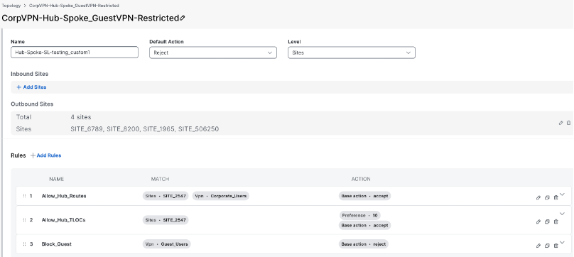
Centralized traffic policy
Guest Internet traffic in VPN 99 is redirected to the DIA path using a centralized traffic policy that matches the source data prefix list allocated to Guest users.
Tech tip: The same IP prefix range associated with guests may be used at all sites for simplicity since it is not advertised into OMP (kept local to the site) after applying the topology policy.
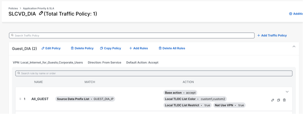
DIA for corporate VPN users to O365
Within the Corporate Segment (VPN 10), the Direct Internet Access (DIA) requirement shifts from generalized offloading to a highly granular, application-specific steering model focused exclusively on Microsoft 365.
● SaaS Policy Steering: A centralized Traffic Policy is utilized to identify Microsoft 365 (O365) traffic and dynamically reroute to a local Internet breakout utilizing the NAT-DIA engine.
● Path Preference: By utilizing a local-tloc-list pinned to the biz-internet color, O365 traffic is deterministically steered toward the terrestrial Business Fiber. This ensures the lowest possible latency for synchronous collaboration tools (Teams, Outlook) while retaining the dual Starlink paths as an automated failover mechanism should the NAT DIA tracker timeout degradation.
To maintain a rigorous security posture, all other general Internet and SaaS-bound traffic within VPN 10 is strictly prohibited from local DIA. Instead, this traffic is encapsulated and steered through the SD-WAN fabric toward Cisco Secure Access (SSE) for centralized cloud-based inspection, which will be detailed in the following section on Cloud Security.
Traffic policy for corporate VPN Microsoft O365 DIA
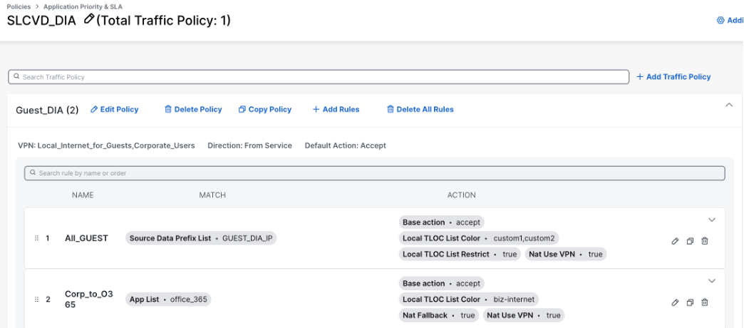
DIA resiliency challenge in Dual Router HA: Potential routing loop
In a high-availability SD-WAN architecture, the introduction of TLOC Extensions across an inter-chassis trunk creates a convenient "any-to-any" underlay. While this provides the physical path diversity required for a critical site, it introduces a risk of routing loops specifically for Direct Internet Access (DIA) traffic.
The problem arises from a logical "blind spot" between the Service VPN where the users reside and the Transport VPN (Global Routing Table), where underlay packet forwarding occurs.
When Router 1 identifies a packet destined for a SaaS application like Microsoft 365, it performs a NAT-DIA operation. This transforms the packet’s identity, pinning it to a specific Internet exit (e.g., the Business Internet circuit) that physically resides on Router 2. Router 1 then forwards this NAT translated packet across the inter-chassis trunk to its peer.
The conflict occurs when the packet arrives at Router 2. At this stage, the packet is no longer in the Service VPN; it is now in the Transport VPN (VPN 0). Router 2 then processes the packet using standard routing table rules.
Since Router 2 has multiple default routes in its global table—with Starlink2 and Business Internet next-hops reachable via local physical circuits and Starlink1 via the trunk connection to Router1—it will by default use Equal-Cost Multi-Path (ECMP) to distribute traffic. If the hashing algorithm selects a default route that points back to Router 1 (via the inter-chassis link), the packet is sent back across the trunk to Router2. This creates a recursive loop where the packet bounces between the two routers until its Time-to-Live (TTL) expires, resulting in a complete loss of connectivity for that flow.
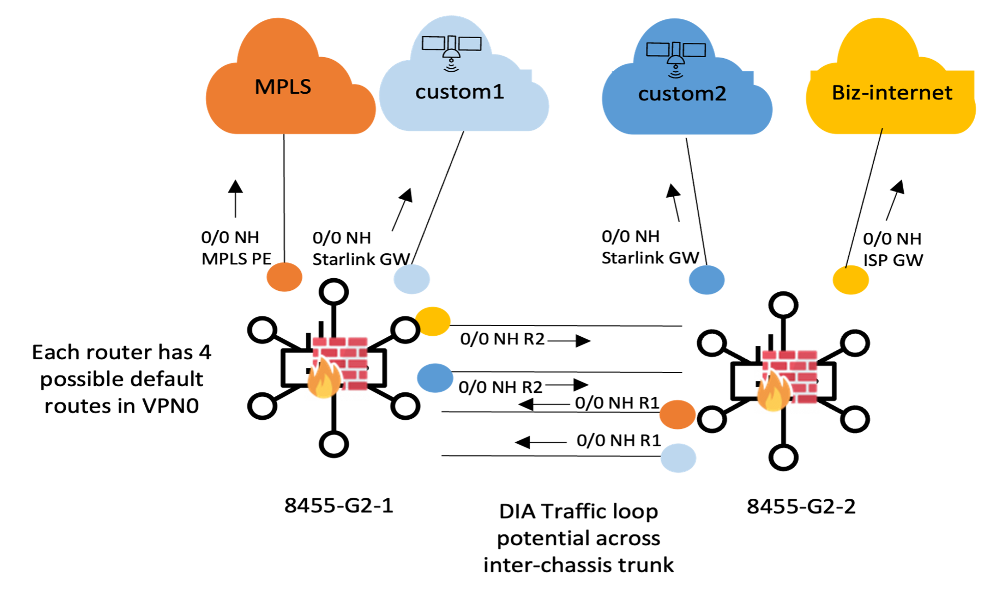
Workaround to avoid routing loop: Enhanced Policy-Based Routing (ePBR) with IP SLA tracking
To prevent inter-chassis routing loops without compromising underlay reachability, the design utilizes enhanced Policy-Based Routing (ePBR) on the TLOC-extension interfaces. This ensures that "transit" DIA traffic is handled deterministically by the router physically connected to the ISP. The Logic is as follows
● Identify the Traffic: Create an Extended ACL that matches traffic sourced from the local site peer router's IP address associated with the NAT-DIA interface on the inter-router trunk. This identifies packets that have already been processed for local Internet breakout by the other device.
● Set the Next-Hop: Create a Route Map that forces this specific traffic to the Business class ISP router’s gateway IP (1.1.1.1 in this example). To ensure high availability, use the verify-availability command tied to an IP SLA tracked object. This allows the PBR to "fall back" to the Global Routing Table (and thus the Starlink paths) if the local fiber gateway is unreachable.
● Apply to Ingress: Apply the Route Map to the TLOC-extension sub interface (the inter-chassis trunk VLAN) where the peer DIA traffic arrives. Review the following enhanced Policy Based Routing (ePBR) route map to prevent traffic looping across TLOC extension CLI:
| ePBR Configuration example (applied via cli add-on template) ! --- 1. Identify: Match Router 1's NAT Source --- ip access-list extended ACL_FROM_ROUTER_1_DIA permit ip host 169.254.101.1 any ! ! --- 2. Set: Force Local Exit with Cisco Umbrella Health Check --- ip sla 10 icmp-echo 208.67.222.222 source-interface Ten0/0/0 threshold 250 timeout 1000 frequency 5 ip sla schedule 10 life forever start-time now ! track 10 ip sla 10 reachability ! route-map RM_DIA_PBR_B permit 10 match ip address ACL_FROM_ROUTER_1_DIA set ip next-hop verify-availability 1.1.1.1 1 track 10 ! ! --- 3. Apply: Inbound on the TLOC Extension Trunk --- interface TenGigabitEthernet0/0/2.101 description INBOUND_FROM_ROUTER_1_FOR_BIZ-INTERNET ip policy route-map RM_DIA_PBR_B |
Cloud-first security: Protect financial applications with Cisco Secure Access
As the Resilient Banking Hub moves toward a cloud-centric model, the branch firewall is no longer sufficient because it lacks visibility into encrypted, off-net traffic. Protecting high-value assets, such as wealth management data, lending applications, and Salesforce flows, now requires CASB to govern cloud application usage and DLP to prevent sensitive data exfiltration, capabilities that traditional on-premises NGFWs cannot provide at cloud scale.
By offloading these streams to Cisco Secure Access, the hub moves beyond local hardware limitations to achieve cloud-scale protection. This ensures that every financial transaction is subjected to rigorous SSL/TLS decryption and Data Loss Prevention (DLP), preventing the accidental or malicious leak of customer records. Furthermore, CASB oversight provides the bank with total visibility into how employees interact with financial SaaS platforms, ensuring that the "Gold Zone" security posture remains intact even when the data resides outside the physical bank vault.
Cisco Secure Access / Secure Internet Access design
To provide a seamless path to the SSE fabric for all other corporate flows, the Cisco 8355-G2 routers utilize automated orchestration to establish a resilient Secure Internet Access (SIA) architecture. This design leverages automated IPsec tunnels to create a secure, redundant transport layer between the branch edge and the Cisco Secure Access head-end. By employing a tiered physical and logical redundancy model, the architecture ensures that encrypted security enforcement is always maintained and is never bypassed, even during local link failures.
Primary path: Terrestrial business Internet
The Business Internet circuit serves as the primary physical underlay for the IPsec SSE tunnels. This high-bandwidth terrestrial link provides the most efficient route to the Primary SSE Point of Presence (PoP). By anchoring the primary tunnels here, the branch maintains optimal performance for data-intensive financial apps while enforcing full security inspection at the cloud edge.
Backup path: Starlink LEO satellite
In the event of a terrestrial "last-mile" failure, the architecture automatically shifts traffic from the primary IPsec SSE tunnels to the secondary tunnels over Starlink transport. This ensures that even during a total local infrastructure outage, corporate traffic remains encrypted and inspected via the satellite-to-cloud path.
Cisco Secure Access PoP redundancy (primary and backup)
To protect against a regional cloud outage, the SD-WAN policy is configured with dual logical destinations:
● Primary SSE PoP: Traffic is steered to the geographically closest Cisco Secure Access data center to minimize latency.
● Backup SSE PoP: Should the primary SSE DC become unreachable or degraded, the routers automatically reroute traffic to the IPsec tunnels built to a secondary, geographically diverse Backup SSE PoP.
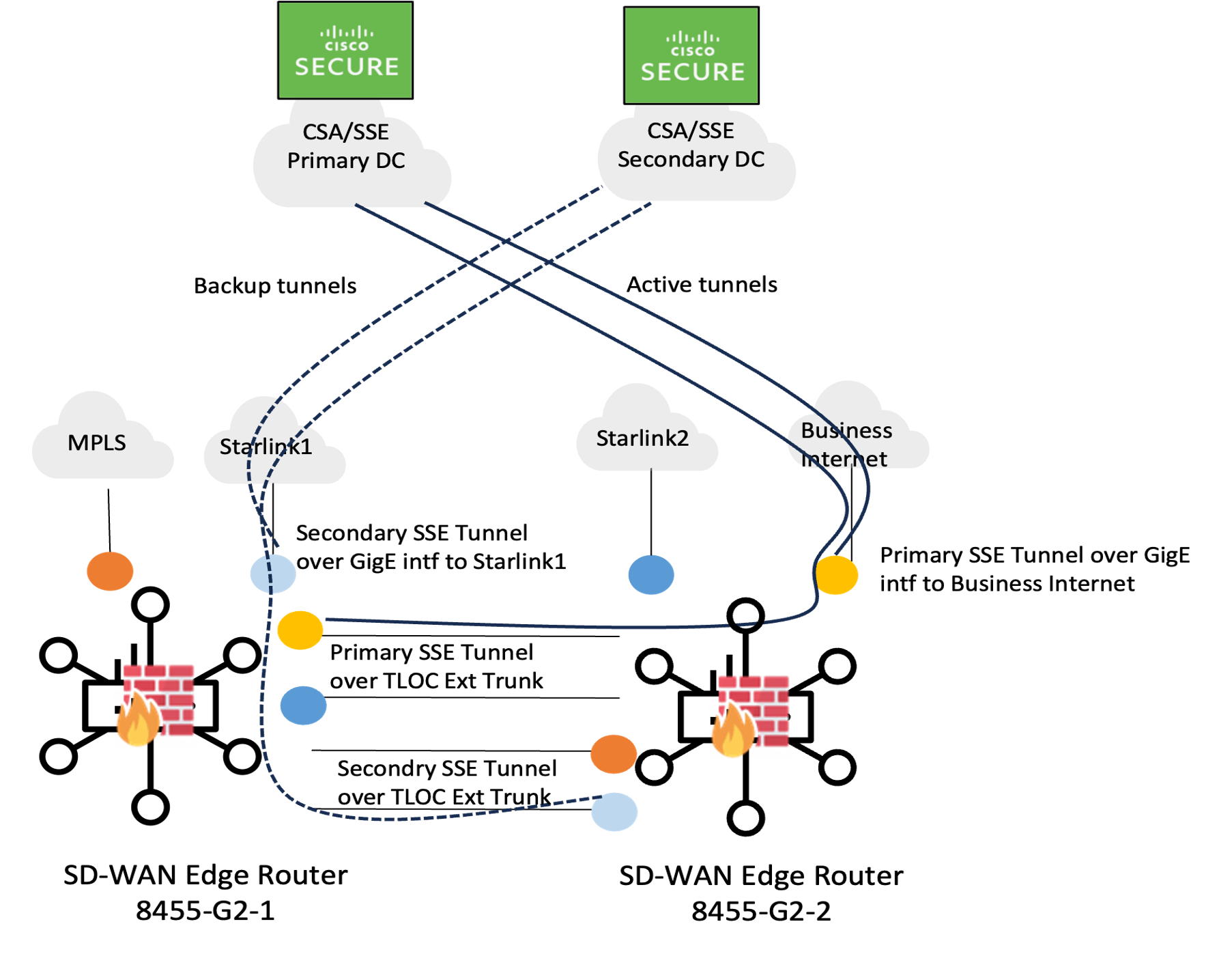
Table 28. Cisco Secure Access, Secure Internet Access configuration workflow
| Task |
UX2.0 workflow |
| Provide the Cisco Secure Access Credentials |
1. Navigate to Administration > Settings > Cloud Credentials > Add 2. Select Cisco Secure Access 3. Enter the Key and Secret (or Organization ID/Registration Key) retrieved from the Cisco Secure Access dashboard. 4. Click Save Once authenticated, the status displays "Connected." This allows the Policy to dynamically discover the available SSE PoPs. |
| Configure the Secure Internet Access (SIA) Profile |
1. Navigate to Configuration > Policy Groups. 2. Select the Policy Group 3. Select the Secure Internet Gateway / Secure Service Edge tab. 4. Click Add Secure Internet Access 5. Define the Profile and Add trackers ● Name: Give the profile a meaningful name (e.g., Banking_Hub_SIA_Profile). ● SSE Provider: Select Cisco SSE. ● Tracker Source IP address: Define a variable for the Tracker Source IP address ● Add Tracker: Define two trackers with variables for the API endpoint 6. Configure IPSec Tunnels (IPsec1 and IPsec2): ● Tunnel Source Interface: Define a variable for the Tracker Source Interface name ● Tunnel Route-Via Interface: leave as default ● Tracker: Select the tracker associated with each tunnel from the dropdown list. ● High Availability: Add Interface Pair as IPSec1 / Active and IPSec2 / Backup 7. Click Save This stage pre-stages the tunnel orchestration but does not yet steer traffic. |
| Attach the SSE Policy to the Policy Group
|
1. Navigate to Configuration > Policy Groups 2. Edit the Policy Group 3. Select the Secure Services Edge (SSE) tab. 4. Select Policy 5. In the SSE dropdown, select the SSE/SIA policy created (e.g., Banking_Hub_SIA_Policy). Automatic Association: Once selected, Manager (vManage) automatically associates the underlying SIG tunnels and cloud reachability parameters with all member devices in this group. |
| Deploy Policy |
1. Navigate to Workflows > Deploy Policy Group 2. Select Policy Group 3. Choose the Banking_Hub_Policy_Group (contains the SSE and DIA logic). 4. Select the Cisco 8355-G2 hubs managed by the Configuration Group. 5. Input device-specific values 6. Click Deploy Manager pushes the combined logic (Config Group settings + Policy Group intent) to the device. |
App-QoE over the satellite path
To maximize performance and user experience over the Starlink transports, the Resilient Banking Hub leverages a native suite of Application Quality of Experience (App-QoE) features.
● TCP Optimization: Actively manages TCP window sizes and acknowledgments locally at the edge to overcome the "long, fat pipe" characteristics of LEO satellite links.
● Forward Error Correction (FEC): Injects redundant parity packets to reconstruct data lost due to transient satellite or atmospheric interference, preventing costly retransmissions.
● Data Redundancy Elimination (DRE) and LZ Compression: Significantly reduces the payload size of recurring financial data patterns, effectively "stretching" the available Starlink bandwidth.
Enforce App-QoE traffic symmetry
Stateful App-QoE features like DRE and TCP Optimization rely on a consistent state machine; therefore, both the LAN-to-WAN and WAN-to-LAN flows must traverse the same physical router. When the forward and return legs of an application flow land on different physical routers, neither router holds a complete state entry for that session. The router that observed only the outbound SYN has no way to confirm the handshake completed, and the router that observed only the return SYN-ACK has no prior state.
In practice, this forces the optimization engine to treat the flow as untracked. It falls back to plain forwarding, silently disabling TCP Optimization and DRE for that session rather than failing loudly. While the application continues to function, it loses the WAN efficiency and latency-masking benefits the feature was deployed for. On lossy or variable-latency transports like Starlink, this often manifests as unexplained throughput variance.
Enforcing strict symmetry in a dual-router branch deployment presents a distinct challenge, as each router acts as a potential ingress and egress path for the SD-WAN fabric. In a TCP-Optimized flow originating from the service side of Router A (destined for hub servers), the return traffic sees multiple equal-cost paths to reach the branch prefix. If the overlay ECMP hash selects Router A for the return path, traffic symmetry is preserved. However, if the hash selects Router B, the router receives an unexpected SYN-ACK, optimization breaks, and throughput degrades.
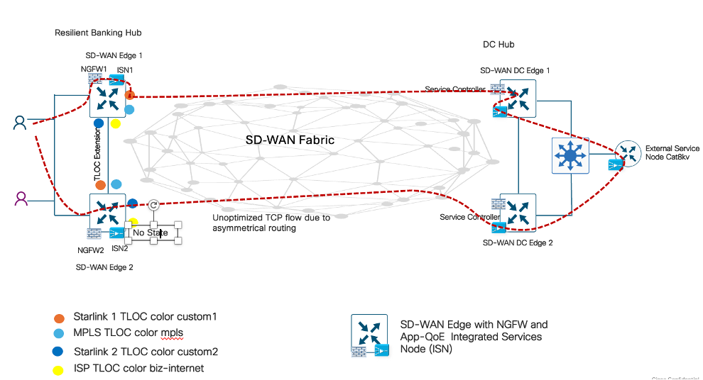
Automated symmetry via dual-router high availability
Introduced in IOS-XE 20.15/17.15, the Redundancy Group feature provides high-availability state synchronization for integrated branch services.
In this architecture, the Resilient Banking Hub utilizes a pair of Cisco 8355-G2 Secure Routers configured as Integrated Service Nodes (ISN), performing App-QoE optimization directly on-box. While it is technically feasible to deploy a distributed Service Controller and External Services Node (SC/ESN) architecture at the branch, doing so is highly impractical; it mandates dedicated compute infrastructure at the edge and introduces unnecessary operational complexity without proportional benefit. Conversely, at the Data Center hub, this distributed design is strictly required for scale, utilizing Cisco Catalyst 8500-G2s as Service Controllers (SC) that redirect heavy aggregate flows to a Catalyst 8000V (acting as the ESN) for high-capacity TCP/DRE optimization.
By binding the dual 8355-G2 routers into Redundancy Groups, the design enforces strict deterministic routing to maintain path symmetry, as the App-QoE feature itself does not synchronize TCP Optimized or FEC states across the inter-chassis link. The Redundancy Group (RG) feature orchestrates this by designating Active and Standby roles per Service VPN. For example, Router A can be configured as Active for VPN 10, while Router B acts as Standby.
To enforce symmetry, the RG actively manipulates both LAN and WAN routing protocols:
· Outbound Symmetry (LAN-to-WAN): The RG automatically adjusts the VRRP priority so that the Active router (for a given VPN) becomes the VRRP Master, ensuring it is the first hop for outbound flows.
· Inbound Symmetry (WAN-to-LAN): The Active router injects a preferred affinity attribute into OMP, steering remote sites to return traffic strictly to the Active chassis.
· Asymmetric Redirection: To handle traffic asymmetry caused by improper gateway configuration on a host, ECMP hashing, or transient routing shifts, any packets arriving at the Standby router are instantly forwarded over a dedicated inter-chassis redirect link to the Active router. This architecture ensures the Active App-QoE engine always retains complete stateful visibility of the flow, eliminating the need for complex inter-chassis state synchronization.
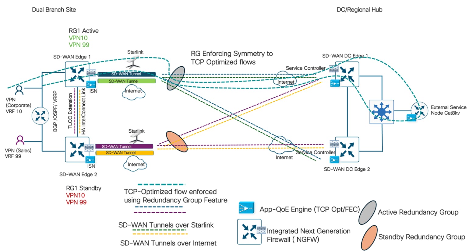
Review the product documentation for more information on the Redundancy Groups (RG) feature.
Configure redundancy group features
Within Cisco Catalyst SD-WAN Manager (UX 2.0), the policy configuration is executed in three modular steps:
Table 29. Redundancy Groups (RG) feature Workflow
| Task |
Workflow |
| Start the Workflow |
1. Navigate to Workflows > Create Configuration Group 2. Name the group 3. Set Site Type > Dual Router |
| Input the Site Configurations |
Define the Site Settings, WAN Interfaces, WAN Routing, LAN, and Service VPN Profiles. |
| Enable Dual Router High Availability |
Enable the High Availability toggle. Define which Service VPNs will be homed on which Edge Router. Define the HA Interconnect Interface (e.g., Standalone Ethernet or Port-Channel) to serve as the redirect link. |
This configuration workflow translates to the Catalyst Manager interface as shown below:
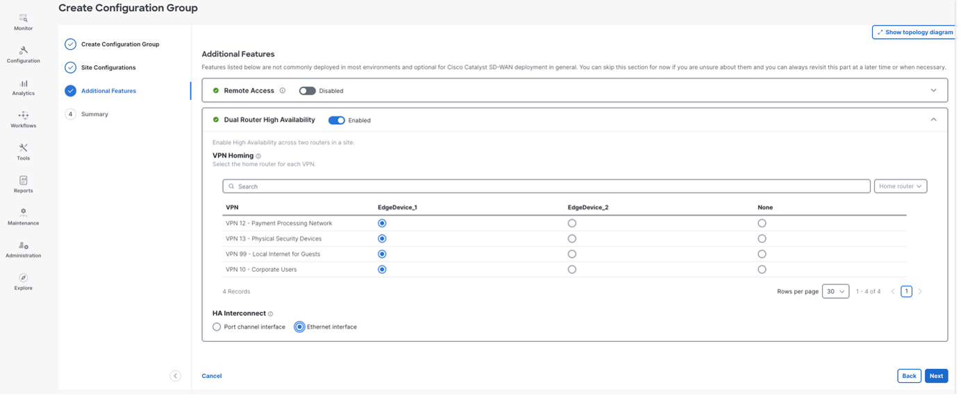
The following dual-router high availability / Redundancy Groups (RG) CLI example configurations are applied to the device:
| application redundancy group 1 control GigabitEthernet0/1/6 protocol 1 data GigabitEthernet0/1/6 asymmetric-routing interface GigabitEthernet0/1/6 path-optimization asymmetric-routing always-divert example track-enable 600 init-role primary vpn 99 vpn 10 |
Enforce LAN-to-WAN symmetry with VRRP tracking Redundancy Group state
To maintain path symmetry in the LAN-to-WAN flow direction, VRRP is configured to track the Redundancy Group. This ensures the active VRRP gateway dynamically follows the Active optimization node, naturally aligning the inbound traffic path. This is achieved by following the workflow below:
Table 30. VRRP tracking Redundancy Groups (RG) state workflow
| Task |
Workflow |
| Navigate to the CG created for HA Branch |
Navigate to Configuration > Configuration Group |
| Edit the Service Profile |
Navigate to Service Profile > Ethernet Interface |
| Edit the Ethernet Interface VRRP sub feature parcel |
Navigate to Ethernet Interface > VRRP > Enable the knob Follow dual router high availability |
This configuration workflow translates to the Catalyst Manager interface as shown below:
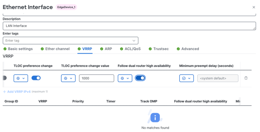
To verify that the Redundancy Group is actively managing path symmetry, validate the state machine directly from the branch router CLI:
| Banking-Hub-8355-R1# show redundancy application group 1 Group ID:1 Group Name: Banking_Hub_HA
Administrative State: No Shutdown Aggregate operational state : Up My Role: ACTIVE Peer Role: STANDBY Peer Presence: Yes Peer Comm: Yes Peer Progression Started: Yes Path Optimization: Enabled TLOC Pref Change: 0
RF Domain: btob-one RF state: ACTIVE Peer RF state: STANDBY HOT
Banking-Hub-8355-R1# show vrrp vlan 10 Vlan10 - Group 202 - Address-Family IPv4 State is MASTER State duration 8 mins 4.480 secs Virtual IP address is 10.2.1.254 Virtual MAC address is 0000.5E00.01CA Advertisement interval is 1000 msec Preemption enabled Priority is 100 State change reason is VRRP_MASTER_NO_RESP Tloc preference configured, value 1000 Track object 600 state UP decrement 10 Master Router is 10.2.1.252 (local), priority is 100 Master Advertisement interval is 1000 msec (expires in 422 msec) Master Down interval is 3609 msec FLAGS: 1/1
If a failure occurs or if Router 1 is reloaded, the Redundancy Group immediately shifts roles. The following logs will appear on Router 2:
*Jun 30 18:17:15.403: %VRRP-6-STATE: Vlan10 IPv4 group 202 state BACKUP > MASTER *Jun 30 18:17:19.564: %LINK-3-UPDOWN: Interface GigabitEthernet0/1/6, changed state to down *Jun 30 18:17:19.567: %RG_PROTOCOL-5-ROLECHANGE: RG id 1 role change from Standby to Active
Note: This forces Router 2 to become Active for RG 1, which in turn forces its VRRP state to Master. Even after Router 1 recovers, Router 2 remains the VRRP Master because VRRP is bound to the Redundancy Group state rather than its default priority and preemption behavior. Consequently, LAN-side traffic always exits through the Active RG candidate, enforcing symmetry for outbound flows leaving the SD-WAN fabric. |
Routed LAN Deployments: In Layer 3 topologies utilizing a downstream LAN router, path symmetry is achieved via IGP Rewrite rather than VRRP. By using the redistribute omp translate-rib-metric command, the active router translates OMP-learned metrics directly into its LAN-facing OSPF or BGP advertisements. This establishes the active node as the preferred next-hop, naturally steering LAN traffic to the correct App-QoE engine without relying on a virtual gateway.
The following illustrates an example with OSPF:
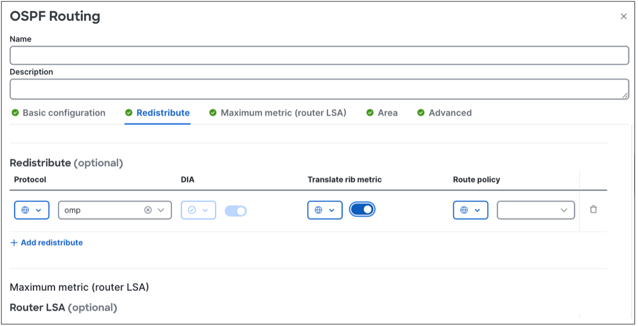
To enforce symmetry for incoming traffic from the overlay, the Data Center must know which branch router is currently holding the Active RG role. This is achieved by configuring the affinity group preference as shown in the following workflow.
Table 31. Affinity Group configuration workflow for WAN-to-LAN symmetry in dual router HA deployments
| Task |
Workflow |
| Navigate to Branch Config |
Navigate to Configuration > Configuration Group (Select the HA Branch group) |
| Edit the System Profile |
Select System Profile > Basic |
| Enable Affinity Group |
Navigate to Basic > Controller settings Enable "Affinity group preference auto" |
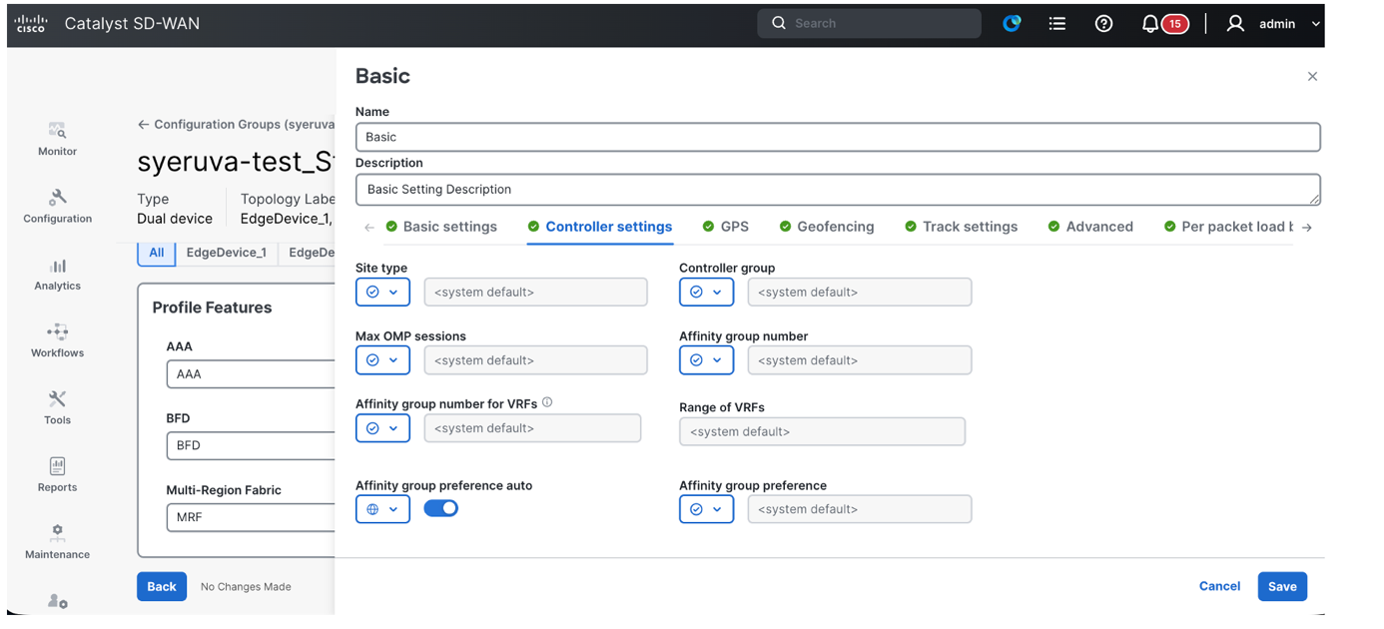
The following Affinity group preference CLI is sent to the device:
| CLI Equivalent system affinity-group preference-auto |
When configured, the Active RG candidate router dynamically announces the lowest affinity value. When the Data Center routers evaluate the OMP routes for the branch prefix, they always prefer the tunnel sourced from the router broadcasting that lowest affinity, thereby controlling the direction of incoming flows.
Monitor WAN-to-LAN symmetry from hub routers
The output below confirms that Router 2 (System IP 192.168.25.66) has transitioned to the Active RG role. The DC Router shows a preference for this chassis, tagged with Affinity Group 1.
| DC-HUB-Cat8500-1# show sdwan omp routes 10.2.1.0/24 Code: C > chosen I > installed R > resolved SYS AFFINITY PATH PATH ATTRIBUTE GROUP TENANT VPN PREFIX FROM PEER ID ID LABEL STATUS TYPE TLOC IP COLOR ENCAP PREFERENCE NUMBER REGION ID REGION PATH ------------------------------------------------------------------------------------------------------------------------------------------------------------------------------------------------ 0 10 10.2.1.0/24 192.168.250.43 78 4521 1005 R installed 192.168.25.44 custom1 ipsec - 2 None - 192.168.250.43 78 4974 1005 C,I,R installed 192.168.25.66 custom1 ipsec - 1 None - 192.168.250.43 79 4521 1005 R installed 192.168.25.44 custom2 ipsec - 2 None - 192.168.250.43 79 4974 1005 C,I,R installed 192.168.25.66 custom2 ipsec - 1 None - 192.168.250.43 4521 0 1005 R installed 192.168.25.44 - - - 2 None - 192.168.250.43 4974 0 1005 R installed 192.168.25.66 - - - 1 None - |
Stateful App-QoE features like TCP Optimization and DRE depend on a single router observing both legs of a flow. Because the optimization engine is not inherently high-availability aware across dual chassis, asymmetrical routing breaks that fundamental precondition. When flows split across two physical routers, the optimization engine fails to track the TCP state and silently falls back to unoptimized forwarding. This undermines the very throughput, and latency benefits the feature was deployed to provide, which is a degradation that is particularly noticeable on lossy, latency-prone transports like LEO Starlink.
The Redundancy Group feature closes this gap by enforcing physical path symmetry in both directions:
● LAN-Side: VRRP is dynamically linked to the Redundancy Group state, ensuring outbound traffic always exits through the Active RG candidate router rather than defaulting to static priority metrics.
● WAN-Side: The affinity-group preference-auto configuration ensures that the Data Center routers consistently select the currently Active branch router as the return next-hop.
● Inter-Chassis Redirection: Should transient overlay hashing cause a packet to land on the Standby router, it is immediately shunted over the dedicated inter-chassis redirect link to the Active router.
Together, these mechanisms guarantee that both legs of every TCP-Optimized flow (LAN-to-WAN and WAN-to-LAN) are processed by the exact same physical router for the lifetime of the session, regardless of the number of active transports or overlay conditions. By making strict path symmetry a structural property of the architecture, the Resilient Banking Hub successfully eliminates the throughput degradation caused by asymmetric ECMP hashing, ensuring that high-value financial applications operate flawlessly over hybrid terrestrial and satellite underlays.
Multicast overlay routing for real-time market data
To support financial trading feeds, the architecture utilizes Cisco SD-WAN Multicast Overlay Routing, leveraging head-end hub routers to act as centralized multicast replicators. This design completely offloads the replication burden from local service provider networks and resource-constrained branch edges. The centralized hubs receive the core multicast streams and dynamically replicate the traffic into unicast IPsec tunnels for secure distribution across the fabric. By handling replication at the head-end hub layer, the network ensures deterministic, synchronized delivery of real-time market data across diverse underlays without requiring native multicast support from transit service providers.
The SD-WAN control plane utilizes the Overlay Management Protocol (OMP) as a translation layer, eliminating the need for traditional Protocol Independent Multicast (PIM) adjacencies across the WAN. When a branch router receives a local PIM Join message, it translates that state into an OMP Multicast Route and notifies the controller. The controller builds a topology map of sources and receivers, programming the replicators with the necessary branch destination lists. This allows the replicator to encapsulate incoming multicast traffic and transmit it to requesting branches via the SD-WAN overlay.
Because the multicast replicator delivers these streams via unicast tunnels, the traffic is fully eligible for Application-Aware Routing (AAR) policies. By defining specific SLA classes for the multicast market data, the SD-WAN controller monitors tunnel performance, such as jitter and latency, to steer traffic toward preferred terrestrial transports. This setup enables the use of "Preferred Color" affinities, ensuring high-bandwidth feeds prioritize fiber circuits and only utilize Starlink LEO links as a last resort, preventing satellite link saturation while maintaining high availability.
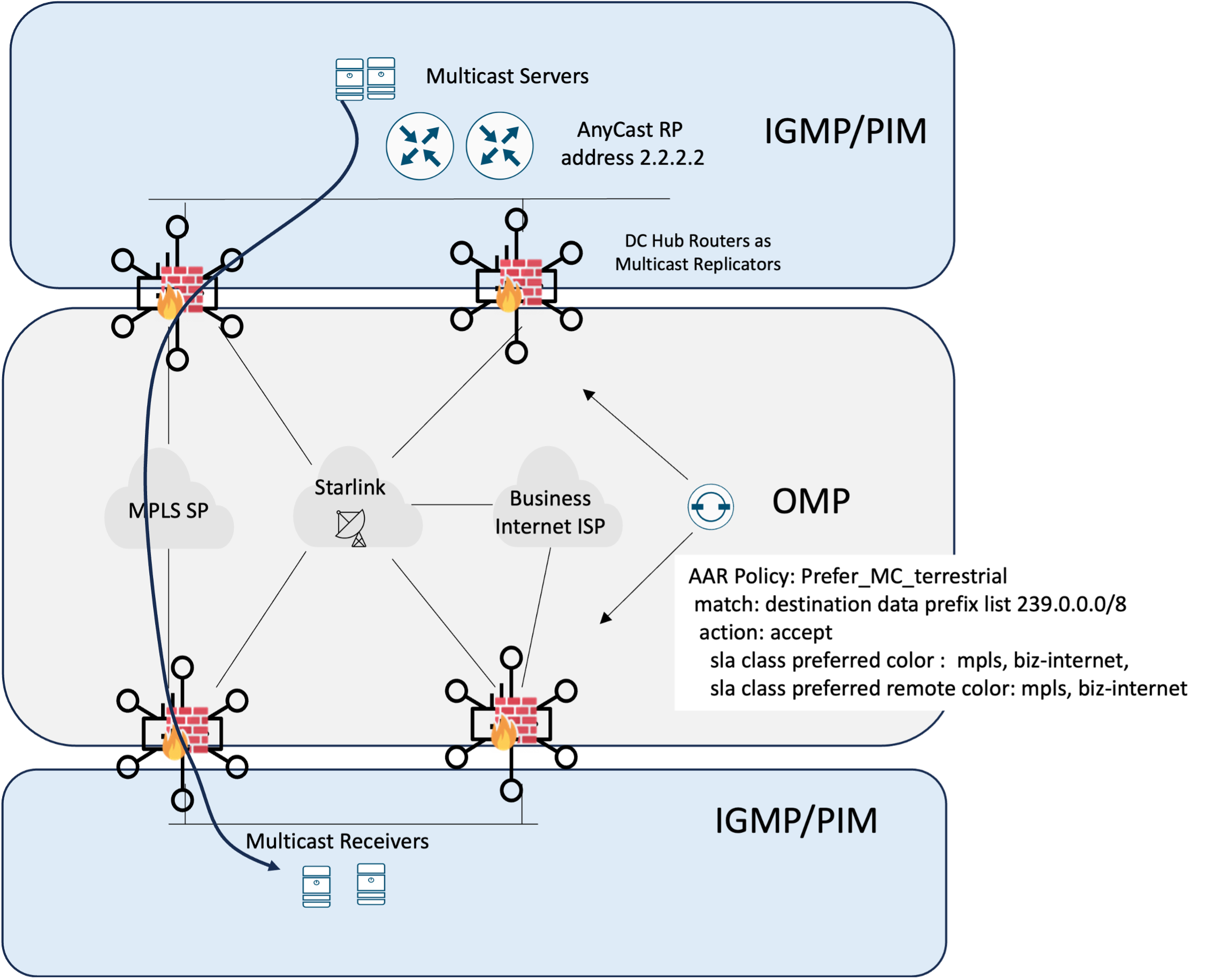
Table 32. Multicast Overlay Configuration Workflow.
| UX2.0 Workflow task for branch multicast |
UX2.0 Workflow task for hub multicast |
| Configuration > configuration groups > branch CG > edit service profile |
Configuration > configuration groups > Hub CG > edit service profile |
| Click on the + next to the Service VPN and add Multicast. Select + and add new. Provide a name and description |
Click on the + next to the Service VPN and add Multicast. Select + and add new. Provide a name and description |
| Navigate to the PIM section and leave Basic Settings (SPT-only, Replicator) at default. Navigate to interfaces, click “add interface” and specify Service VPN interface(s) |
Navigate to the PIM section enable local replicator. Navigate to interfaces, click “add interface” and specify Service VPN interface(s) |
| Navigate to “How do you want to configure your Rendezvous Point (RP)” and select “static”. Specify the AnyCast IP address (2.2.2.2) used by the RP pair in the DC |
Navigate to “How do you want to configure your Rendezvous Point (RP)” and select “static”. Specify the AnyCast IP address (2.2.2.2) used by the Rendezvous Point (RP) pair in the DC |
Table 33. Application-aware routing traffic steering for Multicast traffic configuration workflow.
| Task |
UX2.0 policy workflow |
| Create a data prefix list that matches the IP address range for private multicast (e.g., the 239.0.0.0/8 administratively scoped block) |
1. Navigate to Configuration > policy groups > objects and policies > data prefix list > add new 2. Provide name (Private_Multicast_Range) 3. Enter 239.0.0.0/8 |
| Add a new sequence to the Application Priority and SLA traffic policy |
1. Navigate to Configuration > policy groups > Application Priority SLA traffic > add rule match: destination data prefix list Private_Multicast_Range action: accept sla class preferred color : biz-internet, mpls sla class preferred remote color: biz-internet, mpls |
An example AAR policy sequence for multicast traffic steering is shown below.

Application, QoS, AAR, and egress policy matrix
The following consolidated matrix provides a single reference for how each major application class is handled across the branch architecture. It aligns application hosting, VRF and QoS treatment, AAR path selection, Internet egress, multicast requirements, and supporting policy controls, while identifying proposed values and items that require validation before implementation.
Table 34. Banking application business-intent and network policy matrix
| Application / hosting |
VRF/QoS |
AAR SLA / path |
Internet egress |
Multicast |
Other policy / validation |
| Core banking transactions; ATM and card-issuance services / On-prem DC |
VRF 10 / AF21 (18) |
Gold_Transactional
MPLS + Business Internet preferred; Starlink custom1/custom2 fallback |
No local Internet breakout; private SD-WAN overlay |
No |
AAR + QoS; RG symmetry; App-QoE only with paired endpoints; validate failover and capacity |
| VDI (virtual desktops) /On-prem DC |
VRF 10 / AF21 (18) |
Business_Critical thresholds TBD |
No local Internet breakout; private SD-WAN overlay |
No |
AAR; TCP optimization may help eligible flows; DRE requires paired endpoints and release/resources |
| Real-time market-data feeds |
VRF 10 / CS4 (32) |
Business_Critical
MPLS + biz-internet preferred/remote preferred; Starlink last resort |
No local Internet breakout; private SD-WAN overlay |
Yes administratively scoped groups within 239.0.0.0/8 |
AAR multicast supported; define source/group boundaries, RP resiliency, rate limits, and Starlink admission behavior |
| Branch voice bearer (branch to branch and HQ) |
VRF 10 / EF (46), priority queue |
Voice_RealTime
|
No local Internet breakout; private SD-WAN overlay |
No |
Admission control and LLQ policer required; do not let aggregate priority traffic starve other classes |
| Microsoft Teams real-time media / SaaS |
VRF 10 / |
AAR: N/A after DIA breakout |
Policy-based DIA |
No |
Preserve/remark DSCP at the trusted edge; validate NAT tracker and ePBR loop prevention; size queues and admission; do not treat all M365 traffic as one QoS class |
| Outlook, SharePoint, OneDrive, other M365 productivity / SaaS |
VRF 10 / Default (0) |
AAR: N/A after DIA breakout |
Policy-based DIA |
No |
Separate large OneDrive transfers from interactive traffic if congestion testing warrants it |
| Salesforce and other approved critical SaaS/ |
VRF 10 /AF21 (18) for explicitly approved SaaS transactions; otherwise, 0 |
AAR: N/A after SSE breakout; egress selected by data policy, routing, and tunnel/tracker health |
Cisco Secure Access; SSE policy redirect |
No |
CASB/DLP/TLS policy applies only to selected redirected flows; confirm fail-open/fail-closed and fallback-to-routing |
| Wealth-management and lending applications |
VRF 10 / AF21 (18) |
AAR: N/A after SSE breakout; egress selected by data policy, routing, and tunnel/tracker health |
Cisco Secure Access; SSE policy redirect |
No |
Inventory each FQDN/app ID/dependency; the section currently cannot determine one policy for this combined label |
| General corporate Internet and SaaS |
VRF 10 / Default (0) |
AAR: N/A after SSE breakout |
Cisco Secure Access; SSE policy redirect |
No |
Explicit default/fallback route ownership; Secure Access tunnel trackers; avoid policy bypass |
| Guest Wi-Fi |
VRF 99 / Default (0) |
AAR: N/A after DIA breakout |
Policy-based DIA |
No |
Topology isolation; local DHCP/VRRP; NAT; DNS/security policy; consider per-user rate limits and a captive portal |
| Backups / bulk transfers |
VRF 10 / AF11 (10) for managed bulk; CS1 (8) if intentionally scavenger |
Bulk; Terrestrial only when possible; drop/defer on Starlink during constrained mode |
Policy-based DIA when cloud |
No |
Schedule windows, shaping, and explicit satellite suppression; do not combine business backups with recreational traffic operationally |
| Social media / personal streaming / business-irrelevant |
VRF 10 and VRF 99 |
Bronze; Strict/Drop when preferred SLA/path unavailable Terrestrial if permitted; drop on Starlink constrained |
Corporate VRF: security policy/SSE or deny; guest VRF: DIA |
No |
URL/app control, acceptable-use policy, rate limiting; confirm that the rule's SLA-name text is not truncated in production documentation |
High-capacity and multi-terminal
This profile is engineered for high-bandwidth, mission-critical environments where terrestrial infrastructure is either non-existent, or where LEO is utilized as a high-speed redundant path to traditional land-based circuits. Designed for maritime, offshore, and large-scale corporate campuses, this architecture leverages bandwidth aggregation through load-sharing across multiple LEO terminals to deliver the throughput required to sustain hundreds of concurrent users and mission-critical business telemetry. It is purpose-built for primary connectivity or where the cost of downtime is extreme, and the upstream (transmit) demand exceeds the physical limitations of a single satellite terminal.
● Cruise Ship / Maritime Vessel: A floating city requiring high-density Guest Wi-Fi, crew communications, and real-time synchronization of ship-to-shore operational data and navigational systems.
● Offshore Oil & Gas Rig: A remote industrial outpost relying on constant streams of sensor telemetry, high-definition safety surveillance, and secure ERP access for logistics and supply chain management.
● Mission-Critical Site: A primary regional hub or processing facility that requires a high-capacity backup to terrestrial fiber. In the event of a catastrophic fiber cut, regional service provider outage, or physical sabotage.
Multi-terminal aggregation and SD-WAN at sea
A modern super-class cruise vessel is effectively a floating, hyper-connected smart city. With upward of 7,000 passengers and crew embarking on a single voyage, the legacy paradigm of high-latency, easily congested maritime satellite connectivity is no longer viable. Today's passengers expect concurrent 4K streaming, frictionless mobile applications, and instant social media connectivity.
The resulting traffic profile is fundamentally asymmetrical. Approximately 60% of the vessel's aggregate bandwidth is dedicated to Direct Internet Access (DIA) for guest Wi-Fi and crew communications. The remaining 40% requires SD-WAN transport for mission-critical ship-to-shore telemetry and corporate point-of-sale systems.
To satisfy these massive throughput requirements while maintaining strict isolation of critical maritime systems, this architecture leverages a 14-terminal Starlink array yielding over 4 Gbps of downstream and 700 Mbps of upstream capacity, complemented by existing legacy shipboard backhaul for ultimate transport diversity.
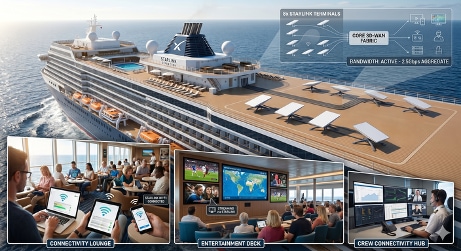
Architecture, hardware, and configuration summary
Deploying a high-density Starlink array on a single enterprise router introduces constraints that standard SD-WAN designs do not typically encounter. Overcoming Starlink's single-terminal delivery model requires solving three primary challenges:
1. Addressing and Gateway Overlap: Because Starlink uses dynamic DHCP via regional ground stations, it is a mathematical certainty in a 14-terminal array that multiple terminals will receive overlapping IP subnets or identical upstream gateways (e.g., the 100.64.0.1 CGNAT gateway). Standard Cisco IOS-XE routing rules prohibit overlapping subnets and identical next-hops across different physical interfaces in the same VRF, requiring strict, logical isolation.
2. Missing Link Aggregation (LACP): Current Starlink terminals do not support IEEE 802.3ad (LACP) or Multi-Chassis Link Aggregation (MC-LAG). Because the Ethernet links cannot be bonded at Layer 2 into a single Port-Channel, the responsibility for load balancing shifts entirely to Layer 3 and the SD-WAN overlay.
3. Control Plane Sprawl (The 8-TLOC Limit): While Cisco Secure Routers possess the physical port density for 14 terminals, Cisco SD-WAN architecture recommends a maximum of 8 TLOCs per edge device. Exceeding this limit introduces Overlay Management Protocol (OMP) path sprawl and unnecessary CPU overhead.
Solution architecture: Two-tier intelligent aggregation strategy
To safely scale the 14-terminal array and provide the capacity required to support the vessel's 60/40 (DIA-to-Corporate) traffic split, this architecture utilizes a Two-Tier strategy: an Aggregation Tier to manage the physical satellite underlay, and an SD-WAN Edge Tier to manage the overlay.
To eliminate control plane sprawl and provide hardware redundancy, both tiers are horizontally scaled across dual routers, interconnected via full-mesh of 10Gbs, 802.1Q trunks. Logical sub-interfaces are provisioned across these trunks to safely separate SD-WAN TLOCs from native Direct Internet Access (DIA) breakout traffic.
Aggregation tier (underlay management)
This layer terminates the satellite Ethernet connections, normalizes them, and strictly enforces the traffic segmentation. Out of the 14 terminals, 10 are dedicated strictly to guest DIA, and 4 are dedicated to corporate SD-WAN transport.
VRF-lite segmentation: Each Starlink connection terminates into a dedicated Front Door VRF (FVRF) to isolate overlapping gateways and IPs. The aggregation device then hands off unique /30 transit subnets to the SD-WAN Edge via the trunked sub-interfaces.
Dual-purpose OSPF origination and centralized NAT: OSPF serves a critical dual role in handing off underlay routing to the SD-WAN Edge:
● For Guest Internet default routing (Service VPN 99): To service guest internet without consuming SD-WAN TLOCs, the Aggregation router performs traditional NAT at the Internet edge, leveraging OSPF to originate multiple default routes directly into the SD-WAN Edge's Guest Wi-Fi Service VPN. Standard OSPF Equal-Cost Multi-Path (ECMP) natively load-balances this guest traffic across the Starlink terminals designated for DIA, eliminating the need for complex centralized SD-WAN policy.
● For SD-WAN TLOC default routing (Transport VPN 0): For the 4 dedicated corporate terminals, the Aggregation router uses OSPF to announce the default route into the SD-WAN Edge's global routing table (VPN 0). This provides the essential transport reachability the Edge router requires to establish its IPsec TLOCs over those specific satellite paths.
Note: Corporate Internet access uses the same Starlink terminals as the SD-WAN TLOCs. The access method could be NAT-DIA or backhaul over the SD-WAN path to a terrestrial Internet gateway site.
Dynamic failover via IP SLA tracking: To prevent traffic blackholing during satellite obstructions, IP SLA object tracking continuously monitors the upstream Starlink gateways across all links. If a probe fails, the router dynamically withdraws the default route associated with that specific Starlink FVRF. OSPF immediately updates, gracefully shifting guest traffic to healthy DIA terminals, or signaling the SD-WAN Edge to instantly failover corporate traffic to a healthy TLOC.
"Services Sandbox": The aggregation tier provides the capabilities to natively host IP SLA, Embedded Event Manager (EEM) scripts, ThousandEyes Enterprise Agents, and Cisco IOx containers, alongside provisioning SPAN ports for localized deep-packet traffic monitoring.
SD-WAN overlay (traffic and application management)
By abstracting the underlay complexity, the SD-WAN Edge tier transforms the normalized FVRF paths into a highly resilient corporate fabric. The Edge router simply consumes the OSPF routes provided by the Aggregation tier, utilizing the Service VPN routes for scalable guest internet and utilizing the VPN 0 routes to build the SD-WAN overlay tunnels. Given the lack of "elephant flows" traversing the corporate overlay, standard per-flow (5-tuple) hashing provides excellent load distribution across the dedicated SD-WAN terminals.
· Enhanced Application-Aware Routing (eAAR): Dynamically shifts corporate traffic between the active/backup SD-WAN TLOCs and legacy shipboard backhaul based on real-time latency, loss, and jitter measurements
· TCP Optimization: Masks satellite loss and latency to prevent TCP throttling and "slow start" issues.
· Forward Error Correction (FEC): Reconstructs lost packets using parity data, mitigating the impact of transient LEO packet loss without requiring retransmissions.
· Data Reduction (DRE/LZ): Uses aggressive caching and Lempel-Ziv compression to reduce total WAN consumption by 30–50%, preserving valuable corporate bandwidth.
Hardware recommendations
Aggregation tier hardware
The selected platform must provide adequate 1 Gigabit Ethernet (1GE) port density to terminate the downstream Starlink terminal connections, paired with 10GE or 25GE uplinks for the high-bandwidth inter-tier Port-Channels. Additionally, the routing feature set must support VRF segmentation and VRF-aware NAT to ensure proper traffic isolation. To meet these scale and feature requirements using the latest generation of secure routing hardware, recommended platforms include:
· Cisco C8455-G2 Secure Router: Ideal for a dual-aggregation design, this 1RU platform provides 8x 1GE SFP ports to terminate the satellite array, paired with 2x 10GE and 2x 25GE ports for high-capacity uplink connectivity.
· Cisco C8475-G2 Secure Router: For environments requiring higher density on a single chassis, this platform provides up to 16 ports capable of 1GE (8x 1GE SFP and 8x 1/10GE SFP+), alongside 4x 25GE ports for inter-tier handoffs.
· Cisco Catalyst 8300 Series (Modular): For modular flexibility, the Catalyst 8300-1N1S-4T2X or 8300-2N2S-6T can be equipped with expansion modules (SM-X/NIM) to scale up to 24 routed 1GE ports and multiple 10GE uplinks.
SD-WAN tier hardware
App-QoE features like Data Redundancy Elimination (DRE) and LZ compression require a hardware architecture optimized for intensive service-plane computation and fast disk I/O.
Recommended Platforms: Cisco C8475-G2 and C8455-G2 Secure Routers
· High-Performance Crypto: The 8000 series secure router platform features a dedicated secure networking processor that delivers up to 45 Gbps of IPsec throughput. This offloads the encryption of the corporate SD-WAN tunnels, preventing CPU exhaustion.
· M.2 NVMe Storage for DRE/LZ: A 600GB or 2TB SSD upgrade is strictly required. This provides the high-speed storage necessary to build the DRE redundancy cache, execute LZ compression, and store ThousandEyes logs.
· Zero-Oversubscription Handoffs: Both the C8455-G2 and C8475-G2 deliver the 10G/25G (SFP28) port density required to terminate the high-availability Port-Channels from the Aggregation Tier without physical bottlenecks.
· DRAM Scalability: The native 32GB of memory can be expanded to 64GB to support extensive DRE caching as vessel traffic scales.
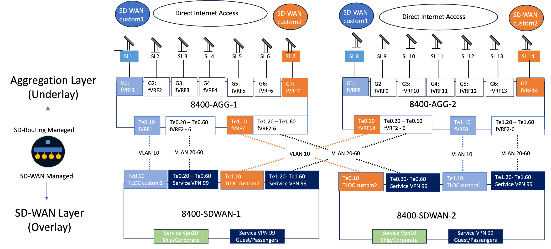
Reference configuration summary
The following summarizes the intent and configuration highlights of the Multi-Terminal Aggregation and SD-WAN Edge routers. Refer to Appendix A for full CLI configurations and Appendix B for monitoring commands.
Multi-terminal aggregation router
Objective: To manage the physical connections of the high-density Starlink array, normalize overlapping IP space, and provide a stateful, abstracted underlay that protects the downstream SD-WAN Edge from link flapping and control plane exhaustion.
Configuration highlights
· FVRF Segmentation: Isolates each Starlink terminal into a dedicated Front-Door VRF (fVRF), preventing routing conflicts caused by overlapping DHCP assignments and identical gateways.
· Dual-Purpose OSPF Origination: Utilizes OSPF to advertise underlay reachability across the trunk, providing VPN 0 routes for TLOC establishment and Service VPN 99 routes for guest internet.
· Stateful Link Tracking: Leverages IP SLA to continuously monitor upstream gateway health. Instead of interacting directly with the DHCP default route, tracking is tied to a static "dummy route," acting as a flawless trigger for OSPF withdrawals during satellite obstructions.
· Centralized Guest NAT: Offloads Direct Internet Access (DIA) translation for passenger traffic directly to the physical edge, ensuring high-volume guest traffic never touches the SD-WAN overlay or consumes Edge router CPU cycles.
· Guest Perimeter Security (NGFW): Because the Starlink terminals dedicated to guest DIA offload passenger traffic natively at the Aggregation Tier, the security boundary must also be enforced here to prevent malicious or bandwidth-abusive traffic from saturating the satellite underlay. Managed via Cisco Catalyst SD-Routing, the Aggregation routers run a localized Next-Generation Firewall (NGFW) stack. This enforces Layer 7 application visibility, category-based URL filtering (to block high-consumption recreational traffic like P2P or unauthorized HD streaming), and Intrusion Prevention (IPS) directly on the guest interfaces. By scrubbing the traffic at the physical edge, the architecture secures the vessel's localized guest network without needing to hair-pin passenger data through the SD-WAN Edge tier.
SD-WAN edge router
Objective: The primary objective of the Two-Tier architecture is to bypass the 8-TLOC limit without sacrificing capacity. By abstracting the physical Starlink array behind the Aggregation Tier, the SD-WAN Edge is insulated from underlay scale limitations and physical connection failures.
Configuration highlights
· Air-Gapped VRF Architecture: Enforces strict, logical separation between the Corporate Ship network (VPN 10) and the Guest Passenger network (VPN 99), ensuring passenger traffic physically cannot route over the corporate IPsec TLOCs.
· Symmetrical VLAN Mapping: Aligns 10G trunk sub-interfaces (e.g., VLAN 10, 20, 30) directly with their corresponding Aggregation tier FVRFs, creating a highly readable and mathematically consistent configuration for Day 2 operations.
· Corporate DIA Route Leaking: Employs NAT with the global keyword to securely leak trusted corporate web traffic (e.g., Office 365) from Service VPN 10 out to the Transport VPN 0 underlay, preventing unnecessary hair-pinning over the overlay.
· Abstracted Traffic Steering: By ingesting normalized OSPF underlay paths, the Edge router can seamlessly apply centralized vSmart policies, including Enhanced Application-Aware Routing (eAAR), Forward Error Correction (FEC), and App-QoE, without complex local policy-based routing.
· Guest Perimeter Security (NGFW): Enforces Layer 7 firewalling, IPS, and URL filtering via SD-Routing management directly at the Internet breakout point. This ensures passenger traffic is scrubbed and restricted by maritime acceptable-use policies before it can consume the Starlink satellite capacity, completely isolating untrusted web traffic from the SD-WAN edge.
Strategic outcomes and NTN
The integration of Low Earth Orbit (LEO) satellite transport has evolved from a tactical necessity for remote reachability into a foundational pillar of enterprise resilience. As this blueprint demonstrates, pairing the high-capacity, low-latency underlay of Starlink with the intelligent, software-defined orchestration of Cisco Catalyst SD-WAN decouples business continuity from the physical vulnerabilities of terrestrial infrastructure.
We are entering a new era of Non-Terrestrial Networks (NTN), where the edge is no longer strictly bound to the ground. By combining purpose-built hardware, such as the Cisco 8000 Series Secure Routers, with advanced App-QoE and Post-Quantum Cryptographic (PQC) readiness, enterprises can transform highly variable satellite links into hardened, deterministic transport. Whether recovering packets seamlessly via Forward Error Correction or drastically accelerating TCP flows, driving throughput from a baseline of 55 Mbps to over 200 Mbps, Cisco SD-WAN ensures that the satellite path mirrors the performance and security expectations of a Tier-1 headquarters.
Architectural summary and strategic takeaways
The deployment profiles detailed in this guide, from zero-footprint mobile environments to the two-tier intelligent aggregation strategy required for multi-terminal maritime deployments, prove that extreme high availability is now a functional certainty.
Table 35. Architectural summary and strategic takeaways for resilient LEO edge deployments
| Strategic pillar |
Architectural implementation |
Business outcome |
| Unbound Resilience |
N+1 TLOC extensions and Active/Active LEO/Terrestrial paths. |
Eradicates single points of failure caused by local fiber cuts or regional provider outages. |
| Deterministic Performance |
eAAR, TCP Optimization, and automated Redundancy Groups (RG). |
Masks satellite latency and enforces strict traffic symmetry, ensuring hitless failover for mission-critical apps. |
| Future-Proof Security |
ML-KEM quantum-safe encryption and centralized SSE orchestration. |
Extends Zero-Trust and deep-packet inspection seamlessly across the edge, regardless of physical location. |
| Unprecedented Scale |
Two-Tier Aggregation abstracting 14-terminal arrays via FVRFs. |
Safely navigates OMP limits and overlapping Starlink DHCP gateways to deliver multi-gigabit capacity. |
Appendix A: Device configurations
This use case explains the multi-terminal router configurations for a cruise ship deployment.
Aggregation router CLI configuration
This template establishes the pattern for logical isolation. To scale this deployment, users simply replicate the numbered blocks (VRFs, Pools, Interfaces, and NAT statements) for each additional Starlink terminal.
| hostname 8400-AGG-X
! --- 1. VRF DEFINITION (Displaying 3, scale as needed for deployment) --- ! Create a unique fVRF for every Starlink terminal to isolate overlapping CGNAT or Public IP gateways vrf definition fVRF1 rd 1:1 address-family ipv4 exit-address-family ! vrf definition fVRF2 rd 2:2 address-family ipv4 exit-address-family ! vrf definition fVRF3 rd 3:3 address-family ipv4 exit-address-family ! ! --- 2. PHYSICAL ISP INTERFACES --- ! DHCP distance is set to 1 to ensure Starlink routes take priority. ! Note: 'ip dhcp client route track' is explicitly avoided to prevent routing loops. interface GigabitEthernet0/0/0 description to Starlink HPUNE00000001001 / Dedicated for SD-WAN custom1 TLOC vrf forwarding fVRF1 ip address dhcp ip dhcp client route distance 1 ip dhcp client default-router distance 1 ip nat outside load-interval 30 ! interface GigabitEthernet0/0/1 description to Starlink HPUNE00000001002 / Designated for Guest Internet vrf forwarding fVRF2 ip address dhcp ip dhcp client route distance 1 ip dhcp client default-router distance 1 ip nat outside load-interval 30 ! interface GigabitEthernet0/0/2 description to Starlink HPUNE00000001003 / Designated for Guest Internet vrf forwarding fVRF3 ip address dhcp ip dhcp client route distance 1 ip dhcp client default-router distance 1 ip nat outside load-interval 30 ! ! --- 3. SD-WAN EDGE TRANSIT TRUNK --- ! Physical handoff to the SD-WAN Edge. Expand sub-interfaces for each terminal. interface TenGigabitEthernet0/0/4 description trunk to SD-WAN Router no ip address load-interval 30 ! interface TenGigabitEthernet0/0/4.10 encapsulation dot1Q 10 vrf forwarding fVRF1 ip address 192.168.1.1 255.255.255.252 ip nat inside ip ospf network point-to-point ip ospf 100 area 100 bfd interval 500 min_rx 500 multiplier 3 ! interface TenGigabitEthernet0/0/4.20 encapsulation dot1Q 20 vrf forwarding fVRF2 ip address 192.168.1.5 255.255.255.252 ip nat inside ip ospf network point-to-point ip ospf 200 area 100 bfd interval 500 min_rx 500 multiplier 3 ! interface TenGigabitEthernet0/0/4.30 encapsulation dot1Q 30 vrf forwarding fVRF3 ip address 192.168.1.9 255.255.255.252 ip nat inside ip ospf network point-to-point ip ospf 300 area 100 bfd interval 500 min_rx 500 multiplier 3 ! ! --- 4. CONDITIONAL ROUTING LOGIC (PREFIX-LISTS & ROUTE-MAPS) --- ! Prefix-list to block default route but allow others from OSPF ip prefix-list BLOCK-DEFAULT seq 5 deny 0.0.0.0/0 ip prefix-list BLOCK-DEFAULT seq 10 permit 0.0.0.0/0 le 32 ! ! Prefix-lists to identify the Tracked Dummy Routes ip prefix-list TRACK-fVRF1-UP seq 10 permit 198.51.100.1/32 ip prefix-list TRACK-fVRF2-UP seq 10 permit 198.51.100.2/32 ip prefix-list TRACK-fVRF3-UP seq 10 permit 198.51.100.3/32 ! ! Route-maps to conditionally tag and advertise the default route to the SD-WAN Edge route-map RM-DEFAULT-fVRF1 permit 10 match ip address prefix-list TRACK-fVRF1-UP set tag 100 ! route-map RM-DEFAULT-fVRF2 permit 10 match ip address prefix-list TRACK-fVRF2-UP set tag 200 ! route-map RM-DEFAULT-fVRF3 permit 10 match ip address prefix-list TRACK-fVRF3-UP set tag 300 ! ! --- 5. OSPF PROCESSES --- ! OSPF configured to conditionally send default routes to SD-WAN router ! distribute-list prevents routing loops from the SD-WAN edge router ospf 100 vrf fVRF1 router-id 192.168.1.1 default-information originate route-map RM-DEFAULT-fVRF1 distribute-list prefix BLOCK-DEFAULT in bfd all-interfaces ! router ospf 200 vrf fVRF2 router-id 192.168.1.5 default-information originate route-map RM-DEFAULT-fVRF2 distribute-list prefix BLOCK-DEFAULT in bfd all-interfaces ! router ospf 300 vrf fVRF3 router-id 192.168.1.9 default-information originate route-map RM-DEFAULT-fVRF3 distribute-list prefix BLOCK-DEFAULT in bfd all-interfaces ! ! --- 6. IP SLA & TRACKING (UNDERLAY LIVENESS) --- ! Unique external targets utilized to prevent upstream session overlap ip sla 1 icmp-echo 8.8.4.4 source-interface GigabitEthernet0/0/0 vrf fVRF1 threshold 2000 timeout 2000 frequency 5 ip sla schedule 1 life forever start-time now ! ip sla 2 icmp-echo 8.8.8.8 source-interface GigabitEthernet0/0/1 vrf fVRF2 threshold 2000 timeout 2000 frequency 5 ip sla schedule 2 life forever start-time now ! ip sla 3 icmp-echo 1.1.1.1 source-interface GigabitEthernet0/0/2 vrf fVRF3 threshold 2000 timeout 2000 frequency 5 ip sla schedule 3 life forever start-time now ! track 1 ip sla 1 reachability delay down 10 up 20 ! track 2 ip sla 2 reachability delay down 10 up 20 ! track 3 ip sla 3 reachability delay down 10 up 20 ! ! --- 7. TRACKED DUMMY ROUTES (THE STATE MACHINE) --- ! These routes act as a "light switch" for OSPF without breaking the DHCP default route ip route vrf fVRF1 198.51.100.1 255.255.255.255 Null0 track 1 ip route vrf fVRF2 198.51.100.2 255.255.255.255 Null0 track 2 ip route vrf fVRF3 198.51.100.3 255.255.255.255 Null0 track 3 ! ! --- 8. CENTRALIZED NAT TRANSLATION --- ! Defines the transit networks allowed to PAT out to the Starlink terminals ip access-list standard fVRF1 10 permit 192.168.1.0 0.0.0.3 ip access-list standard fVRF2 10 permit 192.168.1.4 0.0.0.3 ip access-list standard fVRF3 10 permit 192.168.1.8 0.0.0.3 ! ip nat inside source list fVRF1 interface GigabitEthernet0/0/0 vrf fVRF1 overload ip nat inside source list fVRF2 interface GigabitEthernet0/0/1 vrf fVRF2 overload ip nat inside source list fVRF3 interface GigabitEthernet0/0/2 vrf fVRF3 overload ! ! --- 9. SD-ROUTING (MANAGEMENT) --- sd-routing system-ip 10.255.255.254 site-id 200 vbond 192.0.2.1 |
Refer to Appendix B for monitoring the operational health of the Aggregation Tier, including physical satellite connectivity, dynamic IP SLA tracking, and the OSPF routing handoffs.
SD-WAN router CLI configuration
The configuration snippet below demonstrates how this abstraction simplifies the SD-WAN edge deployment. It highlights the provisioning of the 10G trunk sub-interfaces, detailing the strict, logical separation of the SD-WAN transport links (TLOCs) from the dedicated DIA breakout paths.
Note: Centralized policies orchestrating Enhanced Application-Aware Routing (eAAR), App-QoE, Forward Error Correction (FEC), and DRE/LZ are deployed via vSmart and are omitted from this local configuration excerpt, as they are detailed in previous sections.
| ! --- 1. SYSTEM & OVERLAY IDENTIFICATION --- system system-ip 192.168.26.202 site-id 506250 organization-name "as-overlay - 1" vbond <vBond-IP> port 12346 ! ! --- 2. VRF DEFINITIONS (AIR-GAPPED ARCHITECTURE) --- vrf definition 10 description Corporate Ship (SD-WAN Overlay) address-family ipv4 exit-address-family ! vrf definition 99 description Guest Passenger (Dedicated Direct Internet Access) address-family ipv4 exit-address-family ! ! --- 3. LAN INTERFACES --- interface GigabitEthernet0/0/0 description Corporate Ship LAN Gateway vrf forwarding 10 ip address 10.2.1.200 255.255.255.0 negotiation auto ! interface GigabitEthernet0/0/1 description Guest Passenger LAN Gateway vrf forwarding 99 ip address 10.3.1.200 255.255.255.0 negotiation auto ! ! --- 4. AGGREGATION TIER TRUNK & SUB-INTERFACES --- interface TenGigabitEthernet0/0/8 description Trunk to Aggregation Tier no shutdown ! ! Transport VPN 0: Dedicated SD-WAN TLOC custom1 interface TenGigabitEthernet0/0/8.10 description SD-WAN TLOC 1 (Mapped to fVRF1) encapsulation dot1Q 10 ip address 192.168.1.2 255.255.255.252 ip ospf 1 area 100 ip ospf network point-to-point bfd interval 500 min_rx 500 multiplier 3 ! ! Service VPN 99: Dedicated Guest DIA Breakout 1 interface TenGigabitEthernet0/0/8.20 description Guest DIA Breakout 1 (Mapped to fVRF2) vrf forwarding 99 encapsulation dot1Q 20 ip address 192.168.1.6 255.255.255.252 ip ospf 2 area 100 ip ospf network point-to-point bfd interval 500 min_rx 500 multiplier 3 ! ! Service VPN 99: Dedicated Guest DIA Breakout 2 interface TenGigabitEthernet0/0/8.30 description Guest DIA Breakout 2 (Mapped to fVRF3) vrf forwarding 99 encapsulation dot1Q 30 ip address 192.168.1.10 255.255.255.252 ip ospf 2 area 100 ip ospf network point-to-point bfd interval 500 min_rx 500 multiplier 3 ! ! Transport VPN 0: Dedicated SD-WAN TLOC custom22 (Skipping 40-60) interface TenGigabitEthernet0/0/8.70 description SD-WAN TLOC 2 (Mapped to fVRF4) encapsulation dot1Q 70 ip address 192.168.1.14 255.255.255.252 ip ospf 1 area 100 ip ospf network point-to-point bfd interval 500 min_rx 500 multiplier 3 ! ! --- 5. SD-WAN OVERLAY TUNNELS --- interface Tunnel10 ip unnumbered TenGigabitEthernet0/0/8.10 tunnel source TenGigabitEthernet0/0/8.10 tunnel mode sdwan ! interface Tunnel70 ip unnumbered TenGigabitEthernet0/0/8.70 tunnel source TenGigabitEthernet0/0/8.70 tunnel mode sdwan ! ! --- 6. SD-WAN CONTROL & TLOC CONFIGURATION --- sdwan interface TenGigabitEthernet0/0/8.10 tunnel-interface color custom1 vmanage-connection-preference 5 allow-service dhcp allow-service dns allow-service icmp allow-service ntp allow-service ospf allow-service https allow-service bfd exit exit interface TenGigabitEthernet0/0/8.70 tunnel-interface color custom2 vmanage-connection-preference 5 allow-service dhcp allow-service dns allow-service icmp allow-service ntp allow-service ospf allow-service https allow-service bfd exit exit omp no shutdown graceful-restart no as-dot-notation address-family ipv4 advertise connected advertise static ! ! --- 7. OSPF ROUTING PROCESSES --- ! Process 1 handles the underlay default routes in VPN 0 for TLOC creation router ospf 1 router-id 192.168.26.202 bfd all-interfaces ! ! Process 2 handles the ECMP default routes for Guest DIA securely isolated in VPN 99 router ospf 2 vrf 99 router-id 192.168.26.202 bfd all-interfaces ! ! --- 8. NAT FOR CORPORATE DIA (SERVICE VPN 10) --- ! Translates corporate ship traffic (VRF 10) out to the internet via the global routing table (VPN 0) ! Utilizing the SD-WAN underlay TLOC interfaces for local internet breakout ip nat inside source list nat-dia-vpn-hop-access-list interface TenGigabitEthernet0/0/8.10 overload ip nat inside source list nat-dia-vpn-hop-access-list interface TenGigabitEthernet0/0/8.70 overload ip nat route vrf 10 0.0.0.0 0.0.0.0 global |
Appendix B: Monitoring commands
This use case explains monitoring and validating the multi-terminal router aggregation tier.
Multi-terminal aggregation router validation and monitoring
To ensure the Aggregation Tier is properly managing the satellite underlay, maintaining stateful tracking, and handing off viable paths to the SD-WAN Edge, network operators should follow this tiered verification sequence.
1. Verify Physical & DHCP State
Because Starlink terminals assign IPs via DHCP (which may be standard Public IPs or 100.64.x.x CGNAT addresses depending on the service tier), the first step is verifying that the physical interfaces are up and have successfully leased an address from the satellite system.
Command:
| show ip interface brief | exclude unassigned |
Expected Output: All active satellite interfaces should show a valid DHCP-assigned address and an up/up status. The SD-WAN trunk sub-interfaces should reflect their static transit IPs.
| 8300-Starlink-AGG#show ip int brief | i unassigned Te0/0/4 unassigned YES NVRAM up up vmanage_system unassigned YES unset up up 8300-Starlink-AGG#show ip interface brief | exclude unassigned Interface IP-Address OK? Method Status Protocol GigabitEthernet0/0/0 153.66.133.198 YES DHCP up up GigabitEthernet0/0/1 153.66.134.68 YES DHCP up up GigabitEthernet0/0/2 153.66.134.200 YES DHCP up up Te0/0/4.100 192.168.1.1 YES NVRAM up up Te0/0/4.200 192.168.1.5 YES NVRAM up up Te0/0/4.300 192.168.1.9 YES NVRAM up up
|
2. Verify Underlay Liveness (IP SLA & Tracking)
The health of the architecture hinges on the continuous IP SLA pings. This verifies that traffic can successfully reach the internet through the Starlink gateway, regardless of the IP allocation type.
Command:
| show track brief |
Expected Output: A healthy system will show all tracks in the Up state. If a track is Down, the satellite is obstructed or the upstream path is dropping traffic. A Delayed Up state indicates the satellite recently recovered and is currently in the 20-second stabilization window.
| Track Object Parameter Value 1 ip sla 1 reachability Up 2 ip sla 2 reachability Up 3 ip sla 3 reachability Up |
For deeper troubleshooting into a specific failing track (e.g., Track 1), view the SLA statistics to check the Return Code and Round-Trip Time (RTT):
Command:
| show ip sla summary IPSLAs Latest Operation Summary ID Type Destination Stats Return Code Last Run ----------------------------------------------------------------------- 1 icmp-echo 8.8.4.4 RTT=32ms OK 3 seconds ago 2 icmp-echo 8.8.8.8 RTT=28ms OK 1 seconds ago 3 icmp-echo 1.1.1.1 RTT=45ms OK 4 seconds ago |
3. Verify the Routing State Machine (Dummy Routes)
When a track is Up, the router must actively install the Tracked Dummy Route (198.51.100.x) into the corresponding FVRF routing table. This acts as the trigger for OSPF.
Command:
| show ip route vrf fVRF1 static |
Expected Output: The dummy route is present and pointing to Null0. The local Starlink default route (learned via DHCP) should also be permanently present, pointing to the dynamic upstream gateway.
| Routing Table: fVRF1 Codes: L - local, C - connected, S - static, R - RIP, M - mobile, B - BGP D - EIGRP, EX - EIGRP external, O - OSPF, IA - OSPF inter area
Gateway of last resort is 98.97.96.1 to network 0.0.0.0
S* 0.0.0.0/0 [254/0] via 98.97.96.1, GigabitEthernet0/0/0 198.51.100.0/32 is subnetted, 1 subnets S 198.51.100.1 is directly connected, Null0 |
4. Verify OSPF Handoff to SD-WAN Edge
Confirm the Aggregation router has formed OSPF adjacencies with the Q26 Edge router over the trunked sub-interfaces, and that it is successfully injecting the tagged default routes.
Command:
| show ip ospf neighbor |
Expected Output: All adjacencies should be in the FULL state.
| Neighbor ID Pri State Dead Time Address Interface 10.255.255.254 0 FULL/ - 00:00:34 192.168.1.2 TenGigabitEthernet0/0/4.100 10.255.255.254 0 FULL/ - 00:00:39 192.168.1.6 TenGigabitEthernet0/0/4.200 10.255.255.254 0 FULL/ - 00:00:35 192.168.1.10 TenGigabitEthernet0/0/4.300 |
To confirm the Aggregation router is generating the conditional default route (Type 5 LSA) based on the dummy route trigger:
Command:
| show ip ospf database external 0.0.0.0 |
Expected Output: An AS External Link State for each FVRF prominently displays the applied tag (e.g., 100, 200, 300) utilized by the SD-WAN Edge for path identification.
| OSPF Router with ID (192.168.1.1) (Process ID 100) Type-5 AS External Link States LS age: 412 Options: (No TOS-capability, DC, Upward) LS Type: AS External Link Link State ID: 0.0.0.0 (External Network Number ) Advertising Router: 192.168.1.1 LS Seq Number: 80000001 Checksum: 0x98A1 Length: 36 Network Mask: /0 Metric Type: 2 (Larger than any link state path) MTID: 0 Metric: 1 Forward Address: 0.0.0.0 External Route Tag: 100 |
5. Verify Centralized NAT (Guest DIA Traffic)
Even with Public IP assignments, NAT Overload is required to translate the private vessel subnets out to the internet. For the terminals dedicated to Service VPN guest access, verify that the Aggregation router is successfully translating the internal transit IP space to the leased Starlink external address.
Command:
| show ip nat statistics vrf fVRF2 |
Expected Output: Ensure that dynamic translations are actively occurring and there are no translation failures.
| Total active translations: 45 (0 static, 45 dynamic; 45 extended) Outside interfaces: GigabitEthernet0/0/1 Inside interfaces: TenGigabitEthernet0/0/4.200 Hits: 184502 Misses: 0 CEF Translated packets: 184502, CEF Punted packets: 0 expired translations: 142 dynamic translations: 45 |
Operational validation and monitoring
Once the Aggregation Tier is verified, validation shifts to the SD-WAN Edge router to ensure it is successfully ingesting the OSPF handoffs, building the overlay, and strictly enforcing the VRF segmentation.
1. Verify the OSPF Underlay Handoff (Transport VPN 0)
The SD-WAN Edge router must first learn the default routes from the Aggregation router in its global routing table (VPN 0) to establish reachability for its TLOCs.
Command:
| show ip route ospf |
Expected Output: The OSPF External Type 2 default routes pointing to the Aggregation Tier's transit IPs (192.168.1.1 and 192.168.1.13), corresponding to the custom1 and custom2 links.
2. Verify Overlay Control Connections
Once the underlay routing is present, verify that the Q26 has successfully built its DTLS/TLS control plane connections to the SD-WAN controllers (vBond, vManage, vSmart) over the designated Starlink paths.
Command:
| show sdwan control connections |
Expected Output: Ensure the state is up for both the custom1 and custom2 colors.
| PEER PEER PEER PEER PEER SITE DOMAIN PEER PRIV PEER PUB TYPE PROT SYSTEM IP ID ID PRIVATE IP PORT PUBLIC IP PORT ORGANIZATION STATE LOCAL COLOR ---------------------------------------------------------------------------------------------------------------------------------------------------------------------------------------- vsmart dtls 192.168.30.5 100 1 192.168.30.5 12346 64.102.251.45 12346 as-overlay - 1 up custom1 vsmart dtls 192.168.30.5 100 1 192.168.30.5 12346 64.102.251.45 12346 as-overlay - 1 up custom2 vmanage dtls 192.168.30.4 100 1 192.168.30.4 12346 64.102.251.46 12346 as-overlay - 1 up custom1 vmanage dtls 192.168.30.4 100 1 192.168.30.4 12346 64.102.251.46 12346 as-overlay - 1 up custom2 |
3. Verify IPsec Data Plane (BFD Sessions)
With the control plane established, verify that the IPsec data plane tunnels are active between the ship and the data center (or other regional hubs), and that Bidirectional Forwarding Detection (BFD) is actively measuring the link quality.
| show sdwan bfd sessions |
Expected Output: Look for the Up state on the localized custom1 and custom2 colors. Note the Latency, Loss, and Jitter columns, as these metrics are actively fed into the eAAR policies to dynamically steer corporate traffic.
| SOURCE TLOC REMOTE TLOC DETECT TX SYSTEM IP SITE ID STATE COLOR COLOR SOURCE IP REMOTE IP MULTIPLIER INTERVAL UPTIME ---------------------------------------------------------------------------------------------------------------------------------------- 10.255.255.1 100 up custom1 mpls 192.168.1.2 10.1.1.2 7 1000 04:22:10 10.255.255.1 100 up custom2 biz-internet 192.168.1.14 172.16.2.2 7 1000 04:22:05 |
4. Verify Guest Passenger DIA Isolation (VPN 99)
Ensure the air-gapped passenger traffic is receiving its default routes securely from the Aggregation Tier, completely bypassing the SD-WAN overlay.
Command:
| show ip route vrf 99 ospf |
Expected Output: A 2-way Equal-Cost Multi-Path (ECMP) default route strictly utilizing the dedicated .20 and .30 DIA sub-interfaces.
| show ip nat statistics |
Expected Output: Confirm that hits are registering on the NAT translations mapped to the TLOC sub-interfaces (TenGigabitEthernet0/0/8.10 and 8.70).
| Total active translations: 12 (0 static, 12 dynamic; 12 extended) Outside interfaces: TenGigabitEthernet0/0/8.10, TenGigabitEthernet0/0/8.70 Inside interfaces: GigabitEthernet0/0/0 Hits: 8452 Misses: 0 CEF Translated packets: 8452, CEF Punted packets: 0 expired translations: 34 dynamic translations: 12 |