Virtual routers and virtual routing and forwarding (VRF)
A virtual router is a network virtualization feature that
-
maintains separate routing tables for groups of interfaces
-
provides clean separation in the traffic flowing through the device, and
-
implements the "light" version of Virtual Routing and Forwarding, or VRF-Lite, which does not support Multiprotocol Extensions for BGP (MBGP).
Virtual router capabilities and configuration
Virtual routers provide support to two or more distinct customers over a common set of networking equipment. You can also use virtual routers to provide more separation for elements of your own network, for example, by isolating a development network from your general purpose corporate network.
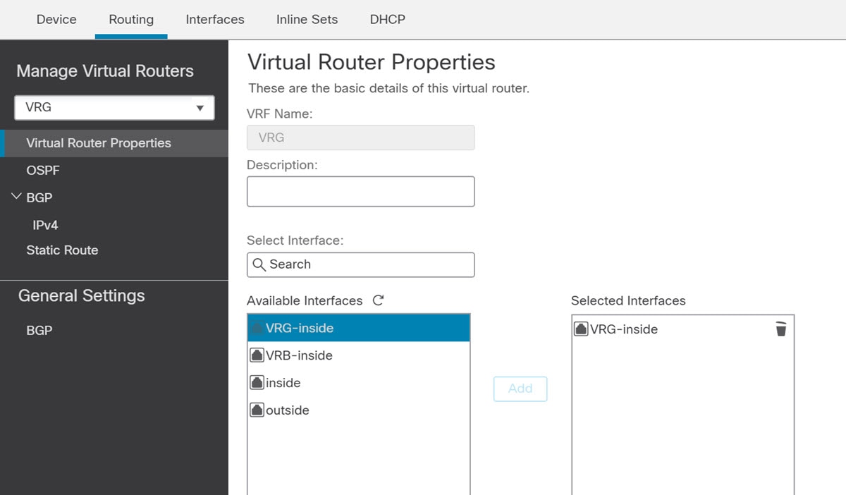
When you create a virtual router, you assign interfaces to the router. You can assign a given interface to one, and only one, virtual router. You would then define static routes, and configure routing protocols such as OSPF or BGP, for each virtual router. You would also configure separate routing processes over your entire network, so that routing tables on all participating devices are using the same per-virtual-router routing process and tables. Using virtual routers, you create logically-separated networks over the same physical network to ensure the privacy of the traffic that runs through each virtual router.
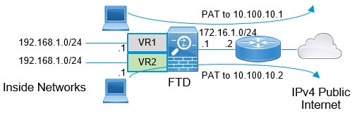
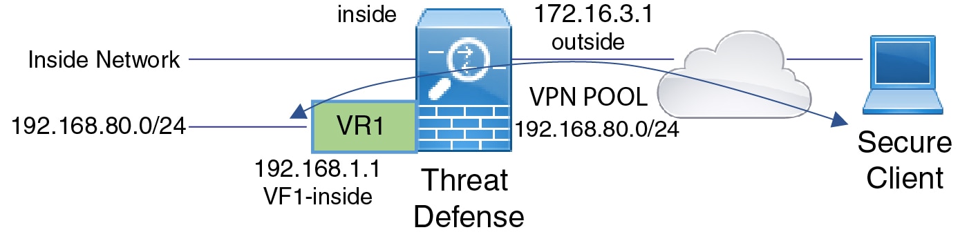
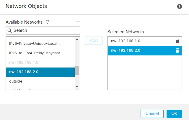
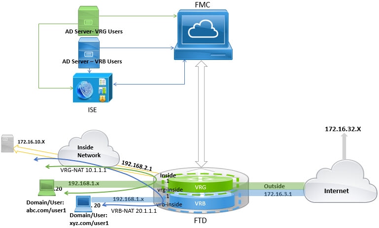
Because the routing tables are separate, you can use the same, or overlapping, address spaces across the virtual routers. For example, you could use the 192.168.1.0/24 address space for two separate virtual routers, supported by two separate physical interfaces.
Note that there are separate management and data routing tables per virtual router. For example, if you assign a management-only interface to a virtual router, then the routing table for that interface is separate from the data interfaces assigned to the virtual router.
Virtual routers and dynamic VTI
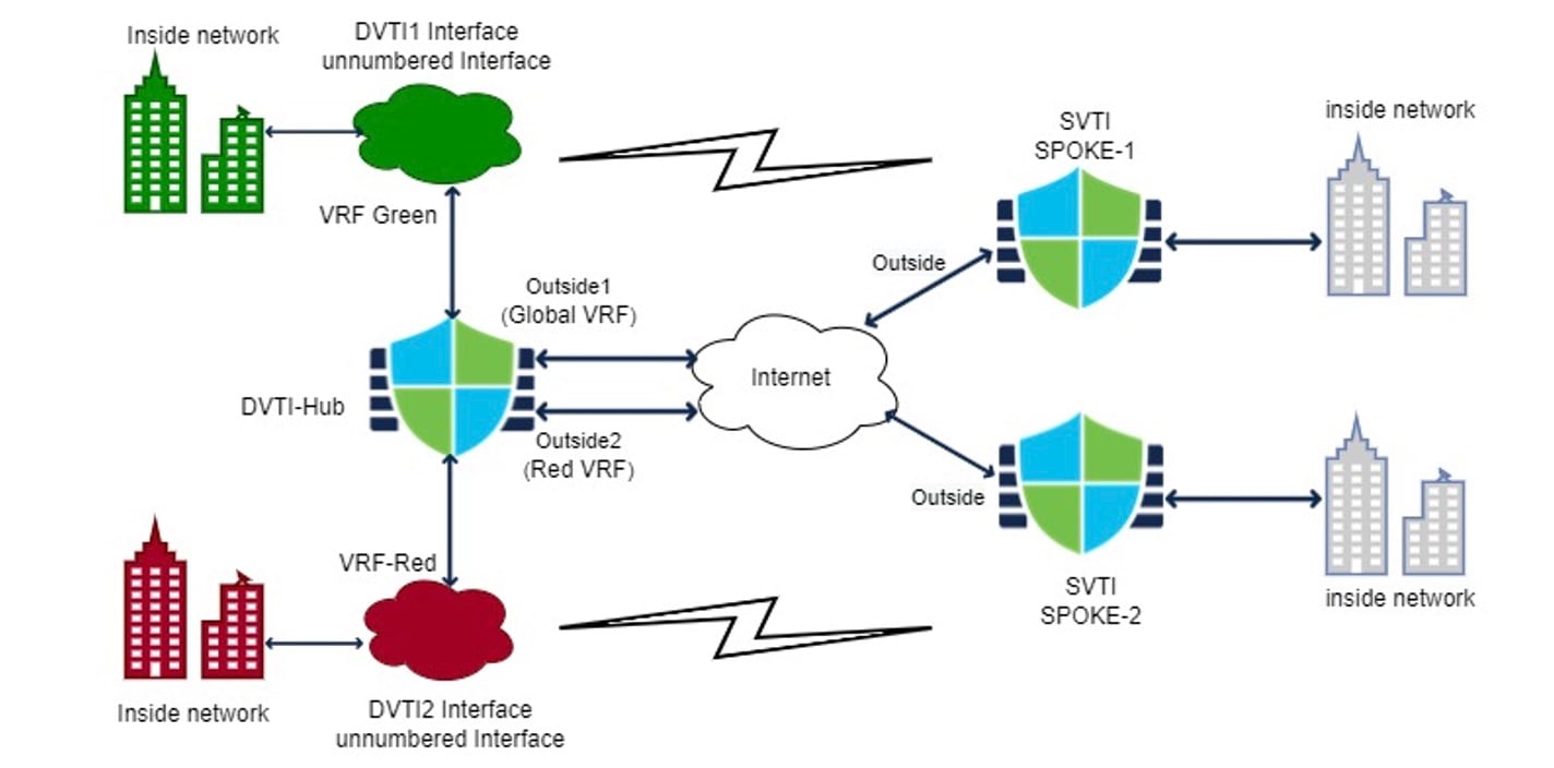
You can create virtual routers, associate dynamic VTIs with these virtual routers, and extend the capabilities of dynamic VTIs in your network. You can associate dynamic VTIs either with global or user-defined virtual routers. You can assign a dynamic VTI to only one virtual router. For more information, refer to Virtual Routers and Dynamic VTI.
Virtual router applications
Virtual router applications are network implementation scenarios that
-
isolate networks on shared resources through dedicated routing tables
-
enable common security policy management across different departments or networks, and
-
provide shared internet access for different departments or networks.
Global and user-defined virtual routers
This reference provides information about global and user-defined virtual routers, including their characteristics and the features supported by each type.
Global virtual routers
For a device with virtual routing capability, system creates a global virtual router by default. The system assigns all interfaces in your network to the global virtual router. A routed interface can belong to either a user-defined virtual router or a global virtual router. When you upgrade Firewall Threat Defense to a version which has virtual router capability, all its existing routing configuration becomes part of the global virtual router.
User-Defined virtual routers
A user-defined virtual router is the one defined by you. You can create more than one virtual router on a device. However, anytime, an interface can be assigned to only one user-defined virtual router. While some of the device features are supported on user-defined virtual routers, few of the features are supported only on the global virtual routers. User-defined virtual routers support route-based site-to-site VPN (static VTI) (static and dynamic VTI).
Supported features and monitoring policies
You can configure these features on the global virtual router only:
-
OSPFv3
-
RIP
-
EIGRP
-
IS-IS
-
Multicast Routing
-
Policy Based Routing (PBR)
ISIS and PBR are supported through Flex Config in Firewall Management Center (see Predefined FlexConfig objects). Configure only global virtual router interfaces for these features.
DHCP server auto-configuration uses WINS/DNS server that is learned from an interface. This interface can only be a global virtual router interface.
You can configure these features separately for each user-defined virtual router:
-
Static routes and their SLA monitors
-
OSPFv2
-
BGPv4/v6
-
Integrated Routing and Bridging (IRB)
-
SNMP
These features are used by the system when querying or communicating with the remote system (from-the-box traffic). These features use interfaces in the global virtual router only. That means, if you configure an interface for the feature, it must belong to the global virtual router. As a rule, anytime, if the system must look up a route to reach an external server for its own management purposes, it does the route lookup in the global virtual router.
-
DNS server when used to resolve fully qualified names used in access control rules, or for resolving names for the ping command. If you specify any as the interface for a DNS server, the system considers interfaces in the global virtual router only.
-
AAA server or identity realm when used with VPN. You can configure VPN on interfaces in the global virtual router only. Thus, the external AAA servers that are used for VPN, such as Active Directory, must be reachable through an interface in the global virtual router.
Virtual-router-aware policies
Virtual-router-aware policies are security policies that
-
apply to interfaces from a single virtual router only
-
use security zones whose memberships are constrained to interfaces assigned to a specific virtual router, and
-
prevent policies from affecting all interfaces across all virtual routers when that is not desired.
Virtual router policy behavior
When you create a virtual router, the routing table for that virtual router is automatically separated from the global virtual router or any other virtual router. However, security policies are not automatically virtual-router-aware.
For example, if you write an access control rule that applies to "any" source or destination security zone, then the rule will apply to all interfaces across all virtual routers. This might in fact be exactly what you want. For example, all of your customers might want to block access to the same list of objectionable URL categories.
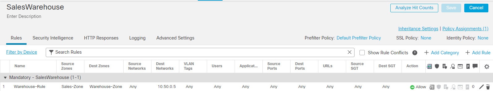
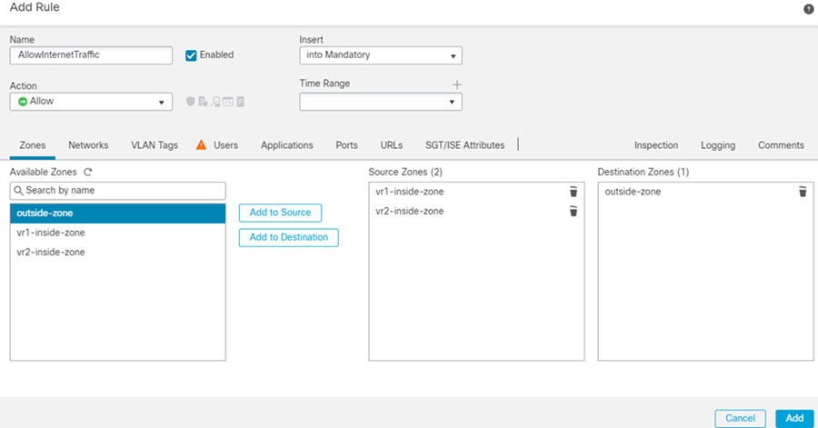
But, if you need to apply a policy to one of the virtual routers but not others, you need to create security zones that contain interfaces from that single virtual router only. Then, use the virtual-router-constrained security zones in the source and destination criteria of the security policy.
By using security zones whose memberships are constrained to the interfaces assigned to a single virtual router, you can write virtual-router-aware rules in these policies:
-
Access control policy.
-
Intrusion and file policies.
-
SSL decryption policy.
-
Identity policy and user-to-IP address mappings. If you use overlapping address spaces in virtual routers, ensure that you create separate realms for each virtual router and apply them correctly in the identity policy rules.
If you use overlapping address spaces in your virtual routers, you should use security zones to ensure that the right policies get applied. For example, if you use the 192.168.1.0/24 address space in two separate virtual routers, an access control rule that simply specifies the 192.168.1.0/24 network will apply to traffic in both virtual routers. If that is not the desired outcome, you can limit the application of the rule by also specifying the source/destination security zones for just one of the virtual routers.
Virtual router interconnection
Virtual router interconnection is a routing mechanism that
-
enables traffic routing between virtual routers through route leaking,
-
supports both manual static routes and dynamic BGP configurations, and
-
allows network segmentation while maintaining controlled inter-segment communication.
Route leaking methods
You can configure the device to route traffic between virtual routers. This process of route leaking can be done manually by setting up static routes or dynamically through BGP settings.
Static route leaking involves manual configuration:
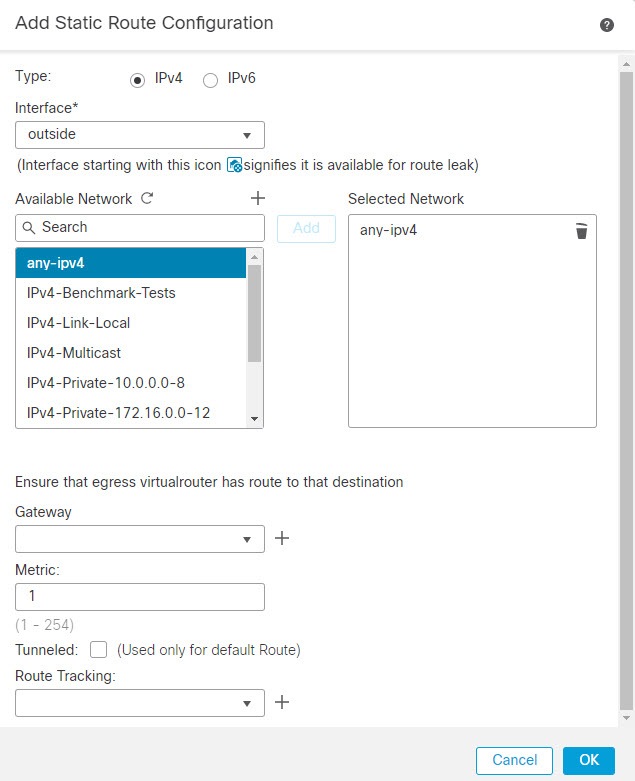
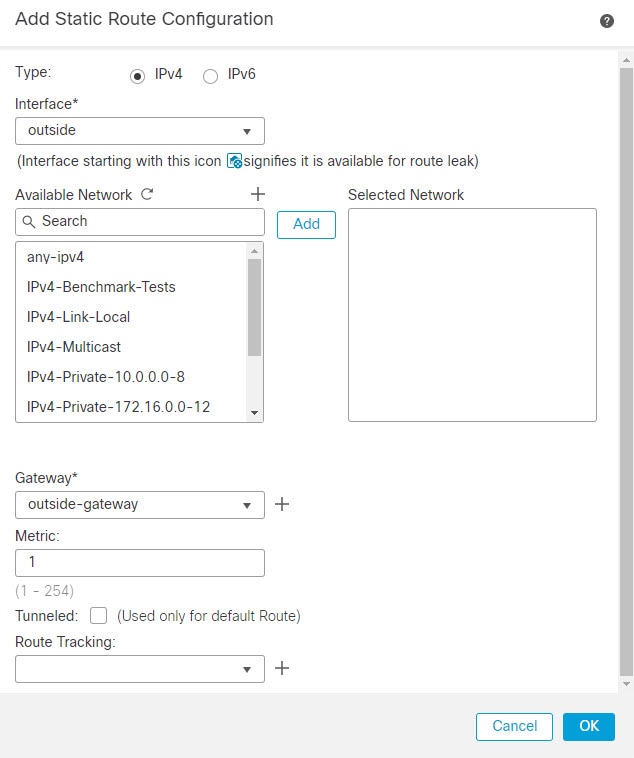
You can configure static routes to route traffic between virtual routers.
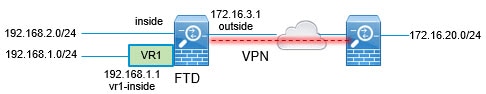
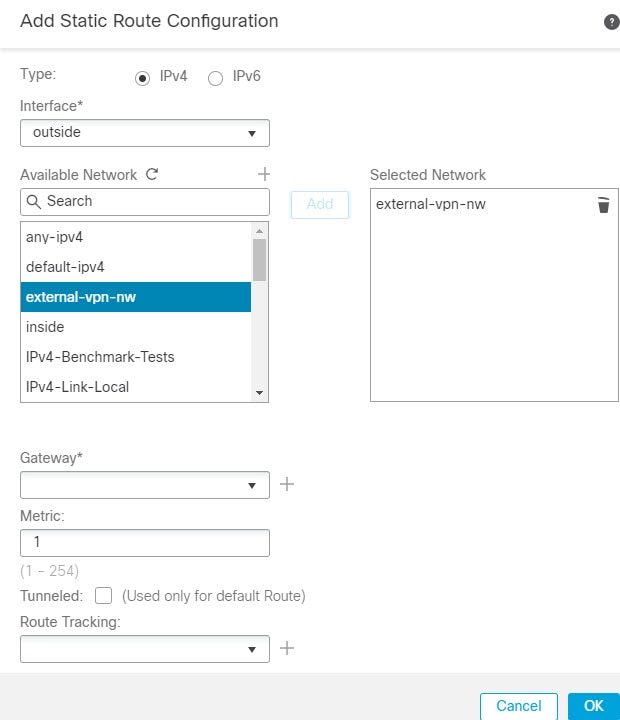
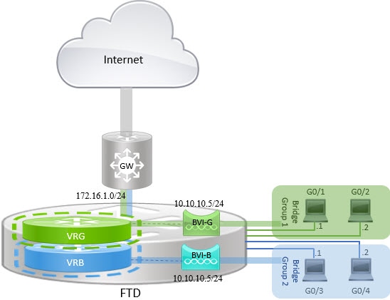
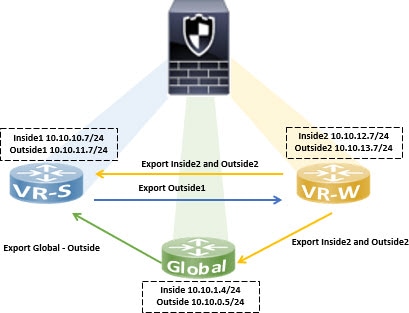
For example, if you have the outside interface in the global virtual router, you can set up static default routes in each of the other virtual routers to send traffic to the outside interface. Then, any traffic that cannot be routed within a given virtual router gets sent to the global router for subsequent routing.
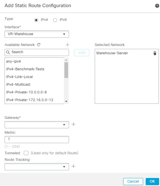
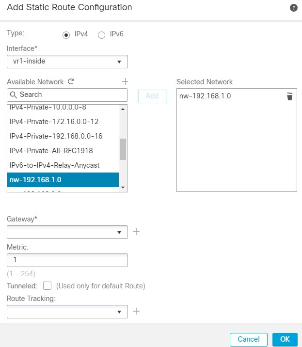
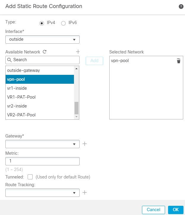
Static routes between virtual routers are known as route leaks, because you are leaking traffic to a different virtual router. When you are leaking routes, say, VR1 routes to VR2, you can initiate connections from VR2 to VR1 only. For traffic to flow from VR1 to VR2, you must configure the reverse route. When you create a static route to an interface in another virtual router, you do not need to specify a gateway address. Simply select the destination interface.
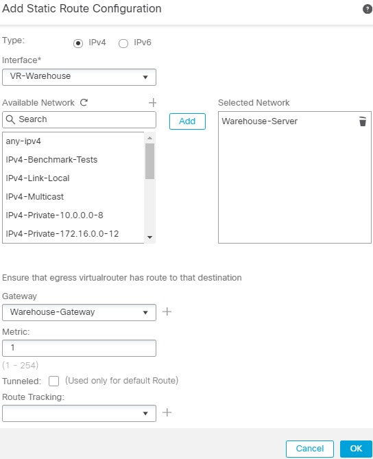
For inter-virtual-router routes, the system does destination interface look-up in the source virtual router. Then, it looks up the MAC address of the next hop in the destination virtual router. Thus, the destination virtual router must have either a dynamic (learned) or static route for the selected interface for the destination address.
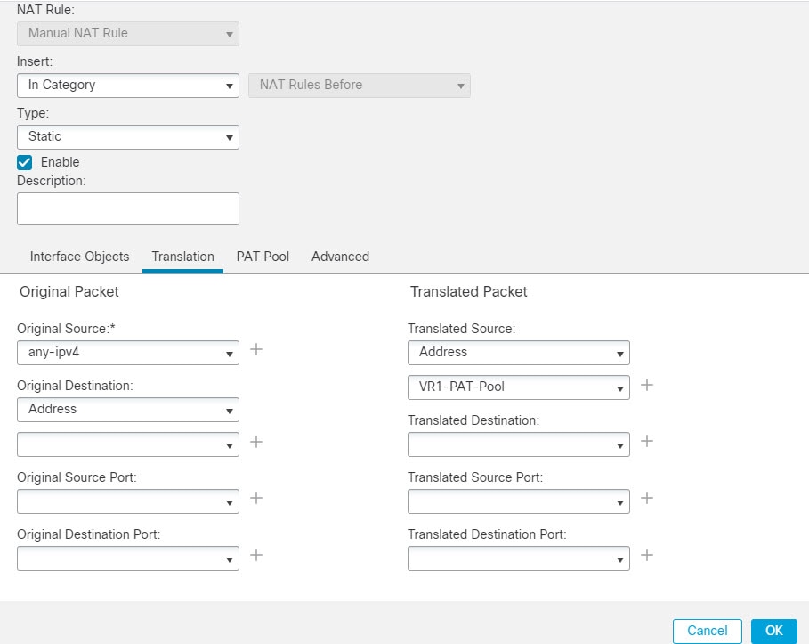
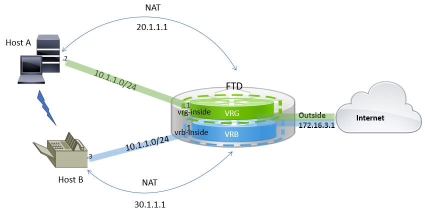
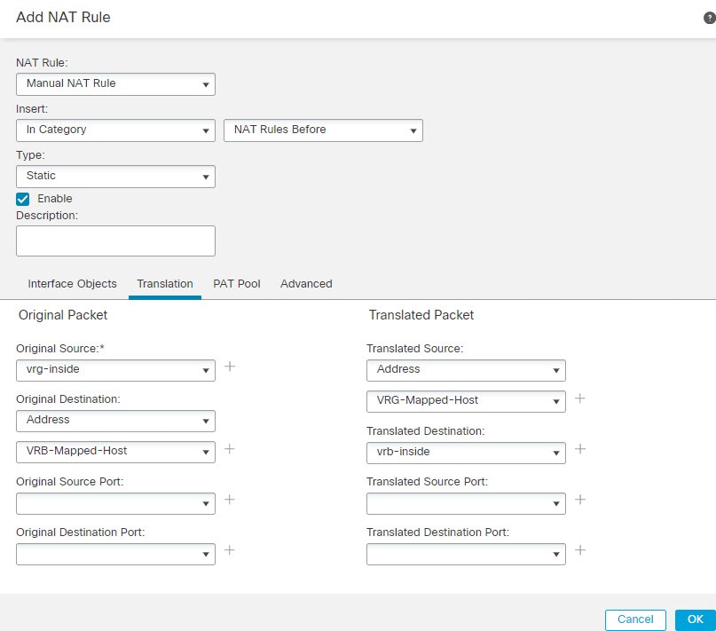
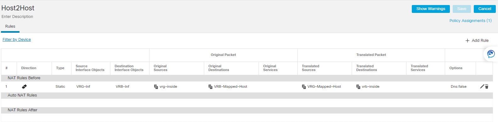
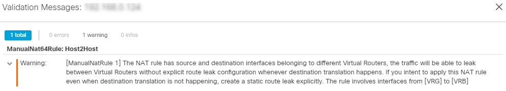
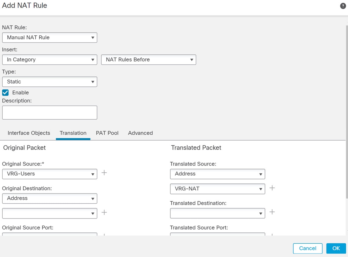
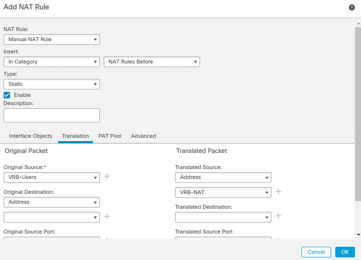
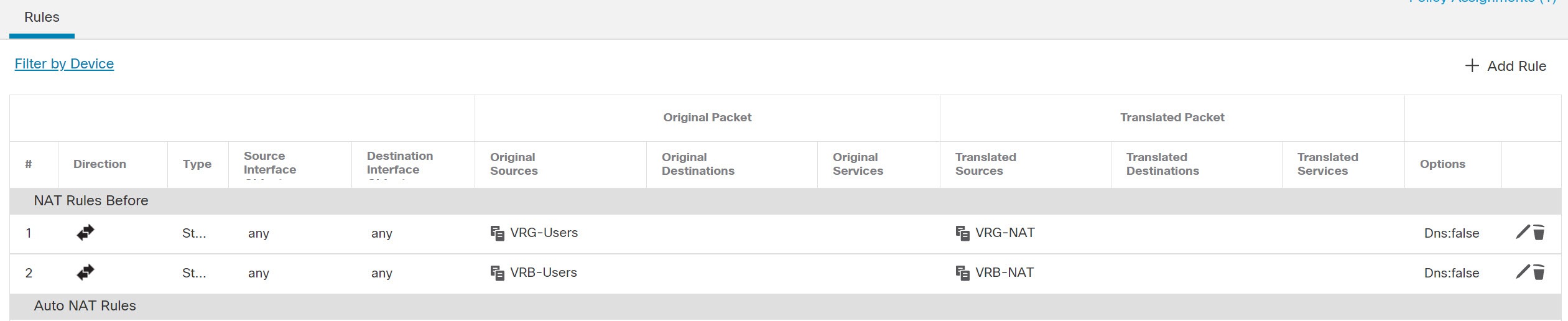
Configuring NAT rules that use source and destination interfaces in different virtual routers can also allow traffic to route between virtual routers. If you do not select the option for NAT to do a route lookup, the rule will simply send traffic out the destination interface with a NATed address whenever destination translation happens. However, the destination virtual router should have a route for the translated destination IP address so that next-hop lookup can succeed.
Though NAT rule leaks traffic from one virtual router to another, to ensure correct routing, we recommend that you configure a static route leak between these virtual routers for the translated traffic. Without the route leak, sometimes the rule may not match the traffic you expect it to match, and the translation may not be applied.
Virtual routing does not support a cascading or chain of route leaks. For example, assume that your Firewall Threat Defense has VR1, VR2, and VR3 virtual routers; VR3 is directly connected to a network - 10.1.1.0/24. Now, assume you configure a route leak in VR1 for network 10.1.1.0/24 through interface in VR2 and in VR2 define a route leak for 10.1.1.0/24 through VR3. This chain of route leaks will not allow traffic to hop from VR1 to VR2 and then exit from VR3. In case of route leaks, the route lookups first determine egress interface from input Virtual Router's routing table and then looks at the output of Virtual Router's routing table for next hop lookup. From both the lookups, egress interface should match. In our example, the egress interfaces will not be the same and hence the traffic does not pass through.
Use static inter VRF route with caution when the destination network is not a direct-connected subnet of the upstream (outgoing) VR. For example, assume two VRs - VR1 and VR2. While VR1 handles the outgoing traffic which gets the default route from its external peer through BGP or any dynamic routing protocol, and VR2 handles the incoming traffic which is configured with static inter VRF default route with VR1 as the next-hop. When VR1 loses the default route from its peer, VR2 will not able to detect that its upstream (outgoing) VR lost the default route and the traffic is still sent toward VR1 which will eventually get dropped without notifications. In this scenario, we recommend that you configure VR2 with dynamic route leak through BGP.
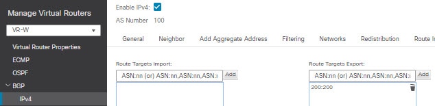
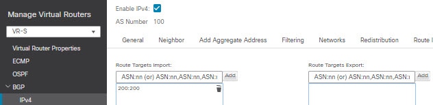
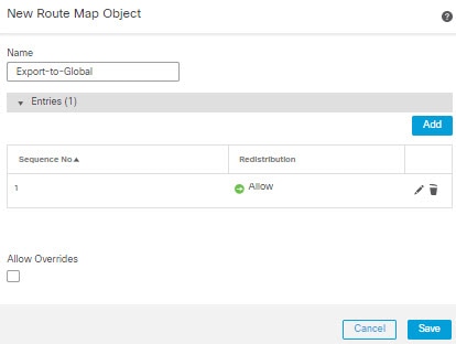
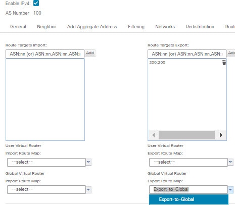
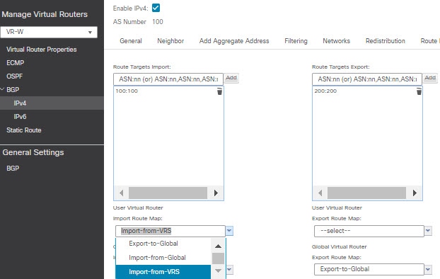
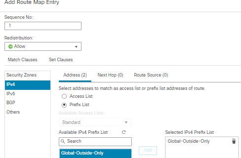
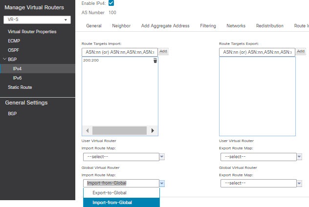
You can implement an inter-virtual-router route leak by exporting routes from a source virtual router (say VR1) to the source BGP table using route target extended community and then importing the same route target extended community from the source BGP table into the destination BGP table, which in turn is used by the destination virtual router (say, VR2). You can use the route maps for filtering the routes. The routes of global virtual router can also be leaked to user-defined virtual routers and vice versa. The BGP inter-virtual-router route leaking supports both ipv4 and ipv6 prefixes.
For details on configuring BGP route leaking, see Configure BGP route import and export.
BGP route leaking guidelines:
-
Ensure that all the routes required for recursion are imported and present in the routing table of the ingress virtual router.
-
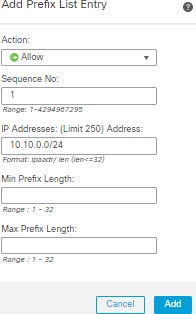
ECMP is supported per virtual router. Hence, do not configure an ECMP across different virtual routers. The overlapping prefixes imported from different virtual routers cannot form an ECMP. That is, when you attempt to import routes with overlapping addresses from two different virtual routers to other virtual routers (a global virtual router or an user-defined virtual router), only one route (as per BGP best path algorithm, the first route that was advertised) is imported to the respective virtual routing table. For example, if a network 10.10.0.0/24, connected to VR1 is advertised through BGP to a global virtual router first, and later another network with the same address 10.10.0.0/24, connected to VR2 is also advertised through BGP to global virtual router, only the VR1 network route is imported to the global virtual routing table.
-
OSPFv3 is not supported on user-defined virtual routers. Hence, do not configure BGPv6 to leak OSPFv3 user-defined virtual routers to global virtual router. However, you can configure BGPv6 to leak OSPFv3 global virtual router routes to user-defined virtual router through redistribution.
-
It is recommended to keep VTI interface, protected internal interfaces (loopback interface if supported for VTI) to be part of same virtual router to prevent the need for route leak.
Best practice for overlapping IP addresses
Virtual router creates multiple instances of routing tables that are independent, thereby, the same or overlapping IP addresses can be used without conflicts. Firewall Threat Defense allows the same network to be part of two or more virtual routers. This involves multiple policies to be applied at the interface or at the virtual router level.
Limitations with overlapping IP addresses
When using an overlapping IP address in multiple virtual routers, to ensure proper application of the policy, you have to modify policies or rules for some of the features. Such features require you to use more specific interface either by splitting existing security zone or using new interface group as the need be.
-
Network Map—Modify the network discovery policy to exclude some overlapping IP segments to ensure that there is no overlapping IP address being mapped.
-
Identity Policy—The identity feed source cannot differentiate among virtual routers; to overcome this limitation, map overlapping address spaces or virtual routers in different realms.
-
Access Policy—Apply rules on specific interfaces to ensure that different policies are applied on overlapping IP segments.
-
Prefilter Policy—Apply rules on specific interfaces to ensure that different policies are applied on overlapping IP segments.
-
QoS/Rate Limit—Apply rules on specific interfaces to ensure that different policies are applied on overlapping IP segments.
-
SSL Policy—Apply rules on specific interfaces to ensure that different policies are applied on overlapping IP segments.
Unsupported features with overlapping IP addresses
These features are not supported with overlapping IP addresses:
-
ISE SGT-based Rule in AC Policy—The static security group tag (SGT) to IP address mappings downloaded from Cisco Identity Services Engine (ISE) are not virtual-router-aware. Set up separate ISE systems per virtual router if you need to create different SGT mappings per virtual router. This is not necessary if you intend to map the same IP addresses to the same SGT number in each virtual router.
-
Overlapping DHCP server pools are not supported across virtual routers.
-
Events and Analytics—Many of the Firewall Management Center analytics are dependent on network map and identity mappings which cannot differentiate if the same IP address belongs to two different end hosts. Hence, these analytics are not accurate when there are overlapping IP segments existing in same device but different virtual routers.
Other than few exceptions, the routing functions and most of the NGFW and IPS capability does not get impacted by the overlapping IP addresses.
Configuring SNMP on user-defined virtual routers
In addition to supporting SNMP on the management interface and Global virtual router data interfaces, Secure Firewall Threat Defense now allows you to configure SNMP host on user-defined virtual routers.
Summary
The key components involved in configuring SNMP on user-defined virtual routers are:
-
Device interfaces: Physical or logical interfaces that need to be configured and enabled
-
Virtual router: User-defined virtual router configured on specific interfaces
-
SNMP hosts: Network management stations that receive SNMP polling and traps
-
Secure Firewall Threat Defense: The target device where configurations are deployed
Workflow
The SNMP configuration on user-defined virtual routers involves these stages:
- Configure device interfaces.
- Configure virtual router on an interface.
-
Configure SNMP hosts on a virtual router interface.

Note
SNMP is not virtual router-aware. Hence, while configuring SNMP server on the user-defined virtual router, ensure that the network address is not an overlapping IP address.
- Deploy configurations to Secure Firewall Threat Defense. On successful deployment, the SNMP polling and traps are sent to the Network Management Station through the virtual router interface.
 )
)


 and click
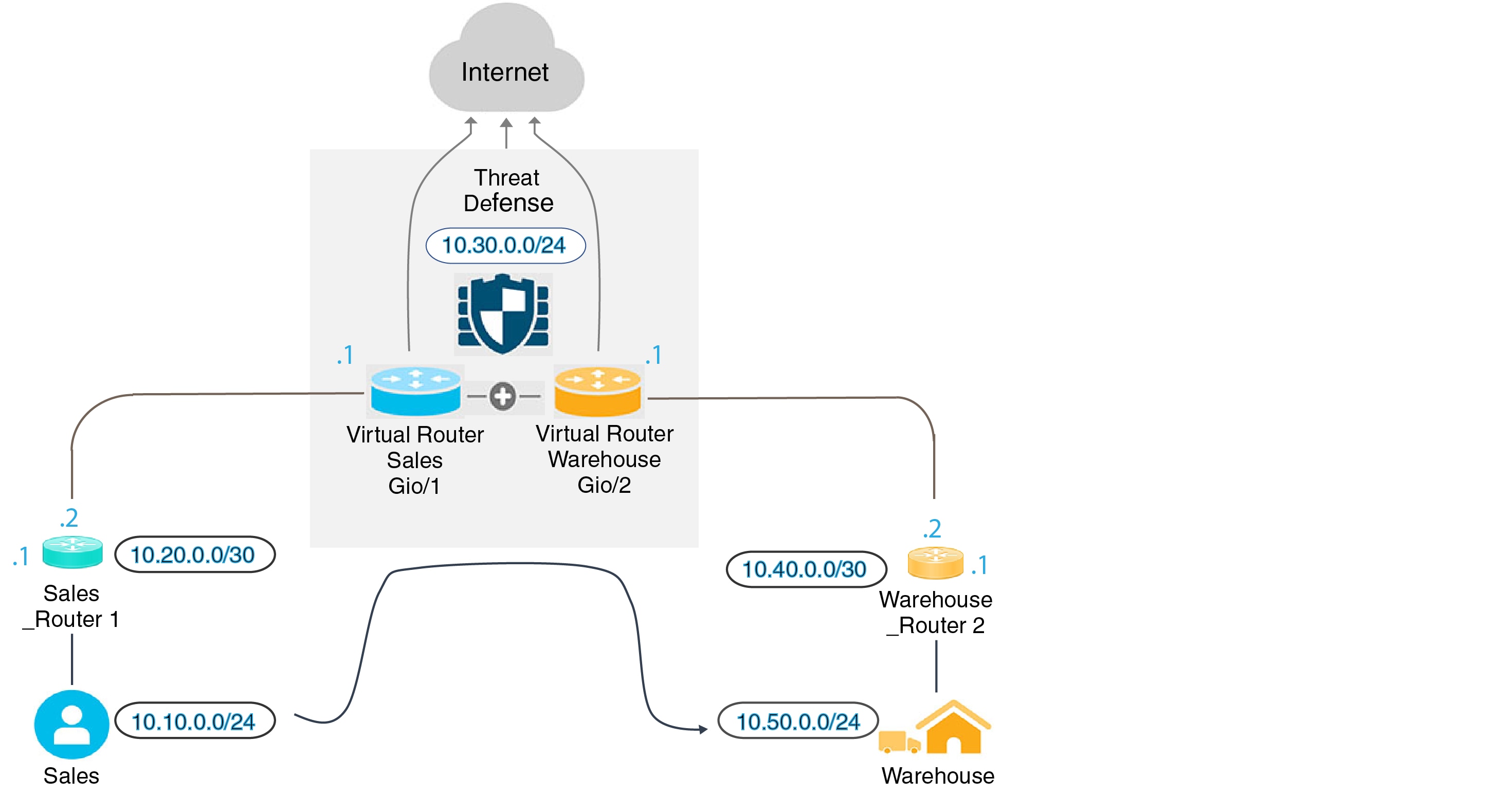


 Feedback