Deploy Firewall Threat Defense Container in Amazon EKS Environment

You can deploy the Firewall Threat Defense container (FTDc) in an Amazon EKS environment.

Prerequisites to Deploy Firewall Threat Defense Container in Amazon EKS Environment

Following are the prerequisites to deploy Firewall Threat Defense container in an Amazon EKS environment:

  • Operating System: Ubuntu, Version - 20.04 LTS (minimum), 22.04 LTS (maximum)

  • Kubernetes Environment:

    • Amazon EKS cluster version - 1.35

    • Managed or self-managed node group with at least one worker node.

    • Multus CNI installed for multi-network support.

  • Kubernetes CNI

    • POD management CNI - AWS VPC CNI

    • FTDc data network CNI - Multus macvlan (passthru mode)

  • Worker Node Requirements:

    • Hugepages configured (2Mi pages)

    • Use SSD/NVMe storage. HDD-based storage is not supported.

    • Data ENIs attached to data subnets.

    • Data ENIs tagged: node.k8s.amazonaws.com/no_manage=true.

    • Source/Destination check disabled on all data ENIs.

    • Worker node labeled with a custom label (for example, ftdc-node=worker1).

EKS Cluster Setup (one-time)

  1. Multus CNI must be installed on the EKS cluster:

    kubectl apply -f https://raw.githubusercontent.com/k8snetworkplumbingwg/multus-cni/master/deployments/multus-daemonset-thick.yml
  2. Tune VPC CNI to prevent it from managing data ENIs and pin a stable pod management IP address:

    kubectl set env daemonset aws-node -n kube-system \
      WARM_ENI_TARGET=0 \
      WARM_IP_TARGET=1 \
      MINIMUM_IP_TARGET=1
  3. Pin a stable management IP address for the FTDc pod: By default, VPC CNI assigns a random secondary IP address from the primary ENI's subnet on each pod restart. To ensure the pod always gets the same management IP address:

    1. Remove all existing secondary IP addresses from the primary ENI:
      aws ec2 unassign-private-ip-addresses --network-interface-id <primary-eni-id> \
        --private-ip-addresses <ip1> <ip2> ...
    2. Assign a single specific IP address (for example, 10.0.1.10):
      aws ec2 assign-private-ip-addresses --network-interface-id <primary-eni-id> \
        --private-ip-addresses 10.0.1.10

    Since 10.0.1.10 is the only secondary IP address in the pool, VPC CNI will always assign it to the pod. The IP address stays on the ENI across pod restarts — VPC CNI only manages the pod-to-IP address mapping, not the ENI-level assignment.


    Note


    On node replacement, the new node has a different primary ENI. You must re-assign 10.0.1.10 on the new ENI.


  4. Label the worker nodes:

    kubectl label node <node-name> ftdc-node=worker1

AWS Infrastructure Requirements

  1. Create the EKS node group in the management subnet (10.0.1.x) so the primary ENI is in the mgmt network.

  2. Attach data ENIs from other subnets (must be same AZ as the node):

    aws ec2 attach-network-interface --instance-id <instance-id> \
      --network-interface-id <eni-id> --device-index <index>
  3. Tag data ENIs with no_manage to prevent VPC CNI from allocating secondary IP addresses or detaching them:

    aws ec2 create-tags --resources <eni-inside> <eni-diag> <eni-outside> \
      --tags Key=node.k8s.amazonaws.com/no_manage,Value=true

    Without this tag, VPC CNI will treat data ENIs as its own warm ENIs and may detach or delete them during pod lifecycle events.

  4. Disable Source/Destination check on data ENIs (required for FTDc to route/inspect traffic):

    aws ec2 modify-network-interface-attribute --network-interface-id <eni-id> \
      --no-source-dest-check

    This must be done for each data ENI. Without this, AWS will drop any traffic where the source or destination IP address does not match the ENI's assigned IP address.

  5. Assign secondary IP addresses on data ENIs for FTDc pod data interfaces:

    FTDc data interfaces (configured via DHCP or statically inside FTDc) need IP addresses that are registered on the corresponding ENI to be VPC-routable. Assign a secondary IP address to each data ENI:

    
    aws ec2 assign-private-ip-addresses --network-interface-id <eni-diag-id>    --private-ip-addresses 10.0.2.10
    aws ec2 assign-private-ip-addresses --network-interface-id <eni-inside-id>  --private-ip-addresses 10.0.3.10
    aws ec2 assign-private-ip-addresses --network-interface-id <eni-outside-id> --private-ip-addresses 10.0.4.10
    • DHCP from inside the pod will assign the ENI's primary IP address (for example, 10.0.2.101)

    • To use a specific IP address (for example, x.x.x.10), configure it statically inside FTDc — AWS DHCP only hands out the primary IP address

    • Any IP address not registered on the ENI will be silently dropped by the VPC router

  6. ECR access must be configured via IAM instance profile or node role.

Additional Requirements

  • Helm: Version 3.8 or later for deploying FTDc using Helm charts (YAML-based Infrastructure-as-Code)

  • Firewall Threat Defense Container (FTDc) image available in an accessible registry

  • Management Center accessible from the cluster
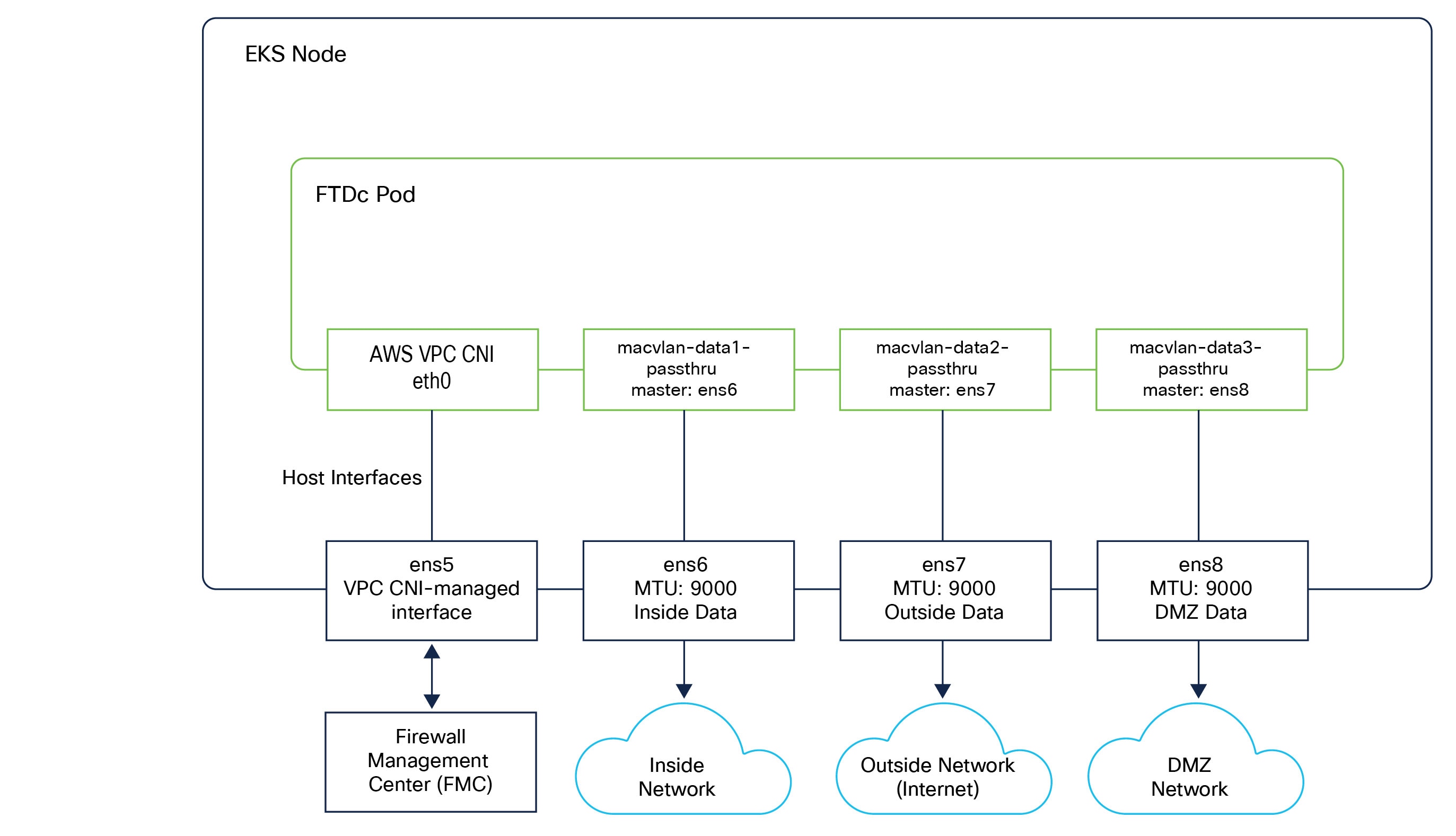
Sample Topology to Deploy Firewall Threat Defense Container in Amazon EKS Environment

The diagram shows an FTDc pod deployed on an EKS node, connected to multiple network segments using AWS VPC and macvlan CNI.

  • The primary interface (ens5) is managed by the AWS VPC CNI and is used for pod communication with the Management Center.

  • The inside interface connects to the inside endpoint network.

  • The outside interface connects to the outside endpoint network.

Deploy Firewall Threat Defense Container in Amazon EKS Environment

Follow the procedure to deploy Firewall Threat Defense container (FTDc) in an Amazon EKS environment.

Procedure


Step 1

Set up the requirements mentioned in the Prerequisites.

Step 2

Clone the FTDc repository to the local folder.

git clone <repository-URL>

Step 3

Navigate to the Helm chart directory.

cd Helm_charts/ftdc-helm

Step 4

Deploy FTDc.

You can deploy FTDc using either the default configuration or a custom values file.

  • Using Helm with default configuration:

    helm install ftdc . -n <namespace>

  • Using Helm with a custom values file:

    helm install ftdc . -f my-values.yaml -n <namespace>

Note


Namespace should be created before using it in the helm install command.

Step 5

Deploy FTDc using Helm with additional parameters.

helm install ftdc . \
  --set ftdc.repository=<account>.dkr.ecr.<region>.amazonaws.com/ftdc:<tag> \
  --set ftdc.app_name=ftdc \
  --set ftdc.cpus=4 \
  --set ftdc.memory=8192 \
  --set ftdc.hugepages=auto \
  --set worker_nodes.cni.type=macvlan \
  --set worker_nodes.persistence.lina.enabled=true \
  --set worker_nodes.persistence.lina.hostPath=/home/ubuntu/lina-path \
  --set worker_nodes.persistence.ngfw.enabled=true \
  --set worker_nodes.persistence.ngfw.hostPath=/home/ubuntu/ngfw-path \
  --set worker_node1.label=worker1 \
  -n default

Step 6

Update the configuration parameters in the Helm chart.

See the configuration parameters in the following tables:

Table 1. FTDc container settings

Parameter

Description

Default Value

Required

ftdc.repository

FTDc container image repository

localhost:5000/ftdc_10.0.0.143

Yes

ftdc.app_name

Application name for deployment

ftdc

Yes

ftdc.cpus

Number of CPUs allocated to FTDc

4

Yes

ftdc.memory

Memory in MB allocated to FTDc

8192

Yes

ftdc.shmSize

Shared memory (/dev/shm) size

2Gi

No

ftdc.hugepages

Hugepages allocation

auto

No

replicas

Number of pod replicas

1

No

namespace

FTD container name space for deployment

default

No

Supported CPU and memory configurations:

The following CPU and memory configurations are supported for FTDc deployment in Kubernetes environments. These configurations align with supported performance tiers.

  • FTDv5 – 4 vCPU, 8 GB RAM

  • FTDv10 – 4 vCPU, 8 GB RAM

  • FTDv20 – 4 vCPU, 8 GB RAM

  • FTDv30 – 8 vCPU, 16 GB RAM

  • FTDv50 – 12 vCPU, 24 GB RAM

  • FTDv100 – 16 vCPU, 32 GB RAM

Hugepages configuration:

The ftdc.hugepages parameter supports two modes:

  1. Auto-calculation ("auto"): Calculates hugepages based on CPUs and interfaces:

    Formula: (CPUs128) + (numInterfaces64) Mi, rounded upto nearest 256 Mi.

    Example: 4 CPUs + 3 interfaces = (4×128) + (3×64) = 704Mi → rounded to 768Mi

  2. Fixed value: Specify exact size like "512Mi", "1Gi", "2Gi"

Table 2. Worker Node Configuration

Parameter

Description

Default Value

Required

worker_node1.label Kubernetes label for the worker node ftdc-node=worker1 Yes
Table 3. CNI Configuration

Parameter

Description

Default Value

worker_nodes.cni.type CNI type: macvlan macvlan

Macvlan Configuration:

Use this configuration when worker_nodes.cni.type is set to macvlan.

worker_nodes: 
  cni: 
    type: "macvlan" 
    macvlan: 
  networks: 
    - name: "macvlan-data1-passthrough" # NetworkAttachmentDefinition name 
      interface: "ens6"          # Host interface 
    - name: "macvlan-data2-passthrough" 
      interface: "ens7" 
    - name: "macvlan-data3-passthrough" 
      interface: "ens8"

The Helm chart automatically creates NetworkAttachmentDefinition resources for each network.

  • Generated interface-config:

    [interface0] 
      iface_id = net1; 
      uio_driver = afpacket;
    [interface1] 
      iface_id = net2; 
      uio_driver = afpacket;
    [interface2] 
      iface_id = net3; 
      uio_driver = afpacket;
    

Persistent storage:

Persistent volumes retain FTDc data across restarts.

Table 4. Lina storage (default) parameters and values

Parameter

Description

Default Value

worker_nodes.persistence.lina.storageClass Storage class name lina-storage
worker_nodes.persistence.lina.size Volume size 1Gi
worker_nodes.persistence.lina.hostPath Host path on workernodes /home/ubuntu/lina-path
Table 5. NGFW storage (optional) parameters and values

Parameter

Description

Default Value

worker_nodes.persistence.ngfw.storageClass Storage class name NGFW-storage
worker_nodes.persistence.ngfw.size Volume size 5Gi
worker_nodes.persistence.ngfw.hostPath Host path on workernodes /home/ubuntu/ngfw-path

Step 7

Configure Day-0 parameters in the day0.json file.

The day0.json file provides initial bootstrap configuration for FTDc.

Default Configuration (day0.json):

{ 
"EULA": "accept", 
"Hostname": "cisco-ftdc", 
"AdminPassword": "<PASSWORD>", 
"FirewallMode": "routed", 
"DNS1": "<enter-ip-address>", 
"Diagnostic": "OFF", 
"IPv4Mode": "DHCP", 
"IPv4Addr": "", 
"IPv4Mask": "", 
"IPv4Gw": "", 
"FmcIp": "DONTRESOLVE", 
"FmcRegKey": "docker",  
"FmcNatId": "docker"
}
Table 6. Day-0 parameters Configuration

Field

Description

EULA Accept EULA (accept)
Hostname FTDc hostname
AdminPassword Admin password for FTDc
FirewallMode routed or transparent
DNS1 Primary DNS server
Diagnostic Diagnostic interface (ON/OFF)
IPv4Mode DHCP or Manual
IPv4Addr Static IP (if Manual mode)
IPv4Mask Subnet mask (if Manual mode)
IPv4Gw Gateway (if Manual mode)
FmcIp Management Center IP or DONTRESOLVE
FmcRegKey Registration key for Management Center
FmcNatId NAT ID for Management Center registration

Deployment Examples:

Example: Basic Deployment with Macvlan

# values-basic.yaml
ftdc:
  repository: "myregistry.example.com/ftdc:7.4"
  app_name: "ftdc"
  cpus: 4
  memory: 8192
  shmSize: "2Gi"
  hugepages: "auto"

worker_nodes:
  cni:
    type: "macvlan"
    macvlan:
      networks:
        - name: "macvlan-inside"
          interface: "eth1"
        - name: "macvlan-outside"
          interface: "eth2"
  persistence:
    lina:
      enabled: true
      storageClass: "lina-storage"
      size: "1Gi"
      hostPath: "/data/ftdc/lina" 
      accessMode: "ReadWriteMany"

worker_node1:
  label: "worker1"

bash
helm install ftdc . -f values-basic.yaml

Verify and Access Firewall Threat Defense Container in Amazon EKS Environment

Verify deployment status:

  • Check all resources.

    kubectl get all -l app=FTDC

  • Check pods.

    kubectl get pods -o wide

  • Check service.

    kubectl get svc

  • Check persistent volumes.

    kubectl get pv,pvc

  • Check NetworkAttachmentDefinitions (for macvlan).

    kubectl get net-attach-def

Verify FTDc is running
  • Check pod logs.

    kubectl logs -f <ftdc-pod-name>

  • Check lina process (readiness probe).

    kubectl exec -it <ftdc-pod-name> -- pgrep -x lina

  • Check readiness file.

    kubectl exec -it <ftdc-pod-name> -- cat /tmp/lina_ready

  • Access FTDc CLI.

    kubectl exec -it <ftdc-pod-name> -- /bin/bash

Managing Inter-Namespace Traffic in Amazon EKS Environment

FTDc facilitates secure inter-namespace communication through a combination of dynamic discovery and traffic redirection.

Dynamic discovery and object mapping

FTDc utilizes a controller that monitors the Kubernetes environment for changes in pod status.

  • Dynamic objects: When a pod is created or terminated in a specific namespace, the controller automatically updates the corresponding dynamic object on the Management Center Virtual.

  • IP address mapping: The Management Center Virtual continuously tracks the IP addresses associated with these namespaces. Because these objects are dynamic, firewall policies remain consistent regardless of pod scaling, eliminating the need for manual rule updates.

Traffic redirection

  • To ensure inspection, network traffic must be directed through the FTDc instance.

    • Routing/CNI configuration: The cluster’s Container Network Interface (CNI) or routing tables are configured to route inter-namespace traffic through the FTDc.

    • Transparent inspection: The FTDc acts as a transparent gateway. Traffic between a frontend pod and a backend pod is intercepted by the FTDc rather than being routed directly.