Deploy the Firewall Threat Defense Virtual Unlimited

Overview

From Secure Firewall version 10.0, Firewall Threat Defense Virtual supports a new performance tier license - Firewall Threat Defense Virtual Unlimited (FTDvU). FTDvU supports up to 64 vCPUs.

From version 10.0, you can use the FTDvU license for Firewall Threat Defense Virtual deployments on KVM and VMware.

From version 10.1.0, you can use the FTDvU license for Firewall Threat Defense Virtual deployment on AWS.

Licensing

Firewall Threat Defense Virtual supports performance-tier licensing. From Version 10.0, a new performance tier license Firewall Threat Defense Virtual Unlimited (FTDvU) is introduced. FTDvU supports deployments with up to 64 vCPUs and 128 GB memory.

For more information about licensing and performance tiers, see the Licenses chapter in the Cisco Secure Firewall Management Center Administration Guide.

Table 1. Firewall Threat Defense Virtual Unlimited License Entitlements

Performance Tier

Device Specifications (vCPU/RAM)

RA VPN Session Limit

Supported platforms

FTDv - Unlimited (FTDvU)

32 vCPU/64 GB

20,000

KVM, VMware, AWS

FTDv - Unlimited (FTDvU)

64 vCPU/128 GB

32,000

KVM, VMware, AWS

Deploy the Firewall Threat Defense Virtual Unlimited on KVM

From Secure Firewall version 10.0, you can deploy Firewall Threat Defense Virtual Unlimited (FTDvU) on KVM.

Prerequisites

Hardware Requirements

  • Cisco UCS M7, M8 servers, or later.

  • x86-based processors (64 cores per socket or higher recommended).

  • 100 Gigabit Ethernet NICs - Intel E810 series or NVIDIA/Mellanox ConnectX-6 card.

CPU Requirements

32/64 vCPUs

Memory (RAM)

Minimum of 64 GB RAM for FTDvU 32-core deployments

Minimum of 128 GB RAM for FTDvU 64-core deployments

See the Cisco Secure Firewall Threat Defense Compatibility Guide for the most current information about hypervisor support for the Firewall Threat Defense Virtual.

For more details on generic system requirements, supported platforms, and hardware guidelines, see the System Requirements section in the Deploy the Firewall Threat Defense Virtual on KVM chapter.

Guidelines and Limitations

Ensure that you read the generic guidelines and limitations for deploying Firewall Threat Defense Virtual on KVM.

NUMA Optimization Guidelines for ASAvU

  • Always enforce Single-NUMA placement. Cross-socket memory access introduces significant latency and throughput penalties.

  • Ensure all vCPUs are pinned to a single physical NUMA node. Avoid vCPU/memory pinning across NUMA boundaries to maintain strict memory locality.

Prepare the Day-0 Configuration File

To prepare the Day-0 configuration file used during deployment, see the Prepare the Day-0 Configuration File section in the Deploy the Firewall Threat Defense Virtual on KVM chapter.

Deploy the Firewall Threat Defense Virtual Unlimited using a Deployment Script

Use a virt-install based deployment script to launch the Firewall Threat Defense Virtual Unlimited.

Be aware that you can optimize performance by selecting the best guest caching mode for your environment. The cache mode in use will affect whether data loss occurs, and the cache mode can also affect disk performance.

Each KVM guest disk interface can have one of the following cache modes specified: writethrough, writeback, none, directsync, or unsafe. writethrough provides read caching. writeback provides read and write caching. directsync bypasses the host page cache. unsafe may cache all content and ignore flush requests from the guest.

  • A cache=writethrough will help reduce file corruption on KVM guest machines when the host experiences abrupt losses of power. We recommend that you use writethrough mode.

  • However, cache=writethrough can also affect disk performance due to more disk I/O writes than cache=none.

  • If you remove the cache parameter on the --disk option, the default is writethrough.

  • Not specifying a cache option may also significantly reduce the time required for the VM creation. This is due to the fact that some older RAID controllers have poor disk caching capability. Hence, disabling disk caching (cache=none) and thus defaulting to writethrough, helps ensure data integrity.

  • Starting with version 6.4, the Firewall Threat Defense Virtual deploys with adjustable vCPU and memory resources. Prior to version 6.4, the Firewall Threat Defense Virtual deployed as a fixed configuration 4vCPU/8GB device. See the following table for supported values for the --vcpus and --ram parameters for each Firewall Threat Defense Virtual platform size.

Table 2. Supported vCPU and Memory Parameters for virt-install

--vcpus

--ram

Firewall Threat Defense Virtual Unlimited Platform Size

32

65536 (64 GB)

32 vCPU/ 64 GB (FTDv Unlimited)

64

131072 (128 GB)

64 vCPU / 128 GB (FTDv Unlimited)

Procedure


Step 1

Create a virt-install script called “virt_install_ftdv.sh”.

The name of the Firewall Threat Defense Virtual VM must be unique across all other virtual machines (VMs) on this KVM host. The Firewall Threat Defense Virtual can support up to 10 network interfaces. This example uses four interfaces. The virtual NIC must be VirtIO.

For Version 10.0 and later, the diagnostic interface is optional. The Firewall Threat Defense Virtual can be configured with minimum three interfaces when the diagnostic interface is disabled (one management and two data interfaces). If the diagnostic interface is enabled, a minimum of four interfaces is required (one management interface, one diagnostic interface and two data interfaces).

For more information about the diagnostic interface removal starting in Firewall Threat Defense Virtual version 10.0, see the Diagnostic Interface Removal section.

The default configuration for the Firewall Threat Defense Virtual assumes that you put the management interface, diagnostic interface, and inside interface on the same subnet. The interface-to-network assignments must be ordered as follows:

  • Diagnostic:ON

    • (1) Management interface (required)

    • (2) Reserved for internal use (required)

    • (3) Outside interface (required)

    • (4) Inside interface (required)

    • (5-10) Data interfaces — 3 required, up to 3 additional interfaces allowed (total of 6 data interfaces)

  • Diagnostic:OFF

    • (1) Management interface (required)

    • (2) Outside interface (required)

    • (3) Inside interface (required)

    • (4-10) Data interfaces — 3 required, up to 4 additional interfaces allowed (total of 7 data interfaces)

For Secure Boot Configuration: Use virt-install command with specific parameters.

virt-install \ 
  --connect=qemu:///system \ 
  --network bridge:br1556,model=virtio\ 
  --network bridge:br-in,model=virtio\ 
  --network bridge:br-out,model=virtio\ 
  --name=<prefix>-vm-ftdv \ 
  --cpu host \ 
  --arch=x86_64 \ 
  --vcpus=32 \ 
  --ram=65536 \ 
  --os-type=linux \ 
  --os-variant=generic \ 
  --virt-type=kvm \ 
  --import \ 
  --watchdog i6300esb,action=reset \
  --disk path=<path to qcow2 file>,format=qcow2,device=disk,bus=virtio,cache=none \ 
  --disk path=<path to day0.iso file>,format=iso,device=cdrom,bus=sata \ 
  --console pty,target_type=serial \ 
  --serial tcp,host=127.0.0.1:<port>,mode=bind,protocol=telnet \
  --boot firmware=efi,loader_secure=yes \ 
  --machine q35 \   
  --features smm.state=on \ 
  --force 

Note


Machine type must be q35 and SMM (System Management Mode) must be ON for Secure Boot.

VM Management:

Note


To delete a VM, use the following command:

virsh undefine <vm-name> --nvram

Step 2

Run the virt_install script:

Note


Inline traffic is not supported, as promiscuous mode can not be enabled for the SRIOV interfaces.

Example:

/usr/bin/virt_install_ftdv.sh

Starting install...
Creating domain...

A window appears displaying the console of the VM. You can see that the VM is booting. It takes a few minutes for the VM to boot. Once the VM stops booting, you can issue CLI commands from the console screen.

Important


During registration of Firewall Threat Defense Virtual to the Management Center, select the FTDvU - Unlimited performance tier from the drop-down list to apply the FTDvU license tier.


Launch Using a Graphical User Interface (GUI)

There are a several open-source options available to manage KVM virtual machines using a GUI. The following procedure uses virt-manager, also known as Virtual Machine Manager, to launch the Firewall Threat Defense Virtual. virt-manager is a graphical tool for creating and managing guest virtual machines.


Note


KVM can emulate a number of different CPU types. For your VM, you typically should select a processor type which closely matches the CPU of the host system, as it means that the host CPU features (also called CPU flags) will be available in your VMs. You should set the CPU type to host in which case the VM will have exactly the same CPU flags as your host system.


Procedure


Step 1

Start virt-manager (Applications > System Tools > Virtual Machine Manager).

You may be asked to select the hypervisor and/or enter your root password.

Step 2

Click the button in the top left corner to open the New VM wizard.

Step 3

Enter the virtual machine details:

  1. For the operating system, select Import existing disk image.

    This method allows you to import a disk image (containing a pre-installed, bootable operating system) to it.

  2. Click Forward to continue.

Step 4

Load the disk image:

  1. Click Browse... to select the image file.

  2. Choose Generic for the OS type.

  3. Click Forward to continue.

Step 5

Configure the memory and CPU options:

Important


The Firewall Threat Defense Virtual supports performance-tiered licensing that provides different throughput levels and VPN connection limits based on deployment requirements.

See the following table for supported performance tiers and values for the --vcpus and --ram parameters for each Firewall Threat Defense Virtual platform.

Table 3. Supported vCPU and Memory Parameters for Virtual Machine Manager

CPUs

Firewall Threat Defense Virtual Platform Size

32

32 vCPU / 64 GB (FTDv Unlimited)

64

64 vCPU / 128 GB (FTDv Unlimited)

  1. Set the Memory (RAM) parameter for your Firewall Threat Defense Virtual platform size.

  2. Set the corresponding CPUs parameter for the Firewall Threat Defense Virtual platform size.

  3. Click Forward to continue.

Step 6

Check the Customize configuration before install box, specify a Name, then click Finish.

Doing so opens another wizard that allows you to add, remove, and configure the virtual machine's hardware settings.

Step 7

Modify the CPU configuration:

From the left panel, select Processor, then select Configuration > Copy host CPU configuration.

This applies the physical host's CPU model and configuration to your VM.

Step 8

Configure the Virtual Disk:

  1. From the left panel, select Disk 1.

  2. Select Advanced options.

  3. Set the Disk bus to Virtio.

  4. Set the Storage format to qcow2.

Step 9

Configure a serial console:

  1. From the left panel, select Console.

  2. Select Remove to remove the default console.

  3. Click Add Hardware to add a serial device.

  4. For Device Type, select TCP net console (tcp).

  5. For Mode, select Server mode (bind).

  6. For Host, enter 0.0.0.0 for the IP address, then enter a unique Port number.

  7. Check the Use Telnet box.

  8. Configure device parameters.

Step 10

Configure a watchdog device to automatically trigger some action when the KVM guest hangs or crashes:

  1. Click Add Hardware to add a watchdog device.

  2. For Model, select default.

  3. For Action, select Forcefully reset the guest.

Step 11

Configure virtual network interfaces.

Click Add Hardware to add an interface, then choose macvtap or specify a shared device name (use a bridge name).

For Version 10.0 and later, the diagnostic interface is optional. The Firewall Threat Defense Virtual can be configured with minimum three interfaces when the diagnostic interface is disabled (one management and two data interfaces). If the diagnostic interface is enabled, a minimum of four interfaces is required (one management interface, one diagnostic interface and two data interfaces).

For more information about the diagnostic interface removal starting in Firewall Threat Defense Virtual version 10.0, see the Diagnostic Interface Removal section.

  • Diagnostic:ON

    • vnic0—Management interface (required)

    • vnic1—Reserved for internal use (required)

    • vnic2— Outside interface (required)

    • vnic3—Inside interface (required)

    • vnic4-vnic9—Data interfaces (optional)

    Make sure vnic0 and vnic3 are mapped to the same subnet.

  • Diagnostic:OFF

    • vnic0—Management interface (required)

    • vnic1—Outside interface (required)

    • vnic2—Inside interface (required)

    • vnic3-vnic9—Data interfaces (optional)

    Make sure vnic0 and vnic2 are mapped to the same subnet.

Step 12

If deploying using a Day 0 configuration file, create a virtual CD-ROM for the ISO:

  1. Click Add Hardware.

  2. Select Storage.

  3. Click Select managed or other existing storage and browse to the location of the ISO file.

  4. For Device type, select IDE CDROM.

Step 13

After configuring the virtual machine's hardware, click Apply.

Step 14

Click Begin installation for virt-manager to create the virtual machine with your specified hardware settings.

Note

 
When launching the Threat Defense Virtual in virt-manager, a graphical (SPICE) console opens by default. On some systems, this console may appear frozen or show only partial output during boot. However, the device continues to boot normally in the background.

To view the full console output, go to:

View → Consoles → Console or Serial

If a TCP serial console is configured, use telnet to access the console instead — output will not appear in virt-manager.

Important


During registration of Firewall Threat Defense Virtual to the Management Center, select the Threat Defense Virtual Unlimited performance tier from the drop-down list to apply the FTDvU license tier.


Deploy the Firewall Threat Defense Virtual Unlimited on VMware

From Secure Firewall version 10.0, you can deploy Firewall Threat Defense Virtual Unlimited (FTDvU) on a VMware vSphere environment using vSphere vCenter.

Prerequisites

Hardware Requirements

  • Cisco UCS M7, M8 servers, or later.

  • x86-based processors (64 cores per socket or higher recommended).

  • 100 Gigabit Ethernet NICs - Intel E810 series or NVIDIA/Mellanox ConnectX-6 card.

CPU Requirements

32/64 vCPUs

Memory (RAM)

Minimum of 64 GB RAM for ASAvU 32-vCPU deployments

Minimum of 128 GB RAM for FTDvU 64-core deployments

For detailed system requirements, supported platforms, and hardware guidelines, see the System Requirements section in the Deploy the Firewall Threat Defense Virtual on VMware chapter.

Guidelines and Limitations

Ensure that you read the generic guidelines and limitations for deploying Firewall Threat Defense Virtual on VMware.

NUMA Optimization Guidelines for FTDvU

  • Always enforce Single-NUMA placement. Cross-socket memory access introduces significant latency and throughput penalties.

  • Set "numa.autosize.vcpu.maxPerVirtualNode" to ≤ physical cores per socket. Exceeding this value forces the hypervisor to span sockets, degrading performance.

Attach the SR-IOV interfaces

Procedure


Step 1

Power off the Firewall Threat Defense Virtual instance.

Step 2

Remove the data interfaces.

In the vSphere Client, click Edit Settings, and under Virtual Hardware, remove all data interfaces. Ensure that only the management interface (Network adapter 1) remains attached.

Step 3

Attach the SR-IOV interface.

Select the new network and set Adapter Type as PCI Device passthrough.

Choose the SR-IOV network (for example, sriov1).

The maximum number of supported interfaces is 10. You can attach the SR-IOV interfaces to the data interfaces based on your requirements.

Step 4

Power on the Firewall Threat Defense Virtual instance.

Click OK to save the configuration, then power on the Firewall Threat Defense Virtual instance.

Note


To successfully register the Firewall Threat Defense Virtual with the Cisco Licensing Authority, the Firewall Threat Defense Virtual requires Internet access. You might need to perform additional configuration after deployment to achieve Internet access and successful license registration.

Important


During registration of Firewall Threat Defense Virtual to the Management Center, select the Threat Defense Virtual Unlimited performance tier from the drop-down list to apply the FTDvU license tier.


Deploy the Firewall Threat Defense Virtual Unlimited to a vSphere ESXi Host

Use this procedure to deploy the Firewall Threat Defense Virtual appliance on a single ESXi host. You can use the VMware Host Client (or vSphere Client) to manage single ESXi hosts and to perform administrative tasks such as basic virtualization operations, such as deploying and configuring Firewall Threat Defense Virtual machines.


Note


It is important to know that the VMware Host Client is different from the vSphere Web Client, regardless of their similar user interfaces. You use the vSphere Web Client to connect to vCenter Server and manage multiple ESXi hosts, whereas you use the VMware Host Client to manage a single ESXi host.


Before you begin

  • You must have at least one network configured in vSphere (for management) before you deploy the Firewall Threat Defense Virtual.

  • Validate the SHA1 checksum after extracting the VMDK files from the directory.

Procedure


Step 1

Download the Firewall Threat Defense Virtual install package for VMware ESXi from Cisco.com, and save it to your local management computer:

https://www.cisco.com/go/ftd-software

A Cisco.com login and Cisco service contract is required.

Step 2

Unpack the tar file into a working directory. Do not remove any files from the directory. The following files are included:

  • Cisco_Secure_Firewall_Threat_Defense_Virtual-VI-X.X.X-xxx.ovf—For vCenter deployments

  • Cisco_Secure_Firewall_Threat_Defense_Virtual-ESXi-X.X.X-xxx.ovf—For ESXi deployments.

  • Cisco_Secure_Firewall_Threat_Defense_Virtual-X.X.X-xxx.vmdk—VMware virtual disk file.

  • Cisco_Secure_Firewall_Threat_Defense_Virtual-VI-X.X.X-xxx.mf—Manifest file for vCenter deployments.

  • Cisco_Secure_Firewall_Threat_Defense_Virtual-ESXi-X.X.X-xxx.mf—Manifest file for ESXi deployments.

  • day0.iso

where X.X.X-xx is the version and build number of the archive file you downloaded.

Step 3

In a browser, enter the ESXi target host name or IP address using the format http://host-name/ui or http://host-IP-address/ui.

A log in screen appears.

Step 4

Enter the administrator user name and password.

Step 5

Click Login to continue.

You are now logged in to your target ESXi host.

Step 6

Right-click on Host in the VMware Host Client inventory and select Create/Register VM.

The New Virtual Machine wizard opens.

Step 7

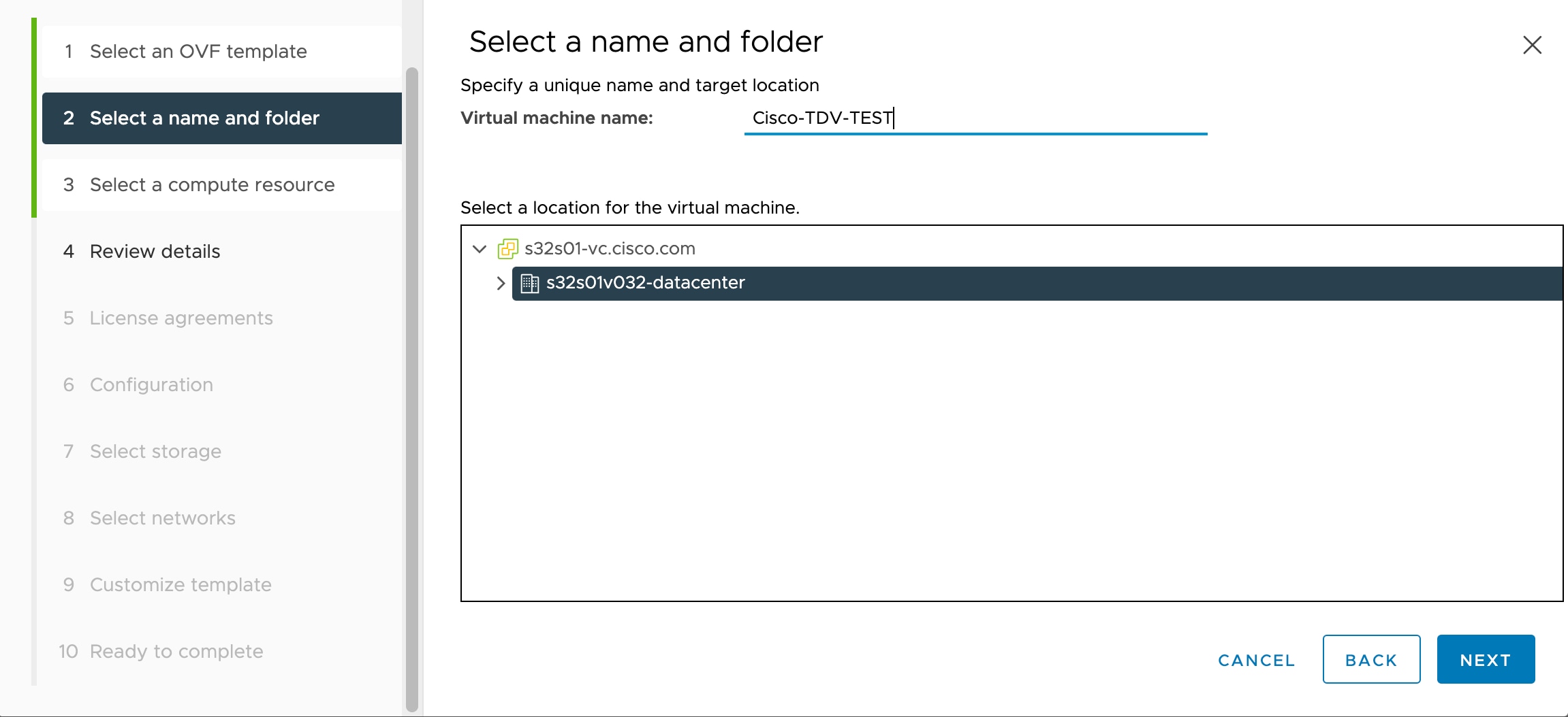
On the Select creation type page of the wizard, select Deploy a virtual machine from an OVF or OVA file and click Next.

Step 8

On the Select OVF and VMDK files page of the wizard:

  1. Enter a name for your Firewall Threat Defense Virtual machine.

    Virtual machine names can contain up to 80 characters and must be unique within each ESXi instance.

  2. Click the blue pane, browse to the directory where you unpacked the Firewall Threat Defense Virtual tar file, and choose the ESXi OVF template and the accompanying VMDK file:

    Cisco_Secure_Firewall_Threat_Defense_Virtual-ESXi-X.X.X-xxx.ovf

    Cisco_Secure_Firewall_Threat_Defense_Virtual-X.X.X-xxx.vmdk

    day0.iso

    where X.X.X-xx is the version and build number of the archive file you downloaded.

    Attention


    Make sure you select the ESXi OVF.

Step 9

Click Next.

Your local system storage opens.

Step 10

Choose a datastore from the list of accessible datastores on the Select storage page of the wizard.

The datastore stores the virtual machine configuration files and all of the virtual disks. Each datastore might have a different size, speed, availability, and other properties.

Step 11

Click Next.

Step 12

Configure the Deployment options that come packaged with the ESXi OVF for the Firewall Threat Defense Virtual:

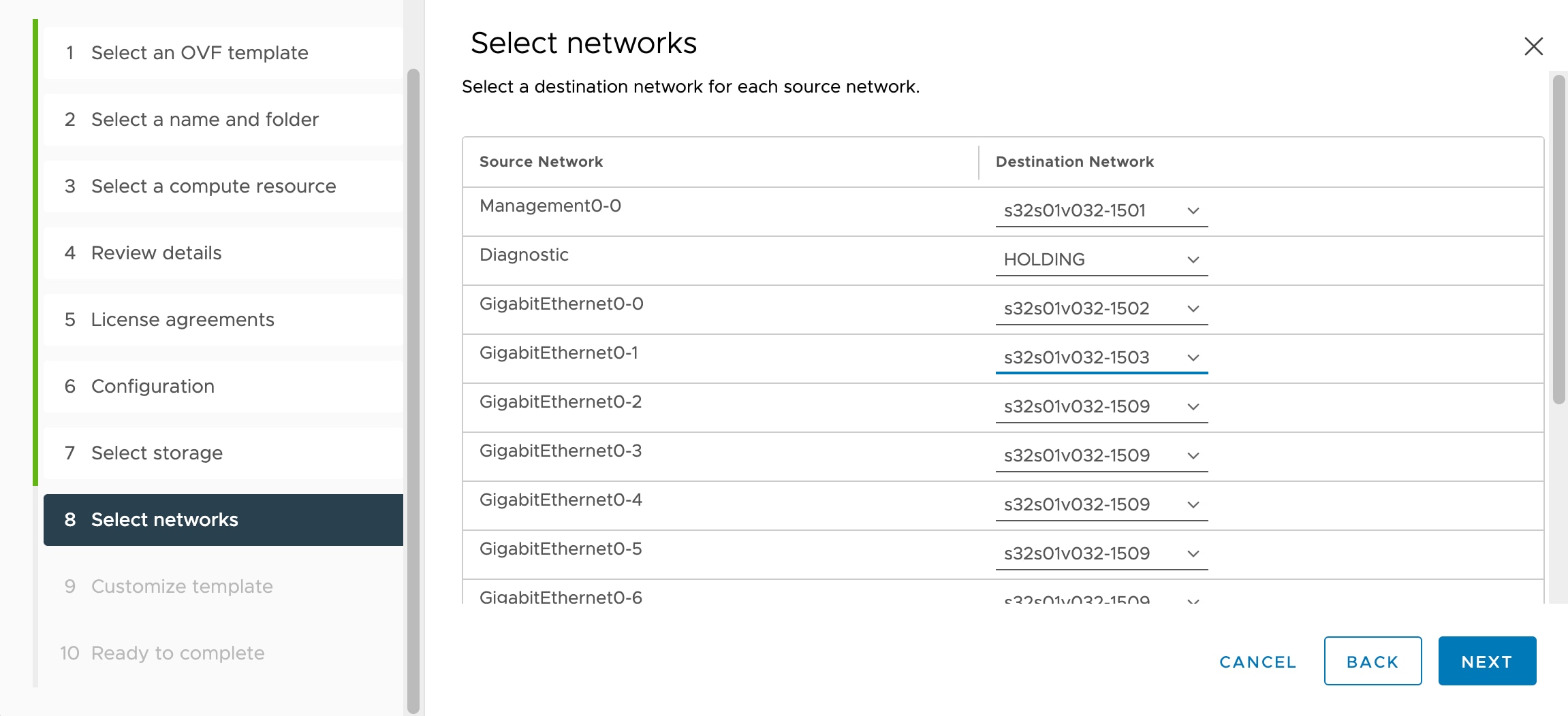
  1. Network Mapping—Map the networks specified in the OVF template to networks in your inventory, and then select Next.

    Ensure the Management0-0 interface is associated with a VM Network that is reachable from the Internet. Non-management interfaces are configurable from either the Firewall Management Center or from the Firewall Device Manager depending on your management mode.

    Important


    Firewall Threat Defense Virtual on VMware now defaults to vmxnet3 interfaces when you create a virtual device. Previously, the default was e1000. If you are using e1000 interfaces, we strongly recommend you switch. The vmxnet3 device drivers and network processing are integrated with the ESXi hypervisor, so they use fewer resources and offer better network performance.

    The networks may not be in alphabetical order. If it is too difficult to find your networks, you can change the networks later from the Edit Settings dialog box. After you deploy, right-click the Firewall Threat Defense Virtual instance, and choose Edit Settings. However, that screen does not show the Firewall Threat Defense Virtual IDs (only Network Adapter IDs).

    See the following concordance of Network Adapter, Source Networks and Destination Networks for Firewall Threat Defense Virtual interfaces (note these are the default vmxnet3 interfaces):

    Table 4. Source to Destination Network Mapping—VMXNET3

    Network Adapter

    Source Networks

    Destination Networks

    Function

    Network adapter 1

    Management0-0

    Management0/0

    Management

    Network adapter 2

    Reserved for internal use.

    Reserved for internal use.

    Reserved for internal use.

    Network adapter 3

    GigabitEthernet0-0

    GigabitEthernet0/0

    Outside data

    Network adapter 4

    GigabitEthernet0-1

    GigabitEthernet0/1

    Inside data

    Network adapter 5

    GigabitEthernet0-2

    GigabitEthernet0/2

    Data traffic (Optional)

    Network adapter 6

    GigabitEthernet0-3

    GigabitEthernet0/3

    Data traffic (Optional)

    Network adapter 7

    GigabitEthernet0-4

    GigabitEthernet0/4

    Data traffic (Optional)

    Network adapter 8

    GigabitEthernet0-5

    GigabitEthernet0/5

    Data traffic (Optional)

    Network adapter 9

    GigabitEthernet0-6

    GigabitEthernet0/6

    Data traffic (Optional)

    Network adapter 10

    GigabitEthernet0-7

    GigabitEthernet0/7

    Data traffic (Optional)

    You can have a total of 10 interfaces when you deploy the Firewall Threat Defense Virtual. For data interfaces, make sure that the Source Networks map to the correct Destination Networks, and that each data interface maps to a unique subnet or VLAN. You do not need to use all Firewall Threat Defense Virtual interfaces; for interfaces you do not intend to use, you can simply leave the interface disabled within the Firewall Threat Defense Virtual configuration.

  2. Disk provisioning—Select the disk format to store the virtual machine virtual disks.

    When you select Thick provisioned, all storage is immediately allocated. When you select Thin provisioned, storage is allocated on demand as data is written to the virtual disks. Thin provisioning can also reduce the amount of time it takes to deploy the virtual appliance.

Step 13

On the Ready to complete page of the New virtual machine wizard, review the configuration settings for the virtual machine.

  1. (Optional) Click Back to go back and review or modify the wizard settings.

  2. (Optional) Click Cancel to discard the creation task and close the wizard.

  3. Click Finish to complete the creation task and close the wizard.

    After you complete the wizard, the ESXi host processes the VM; you can see the deployment status in the Recent Tasks pane. A successful deployment shows Completed successfully under the Results column.

    The new Firewall Threat Defense Virtual virtual machine instance then appears under the Virtual Machines inventory of the ESXi host. Booting up the new virtual machine could take up to 30 minutes.

    Note


    To successfully register the Firewall Threat Defense Virtual with the Cisco Licensing Authority, the Firewall Threat Defense Virtual requires Internet access. You might need to perform additional configuration after deployment to achieve Internet access and successful license registration.


What to do next

  • Complete the set up of your virtual device using the CLI. This is the next step when you deploy the Firewall Threat Defense Virtual using the ESXi OVF template.

Complete the Firewall Threat Defense Virtual Unlimited Setup Using the CLI

If you deployed with an ESXi OVF template, you must set up the Firewall Threat Defense Virtual Unlimited using the CLI. Firewall Threat Defense Virtual Unlimited appliances do not have web interfaces. You can also use the CLI to configure System-required settings if you deployed with a VI OVF template and did not use the setup wizard during deployment.


Note


If you deployed with a VI OVF template and used the setup wizard, your virtual device is configured and no further device configuration is required. Your next steps depend on which management mode you choose.


When you first log in to a newly configured device, you must read and accept the EULA. Then, follow the setup prompts to change the administrator password, and configure the device’s network settings and firewall mode.

When following the setup prompts, for multiple-choice questions, your options are listed in parentheses, such as (y/n). Defaults are listed in square brackets, such as [y]. Press Enter to confirm a choice.
Procedure


Step 1

Open the VMware console.

Step 2

At the firepower login prompt, log in with the default credentials of username admin and the password Admin123.

Step 3

When the Firewall Threat Defense Virtual Unlimited system boots, a setup wizard prompts you for the following information required to configure the system:

  • Accept EULA

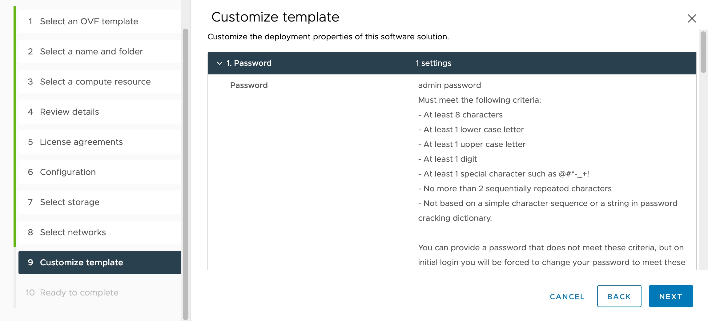
  • New admin password

  • IPv4 or IPv6 configuration

  • IPv4 or IPv6 DHCP settings

  • Management port IPv4 address and subnet mask, or IPv6 address and prefix

  • System name

  • Default gateway

  • DNS setup

  • HTTP proxy

  • Management mode (local management uses the Firewall Device Manager).

Step 4

Review the Setup wizard settings. Defaults or previously entered values appear in brackets. To accept previously entered values, press Enter.

The VMware console may display messages as your settings are implemented.

Step 5

Complete the system configuration as prompted.

Step 6

Verify the setup was successful when the console returns to the firepower # prompt.

Note

 
To successfully register the Firewall Threat Defense Virtual with the Cisco Licensing Authority, the Firewall Threat Defense Virtual requires Internet access. You might need to perform additional configuration after deployment to achieve Internet access and successful license registration.

Deploy the Firewall Threat Defense Virtual Unlimited on AWS

From Secure Firewall version 10.1, you can deploy Firewall Threat Defense Virtual Unlimited (FTDvU) on AWS.

Prerequisites

  • An AWS account. You can create one at http://aws.amazon.com/.

  • An SSH client (for example, PuTTY on Windows or Terminal on macOS) is required to access the Firewall Threat Defense Virtual console.

  • A Cisco Smart Account. You can create one at Cisco Software Central.

  • Firewall Threat Defense Virtual interface requirements:

    • Management interface (1) — Used to connect the Firewall Threat Defense Virtual to the Firewall Management Center.

      You can optionally configure a data interface for the Firewall Management Center management instead of the Management interface. The Management interface is a prerequisite for data interface management, so you still need to configure it in your initial setup. Note that Firewall Management Center access from a data interface is not supported in High Availability deployments. For more information about configuring a data interface for the Firewall Management Center access, see the configure network management-data-interface command in the FTD command reference.

    • Diagnostic interface (1) — Reserved for internal use.

      For Version 7.7 and below, diagnostic interface is mandatory. Minimum number of interfaces required is four. For Version 10.0 and above, diagnostic interface is optional. Minimum number of interfaces required is three.

      When deploying Firewall Threat Defense Virtual in AWS without diagnostic interface, it is mandatory to explicitly provide a Day 0 configuration that includes "Diagnostic": "OFF".

      Day0 configuration for Firewall Threat Defense Virtual without diagnostic interface

      Firewall Threat Defense Virtual Day0 start-up script example:
      
      {
      "AdminPassword": "<your_password",
      "Hostname": "ciscoftdv",
      "FirewallMode": "routed",
      "ManageLocally": "No",
      "Diagnostic": "OFF"
      }

      If this setting is not provided and the Firewall Threat Defense Virtual is launched with three interfaces, then the Firewall Threat Defense Virtual may fail to initialize, because the system expects the diagnostic interface by default.

    • Data interfaces (2) — Used to connect the Firewall Threat Defense Virtual to inside hosts and to the public network.

  • Communications paths:

    • Public/elastic IP addresses for access to the Firewall Threat Defense Virtual.

Hardware requirements

AWS ENA driver supported instance: Low-Latency Queue (LLQ) enabled. This means that LLQ mode is active on an Amazon Elastic Network Adapter (ENA). For more information on ENA and to verify if ENA is enabled, refer to Enable enhanced networking with ENA on your EC2 instances.


Note


We recommend using Nitro-v4 instance (c6in.16xlarge) for better performance.


CPU requirements

32/64 vCPUs

Memory (RAM)

Minimum of 64 GB RAM for FTDvU 32-core deployments

Minimum of 128 GB RAM for FTDvU 64-core deployments

Supported instances

Instance type

vCPUs/RAM

Applicable license

ENA queues

c6in.8xlarge

32 vCPUs / 64 GB

FTDvU

Default ENA queues per interface: 16

Maximum ENA queues per interface: 32

c6in.16xlarge

64 vCPUs / 128 GB

FTDvU

Default ENA queues per interface: 16

Maximum ENA queues per interface: 32

Prepare the AWS Environment for Firewall Threat Defense Virtual Unlimited

To deploy the Firewall Threat Defense Virtual on AWS you need to configure an Amazon VPC with your deployment-specific requirements and settings. In most situations a setup wizard can guide you through your setup. AWS provides online documentation where you can find useful information about the services ranging from introductions to advanced features. See https://aws.amazon.com/documentation/gettingstarted/ for more information.

For greater control over your AWS setup, the following sections o_er a guide to your VPC and EC2 configurations prior to launching the Firewall Threat Defense Virtual instances.

From ASA virtual version 9.24.10, you can use the ASAvU license for ASA Virtual deployment on AWS. ASAvU supports up to 64 vCPUs for deployments on AWS.

Create the VPC

A virtual private cloud (VPC) is a virtual network dedicated to your AWS account. It is logically isolated from other virtual networks in the AWS cloud. You can launch your AWS resources, such as the Firewall Management Center Virtual and the Firewall Threat Defense Virtual instances, into your VPC. You can configure your VPC; you can select its IP address range, create subnets, and configure route tables, network gateways, and security settings.

Procedure

Step 1

Log into https://console.aws.amazon.com/ and choose your region.

AWS is divided into multiple regions that are isolated from each other. The region is displayed in the upper right corner of your screen. Resources in one region do not appear in another region. Check periodically to make sure you are in the intended region.

Step 2

On the AWS Console Home, Click View all services > VPC.

Step 3

Click VPC Dashboard > Your VPCs.

Step 4

Click Create VPC.

Step 5

Enter the following in the Create VPC dialog box:

  1. A user-defined Name tag to identify the VPC.

  2. An IPv4 CIDR block of IP addresses. CIDR (Classless Inter-Domain Routing) notation is a compact representation of an IP address and its associated routing prefix. For example, 10.0.0.0/24.

  3. An IPv6 CIDR block of IP addresses. CIDR (Classless Inter-Domain Routing) notation is a compact representation of an IP address and its associated routing prefix. For example, [::/0].

  4. Select the IPv6 CIDR block as Amazon-provided IPv6 CIDR block to enable IPv6 in Virtual Private Cloud.

  5. A Tenancy setting of Default to ensure that instances launched in this VPC use the tenancy attribute specified at launch.

Step 6

Click Create VPC to create your VPC.


Add the Internet Gateway

You can add an Internet gateway to connect your VPC to the Internet. You can route traffic for IP addresses outside your VPC to the Internet gateway.

Before You Begin

  • Create a VPC for your Firewall Threat Defense Virtual instances.

Procedure

Step 1

On the AWS Console Home, click View all services > VPC.

Step 2

Click VPC Dashboard > Internet Gateways, and then click Create Internet Gateway.

Step 3

Enter a user-defined Name tag to identify the gateway and click Yes, Create to create the gateway.

Step 4

Select the gateway created in the previous step.

Step 5

Click Attach to VPC and select the VPC you created previously.

Step 6

Click Attach internet gateway to attach the gateway to your VPC.

By default, the instances launched on the VPC cannot communicate with the Internet until a gateway is created and attached to the VPC.


Add subnets

You can segment the IP address range of your VPC that the Firewall Threat Defense Virtual instances can be attached to. You can create subnets to group instances according to security and operational needs. For the Firewall Threat Defense Virtual, you need to create a subnet for management as well as subnets for traffic.

Before You Begin

  • Create a VPC for your Firewall Threat Defense Virtual instances.

Procedure

Step 1

On the AWS Console Home, click View all services > VPC.

Step 2

Click VPC Dashboard > Subnets, and then click Create Subnet. Select the VPC ID that you created previously.

Step 3

Enter the following in the Subnet settings dialog box:

  1. A user-defined Subnet name to identify the subnet.

  2. A VPC to use for this subnet.

  3. The Availability Zone where this subnet will reside. Select No Preference to let AWS select the zone.

  4. A CIDR block of IP addresses (IPv4 and IPv6). The range of IP addresses in the subnet must be a subset of the range of IP addresses in the VPC. Block sizes must be between a /16 network mask and a /28 network mask. The size of the subnet can equal the size of the VPC.

Step 4

Click Create subnet to create your subnet.

Step 5

Repeat steps 2 to 4 for as many subnets required. Create a separate subnet for management traffic and create as many subnets as needed for data traffic.


Add a route table

This route table is the management route table with routing to the internet gateway. It is specifically associated with the management subnet. Tra_ic subnets will have routes defined according to the customer's topology and do not need to route to the internet gateway. You can attach a route table to the gateway you configured for your VPC. Multiple subnets can be associated with a single route table, but each subnet can be associated with only one route table at a time

Procedure

Step 1

On the AWS Console Home, click View all services > VPC.

Step 2

Click VPC Dashboard > Route Tables, and then click Create route table. Enter a user-defined Name to identify the route table.

Step 3

Select the VPC that will use this route table.

Step 4

Click Create route table to create your route table. The route information is displayed in the Details pane.

Step 5

In the Routes tab, click Edit routes, and then click Add route.

  1. In the Destination column, enter 0.0.0.0/0 for IPv4 traffic or [::/0] for IPv6 traffic.

  2. In the Target column, select the internet gateway that you created earlier.

Step 6

Click Save changes.


Create security group

You can create a security group with rules specifying allowed protocols, ports and source IP ranges. Multiple security groups can be created with different rules which you can assign to each instance.

Procedure

Step 1

On the AWS Console Home, click View all services > EC2.

Step 2

Click EC2 > Network & Security > Security Groups.

Step 3

Click Create Security Group.

Step 4

Enter the following in the Create Security Group dialog box:

  1. A user-defined Security group name to identify the security group.

  2. A Description for this security group.

  3. The VPC associated with this security group.

Step 5

Configure Inbound and Outbound rules:

  1. In the Inbound rules tab, click Add Rule to add a rule for inbound traffic with the required parameters..

    Note


    HTTPS and SSH access is required to manage the Firewall Management Center Virtual from outside AWS. You should specify the source IP addresses accordingly. Also, if you are configuring both the Firewall Management Center Virtual and Firewall Threat Defense Virtual within the AWS VPC, you should allow the private IP management subnet access.

  2. In the Outbound rules tab, click Add Rule to add a rule for outbound traffic with the required parameters, or leave the defaults of All traffic (for Type) and Anywhere (for Destination).

Step 6

Click Create security group to create the security group.


Create network interfaces

You can create network interfaces for the Firewall Threat Defense Virtual using static IP addresses (IPv4 and IPv6) or DHCP. Create network interfaces (external and internal) as needed for your particular deployment.

Procedure

Step 1

On the AWS Console Home, click View all services > EC2.

Step 2

Click EC2 > Network & Security > Network interfaces.

Step 3

Click Create Network Interface.

Step 4

Enter the following in the Create network interface window:

  1. A optional user-defined Description for the network interface.

  2. Select a Subnet from the drop-down list. Make sure to select the subnet of the VPC where you want to create the Firewall Threat Defense Virtual instance.

  3. Enter a Private IP address. You can use a static IP address (IPv4 and IPv6) or Auto-generate (DHCP).

  4. Select one or more Security groups. Make sure the security group has all the required ports open.

Step 5

Click Create network interface to create your network interface.

Step 6

Select the network interface that you just created.

Step 7

Right-click and select Change Source/Dest. Check.

Step 8

Uncheck the Enable checkbox under Source/destination check and click Save.


Create elastic IP addresses

Elastic IP addresses are reserved public IP addresses that are used for remote access to the Firewall Threat Defense Virtual as well as other instances. When an instance is created, a public IP address is associated with the instance. That public IP address changes automatically when you STOP and START the instance. To avoid this, assign a persistent public IP address to the instance using Elastic IP addressing. At a minimum, you want to create elastic IP addresses for the Firewall Threat Defense Virtual management interface.

Procedure

Step 1

On the AWS Console Home, click View all services > EC2.

Step 2

Click EC2 > Network & Security > Elastic IPs.

Step 3

Click Allocate Elastic IP address.

Step 4

On the Allocate Elastic IP address settings dialog box, verify the settings and click Allocate to create the elastic IP address

Step 5

Repeat steps 3-4 for as many elastic IP addresses as required for your deployment.


Deploy the Firewall Threat Defense Virtual Unlimited on AWS

Before you begin

Cisco recommends the following:

  • Ensure that the AWS VPC and EC2 elements are configured.

  • Confirm that an AMI is available on the AWS Marketplace for the ASA Virtual instances.

Procedure


Step 1

Go to the AWS Marketplace and sign in.

Step 2

After you log in, search for either Cisco Secure Firewall ASA Virtual – BYOL or Cisco Secure Firewall ASA Virtual - PAYG based on your requirement. Click View Purchase Options after selecting the required ASA Virtual. Then, click Subscribe.

Step 3

Click Launch your software.

Step 4

Choose Amazon EC2. Then, choose Launch from EC2 Console.

Step 5

Select the required ASA Virtual Version and Region.

Step 6

Click Launch from EC2. The Launch an instance window comes up.

Step 7

Enter the Name and tags details.

Step 8

Verify the details in the Application and OS Images window.

Step 9

Select the Instance type from the drop-down list.

Step 10

In the Key pair section, click Create new key pair and enter the Key pair name.

Step 11

Click Create key pair. The .pem key pair file is downloaded.

Step 12

In the Network settings section, click Edit.

Step 13

Choose the required VPC and Subnet from the drop-down lists.

Note


If you have configured "Diagnostic": "ON" in the day-0 configuration script, a minimum of four subnets are required. If you have configured "Diagnostic": "OFF" in the day-0 configuration script, a minimum of three subnets are required.

Step 14

From the Auto-assign public IP drop-down list, choose Enable.

Step 15

Choose Select existing security group and choose the previously configured security group, or create a new security group. See AWS documentation for more information on creating security groups.

Step 16

Configure Storage. You can use the default values.

Step 17

Under Advanced Details, scroll down to Metadata accessible and choose Enabled to enable the IMDSv2 metadata.

Choose V2 only (token required) from the Metadata version drop-down list

Note


IMDSv2 is supported from version 7.4.3. For earlier versions, use V1 and V2.

Open the AWS CLI console and add the following arguments to enable IMDSv2 Required mode. For more information on the AWS CLI console, see AWS Command Line Interface.

Sample IMDSv2 configuration:


aws ec2 run-instances \
--image-id ami-0abcdef1234567890 \
--instance-type c6in.16xlarge \
...
--metadata-options "HttpEndpoint=enabled,HttpTokens=required"

Enter initial configuration data in the User data - optional box.

Caution


Use only plain text when entering data in the Advanced Details field. If you copy this information from a text editor, make sure you copy only as plain text. If you copy any Unicode data into the Advanced Details field, including white space, the instance may be corrupted and you will have to terminate the instance and re-create it.

Example:

Sample login configuration to manage the Firewall Threat Defense Virtual using the management center:


{
"AdminPassword": "<your_password>",
"Hostname": "<your_hostname>",
"IPv6Mode": "dhcp",
"IPv4Mode": "dhcp",
"ManageLocally": "No",
"FmcIp": "<IP address of FMC>",
"FmcRegKey":"<registration_passkey>",
"FmcNatId":"<NAT_ID_if_required>"
}

Sample login configuration to manage the Firewall Threat Defense Virtual using the device manager:


{
"AdminPassword": "<your_password>",
"Hostname": "<your_hostname>",
"ManageLocally": "Yes"
}

Step 18

Click Launch instance. A success banner is displayed after the instance is launched successfully.

Step 19

Go to the AWS Console Home and click View All Services > EC2 > Network & Security > Network Interfaces.

Step 20

Find the traffic interfaces previously created, then click Attach.

Step 21

Go to the AWS Console Home and click View All Services > EC2 > Instances > Instances.

Step 22

Right-click the Instance ID, and select Monitor and troubleshoot > Get system log to view the status.

Note


There will possibly be a warning of a connectivity issue. This is expected, since the eth0 interface will not be active until the EULA is completed.

Step 23

Register the Firewall Threat Defense Virtual on the Management Center. Ensure that you select the Unlimited perfomance tier when you are choosing the licenses to be applied.

See How to Manage Secure Firewall Threat Defense Virtual Device for an overview of how to choose your management option.