Features
The Cisco Firepower 1100 series security appliances are a standalone modular security services platform. They are capable of running multiple security services simultaneously and so are targeted at the data center as a multiservice platform.
The Firepower 1100 series supports Cisco Secure Firewall Threat Defense and Cisco Secure Firewall ASA software.
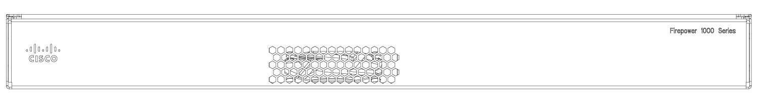
The following figure shows the Cisco Firepower 1100 series chassis.
The following table lists the features for the Firepower 1100.
|
Feature |
1120 |
1140 |
1150 |
||
|---|---|---|---|---|---|
|
Form factor |
1 RU |
||||
|
Mounting |
Rack mount 4-post Electronic Industries Association (EIA)-310-D rack |
||||
|
Airflow |
I/O side to non-I/O side Rear panel to front panel (cold aisle to hot aisle) |
||||
|
Memory |
16-GB DDR4 DRAM |
32-GB DDR4 DRAM |
|||
|
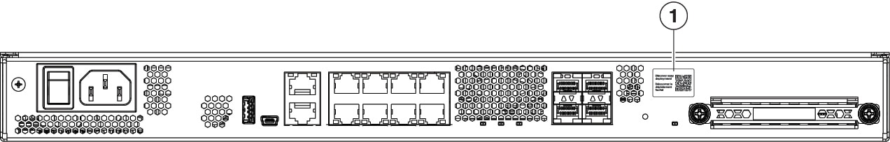
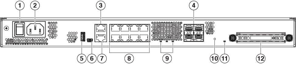
Management port |
One Gigabit Ethernet RJ-45 10/100/1000 BaseT Restricted to network management access only |
||||
|
Console ports |
One RJ-45 or one USB Mini B Provides management access through an external system |
||||
|
USB port |
One USB 3.0 Type A Allows attachment of an external device such as mass storage |
||||
|
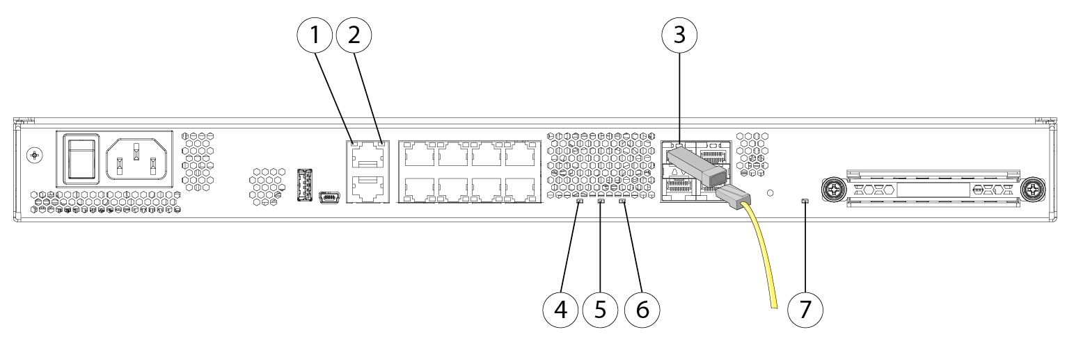
Network ports |
Eight Gigabit Ethernet RJ-45 10/100/1000 BaseT Each RJ-45 (8P8C) copper port supports auto Medium Dependent Interface Crossover (MDI/X) as well as auto-negotiation for interface speed, duplex, and other negotiated parameters, and are MDI/X-compliant. Port numbering is left to right, top to bottom; ports are named Gigabit Ethernet 1/1 through 1/8. Each port includes a pair of LEDs, one each for connection status and link status. |
||||
|
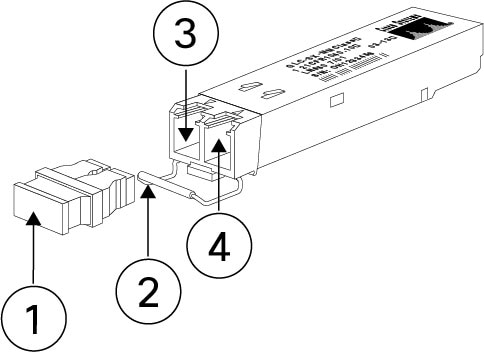
Small form-factor pluggable (SFP) ports |
Four fixed 1-Gbps SFP ports |
Four fixed 1-Gb SFP ports
|
|||
|
Supported SFPs |
See Supported transceivers for a list of supported transceivers. |
||||
|
Power switch |
Yes On rear panel; standard rocker-type power on/off switch
|
||||
|
Reset button |
Yes A small recessed button that if pressed for longer than three seconds resets the chassis to its default state following the next reboot. Configuration variables are reset to factory default. However, the flash is not erased, and no files are removed. |
||||
|
AC power supply |
One fixed AC power supply The power supply is internal; there is no user access. The power supply is not field-replaceable; you must return the chassis to Cisco for power supply replacement. |
||||
|
Redundant power |
No |
||||
|
Fan |
One fixed fan The fan is internal; there is no user access. The fan is not field-replaceable; you must return the chassis to Cisco for fan replacement. |
||||
|
Storage |
One SSD slot 200-GB 2.5-in. SATA SSD drive The drive is field-replaceable. |
||||


 Feedback