Rack mount the Chassis

Unpack and inspect the chassis


Note


The chassis is thoroughly inspected before shipment. If any damage occurred during transportation or any items are missing, contact your customer service representative immediately. Keep the shipping container in case you need to send the chassis back due to damage.


Procedure


Step 1

Remove the chassis from its cardboard container and save all packaging material.

Step 2

Compare the shipment to the equipment list provided by your customer service representative. Verify that you have all items.

Step 3

Check for damage and report any discrepancies or damage to your customer service representative. Have the following information ready:

  • Invoice number of shipper (see the packing slip)

  • Model and serial number of the damaged unit

  • Description of damage

  • Effect of damage on the installation


Rack mount the chassis

The chassis ships with rack-mount brackets and four screws that you can install on the front or the rear of the chassis. We recommend you install the rack-mount brackets on the I/O side (rear panel) so that the front of the chassis faces the hot aisle.

The rack is a standard Electronic Industries Association (EIA) rack. It is a 4-post-EIA-310-D, which is the current revision as specified by EIA. The vertical hole spacing alternates at .50 inches (12.70 mm) to .625 inches (15.90 mm) to .625 inches (15.90 mm) and repeats. The start and stop space is in the middle of the .50-inch holes. The horizontal spacing is 18.312 inches (465.1 mm), and the rack opening is specified as a minimum of 17.75 inches (450 mm).

Procedure


Step 1

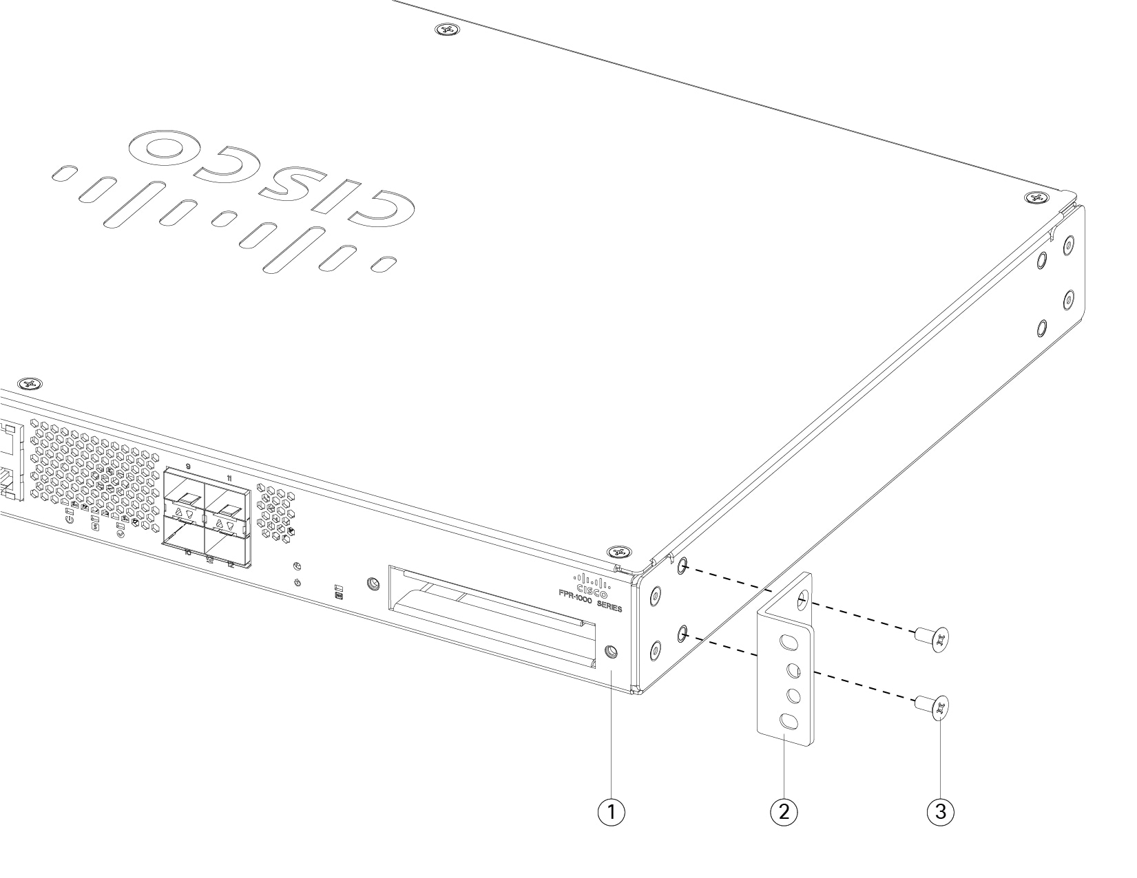
Attach both brackets to the sides of the chassis using the four M4 x 8-mm Phillips screws that shipped with your chassis. After the brackets are secured to the chassis, you can mount it in the rack.

Figure 1. Attach brackets to chassis
Attach brackets to chassis

1

Chassis back panel

2

Rackmount bracket

3

M4 x 8-mm Phillips screws (two per side)

Step 2

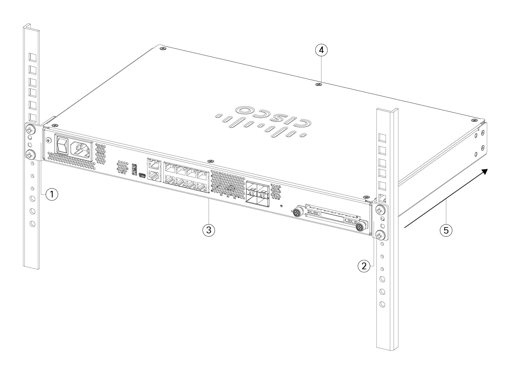
Attach the chassis to the rack using the screws that you supply for your rack.

We recommend that you install the chassis with the I/O side (rear panel) facing the cold aisle. See the following illustration for an example of air flow from rear panel (cold aisle) to the front panel (hot aisle).

Figure 2. Install the chassis in the rack
Install the chassis in the rack

1

Rackmount bracket

2

Rackmount bracket

3

Cold aisle

Chassis I/O side (rear panel)

4

Hot aisle

Chassis non-I/O side (front panel)

5

Air flow direction (I/O side to non-I/O side)


What to do next

You can now install the cables and power cord, as described in the Cisco Firepower 1100 Getting Started Guide.

Install the FIPS opacity shield in a two-post rack


Note


Because the FIPS opacity shield covers the serial number on the chassis, the CO should copy the serial number and store it in a secure place. The serial number is needed when you call Cisco TAC.


Before you begin


Caution


This procedure should be performed only by the Crypto Officer (CO).


You need the following items to install the FIPS opacity shield:

  • #1 Phillips screwdriver

  • The following items from the FIPS kit:

    • One FIPS opacity shield

    • Two cable management brackets

    • Eight Phillips 8-32 x 0.375-inch screws used to attach the FIPS opacity shield to the cable management brackets

    • Ten Tamper Evidence Labels (TEL)


      Note


      The TELs are made of a special thin gauge vinyl with self-adhesive backing. Once the CO attaches them on the chassis, any attempt to open the chassis damages the TELs or the chassis cover. Because the TELs have nonrepeated serial numbers, the CO can inspect them for damage and compare them against the applied serial numbers to verify whether the chassis has been tampered with. TELs with curled corners, rips, and slices indicate tampering. The word “FIPS” or “OPEN” may appear if the label has been peeled back.


Procedure


Step 1

Copy the serial number and store in a secure place.

Step 2

If you haven't already done so, attach both rackmount brackets to the sides of the chassis using the four M4 x 8-mm Phillips screws that shipped with your chassis.

Figure 3. Attach brackets to chassis
Attach brackets to chassis

1

Chassis back panel

2

Rackmount bracket

3

M4 x 8-mm Phillips screws (two per side)

Step 3

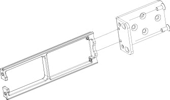
Install the cable management brackets.

Figure 4. Install the cable management screws into the Rackmount bracket
Install the cable management screws into the Rackmount bracket

Step 4

Connect the cables to the ports. Make sure that the cables have enough slack to route them through the cable mounting brackets.

Note


If you are installing the FIPS opacity shield after the initial product installation, the cables are connected. If the attached cables do not have enough slack to route them through the cable mounting brackets (as shown in the figure below), you will have to turn the power off on the appliance, remove the cables, route the cables through the cable mounting brackets, reattach the cables, and continue with Step 5 below.

Note


When you toggle the power switch from ON to OFF, it takes several seconds for the system to power down. Do not remove the power cable until the power LED is off. After removing power from the chassis either by moving the power switch to OFF or unplugging the power cord, wait at least 10 seconds before turning power back ON.

Step 5

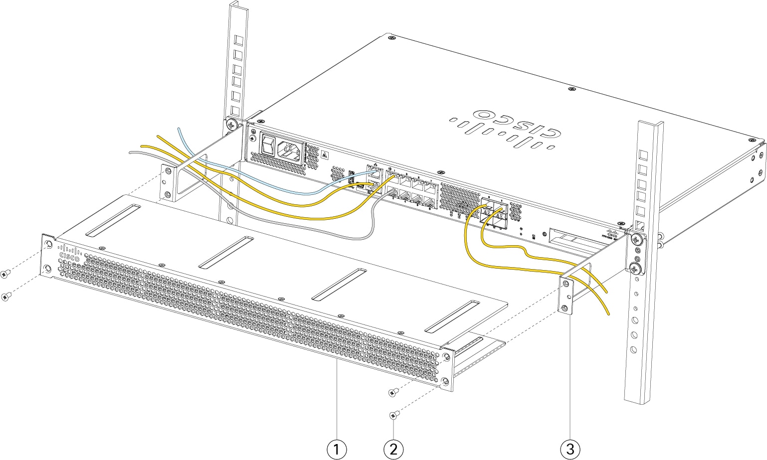
Route the cables through the openings in the cable management brackets as shown in the figure below.

Step 6

Attach the FIPS opacity shield to the cable management brackets using four of the 8-32 x 0.375-inch Phillips screws provided in the FIPS kit as shown in the figure below.

Figure 5. Install the FIPS cover
Install the FIPS cover

1

FIPS opacity shield

2

8-32 x 0.375-inch Phillips screws (two per side)

3

Cable management bracket

Step 7

Before you attach the TELs, clean the chassis and FIPS cover of any grease, dirt, or oil with alcohol-based cleaning pads .

Step 8

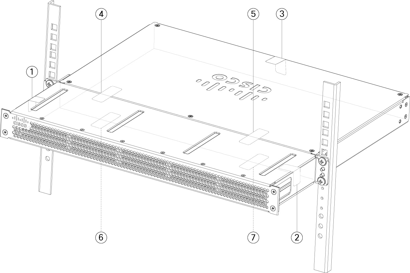
Attach seven of the TELs. See the figure below for the correct placement. Allow the TELs to cure for a minimum of 12 hours.

Caution


Any deviation in the placement of the TELs means the chassis is not in FIPS mode.

Figure 6. TELs placement on the chassis
TELs placement on the chassis

1

TEL 1 on the left side and top of chassis

2

TEL 2 on the right side and top of chassis

3

TEL 3 on the top and back of chassis

4

TEL 4 across the FIPS shield and the chassis (towards the left of the chassis)

5

TEL 5 across the FIPS shield and the chassis (towards the right of the chassis)

6

TEL 6 on the bottom of the chassis towards the left side of the chassis

7

TEL 7 on the bottom of the chassis towards the right side of the chassis

Step 9

Attach the power cable to the chassis and connect it to an electrical outlet.

Step 10

Press the power switch on the rear panel.

Step 11

Check the power LED on the front panel. Solid green indicates that the chassis is powered on.

Step 12

Place the chassis in FIPS mode.

See the following procedures for how to place the chassis in FIPS mode:


What to do next

See the Cisco Firepower 1100 Getting Started Guide for further configuration information.