Outlines essential network configuration examples for deploying Cisco Cyber Vision sensors, detailing VLAN settings, IP addressing, ERSPAN/RSPAN configurations, and deployment scenarios across various Cisco Catalyst switch series to ensure proper sensor communication and traffic monitoring.
This chapter provides examples of essential network configurations required to deploy Cisco Cyber Vision sensors on supported devices. Understanding these configurations is crucial for ensuring proper communication between the Center and the deployed sensors, as well as for effective traffic monitoring.
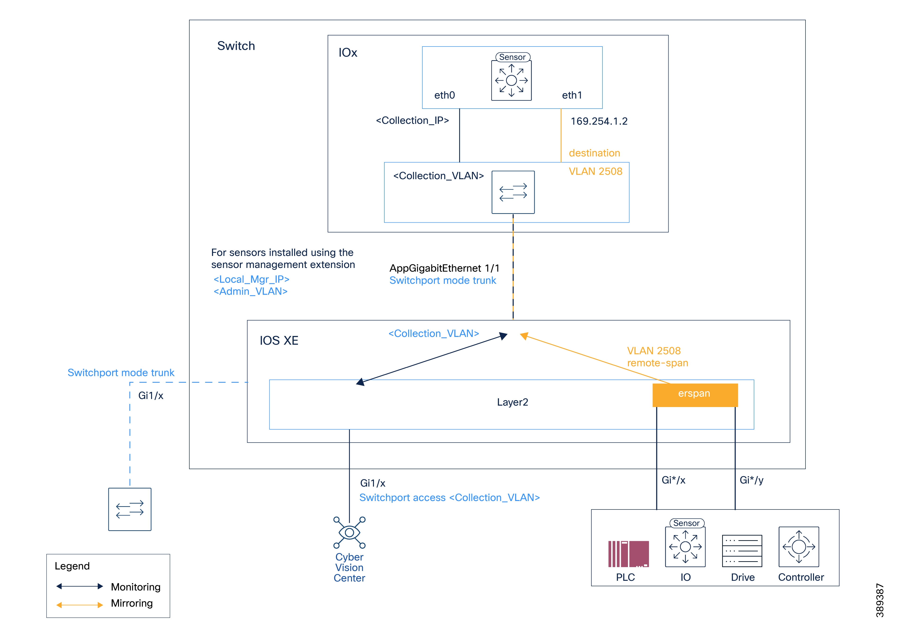
In these examples:
-
VLAN 49 is the collection VLAN.
-
VLAN 2508 is the mirroring VLAN.
-
192.168.49.40 with the subnet mask 255.255.255.0 is the SVI management address, typically configured on the collection VLAN or on the network gateway.
-
169.254.x.x IP range with the subnet mask 255.255.255.252 is used to configure ERSPAN origins and destinations.
The configuration examples provided in this guide demonstrate deploying sensors in Cisco Catalyst IE3x00, Cisco Catalyst IE9x00, and Cisco Catalyst 9x00 switches, in the following deployment scenarios:
-
Center and sensors are in the same network.
-
Center and sensors are in different networks.
-
(IE3x00 switches only) Platform and sensors are in different networks, requiring L3NAT-IOx.
For Cisco Catalyst 9300, specific examples are provided for ERSPAN and RSPAN configurations.
There are some important differences in sensor configurations, based on the network deployment setup and the devices on which the sensor is deployed.
| Switch series |
Center and sensors in the same network |
Center and sensors in different networks |
|---|---|---|
| Cisco Catalyst IE3x00 |
Use the |
|
| Cisco Catalyst IE9x00 |
None |
Use |
| Cisco Catalyst 9x00 |
Use the |
Use the |