Deploy the ASA Virtual Unlimited

Overview

From ASA virtual version 9.22, ASA Virtual supports a new performance tier license - ASA Virtual Unlimited (ASAvU).

From ASA virtual version 9.22, you can use the ASAvU license for ASA Virtual deployments on KVM and VMware. ASAvU supports up to 32 vCPUs for deployments on KVM and VMware.

From ASA virtual version 9.24.10, you can use the ASAvU license for ASA Virtual deployment on AWS. ASAvU supports up to 64 vCPUs for deployments on AWS.

Licensing

ASA Virtual supports performance-tier licensing. From Version 9.22, a new performance tier license ASA Virtual Unlimited (ASAvU) is introduced. ASAvU supports deployments with up to 32 vCPUs and 64 GB memory on KVM and VMware. ASAvU supports deployments with up to 64 vCPUs and 128 GB memory on AWS. For more information about licensing and performance tiers, see the Smart Software Licensing chapter in the Cisco Secure Firewall ASA Series General Operations CLI Configuration Guide.

Table 1. ASA Virtual Unlimited License Entitlements

Performance Tier

Device Specifications (vCPU/RAM)

Supported platforms

ASAv - Unlimited (ASAvU)

32 vCPU/64 GB

KVM, VMware, AWS

ASAv - Unlimited (ASAvU)

64 vCPU/128 GB

AWS

Deploy the ASA Virtual Unlimited on KVM

From ASA virtual version 9.22, you can deploy ASA Virtual Unlimited (ASAvU) on KVM.

Prerequisites

Hardware Requirements

  • Cisco UCS M7, M8 servers, or later.

  • x86-based processors (64 cores per socket or higher recommended).

  • 100 Gigabit Ethernet NICs - Intel E810 series or NVIDIA/Mellanox ConnectX-6 card.

CPU/Memory Requirements

32 vCPU/64 GB RAM

Guidelines and Limitations

Ensure that you read the generic guidelines and limitations for deploying ASA Virtual on KVM.

NUMA Optimization Guidelines for ASAvU

  • Always enforce Single-NUMA placement. Cross-socket memory access introduces significant latency and throughput penalties.

  • Ensure all vCPUs are pinned to a single physical NUMA node. Avoid vCPU/memory pinning across NUMA boundaries to maintain strict memory locality.

Prepare the Day-0 Configuration File

To prepare the Day-0 configuration file used during deployment, see the Prepare the Day-0 Configuration File section in the Deploy the ASA Virtual on KVM chapter.

Prepare the Virtual Bridge XML Files

You need to set up virtual networks that connect the ASA Virtual guests to the KVM host and that connect the guests to each other.


Note


This procedure does not establish connectivity to the external world outside the KVM host.


Prepare the virtual bridge XML files on the KVM host. For the sample virtual network topology described in Prepare the Day 0 Configuration File, you need the following three virtual bridge files: virbr1.xml, virbr2.xml, and virbr3.xml (you must use these three filenames; for example, virbr0 is not allowed because it already exists). Each file has the information needed to set up the virtual bridges. You must give the virtual bridge a name and a unique MAC address. Providing an IP address is optional.

Procedure


Step 1

Create three virtual network bridge XML files. For example, virbr1.xml, virbr2.xml, and virbr3.xml:

Example:


<network>
<name>virbr1</name>
<bridge name='virbr1' stp='on' delay='0' />
<mac address='52:54:00:05:6e:00' />
<ip address='192.168.1.10' netmask='255.255.255.0' />
</network>

Example:


<network>
<name>virbr2</name>
<bridge name='virbr2' stp='on' delay='0' />
<mac address='52:54:00:05:6e:01' />
<ip address='10.1.1.10' netmask='255.255.255.0' />
</network>

Example:


<network>
<name>virbr3</name>
<bridge name='virbr3' stp='on' delay='0' />
<mac address='52:54:00:05:6e:02' />
<ip address='198.51.100.10' netmask='255.255.255.0' />
</network>

Step 2

Create a script that contains the following (in our example, we name the script virt_network_setup.sh):

virsh net-create virbr1.xml
virsh net-create virbr2.xml
virsh net-create virbr3.xml

Step 3

Run this script to set up the virtual network. The script brings up the virtual networks. The networks stay up as long as the KVM host is running.

stack@user-ubuntu:-/KvmAsa$ virt_network_setup.sh

Note


If you reload the Linux host, you must rerun the virt_network_setup.sh script. It does not persist over reboots.

Step 4

Verify that the virtual networks were created:


stack@user-ubuntu:-/KvmAsa$ brctl show
bridge name bridge id STP enabled Interfaces
virbr0 8000.0000000000000 yes
virbr1 8000.5254000056eed yes virb1-nic
virbr2 8000.5254000056eee yes virb2-nic
virbr3 8000.5254000056eec yes virb3-nic
stack@user-ubuntu:-/KvmAsa$

Step 5

Display the IP address assigned to the virbr1 bridge. This is the IP address that you assigned in the XML file.


stack@user-ubuntu:-/KvmAsa$ ip address show virbr1
S: virbr1: <NO-CARRIER,BROADCAST,MULTICAST,UP> mtu 1500 qdisc noqueue state DOWN
link/ether 52:54:00:05:6e:00 brd ff:ff:ff:ff:ff:ff
inet 192.168.1.10/24 brd 192.168.1.255 scope global virbr1
valid_lft forever preferred_lft forever

Launch Using a Deployment Script

Use a virt-install based deployment script to launch the ASA Virtual.

Procedure


Step 1

Create a virt-install script called “virt_install_asav.sh.”

The name of the ASA Virtual machine must be unique across all other VMs on this KVM host.

The ASA Virtual supports up to 10 networks. This example uses three networks. The order of the network bridge clauses is important. The first one listed is always the management interface of the ASA Virtual (Management 0/0), the second one listed is GigabitEthernet 0/0 of the ASA Virtual, and the third one listed is GigabitEthernet 0/1 of the ASA Virtual, and so on up through GigabitEthernet 0/8. The virtual NIC must be Virtio.

Example:

For Secure Boot Configuration: Use virt-install command with specific parameters.

virt-install \ 
  --connect=qemu:///system \ 
  --network bridge:br1556,model=virtio\ 
  --network bridge:br-in,model=virtio\ 
  --network bridge:br-out,model=virtio\ 
  --name=<prefix>-vm-asav \ 
  --cpu host \ 
  --arch=x86_64 \ 
  --vcpus=32 \ 
  --ram=65536 \ 
  --os-type=linux \ 
  --os-variant=generic \ 
  --virt-type=kvm \ 
  --import \ 
  --watchdog i6300esb,action=reset \
  --disk path=<path to qcow2 file>,format=qcow2,device=disk,bus=virtio,cache=none \ 
  --disk path=<path to day0.iso file>,format=iso,device=cdrom,bus=sata \ 
  --console pty,target_type=serial \ 
  --serial tcp,host=127.0.0.1:<port>,mode=bind,protocol=telnet \
  --boot firmware=efi,loader_secure=yes \ 
  --machine q35 \   
  --features smm.state=on \ 
  --force 

Note


Machine type must be q35 and SMM (System Management Mode) must be ON for Secure Boot.

VM Management:

Note


To delete a VM, use the following command:

virsh undefine <vm-name> --nvram

Note


From Secure Firewall ASA version 9.22, with the ASAvU license, you can enter 32 core (vcpus parameter in the example above) with 65536 MB (64 GB) RAM (ram parameter in the example above) to remove the rate limiter.

Step 2

Run the virt_install script:

Example:

stack@user-ubuntu:-/KvmAsa$ ./virt_install_asav.sh 

Starting install...
Creating domain...
A window appears displaying the console of the VM. You can see that the VM is booting. It takes a few minutes for the VM to boot. Once the VM stops booting you can issue CLI commands from the console screen.

Launch Using a Graphical User Interface

There are several open-source options available to manage KVM virtual machines using a GUI. The following procedure uses virt-manager, also known as Virtual Machine Manager, to launch the ASA Virtual. virt-manager is a graphical tool for creating and managing guest virtual machines.


Note


KVM can emulate a number different of CPU types. For your VM, you typically should select a processor type which closely matches the CPU of the host system, as it means that the host CPU features (also called CPU flags) will be available in your VMs. You should set the CPU type to host in which case the VM will have exactly the same CPU flags as your host system.


Procedure


Step 1

Start virt-manager (Applications > System Tools > Virtual Machine Manager).

You may be asked to select the hypervisor and/or enter your root password.

Step 2

Click the button in the top left corner to open the New VM wizard.

Step 3

Enter the virtual machine details:

  1. For the operating system, select Import existing disk image.

    This method allows you to import a disk image (containing a pre-installed, bootable operating system) to it.

  2. Click Forward to continue.

Step 4

Load the disk image:

  1. Click Browse... to select the image file.

  2. Choose Generic for the OS type.

  3. Click Forward to continue.

Step 5

Configure the memory and CPU options:

  1. Set the Memory (RAM) parameter for your ASA Virtual platform size.

  2. Set the corresponding CPUs parameter for the ASA Virtual platform size.

  3. Click Forward to continue.

Step 6

Check the Customize configuration before install box, specify a Name, then click Finish.

Doing so opens another wizard that allows you to add, remove, and configure the virtual machine's hardware settings.

Step 7

Modify the CPU configuration:

From the left panel, select Processor, then select Configuration > Copy host CPU configuration.

This applies the physical host's CPU model and configuration to your VM.

Step 8

Configure the Virtual Disk:

  1. From the left panel, select Disk 1.

  2. Select Advanced options.

  3. Set the Disk bus to Virtio.

  4. Set the Storage format to qcow2.

Step 9

Configure a serial console:

  1. From the left panel, select Console.

  2. Select Remove to remove the default console.

  3. Click Add Hardware to add a serial device.

  4. For Device Type, select TCP net console (tcp).

  5. For Mode, select Server mode (bind).

  6. For Host, enter 0.0.0.0 for the IP address, then enter a unique Port number.

  7. Check the Use Telnet box.

  8. Configure device parameters.

Step 10

Configure a watchdog device to automatically trigger some action when the KVM guest hangs or crashes:

  1. Click Add Hardware to add a watchdog device.

  2. For Model, select default.

  3. For Action, select Forcefully reset the guest.

Step 11

Configure network interfaces.

Click Add Hardware to add an interface, then choose macvtap or specify a shared device name (use a bridge name).

Interface mapping is as given below:

vnic0—Management interface

vnic1— Outside interface

vnic2—Inside interface

Step 12

If deploying using a Day 0 configuration file, create a virtual CD-ROM for the ISO:

  1. Click Add Hardware.

  2. Select Storage.

  3. Click Select managed or other existing storage and browse to the location of the ISO file.

  4. For Device type, select IDE CDROM.

Step 13

After configuring the virtual machine's hardware, click Apply.

Step 14

Click Begin installation for virt-manager to create the virtual machine with your specified hardware settings.

Note

 
When launching the ASA Virtual in virt-manager, a graphical (SPICE) console opens by default. On some systems, this console may appear frozen or show only partial output during boot. However, the device continues to boot normally in the background.

To view the full console output, go to:

View → Consoles → Console or Serial

If a TCP serial console is configured, use telnet to access the console instead — output will not appear in virt-manager.


Deploy the ASA Virtual Unlimited on VMware

From ASA virtual version 9.22, you can deploy ASA Virtual Unlimited (ASAvU) on VMware.

Prerequisites

Hardware Requirements

  • Cisco UCS M7, M8 servers, or later.

  • x86-based processors (64 cores per socket or higher recommended).

  • 100 Gigabit Ethernet NICs - Intel E810 series or NVIDIA/Mellanox ConnectX-6 card.

CPU/Memory Requirements

32 vCPU/64 GB RAM

Guidelines and Limitations

Ensure that you read the generic guidelines and limitations for deploying ASA Virtual on VMware.

NUMA Optimization Guidelines for ASAvU

  • Always enforce Single-NUMA placement. Cross-socket memory access introduces significant latency and throughput penalties.

  • Set "numa.autosize.vcpu.maxPerVirtualNode" to ≤ physical cores per socket. Exceeding this value forces the hypervisor to span sockets, degrading performance.

Unpack the ASA Virtual Software and Create a Day 0 Configuration File

You can prepare a Day 0 configuration file before you launch the ASA Virtual. This file is a text file that contains the ASA Virtual configuration to be applied when the ASA Virtual is launched. This initial configuration is placed into a text file named “day0-config” in a working directory you chose, and is manipulated into a day0.iso file that is mounted and read on first boot. At the minimum, the Day 0 configuration file must contain commands to activate the management interface and set up the SSH server for public key authentication, but it can also contain a complete ASA configuration. A default day0.iso containing an empty day0-config is provided with the release. The day0.iso file (either your custom day0.iso or the default day0.iso) must be available during first boot.

Before you begin

We are using Linux in this example, but there are similar utilities for Windows.

  • To automatically license the ASA Virtual during initial deployment, place the Smart Licensing Identity (ID) Token that you downloaded from the Cisco Smart Software Manager in a text file named ‘idtoken’ in the same directory as the Day 0 configuration file.

  • If you want to access and configure the ASA Virtual from the serial port on the hypervisor instead of the virtual VGA console, you should include the console serial setting in the Day 0 configuration file to use the serial port on first boot.

  • If you want to deploy the ASA Virtual in transparent mode, you must use a known running ASA config file in transparent mode as the Day 0 configuration file. This does not apply to a Day 0 configuration file for a routed firewall.

  • See the OVF file guidelines in Guidelines and Limitations for additional information about how the ISO images are mounted on the ESXi hypervisor.

Procedure


Step 1

Download the ZIP file from Cisco.com, and save it to your local disk:

https://www.cisco.com/go/asa-software

Note


A Cisco.com login and Cisco service contract are required.

Step 2

Unzip the file into a working directory. Do not remove any files from the directory. The following files are included:

  • asav-vi.ovf—For vCenter deployments.

  • asav-esxi.ovf—For non-vCenter deployments.

  • boot.vmdk—Boot disk image.

  • disk0.vmdk—ASA Virtual disk image.

  • day0.iso—An ISO containing a day0-config file and optionally an idtoken file.

  • asav-vi.mf—Manifest file for vCenter deployments.

  • asav-esxi.mf—Manifest file for non-vCenter deployments.

Step 3

Enter the CLI configuration for the ASA Virtual in a text file called “day0-config.” Add interface configurations for the three interfaces and any other configuration you want.

The fist line should begin with the ASA version. The day0-config should be a valid ASA configuration. The best way to generate the day0-config is to copy the desired parts of a running config from an existing ASA or ASA Virtual. The order of the lines in the day0-config is important and should match the order seen in an existing show running-config command output.

We provide two examples of the day0-config file. The first example shows a day0-config when deploying an ASA Virtual with Gigabit Ethernet interfaces. The second example shows a day0-config when deploying an ASA Virtual with 10 Gigabit Ethernet interfaces. You would use this day0-config to deploy an ASA Virtual with SR-IOV interfaces; see Guidelines and Limitations.

Example:

ASA Version 9.24.10
!
console serial
interface Management0/0
nameif management
security-level 100
ip address 192.168.1.1 255.255.255.0
no shutdown
interface Gigabitethernet0/0
nameif inside
security-level 100
ip address 10.1.1.2 255.255.255.0
no shutdown
interface Gigabitethernet0/1
nameif outside
security-level 0
ip address 198.51.100.2 255.255.255.0
no shutdown
http server enable
http 192.168.1.0 255.255.255.0 management
crypto key generate rsa modulus 1024
username AdminUser password paSSw0rd
ssh 192.168.1.0 255.255.255.0 management
aaa authentication ssh console LOCAL
call-home
http-proxy 10.1.1.1 port 443
license smart
feature tier standard
throughput level 2G

Example:

ASA Version 9.8.1
!
console serial
interface Management 0/0
management-only
nameif management
security-level 0
ip address 192.168.0.230 255.255.255.0
!
interface Gigabitethernet0/0
nameif inside
security-level 100
ip address 10.10.10.10 255.255.255.0
ipv6 address 2001:10::1/64
!
interface Gigabitethernet0/1
nameif outside
security-level 0
ip address 10.10.20.10 255.255.255.0
ipv6 address 2001:20::1/64
!
route management 0.0.0.0 0.0.0.0 192.168.0.254
!
username cisco password cisco123 privilege 15
!
aaa authentication ssh console LOCAL
ssh 0.0.0.0 0.0.0.0 management
ssh timeout 60
ssh version 2
!
http 0.0.0.0 0.0.0.0 management
!
logging enable
logging timestamp
logging buffer-size 99999
logging buffered debugging
logging trap debugging
!
dns domain-lookup management
DNS server-group DefaultDNS
name-server 64.102.6.247
!
license smart
feature tier standard
throughput level 10G
!
crypto key generate rsa modulus 2048

Step 4

(Optional) Download the Smart License identity token file issued by the Cisco Smart Software Manager to your PC.

Step 5

(Optional) Copy the ID token from the download file and put it in a text file named ‘idtoken’ that only contains the ID token.

The Identity Token automatically registers the ASA Virtual with the Smart Licensing server.

Step 6

Generate the virtual CD-ROM by converting the text file to an ISO file:

Example:

stack@user-ubuntu:-/KvmAsa$ sudo genisoimage -r -o day0.iso day0-config idtoken
I: input-charset not specified, using utf-8 (detected in locale settings)
Total translation table size: 0
Total rockridge attributes bytes: 252
Total directory bytes: 0
Path table size (byptes): 10
Max brk space used 0
176 extents written (0 MB)
stack@user-ubuntu:-/KvmAsa$

Step 7

Compute a new SHA1 value on Linux for the day0.iso:

Example:

openssl dgst -sha1 day0.iso
SHA1(day0.iso)= e5bee36e1eb1a2b109311c59e2f1ec9f731ecb66 day0.iso

Step 8

Include the new checksum in the asav-vi.mf file in the working directory and replace the day0.iso SHA1 value with the newly generated one.

Example:

SHA1(asav-vi.ovf)= de0f1878b8f1260e379ef853db4e790c8e92f2b2
SHA1(disk0.vmdk)= 898b26891cc68fa0c94ebd91532fc450da418b02
SHA1(boot.vmdk)= 6b0000ddebfc38ccc99ac2d4d5dbfb8abfb3d9c4
SHA1(day0.iso)= e5bee36e1eb1a2b109311c59e2f1ec9f731ecb66

Step 9

Copy the day0.iso file into the directory where you unzipped the ZIP file. You will overwrite the default (empty) day0.iso file.

When any VM is deployed from this directory, the configuration inside the newly generated day0.iso is applied.


Access the vSphere Web Client and Install the Client Integration Plug-In

This section describes how to access the vSphere Web Client. This section also describes how to install the Client Integration Plug-In, which is required for ASA Virtual console access. Some Web Client features (including the plug-in) are not supported on the Macintosh. See the VMware website for complete client support information.

Procedure


Step 1

Launch the VMware vSphere Web Client from your browser:

https:// vCenter_server:port/vsphere-client/

By default, the port is 9443.

Step 2

(One time only) Install the Client Integration Plug-in so that you can access the ASA Virtual console.

  1. In the login screen, download the plug-in by clicking Download the Client Integration Plug-in.

  2. Close your browser and then install the plug-in using the installer.

  3. After the plug-in installs, reconnect to the vSphere Web Client.

Step 3

Enter your username and password, and click Login, or check the Use Windows session authentication check box (Windows only).


Deploy the ASA Virtual Using the VMware vSphere Web Client

To deploy the ASA Virtual, use the VMware vSphere Web Client (or the vSphere Client) and a template file in the open virtualization format (OVF). You use the Deploy OVF Template wizard in the vSphere Web Client to deploy the Cisco package for the ASA Virtual. The wizard parses the ASA Virtual OVF file, creates the virtual machine on which you will run the ASA Virtual, and installs the package.

Most of the wizard steps are standard for VMware. For additional information about the Deploy OVF Template, see the VMware vSphere Web Client online help.

Before you begin

You must have at least one network configured in vSphere (for management) before you deploy the ASA Virtual.

Procedure


Step 1

Download the ASA Virtual ZIP file from Cisco.com, and save it to your PC:

http://www.cisco.com/go/asa-software

Note


A Cisco.com login and Cisco service contract are required.

Step 2

In the vSphere Web Client Navigator pane, click vCenter.

Step 3

Click Hosts and Clusters.

Step 4

Right-click the data center, cluster, or host where you want to deploy the ASA Virtual, and choose Deploy OVF Template.

The Deploy OVF Template wizard appears.

Step 5

Follow the wizard screens as directed.

From Secure Firewall ASA version 9.22, on the Configuration window, you can choose ASAvU - 32 Core / 64 GB deployment configuration to remove the rate limiter. For more information on the ASAvU license, see Licensing for the ASA Virtual.

Step 6

In the Setup networks screen, map a network to each ASA Virtual interface that you want to use.

The networks may not be in alphabetical order. If it is too difficult to find your networks, you can change the networks later from the Edit Settings dialog box. After you deploy, right-click the ASA Virtual instance, and choose Edit Settings to access the Edit Settings dialog box. However that screen does not show the ASA Virtual interface IDs (only Network Adapter IDs). See the following concordance of Network Adapter IDs and ASA Virtual interface IDs:

Network Adapter ID

ASA Virtual Interface ID

Network Adapter 1

Management 0/0

Network Adapter 2

GigabitEthernet 0/0

Network Adapter 3

GigabitEthernet 0/1

Network Adapter 4

GigabitEthernet 0/2

Network Adapter 5

GigabitEthernet 0/3

Network Adapter 6

GigabitEthernet 0/4

Network Adapter 7

GigabitEthernet 0/5

Network Adapter 8

GigabitEthernet 0/6

Network Adapter 9

GigabitEthernet 0/7

Network Adapter 10

GigabitEthernet 0/8

You do not need to use all ASA Virtual interfaces; however, the vSphere Web Client requires you to assign a network to all interfaces. For interfaces you do not intend to use, you can simply leave the interface disabled within the ASA Virtual configuration. After you deploy the ASA Virtual, you can optionally return to the vSphere Web Client to delete the extra interfaces from the Edit Settings dialog box. For more information, see the vSphere Web Client online help.

Note


For failover/HA deployments, GigabitEthernet 0/8 is preconfigured as the failover interface.

Step 7

If your network uses an HTTP proxy for Internet access, you must configure the proxy address for smart licensing in the Smart Call Home Settings area. This proxy is also used for Smart Call Home in general.

Step 8

For failover/HA deployments, in the Customize template screen, configure the following:

  • Specify the standby management IP address.

    When you configure your interfaces, you must specify an active IP address and a standby IP address on the same network. When the primary unit fails over, the secondary unit assumes the IP addresses and MAC addresses of the primary unit and begins passing traffic. The unit that is now in a standby state takes over the standby IP addresses and MAC addresses. Because network devices see no change in the MAC to IP address pairing, no ARP entries change or time out anywhere on the network.

  • Configure the failover link settings in the HA Connection Settings area.

    The two units in a failover pair constantly communicate over a failover link to determine the operating status of each unit. GigabitEthernet 0/8 is preconfigured as the failover link. Enter the active and standby IP addresses for the link on the same network.

Step 9

Configure the OVF parameter Enable Delayed Watchdog Timer to increase the watchdog timer threshold to accommodate longer disk I/O response times.

Note


This parameter helps to prevent false-positive watchdog triggers and unintended VM resets during temporary disk latency spikes. It is recommended to configure this parameter for deployments that are sensitive to storage-induced stalls or operating under variable I/O performance conditions. It is used particularly in environments using networked storage such as NFS.

Step 10

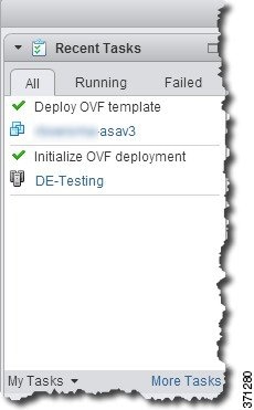
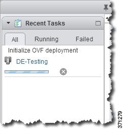
After you complete the wizard, the vSphere Web Client processes the VM; you can see the “Initialize OVF deployment” status in the Global Information area Recent Tasks pane.

When it is finished, you see the Deploy OVF Template completion status.

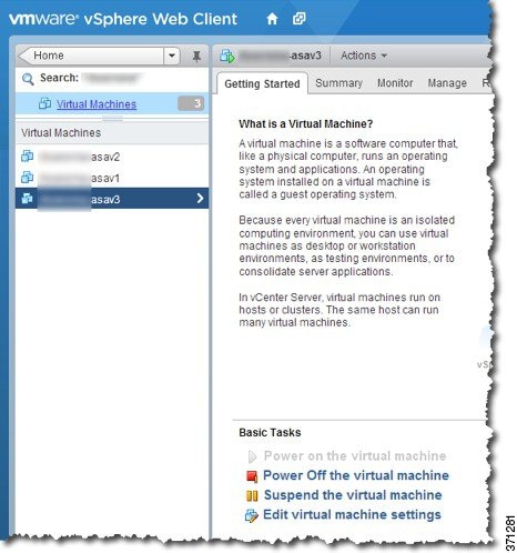
The ASA Virtual machine instance then appears under the specified data center in the Inventory.

Step 11

If the ASA Virtual machine is not yet running, click Power On the virtual machine.

Wait for the ASA Virtual to boot up before you try to connect with ASDM or to the console. When the ASA Virtual starts up for the first time, it reads parameters provided through the OVF file and adds them to the ASA Virtual system configuration. It then automatically restarts the boot process until it is up and running. This double boot process only occurs when you first deploy the ASA Virtual. To view bootup messages, access the ASA Virtual console by clicking the Console tab.

Step 12

For failover/HA deployments, repeat this procedure to add the secondary unit. See the following guidelines:

  • Set the same throughput level as the primary unit.

  • Enter the exact same IP address settings as for the primary unit. The bootstrap configurations on both units are identical except for the parameter identifying a unit as primary or secondary.


What to do next

To successfully register the ASA Virtual with the Cisco Licensing Authority, the ASA Virtual requires Internet access. You might need to perform additional configuration after deployment to achieve Internet access and successful license registration.

Deploy the ASA Virtual Using the VMware vSphere Standalone Client and Day 0 Configuration

To deploy the ASA Virtual, use the VMware vSphere Client and the open virtualization format (OVF) template file (asav-vi.ovf for a vCenter deployment or asav-esxi.ovf for a non-vCenter deployment). You use the Deploy OVF Template wizard in the vSphere Client to deploy the Cisco package for the ASA Virtual. The wizard parses the ASA Virtual OVF file, creates the virtual machine on which you will run the ASA Virtual, and installs the package.

Most of the wizard steps are standard for VMware. For additional information about the Deploy OVF Template wizard, see the VMware vSphere Client online help.

Before you begin

Procedure


Step 1

Launch the VMware vSphere Client and choose File > Deploy OVF Template.

The Deploy OVF Template wizard appears.

Step 2

Browse to the working directory where you unzipped the asav-vi.ovf file and select it.

Step 3

The OVF Template details are shown. Proceed through the following screens. You do not have to change any configuration if you choose to use a custom Day 0 configuration file.

Step 4

A summary of the deployment settings is shown in the last screen. Click Finish to deploy the VM.

Step 5

Power on the ASA Virtual, open the VMware console, and wait for the second boot.

Step 6

SSH to the ASA Virtual and complete your desired configuration. If you do not have all the configuration that you wanted in the Day 0 configuration file, open a VMware console and complete the necessary configuration.

The ASA Virtual is now fully operational.


Deploy the ASA Virtual Using the OVF Tool and Day 0 Configuration

This section describes how to deploy the ASA Virtual using the OVF tool, which requires a day 0 configuration file.

Before you begin

  • The day0.iso file is required when you are deploying the ASA Virtual using the OVF tool. You can use the default empty day0.iso file provided in the ZIP file, or you can use a customized Day 0 configuration file that you generate. See Unpack the ASA Virtual Software and Create a Day 0 Configuration File for creating a Day 0 configuration file.

  • Make sure the OVF tool is installed on a Linux or Windows PC and that it has connectivity to your target ESXi server.

Procedure


Step 1

Verify the OVF tool is installed:

Example:

linuxprompt# which ovftool

Step 2

Create a .cmd file with the desired deployment options:

Example:

linuxprompt# cat launch.cmd
ovftool \
--name="asav-941-demo" \
--powerOn \
--deploymentOption=4Core8GB \
--diskMode=thin \
--datastore=datastore1 \
--acceptAllEulas \
--net:Management0-0="Portgroup_Mgmt" \
--net:GigabitEthernet0-1="Portgroup_Inside" \
--net:GigabitEthernet0-0="Portgroup_Outside" \
--prop:HARole=Standalone \
--prop:guestinfo.day0.iso=/home/user/day0.iso \
asav-esxi.ovf \
vi://root@10.1.2.3/

Step 3

Execute the cmd file:

Example:

linuxprompt# ./launch.cmd

The ASA Virtual is powered on; wait for the second boot.

Step 4

SSH to the ASA Virtual to complete configuration as needed. If more configuration is required, open the VMware console to the ASA Virtual and apply the necessary configuration.

The ASA Virtual is now fully operational.


Deploy the ASA Virtual Unlimited on AWS

From ASA virtual version 9.24.10, you can deploy ASA Virtual Unlimited (ASAvU) on AWS.

Prerequisites

  • Create an account on aws.amazon.com.

  • License the ASA Virtual. Until you license the ASA Virtual, it will run in degraded mode, which allows only 100 connections and throughput of 100 Kbps.


    Note


    All the default license entitlements offered by Cisco, previously for ASA Virtual, will have the IPv6 configuration support.


  • Interface requirements:

    • Management interface

    • Inside and outside interfaces

    • (Optional) Additional subnet (DMZ)

  • Communications paths:

    • Management interface—Used to connect the ASA Virtual to the ASDM; can’t be used for other traffic.

    • Inside interface (required)—Used to connect the ASA Virtual to inside hosts.

    • Outside interface (required)—Used to connect the ASA Virtual to the public network.

    • DMZ interface (optional)—Used to connect the ASA Virtual to the DMZ network when using the c3.xlarge interface.

Hardware requirements

AWS ENA driver supported instance: Low-Latency Queue (LLQ) enabled. This means that LLQ mode is active on an Amazon Elastic Network Adapter (ENA). For more information on ENA and to verify if ENA is enabled, refer to Enable enhanced networking with ENA on your EC2 instances.


Note


We recommend using Nitro-v4 instance (c6in.16xlarge) for better performance.


Supported instances

Instance type

vCPUs/RAM

Applicable license

ENA queues

c6in.8xlarge

32 vCPUs / 64 GB

ASAvU

Configure default 16-queues

c6in.16xlarge

64 vCPUs / 128 GB

ASAvU

Configure default 16-queues

Configuring AWS Environment

To deploy the ASA Virtual on AWS you need to configure an Amazon VPC with your deploymentspecific requirements and settings. In most situations a setup wizard can guide you through your setup. AWS provides online documentation where you can find useful information about the services ranging from introductions to advanced features.

See https://aws.amazon.com/documentation/gettingstarted/ for more information.

Creating the VPC

A virtual private cloud (VPC) is a virtual network dedicated to your AWS account. It is logically isolated from other virtual networks in the AWS cloud. You can launch your AWS resources into your VPC. You can configure your VPC; you can select its IP address range, create subnets, and configure route tables, network gateways, and security settings.

Procedure

Step 1

Log into https://console.aws.amazon.com/ and choose your region.

AWS is divided into multiple regions that are isolated from each other. The region is displayed in the upper right corner of your screen. Resources in one region do not appear in another region. Check periodically to make sure you are in the intended region.

Step 2

On the AWS Console Home, Click View all services > VPC.

Step 3

Click VPC Dashboard > Your VPCs.

Step 4

Click Create VPC.

Step 5

Enter the following in the Create VPC dialog box:

  1. A user-defined Name tag to identify the VPC.

  2. An IPv4 CIDR block of IP addresses. CIDR (Classless Inter-Domain Routing) notation is a compact representation of an IP address and its associated routing prefix. For example, 10.0.0.0/24.

  3. A Tenancy setting of Default to ensure that instances launched in this VPC use the tenancy attribute specified at launch.

Step 6

Click Create VPC to create your VPC.


Add the Internet Gateway

You can add an Internet gateway to connect your VPC to the Internet. You can route traffic for IP addresses outside your VPC to the Internet gateway.

Before You Begin

  • Create a VPC for your ASA Virtual instances.

Procedure

Step 1

On the AWS Console Home, click View all services > VPC.

Step 2

Click VPC Dashboard > Internet Gateways, and then click Create Internet Gateway.

Step 3

Enter a user-defined Name tag to identify the gateway and click Yes, Create to create the gateway.

Step 4

Select the gateway created in the previous step.

Step 5

Click Attach to VPC and select the VPC you created previously.

Step 6

Click Attach internet gateway to attach the gateway to your VPC.

By default, the instances launched on the VPC cannot communicate with the Internet until a gateway is created and attached to the VPC.


Add subnets

You can segment the IP address range of your VPC that the ASA Virtual instances can be attached to. You can create subnets to group instances according to security and operational needs. For the ASA Virtual, you need to create a subnet for management as well as subnets for traffic.

Before You Begin

  • Create a VPC for your ASA Virtual instances.

Procedure

Step 1

On the AWS Console Home, click View all services > VPC.

Step 2

Click VPC Dashboard > Subnets, and then click Create Subnet. Select the VPC ID that you created previously.

Step 3

Enter the following in the Subnet settings dialog box:

  1. A user-defined Subnet name to identify the subnet.

  2. A VPC to use for this subnet.

  3. The Availability Zone where this subnet will reside. Select No Preference to let AWS select the zone.

  4. A CIDR block of IP addresses. The range of IP addresses in the subnet must be a subset of the range of IP addresses in the VPC. Block sizes must be between a /16 network mask and a /28 network mask. The size of the subnet can equal the size of the VPC.

Step 4

Click Create subnet to create your subnet.

Step 5

Repeat steps 2 to 4 for as many subnets required. Create a separate subnet for management traffic and create as many subnets as needed for data traffic.


Add a route table

You can attach a route table to the gateway you configured for your VPC. You can also associate multiple subnets with a single route table, but a subnet can be associated with only one route table at a time.

Procedure

Step 1

On the AWS Console Home, click View all services > VPC.

Step 2

Click VPC Dashboard > Route Tables, and then click Create route table. Enter a user-defined Name to identify the route table.

Step 3

Select the VPC that will use this route table.

Step 4

Click Create route table to create your route table. The route information is displayed in the Details pane.

Step 5

In the Routes tab, click Edit routes, and then click Add route.

  1. In the Destination column, enter 0.0.0.0/0 for IPv4 traffic.

  2. In the Target column, select the internet gateway that you created earlier.

Step 6

Click Save changes.


Create security group

You can create a security group with rules specifying allowed protocols, ports and source IP ranges. Multiple security groups can be created with different rules which you can assign to each instance.

Procedure

Step 1

On the AWS Console Home, click View all services > EC2.

Step 2

Click EC2 > Network & Security > Security Groups.

Step 3

Click Create Security Group.

Step 4

Enter the following in the Create Security Group dialog box:

  1. A user-defined Security group name to identify the security group.

  2. A Description for this security group.

  3. The VPC associated with this security group.

Step 5

Configure Inbound and Outbound rules:

  1. In the Inbound rules tab, click Add Rule to add a rule for inbound traffic with the required parameters..

    Note


    HTTPS and SSH access is required to manage the ASA Virtual from outside AWS. You should specify the Source IP addresses accordingly. Also, if you are configuring the ASA Virtual within the AWS VPC, you should allow the private IP management subnet access.

  2. In the Outbound rules tab, click Add Rule to add a rule for outbound traffic with the required parameters, or leave the defaults of All traffic (for Type) and Anywhere (for Destination).

Step 6

Click Create security group to create the security group.


Create network interfaces

You can create network interfaces for the ASA Virtual using static IP addresses or DHCP. Create network interfaces (external and internal) as needed for your particular deployment.

Procedure

Step 1

On the AWS Console Home, click View all services > EC2.

Step 2

Click EC2 > Network & Security > Network interfaces.

Step 3

Click Create Network Interface.

Step 4

Enter the following in the Create network interface window:

  1. A optional user-defined Description for the network interface.

  2. Select a Subnet from the drop-down list. Make sure to select the subnet of the VPC where you want to create the ASA Virtual instance.

  3. Enter a Private IP address. You can use a static IP address or Auto-generate (DHCP).

  4. Select one or more Security groups. Make sure the security group has all the required ports open.

Step 5

Click Create network interface to create your network interface.

Step 6

Select the network interface that you just created.

Step 7

Right-click and select Change Source/Dest. Check.

Step 8

Uncheck the Enable checkbox under Source/destination check and click Save.


Create elastic IP addresses

Elastic IP addresses are reserved public IPs that are used for remote access to the ASA Virtual as well as other instances. When an instance is created, a public IP address is associated with the instance. That public IP address changes automatically when you STOP and START the instance. To avoid this, assign a persistent public IP address to the instance using Elastic IP addressing. At a minimum, you want to create elastic IP addresses for the ASA Virtual management interface.

Procedure

Step 1

On the AWS Console Home, click View all services > EC2.

Step 2

Click EC2 > Network & Security > Elastic IPs.

Step 3

Click Allocate Elastic IP address.

Step 4

On the Allocate Elastic IP address settings dialog box, verify the settings and click Allocate to create the elastic IP address

Step 5

Repeat steps 3-4 for as many elastic IP addresses as required for your deployment.


Deploy the ASA Virtual Unlimited on AWS

Before you begin

Cisco recommends the following:

  • Ensure that the AWS VPC and EC2 elements are configured.

  • Confirm that an AMI is available on the AWS Marketplace for the ASA Virtual instances.

Procedure


Step 1

Go to the AWS Marketplace and sign in.

Step 2

After you log in, search for either Cisco Secure Firewall ASA Virtual – BYOL or Cisco Secure Firewall ASA Virtual - PAYG based on your requirement. Click View Purchase Options after selecting the required ASA Virtual. Then, click Subscribe.

Step 3

Click Launch your software.

Step 4

Choose Amazon EC2. Then, choose Launch from EC2 Console.

Step 5

Select the required ASA Virtual Version and Region.

Step 6

Click Launch from EC2. The Launch an instance window comes up.

Step 7

Enter the Name and tags details.

Step 8

Verify the details in the Application and OS Images window.

Step 9

Select the Instance type from the drop-down list.

Step 10

In the Key pair section, click Create new key pair and enter the Key pair name.

Step 11

Click Create key pair. The .pem key pair file is downloaded.

Step 12

In the Network settings section, click Edit.

Step 13

Choose the required VPC and Subnet from the drop-down lists.

Step 14

From the Auto-assign public IP drop-down list, choose Enable.

Step 15

Choose Select existing security group and choose the previously configured security group, or create a new security group. See AWS documentation for more information on creating security groups.

Step 16

Configure Storage. You can use the default values.

Step 17

Under Advanced Details, enter day-0 configuration data in the User data - optional box. CAUTION: Use only plain text when entering data in the Advanced Details field. If you copy this information from a text editor, make sure you copy only as plain text. If you copy any Unicode data into the Advanced Details field, including white space, the instance may be corrupted and you will have to terminate the instance and re-create it.

  • Management interface: If you choose to provide the Day 0 configuration details, you must provide management interface details, which should be configured to use DHCP.

  • Data interfaces: IP addresses for the data interfaces will be assigned and configured only if you provide that information as part of the Day 0 configuration. Data interfaces can be configured to use DHCP, or if the network interfaces to be attached are already created and the IP addresses that are known, you can provide the IP address details in the Day 0 configuration.

  • Without day-0 configuration: If you deploy the ASA Virtual without providing the Day 0 configuration, ASA Virtual applies the default ASA Virtual configuration where it fetches the IP addresses of the attached interfaces from the AWS metadata server and allocates the IP addresses (the data interfaces get the IP addresses assigned but the ENIs will be down). The Management0/0 interface will be up and gets the IP address configured with the DHCP address. See IP Addressing in your VPC for information about Amazon EC2 and AWS VPC IP addressing.

Example: Sample day-0 configuration for the ASA virtual.


! ASA Version 9.xx
!
interface management0/0
management-only
nameif management
security-level 100
ip address dhcp setroute

ipv6 enable
ipv6 address dhcp default
no shutdown
!
!
GWLB facing VTEP interface
interface TenGigabitEthernet0/0
nameif data-interface-in
security-level 100
ip address dhcp
no shut
!
Internet-facing outside interface
interface TenGigabitEthernet0/1
nameif data-interface-out
security-level 0
ip address dhcp
no shut
nve 1
encapsulation geneve
source-interface data-interface-in
interface vni1
proxy dual-arm
nameif vni-in
security-level 0
vtep-nve 1
! NAT for internet-bound traffic
nat (vni-in, data-interface-out) source dynamic any interface
!Default route to internet gateway= 10.1.200.1 (Outside gateway)
!Route East-West traffic (Application subnet CIDR) back to vni interface
(U-turn)
route data-interface-out 0.0.0.0 0.0.0.0 10.1.200.1
route vni-in 192.168.1.0 255.255.255.0 10.1.100.1 1
!
mtu data-interface-in 1826
jumbo-frame reservation
same-security-traffic permit inter-interface
same-security-traffic permit intra-interface
crypto key generate rsa modulus 2048
ssh 0 0 management
ssh ::/0 management
ssh timeout 60
ssh version 2
username admin password Q1w2e3r4 privilege 15
username admin attributes
service-type admin
aaa authentication ssh console LOCAL
!
same-security-traffic permit inter-interface
same-security-traffic permit intra-interface
access-list allow-all extended permit ip any any
access-list allow-all extended permit ip any6 any6
access-group allow-all global
!
interface G0/0
nameif outside
ip address dhcp setroute
ipv6 enable
ipv6 address dhcp default
no shutdown
!
interface G0/1
nameif inside
ip address dhcp
ipv6 enable
ipv6 address dhcp default
no shutdown
!

!
interface management0/0
management-only
nameif management
security-level 100
ip address dhcp setroute
no shut
!
same-security-traffic permit inter-interface
same-security-traffic permit intra-interface
!
crypto key generate rsa modulus 2048 noconfirm
ssh 0 0 management
ssh timeout 60
ssh version 2
username admin password <password> privilege 15
username admin attributes
service-type admin
enable password admin
access-list allow-all extended permit ip any any
access-group allow-all global
http server enable
http 0.0.0.0 0.0.0.0 management
access-list all extended permit ip any any
access-list out standard permit any4
same-security-traffic permit inter-interface
same-security-traffic permit intra-interface
access-group all global
call-home
profile License
destination transport-method http
destination address http https://tools.cisco.com/its/service/oddce/services/DDCEService
dns domain-lookup management
DNS server-group DefaultDNS
domain-name <domain_name>
name-server <primary_dns> management
name-server <secondary_dns> management
license smart
feature tier standard
throughput level unlimited
transport url https://smartreceiver.cisco.com/licservice/license
show license all | i Status
debug menu license 25 production
license smart register idtoken <token>

Step 18

Click Launch instance. A success banner is displayed after the instance is launched successfully.

Step 19

Go to the AWS Console Home and click View All Services > EC2 > Network & Security > Network Interfaces.

Step 20

Find the traffic interfaces previously created, then click Attach.

Step 21

Go to the AWS Console Home and click View All Services > EC2 > Instances > Instances.

Step 22

Right-click the Instance ID, and select Monitor and troubleshoot > Get system log to view the status.

Note


There will possibly be a warning of a connectivity issue. This is expected, since the eth0 interface will not be active until the EULA is completed.