NAT fundamentals and DIA

Configure NAT

Cisco IOS XE Catalyst SD-WAN includes the following types of Network Address Translation (NAT) configuration:

  • NAT Direct Internet Access (DIA): Allows remote sites to route traffic directly to the internet rather than routing the traffic to a central site or data center.

  • NAT service-side: Allows you to configure inside and outside NAT on data traffic traveling to and from the service hosts of the network overlay. Service-side NAT translates data traffic, of inside and outside host addresses, that match a configured centralized data policy.

NAT is designed for IP address conservation. NAT enables private IP networks that use nonregistered IP addresses to connect to the internet. NAT operates on a device, usually connecting two networks. Before packets are forwarded onto another network, NAT translates the private (not globally unique) addresses in the internal network into legal addresses.

NAT allows a single device to act as an agent between the internet (or public network) and a local network (or private network), which means that only a single unique IP address is required to represent an entire group of computers to anything outside their network.


Note


When NAT performs maintenance operations, it needs to lock the NAT database. When the NAT database is locked, NAT does not process any packets for translations. Typically, NAT maintenance operations are less than a second to a few seconds. Usually, NAT sending out untranslated packets is not an issue because these packets are dropped by an ISP.

Configure the following command to ensure that NAT drops packets when performing NAT database updates:

ip nat service modify-in-progress drop

NAT Direct Internet Access

Table 1. Feature History

Feature Name

Release Information

Description

Support for NAT Pool, Static NAT, and NAT as a Loopback Interface

Cisco IOS XE Catalyst SD-WAN Release 17.2.1r

Cisco vManage 20.1.1

This feature supports NAT configuration for loopback interface addresses, NAT pool support for Direct Internet Access (DIA), and static NAT.

Advertise NAT Routes Through OMP

Cisco IOS XE Catalyst SD-WAN Release 17.5.1a

This feature allows you to advertise NAT routes through the Cisco Catalyst SD-WAN Overlay Management Protocol (OMP) to the branch routers. You can configure this feature only through a Cisco SD-WAN Manager device CLI template.

Support for NAT DIA IPv4 over an IPv6 Tunnel

Cisco IOS XE Catalyst SD-WAN Release 17.8.1a

Cisco vManage Release 20.8.1

This feature provides support for an IPv4 client to access IPv4 servers when using an IPv6 network.

IPv4 traffic is routed to the internet over an IPv6 tunnel.

You can configure NAT DIA IPv4 over an IPv6 tunnel using the CLI or a CLI add-on template.

Support for PPP Dialer Interfaces with NAT DIA

Cisco IOS XE Catalyst SD-WAN Release 17.9.1a

Cisco vManage Release 20.9.1

This feature adds support for the following Point-to-Point Protocol (PPP) dialer interfaces: PPP over Ethernet (PPPoE), PPP over Asynchronous Transfer Mode (PPPoA), and PPP over Ethernet Asynchronous Transfer Mode (PPPoEoA).

You can use the PPP dialer interfaces to access IPv4 services and sites.

ALG Support for NAT DIA and Zone-Based Firewalls

Cisco IOS XE Catalyst SD-WAN Release 17.9.1a

Cisco vManage Release 20.9.1

This feature provides support for an application-level gateway (ALG) that translates the IP address inside the payload of an application packet. Specific protocols such as Domain Name System (DNS), FTP, and Session Initiation Protocol (SIP) require a NAT ALG for translation of the IP addresses and port numbers in the packet payload.

Support for Port Forwarding with NAT DIA

Cisco IOS XE Catalyst SD-WAN Release 17.9.1a

Cisco vManage Release 20.9.1

With this feature, you can define one or more port-forwarding rules to send packets received on a particular port from an external network to reach devices on an internal network.

Before Cisco IOS XE Catalyst SD-WAN Release 17.9.1a and Cisco vManage Release 20.9.1, port forwarding was available for service-side NAT only.

Support for NAT High-Speed Logging

Cisco IOS XE Catalyst SD-WAN Release 17.9.1a

Cisco vManage Release 20.9.1

—

Also

Cisco IOS XE Release 17.6.4 and later 17.6.x releases

Cisco vManage Release 20.6.4 and later 20.6.x releases

This feature provides the ability to enable or disable high-speed logging (HSL) of all translations by NAT.

You can configure NAT HSL using a device CLI template or CLI add-on feature template.

Support for Source Port Preservation for well-known Cisco Catalyst SD-WAN Ports

Cisco IOS XE Catalyst SD-WAN Release 17.10.1a

Cisco vManage Release 20.10.1

This feature allows preservation of well-known Cisco Catalyst SD-WAN ports during NAT.

Destination NAT Support

Cisco IOS XE Catalyst SD-WAN Release 17.11.1a

Cisco vManage Release 20.11.1

This feature changes the destination address of packets passing through WAN edge devices. Destination NAT is used to redirect traffic destined to a private address to the translated destination public IP address.

Port Forwarding with NAT DIA Using a Loopback Interface

Cisco IOS XE Catalyst SD-WAN Release 17.11.1a

Cisco vManage Release 20.11.1

This feature supports port forwarding with NAT DIA by using a loopback interface.

You can configure a loopback interface by using either device CLI templates or CLI add-on feature templates.

ALG Support Enhancement for NAT DIA and Zone-Based Firewalls

Cisco IOS XE Catalyst SD-WAN Release 17.11.1a

Cisco vManage Release 20.11.1

The ALG support for NAT DIA is extended for the following protocols:

  • Trivial File Transfer Protocol (TFTP)

  • Point-to-Point Tunneling Protocol (PPTP)

  • Sun Remote Procedure Call (SUNRPC)

  • Skinny Client Control Protocol (SCCP)

  • H.323

Support for Configuring Multiple NAT Types

Cisco IOS XE Catalyst SD-WAN Release 17.14.1a

Cisco Catalyst SD-WAN Manager Release 20.14.1

This feature supports configuration of multiple NAT types—interface, loopback interface, or NAT pool for Direct Internet Access (DIA).

Use the centralized data policy to assign rules for combining various NAT types for DIA traffic egressing the edge router. You can also bypass NAT altogether.

Information About NAT DIA

NAT DIA allows branch sites to route traffic directly to the internet rather than having to go through a central site to be inspected. This allows cloud-based applications to go directly to the internet and to cloud-service providers without having to use unnecessary bandwidth.

NAT DIA Flow-Stickiness

Minimum supported releases: Cisco IOS XE Release 17.6.1a, Cisco vManage Release 20.6.1

When NAT DIA is configured with centralized data policy with application match, the application flows subject to NAT DIA policy may get reset due to path change. For example, when you have a data policy matching an application list and the action is NAT DIA, the first few packets may not be identified by deep packet inspection (DPI). So, the packets not matching NAT DIA application policy follow routing to the Cisco Catalyst SD-WAN overlay path. When the flow is identified, the later packets of the flow will take the NAT DIA path as defined by the data policy. This path change results in a flow reset as different paths means different client source or port combination towards the server and the server resets the unknown TCP flows.

The Flow-Stickiness feature is enabled to record the flow level state of the NAT path. If the first packet of the flow is non-NAT, it keeps the rest of the packets of this flow to non-NAT paths. If the first packet flow is via the NAT DIA path, it keeps the rest of the packets of this flow to the NAT DIA path. It is enabled by default with NAT DIA data policy.

To disable flow stickiness, use the command flow-stickiness-disable under the localized policy using CLI add-on template.

Multiple NAT DIA Methods on an Interface

Minimum supported releases: Cisco IOS XE Catalyst SD-WAN Release 17.14.1a and Cisco Catalyst SD-WAN Manager Release 20.14.1

A NAT configuration can include an interface overload, an interface DIA pool, or an interface loopback. Having the ability to allow multiple NAT pools for an interface while also having a default interface for any traffic that doesn't match a pool provides a robust option for configuring NAT DIA.You can configure Cisco IOS XE Catalyst SD-WAN devices so that the NAT DIA traffic from an internal subnet is assigned to one public IP address, while all other NAT DIA traffic falls back to a default interface.

For example, your organization might have a requirement to apply NAT to IPs of a certain subset of phones to a different public address than the majority of internet traffic. You might also want to use public cloud services for voice and require all traffic for a voice subnet to use specific IP addresses. These scenarios require you to have multiple NAT pools for specific DIA traffic while also having a default NAT interface for regular traffic.

You can configure multiple NAT DIA methods using CLI commands, feature templates, or configuration groups. After configuring the interface with multiple NAT types, configure the centralized traffic policy to create rules based on the match–action condition. Based on the configured policy match condition and the exit DIA interface that you specify, the policy chooses the appropriate NAT method for source address translation.

If multiple NAT DIA methods are present, traffic can exit on any DIA interface and the corresponding NAT type is chosen. To ensure traffic egresses through a particular NAT DIA interface, configure the centralized traffic policy to include Local TLOC option and assign a preferred TLOC color to the NAT DIA interface. Based on the match condition, the policy selects the DIA interface associated with preferred color for egress.


Note


  • This feature supports only IPv4 addresses.

  • For a given match condition (sequence in data policy), multiple source DIA interfaces or source DIA pools can’t correspond to the same match interface. However, they can be provided in different sequences. For example, if the default NAT type is interface overload then the second method (match-interface) for the same interface cannot be interface overload. However, the second method can be a NAT pool or a loopback interface.


Benefits of NAT DIA

  • Enables good application performance

  • Contributes to reduced bandwidth consumption and latency

  • Contributes to lower bandwidth cost

  • Enables improved branch office user experience by providing DIA at remote sites

Restrictions for NAT DIA

  • NAT64:

    • NAT DIA pool is not supported for NAT64.

  • Multiple NAT DIA:

    • Support for multiple NAT DIA pools per interface requires Cisco IOS XE Catalyst SD-WAN Release 17.14.1a or later.

  • Multiple NAT mappings:

    • A NAT mapping can include an interface overload, an interface DIA pool, or an interface loopback. Multiple NAT mappings for the same interface require Cisco IOS XE Catalyst SD-WAN Release 17.14.1a or later.

    • The VPN redundancy mapping should match NAT DIA pool redundancy mapping model or provide an option on Cisco SD-WAN Manager to accept redundancy number as input field, so that the correct VPN mapping is used for NAT DIA.

  • Shared IP address:

    • An IP address used in a NAT pool cannot be shared with an interface address or static address mappings.

  • Requirement of at least one NAT on WAN interface:

    • Cisco SD-WAN Manager does not configure a NAT DIA route in a Cisco VPN template, which is the service-side VPN, if at least one form of NAT is not enabled on the WAN interface.

  • Non-tunnel traffic

    • NAT DIA or non-tunnel traffic is not supported for L3 TLOC extension.

  • Port allocation limit

    • When configuring NAT DIA for a single IP address, approximately 55,000 ports can be translated for TCP and UDP protocols each, providing up to 110,000 port translations in total.

    • When configuring NAT DIA for multiple IP addresses (NAT pool), approximately 64,000 ports can be translated for TCP and UDP protocols for each IP address in the pool. IP addresses from the NAT pool are chosen randomly and are not based on a round-robin method.

  • NAT determines the exit interface for a packet based on the best path selection for each packet individually. After selecting the exit interface, NAT uses the NAT mapping linked to that interface to choose the source IP for translation and establishes a session for that flow. All subsequent packets in the same flow exiting via the same interface use this NAT session for translation. If the interface undergoes UP or DOWN state changes, the best path selection changes, causing packets to exit through a different interface.

  • NAT translation is created for DIA traffic even when a zone-based firewall (ZBFW) feature drops traffic.

Configure NAT DIA

Workflow for Enabling NAT DIA

  1. Enable NAT by editing an existing Cisco VPN Interface Ethernet template. From Cisco IOS XE Catalyst SD-WAN Release 17.14.1a, you can configure multiple NAT types for an interface.

    1. Configure interface overload (default).


      Note


      From Cisco IOS XE Catalyst SD-WAN Release 17.14.1a, the first NAT type that you configure becomes the default or the primary NAT method for the Cisco VPN Interface Ethernet. It can be either an interface overload, NAT pool, or a loopback interface.

      Any additional NAT types that you configure for that interface become secondary NAT methods.


    2. Configure a NAT pool.

    3. Configure a loopback interface.

    4. (Optional) Configure static NAT.

  2. Configure a NAT DIA route using a Cisco VPN template, which is a service-side VPN template used to direct user traffic from a service VPN directly into the internet transport.

Configure a NAT Pool and a Loopback Interface

A NAT pool is a range of IPv4 addresses that are allocated for NAT translation as needed.

You can specify a software-only interface called a loopback interface to emulate a physical interface. A loopback interface is a virtual interface on a device that remains up (active) until you disable it. From Cisco IOS XE Catalyst SD-WAN Release 17.14.1a, you can configure multiple NAT types for an interface.

Configure NAT DIA Using Configuration Groups
  1. From the Cisco SD-WAN Manager menu, choose Configuration > Configuration Groups.

  2. Click … adjacent to the configuration group name and choose Edit.

  3. Click Transport & Management Profile.

  4. Edit the VPN0 feature by clicking … under Actions.

  5. Click Add Sub-Feature and choose Ethernet Interface.

  6. Click NAT.

  7. Click IPv4 Settings.

  8. In the NAT drop-down list, change the scope from Default to Global, and click On to enable NAT.

  9. Configure the NAT Type by choosing from one of the following options:

    • interface

    • pool

    • loopback

    From Cisco IOS XE Catalyst SD-WAN Release 17.14.1a, click Add Multiple NAT to configure more NAT pools.

    The default is the Interface option.

  10. In the NAT Type field, click the Pool option and enter the following NAT pool parameters:

    Table 2. NAT Pool Parameters

    Parameter Name

    Description

    Range Start

    Enter a starting IP address for the NAT pool.

    1. Change the scope from Default to Global to enable the field.

    2. Enter the starting IP address for the NAT pool.

    Range End

    Enter a closing IP address for the NAT pool.

    1. Change the scope from Default to Global to enable the field.

    2. Enter the last IP address for the NAT pool.

    Prefix Length

    Enter the NAT pool prefix length.

    UDP Timeout

    Enter the time when NAT translations over UDP sessions time out.

    Range: 1 to 8947 minutes

    Default: 1 minute

    TCP Timeout

    Enter the time when NAT translations over TCP sessions time out.

    Range: 1 to 8947 minutes

    Default: 60 minutes (1 hour)

  11. Configure a loopback interface. From Cisco IOS XE Catalyst SD-WAN Release 17.14.1a, click Add Multiple NAT to configure multiple loopback interfaces.

    In the NAT Type field, click the Loopback option and enter the name of the loopback interface.


    Note


    For a given match condition (sequence in data-policy), multiple source DIA interfaces or source DIA pools can’t correspond to the same match interface. However, they can be provided in different sequences. For example, if the default NAT type is interface overload then the second method (match-interface) for the same interface cannot be interface overload. However, the second method can be a NAT pool or a loopback interface.


  12. Click Save.

Configure Match and Action Parameters Using a Policy Group

After you have configured the multiple NAT types using configuration groups, configure the Application & Priority SLA policy to apply match-action conditions. When the NAT DIA traffic matches the conditions in the match portion of a centralized data policy, the packet is accepted. Then, you can associate action parameters with accepted packets.

  1. From the Cisco SD-WAN Manager menu, choose Configuration > Policy Groups > Application & Priority SLA.

  2. Click … adjacent to the policy group name and choose Edit.

  3. Click the Advanced Layout button on the top-right corner of the page to swtich to the advanced view.

  4. Click Add Traffic Policy, provide the details for the new traffic policy, and choose Accept.

  5. Click Add.

  6. Click Add Rules and enter a name and sequence for the traffic.

  7. Click Add Match to associate a match condition with the rule.

  8. Click Add Action and choose NAT VPN to associate a NAT DIA action with the match condition specified in the previous step.

    • DIA Pool: Enter a comma-separated list of NAT DIA pools. You can enter up to 4095 NAT pools.

    • DIA Interface: Enter a comma-separated list of NAT DIA interfaces.

    • ByPass: Traffic exits the DIA interface associated with public internet without applying NAT to the source IP address.

Configure NAT DIA Using a Feature Template
  1. From the Cisco SD-WAN Manager menu, choose Configuration > Templates.

  2. Click Feature Templates.


    Note


    In Cisco vManage Release 20.7.x and earlier releases, Feature Templates is titled Feature.


  3. To edit a Cisco VPN Interface Ethernet template, click … adjacent to the template name and choose Edit.

  4. Click NAT.

  5. Click IPv4.

  6. In the NAT drop-down list, change the scope from Default to Global, and click On to enable NAT.

  7. Configure interface overload.

    In the NAT Type field, ensure that Interface is enabled for interface overload mode.

    The default is the Interface option.

  8. Configure a NAT pool. From Cisco IOS XE Catalyst SD-WAN Release 17.14.1a, click Add Multiple NAT to configure more NAT pools.

    In the NAT Type field, click the Pool option and enter the following NAT pool parameters:

    Table 3. NAT Pool Parameters

    Parameter Name

    Description

    NAT Pool Range Start

    Enter a starting IP address for the NAT pool.

    1. Change the scope from Default to Global to enable the field.

    2. Enter the starting IP address for the NAT pool.

    NAT Pool Range End

    Enter a closing IP address for the NAT pool.

    1. Change the scope from Default to Global to enable the field.

    2. Enter the last IP address for the NAT pool.

    NAT Pool Prefix Length

    Enter the NAT pool prefix length.

    Overload

    Click On to enable per-port translation. The default is On.

    Note


    If Overload is set to Off, only dynamic NAT is configured on the end device. Per-port NAT is not configured.

    UDP Timeout

    Enter the time when NAT translations over UDP sessions time out.

    Range: 1 to 8947 minutes

    Default: 1 minute

    TCP Timeout

    Enter the time when NAT translations over TCP sessions time out.

    Range: 1 to 8947 minutes

    Default: 60 minutes (1 hour)

  9. Configure a loopback interface. From Cisco IOS XE Catalyst SD-WAN Release 17.14.1a, click Add Multiple NAT to configure multiple loopback interfaces.

    In the NAT Type field, click the Loopback option and enter the following values:

    Table 4. NAT Loopback Parameters

    Parameter

    Description

    NAT Inside Source Loopback Interface Specify the IP address of the loopback interface.
    UDP Timeout Enter the time when NAT translations over UDP sessions time out.

    Default: 1 minute. Range: 1-65536 minutes

    TCP Timeout Enter the time when NAT translations over TCP sessions time out.

    Default: 60 minutes (1 hour). Range: 1-65536 minutes


    Note


    When a device from one template with a NAT configuration on one virtual interface is moved to another template without NAT configuration on another virtual interface, you must first disable the NAT configurations and then remove the virtual interface before enabling NAT configurations again. You disable NAT in the template to which the device was attached initially.


  10. Click Update.

Configure Match and Action Parameters Using the Centralized Data Policy

After you have configured the multiple NAT types using a feature template, configure the traffic rules in the centralized data policy to apply match-action conditions. When the NAT DIA traffic matches the conditions in the match portion of a centralized data policy, the packet is accepted. Then, you can associate action parameters with accepted packets. For more information, about configuring the traffic policy, see Configure Traffic Rules in the Cisco Catalyst SD-WAN Policies Configuration Guide . After you have created a traffic policy, specify the match and action conditions:

  1. Configure the traffic data policy.

  2. After creating a custom sequence type in the traffic data policy, click Sequence Rule and configure the the details for the new traffic policy and choose Accept.

  3. Configure the match condition. For more information, see Match Parameters - Data Policy in the Cisco Catalyst SD-WAN Policies Configuration Guide.

  4. Click Actions > Accept.

  5. Click NAT VPN and choose from the following NAT DIA actions to associate with the match condition that you specify in the previous step:

    • ByPass: Traffic exits the DIA interface associated with public internet without applying NAT to the source IP address.

    • Pool: Enter a comma-separated list of NAT DIA pools. You can enter up to 4095 NAT pools.

    • Interface: Enter a comma-separated list of NAT DIA interfaces. You can enter up to four interfaces.

Configure Multiple NAT Types Using CLI

Minimum supported releases: Cisco IOS XE Catalyst SD-WAN Release 17.14.1a and Cisco Catalyst SD-WAN Manager Release 20.14.1

  1. Configure a NAT DIA interface.

    interface interface-name
     ip address ip-address prefix/length
     no ip redirects
     load-interval interval-number
     negotiation auto
     ip nat outside
     !
  2. Configure multiple NAT DIA methods where the default NAT method is a NAT pool and the alternative or secondary NAT method is an interface overload.

    ip nat inside source list list-name pool pool-name overload egress-interface interface-name
  3. Configure the alternative or secondary NAT method by using the match-interface keyword. Here, the alternative or secondary NAT method is the interface overload.

    ip nat inside source list list-name interface interface-name overload match-interface interface-name

    For more information about the match-interface keyword, see the ip nat inside source command in the Cisco Catalyst SD-WAN Qualified Command Reference guide.

The following is a sample configuration for configuring multiple NAT DIA where the default NAT method is using a NAT pool and the alternative or secondary NAT method is using interface overload with match-interface:

interface GigabitEthernet1
 ip address 10.1.1.1 255.255.255.0
 no ip redirects
 load-interval 30
 negotiation auto
 ip nat outside
 !
 ip nat inside source list dia-list pool natpool1 overload egress-interface GigabitEthernet1
 ip nat inside source list dia-list interface GigabitEthernet1 overload match-interface GigabitEthernet1

The following is an example for configuring loopback interfaces as alternative or secondary NAT methods while the default method is a NAT pool or interface overload:

interface GigabitEthernet1
 ip address 10.1.1.1
 no ip redirects
 load-interval 30
 negotiation auto
 ip nat outside
 !
 ip nat inside source list dia-list interface Loopback10 overload match-interface GigabitEthernet1
 ip nat inside source list dia-list interface Loopback11 overload match-interface GigabitEthernet1

The following is an example for configuring NAT pools as alternative or secondary methods while the default method is an interface overload or a NAT pool:

interface GigabitEthernet1
 ip address 10.1.1.1
 no ip redirects
 load-interval 30
 negotiation auto
 ip nat outside
 !
 ip nat pool natpool10 10.10.10.10 10.10.10.10 prefix-length 24 
 ip nat inside source list dia-list pool natpool1 overload match-interface GigabitEthernet1
 ip nat inside source list dia-list pool natpool2 overload match-interface GigabitEthernet1
Configure the Traffic Data Policy

After you have configured the multiple NAT types using a feature template, configure the traffic rules in the centralized data policy to apply match-action conditions. When the NAT DIA traffic matches the conditions in the match portion of a centralized data policy, the packet is accepted.

The following is a sample configuration for configuring the traffic data policy:

data-policy data-policy-name
  vpn-list list-name
   sequence sequence-number
    match source-data-prefix-list data-prefix list-name
    !
    action accept
     count vpn-list-name
     nat use-vpn 0
     nat source-dia-pool pool-id
     nat source-dia-interface interface-name
    !
   !
   default-action drop
  !

The following is an example for configuring the traffic data policy:

data-policy MULTIPLE-NAT-DIA-TRAFFIC
  vpn-list VPN1
   sequence 1
    match source-data-prefix-list NAT-DIA-PREFIX-LIST
    !
    action accept
     count VPN1-TRAFFIC
     nat use-vpn 0
     nat source-dia-pool 1
         !
   !
   default-action drop
  !

For more information about configuring the traffic data policy, see Configure Centralized Policies Using the CLI in Cisco Catalyst SD-WAN Policies Configuration Guide.

The following is an example configuration corresponding to the above traffic data policy, where the default NAT method is interface overload and the alternative or secondary NAT method is NAT pool:

interface GigabitEthernet1
 ip address 10.1.1.1 255.255.255.0
 no ip redirects
 load-interval 30
 negotiation auto
 ip nat outside
 !
 ip nat inside source list dia-list pool natpool1 overload match-interface GigabitEthernet1
 ip nat inside source list dia-list interface GigabitEthernet1 overload

Configure a NAT DIA Route

Every service VPN routes packets into the transport VPN for DIA traffic. Configure a NAT DIA route for the service-side VPN.


Note


You configure an IPv4 DIA route in a Cisco VPN template, which is a service-side VPN.


Configure a NAT DIA Route Using a Cisco VPN Template
  1. From the Cisco SD-WAN Manager menu, choose Configuration > Templates.

  2. Click Feature Templates.


    Note


    In Cisco vManage Release 20.7.x and earlier releases, Feature Templates is titled Feature.


  3. To edit a Cisco VPN template, click . . . adjacent to the template name and choose Edit.

  4. Click IPv4 Route.

  5. Click New IPv4 Route.

  6. In the Prefix field, enter an IPv4 prefix for NAT.

  7. In the Gateway field, click VPN.

  8. In the Enable VPN drop-down list, change the scope from Default to Global, and click On to enable VPN.

  9. Click Update.

Configure a NAT DIA Route Using the CLI

The following is a sample configuration for configuring a NAT DIA route.

Device(config)# interface GigabitEthernet3
ip address 192.0.2.1 255.255.255.0
ip nat outside
no shut

interface GigabitEthernet2
vrf forwarding 1
ip address 10.0.0.1 255.255.255.0
no shut

ip nat route vrf 1 0.0.0.0 0.0.0.0 global
ip route 0.0.0.0 0.0.0.0 192.0.2.2

Verify NAT DIA Route Configuration

The following is a sample output from the show ip route command:

Device# show ip route
Codes: L - local, C - connected, S - static, R - RIP, M - mobile, B - BGP
       D - EIGRP, EX - EIGRP external, O - OSPF, IA - OSPF inter area 
       N1 - OSPF NSSA external type 1, N2 - OSPF NSSA external type 2
       E1 - OSPF external type 1, E2 - OSPF external type 2, m - OMP
       n - NAT, Ni - NAT inside, No - NAT outside, Nd - NAT DIA
       i - IS-IS, su - IS-IS summary, L1 - IS-IS level-1, L2 - IS-IS level-2
       ia - IS-IS inter area, * - candidate default, U - per-user static route
       H - NHRP, G - NHRP registered, g - NHRP registration summary
       o - ODR, P - periodic downloaded static route, l - LISP
       a - application route
       + - replicated route, % - next hop override, p - overrides from PfR
       & - replicated local route overrides by connected

The following is a sample output from the show ip route vrf 1 command:

Device# show ip route vrf 1

Routing Table: 1
Codes: L - local, C - connected, S - static, R - RIP, M - mobile, B - BGP
       D - EIGRP, EX - EIGRP external, O - OSPF, IA - OSPF inter area 
       N1 - OSPF NSSA external type 1, N2 - OSPF NSSA external type 2
       E1 - OSPF external type 1, E2 - OSPF external type 2, m - OMP
       n - NAT, Ni - NAT inside, No - NAT outside, Nd - NAT DIA
       i - IS-IS, su - IS-IS summary, L1 - IS-IS level-1, L2 - IS-IS level-2
       ia - IS-IS inter area, * - candidate default, U - per-user static route
       H - NHRP, G - NHRP registered, g - NHRP registration summary
       o - ODR, P - periodic downloaded static route, l - LISP
       a - application route
       + - replicated route, % - next hop override, p - overrides from PfR
       & - replicated local route overrides by connected

NAT DIA IPv4 over an IPv6 Tunnel

The following sections provide information about configuring NAT DIA IPv4 over an IPv6 tunnel.

Information About NAT DIA IPv4 over an IPv6 Tunnel

The NAT DIA IPv4 over an IPv6 tunnel enables IPv6-only devices to access IPv4 websites and services.

The traffic flow is from the service side (LAN) to the transport side (WAN) in the overlay network.

Service-side source IPv4 addresses are translated to public IPv4 addresses on the tunnel interface.

Configure NAT DIA IPv4 over an IPv6 tunnel using a device CLI or a CLI add-on template.

Benefits of NAT DIA IPv4 over an IPv6 Tunnel
  • Provides IPv4 access from an IPv6-only device.

  • Supports routing of IPv4 traffic over an IPv6 tunnel.

  • Supports translation of service-side source IPv4 addresses to public IPv4 addresses on the tunnel interface.

Restrictions for NAT DIA IPv4 over an IPv6 Tunnel

  • NAT DIA tracker is not supported.

  • Unified Threat Defense (UTD) is not supported.

  • Keepalive traffic on a tunnel interface is not supported.

Use Case for NAT DIA IPv4 over an IPv6 Tunnel

A customer has an IPv6-only device, but requires access to IPv4 websites and services. To support this scenario, use an IPv6 tunnel for directing the IPv4 traffic to the internet.

Figure 2. NAT DIA IPv4 over IPv6 Tunnel Support
NAT DIA IPv4 over IPv6 Tunnel Support

Minimum supported release: Cisco IOS XE Catalyst SD-WAN Release 17.11.1a and Cisco vManage Release 20.11.1

The border router acts as a gateway between IPv6 and IPv4 traffic to send IPv4 bound traffic through static IPv6 tunnel. When the border router and the IPv6 tunnel is unreachable, the WAN edge device cannot determine if the IPv6 tunnel is inactive and therefore cannot re-route the traffic.

Associating IPv4 DIA tracker to an IPv6 tunnel and the border router, helps the WAN edge device to determine if the IPv6 tunnel is active based on the tracker status. When IPv4 tracker is inactive, the associated IPv6 tunnel is also inactive and the traffic is re-routed to an alternative path based on the routing table. When the IPv4 tracker is active, the associated IPv6 tunnel is also active and the traffic is resumed back to the IPv6 tunnel.

Workflow for Configuring NAT DIA IPv4 over an IPv6 Tunnel

Cisco SD-WAN Manager Configuration
  1. Enable NAT by editing an existing Cisco VPN Interface Ethernet template.

    1. Configure interface overload (default).

    2. Configure a NAT pool.

  2. Configure a NAT DIA route using a Cisco VPN template.

CLI Configuration
  1. Configure an IPv4 over an IPv6 tunnel.

  2. Configure the ip nat outside command on the tunnel interface.

  3. Configure a NAT DIA route for routing IPv4 traffic over an IPv6 tunnel.

Configure NAT DIA IPv4 over an IPv6 Tunnel Using the CLI

  1. Configure a global default route for the IPv6 tunnel:

    Device(config)# interface Tunnel1000
    Device(config-if)# ip address 10.1.15.15 255.255.255.0
    Device(config-if)# ip mtu 1460
    Device(config-if)# ip tcp adjust-mss 1420
    Device(config-if)# load-interval 30
    Device(config-if)# tunnel source GigabitEthernet3
    Device(config-if)# tunnel mode ipv6
    Device(config-if)# tunnel destination 2001:DB8:A1:10::10
    Device(config-if)# tunnel route-via GigabitEthernet3 mandatory
    Device(config-if)# tunnel path-mtu-discovery
    !
    Device(config)# ip route 0.0.0.0 0.0.0.0 Tunnel1000 
  2. Configure an IPv4 over an IPv6 tunnel using the ip nat outside command:

    Device(config)# interface Tunnel1000 
    Device(config)# ip nat outside
  3. Configure an IPv4 over an IPv6 tunnel with a NAT pool and interface overload mode:

    Device(config)# interface Tunnel1000 
    Device(config)# ip nat inside source list nat-dia-vpn-hop-access-list interface Tunnel1000 overload

    or

    Device(config)# ip nat pool natpool10 203.0.113.1 203.0.113.25 prefix-length 24
    Device(config)# ip nat inside source list nat-dia-vpn-hop-access-list pool natpool10 overload egress-interface Tunnel1000
  4. Configure a NAT DIA route within a service-side VPN:

    Device(config)# ip nat route vrf 10 0.0.0.0 0.0.0.0 global

    Note


    If you are configuring a NAT DIA route using a centralized data policy, use the nat use-vpn 0 command.


Configure NAT DIA IPv4 over an IPv6 Tunnel Using CLI (Cisco IOS XE Catalyst SD-WAN Release 17.11.1a and later releases)

Minimum supported release: Cisco IOS XE Catalyst SD-WAN Release 17.11.1a and Cisco vManage Release 20.11.1


Note


By default, CLI templates execute commands in global config mode.


You can configure NAT DIA IPv4 over an IPv6 tunnel using IPv4 NAT DIA tracker.

  1. Configure the endpoint tracker for tracking the status of an endpoint:

    endpoint-tracker tracker-name

  2. Configure the IP address of an endpoint:

    endpoint-ip ip-address

  3. Configure the tracker type for the tracker:

    tracker-type interface-name

  4. Configure NAT DIA IPv4 over an IPv6 tunnel.

Here is the complete configuration example to configure NAT DIA IPv4 over an IPv6 tunnel using IPv4 DIA tracker:


       endpoint-tracker test1
        endpoint-ip 10.0.12.13
        tracker-type interface

          interface Tunnel5
          ip address 192.168.9.2 255.255.255.0
          ip nat outside
          endpoint-tracker test1
          tunnel source GigabitEthernet8
          tunnel mode ipv6
           tunnel destination 2A00:B00::1D1E:CA68
           tunnel path-mtu-discovery

           interface GigabitEthernet8
           no ip address
           negotiation auto
           ipv6 address 2A00:B00::1D1E:CA58/64
           no mop enabled
           no mop sysid

        ip nat inside source list nat-dia-vpn-hop-access-list interface Tunnel5 overload
        ip nat route vrf 1 0.0.0.0 0.0.0.0 global
        ip route 0.0.0.0 0.0.0.0 Tunnel5

Configure NAT DIA IPv4 over an IPv6 Tunnel Using a CLI Add-On Template

Before You Begin

Create a new CLI add-on template or edit an existing CLI add-on template.

Configure NAT DIA IPv4 over an IPv6 Tunnel Using a CLI Add-On Template
  1. From the Cisco SD-WAN Manager menu, choose Configuration > Templates.

  2. Click Feature Templates.

  3. Click Add Template.

  4. Choose a device from the device list.

  5. In the OTHER TEMPLATES area, click CLI Add-On Template.

  6. In the CLI Add-On Template area, enter the configuration.

  7. Configure IPv4 over an IPv6 tunnel as shown in the following example configuration:

    interface Tunnel1000
     no shutdown
     ip address 203.0.113.1 255.255.255.0
     ip nat outside
     load-interval 30
     tunnel source GigabitEthernet1
     tunnel destination 2001:DB8:A1:10::10
     tunnel mode ipv6
     tunnel path-mtu-discovery
     tunnel route-via GigabitEthernet1 mandatory
    !
    ip nat inside source list nat-dia-vpn-hop-access-list interface Tunnel1000 overload
    ip route 0.0.0.0 0.0.0.0 Tunnel1000 203.0.113.2
    ip nat route vrf 10 0.0.0.0 0.0.0.0 global
  8. Click Save.

    The CLI add-on template that you created is displayed in the CLI Configuration table.

  9. Attach the CLI add-on template to your device.

Verify NAT DIA IPv4 over an IPv6 Tunnel Configuration

Verify NAT DIA Route Entries

The following is a sample output from the show ip nat route-dia command:

Device# show ip nat route-dia 
route add [1] addr [0.0.0.0] vrfid [2] prefix len [0] 
route add [1] addr [0.0.0.0] vrfid [4] prefix len [0] 

In the sample output, two NAT route advertisements are enabled.

Verify NAT DIA Routing Table Entries

The following is a sample output from the show ip route vrf 1 nat-route command:

Device# show ip route vrf 1 nat-route 
Routing Table: 1
Codes: L - local, C - connected, S - static, R - RIP, M - mobile, B - BGP
       D - EIGRP, EX - EIGRP external, O - OSPF, IA - OSPF inter area 
       N1 - OSPF NSSA external type 1, N2 - OSPF NSSA external type 2  
       E1 - OSPF external type 1, E2 - OSPF external type 2, m - OMP 
       n - NAT, Ni - NAT inside, No - NAT outside, Nd - NAT DIA
       i - IS-IS, su - IS-IS summary, L1 - IS-IS level-1, L2 - IS-IS level-2
       ia - IS-IS inter area, * - candidate default, U - per-user static route
       H - NHRP, G - NHRP registered, g - NHRP registration summary
       o - ODR, P - periodic downloaded static route, l - LISP
       a - application route
       + - replicated route, % - next hop override, p - overrides from PfR
       & - replicated local route overrides by connected

Gateway of last resort is 0.0.0.0 to network 0.0.0.0

n*Nd  0.0.0.0/0 [6/0], 00:40:17, Null0

In this sample output, n*Nd 0.0.0.0/0 is the configured NAT DIA route.

Display IP Translations

The following is a sample output from the show ip nat translations command:

Device# show ip nat translations
show ip nat translations 
Pro  Inside global        Inside local          Outside local         Outside global
tcp  203.0.113.1:5201     10.20.24.150:5201     10.20.25.150:5201     10.20.25.150:5201
icmp 203.0.113.1:25440    10.20.24.150:25440    10.20.25.150:25440    10.20.25.150:25440
Total number of translations: 2

In the sample output, there are two translations.

Verify IP NAT Global Statistics

The following is a sample output from the show ip nat statistics command:

Device# show ip nat statistics
Total active translations: 2 (0 static, 2 dynamic; 2 extended)
Outside interfaces:
  Tunnel1000
Inside interfaces: 
Hits: 1012528  Misses: 56
Expired translations: 3
Dynamic mappings:
-- Inside Source
[Id: 3] access-list nat-dia-vpn-hop-access-list interface Tunnel1000 refcount 2
nat-limit statistics:
 max entry: max allowed 0, used 0, missed 0
In-to-out drops: 0  Out-to-in drops: 0
Pool stats drop: 0  Mapping stats drop: 0
Port block alloc fail: 0
IP alias add fail: 0
Limit entry add fail: 0

In the sample output, there are two translations for tunnel 11000.

The output of the show ip nat statistics command displays information about all the IP address pools and NAT mappings that you have configured.

Clear NAT Global Statistics

Use the clear ip nat statistics command to clear NAT global statistics:

Device# clear ip nat global statistics
Display NAT Statistics

The following is a sample output from the show platform hardware qfp active feature nat datapath stats command:

Device# show platform hardware qfp active feature nat datapath stats
Total active translations: 2 (0 static, 2 dynamic; 2 extended)
Outside interfaces:
  Tunnel1000
Inside interfaces: 
Hits: 1012528  Misses: 56
Expired translations: 3
Dynamic mappings:
-- Inside Source
[Id: 3] access-list nat-dia-vpn-hop-access-list interface Tunnel1000 refcount 2
nat-limit statistics:
 max entry: max allowed 0, used 0, missed 0
In-to-out drops: 0  Out-to-in drops: 0
Pool stats drop: 0  Mapping stats drop: 0
Port block alloc fail: 0
IP alias add fail: 0
Limit entry add fail: 0
Check NAT Global Counters: Datapath Map

The following is a sample output from the show platform hardware qfp active feature nat datapath map command:

Device# show platform hardware qfp active feature nat datapath map
I/f Map Table

if_handle 65529 next 0x0 hash_index 220
laddr 0.0.0.0 lport 0 map 0xdec942c0 refcnt 0
gaddr 203.60.10.1 gport 0 proto 0 vrfid 0x0
src_type 1 flags 0x80100 cpmapid 3
I/f Map Table End
edm maps 0
mapping id 1 pool_id 0 if_handle 0xfff9 match_type 0 source_type 1 domain 0 proto 0 Local IP 0.0.0.0, 
Local Port 0 Global IP 203.60.10.1 Global Port 0 Flags 0x80100 refcount 0 cp_mapping_id 3 
next 0x0 hashidx 50 vrfid 0 vrf_tableid 0x0 rg 0 pap_enabled 0 egress_ifh 0x14 
Check NAT Global Counters: Session Dump

The following is a sample output from the show platform hardware qfp active feature nat datapath sess-dump command:

Device# show platform hardware qfp active feature nat sess-dump
id 0xdd70c1d0 io 10.20.24.150 oo 10.20.25.150 io 5201 oo 5201 it 203.0.113.1 ot 10.20.25.150 it 5201 ot 5201 pro 6 vrf 4 tableid 4 bck 65195 in_if 0 out_if 20 ext_flags 0x1 in_pkts 183466 in_bytes 264182128 out_pkts 91731 out_bytes 2987880flowdb in2out fh 0x0 flowdb out2in fh 0x0 
id 0xdd70c090 io 10.20.24.150 oo 10.20.25.150 io 25965 oo 25965 it 203.0.113.1 ot 10.20.25.150 it 25965 ot 25965 pro 1 vrf 4 tableid 4 bck 81393 in_if 0 out_if 20 ext_flags 0x1 in_pkts 27 in_bytes 38610 out_pkts 27 out_bytes 38610flowdb in2out fh 0x0 flowdb out2in fh 0x0 

Configuration Examples for NAT DIA IPv4 over an IPv6 Tunnel

Device# show sdwan running-config | section Tunnel1000|GigabitEthernet1
interface GigabitEthernet1
 ip address 10.1.15.15 255.255.255.0
 no ip redirects
 load-interval 30
 negotiation auto
 ipv6 address 2001:DB8:A1:F::F/64
 ipv6 enable
 ipv6 nd ra suppress all
 service-policy output shape_GigabitEthernet1 
!
interface Tunnel1000
 no shutdown
 ip address 203.0.113.1 255.255.255.0
 ip nat outside
 load-interval 30
 tunnel source GigabitEthernet1
 tunnel destination 2001:DB8:a1:10::10
 tunnel mode ipv6
 tunnel path-mtu-discovery
 tunnel route-via GigabitEthernet1 mandatory
!
ip nat inside source list nat-dia-vpn-hop-access-list interface Tunnel1000 overload
ip route 0.0.0.0 0.0.0.0 Tunnel1000 203.0.113.2
ip nat route vrf 10 0.0.0.0 0.0.0.0 global

Dialer Interfaces with NAT DIA

The following sections provide information about configuring dialer interfaces with NAT DIA.

Information About Using a Dialer Interface with NAT DIA

Minimum supported releases: Cisco IOS XE Catalyst SD-WAN Release 17.9.1a, Cisco vManage Release 20.9.1

This feature provides support for Point-to-Point Protocol (PPP) dialer interfaces for the NAT DIA use case. Use dialer interfaces to access IPv4 internet services and sites.

A dialer interface specifies how to handle traffic from clients, including default routing information, the encapsulation protocol, and the dialer pool to use.

The following dialer interfaces are supported:

  • Point-to-Point Protocol over Ethernet (PPPoE)

  • Point-to-Point Protocol over Asynchronous Transfer Mode (PPPoA)

  • Point-to-Point Protocol over Ethernet over Asynchronous Transfer Mode (PPPoEoA)

Adjust the TCP Maximum Segment Size for NAT DIA

Note


Beginning with Cisco IOS XE Catalyst SD-WAN Release 17.9.1a and Cisco vManage Release 20.9.1, you can adjust the TCP maximum segment size (MSS) value for preventing dropped TCP sessions.


Benefits of Using a Dialer Interface with NAT DIA
  • Supports interface overload mode with NAT DIA

  • Supports route-based as well as data-policy-based configuration with NAT DIA

  • Provides support for NAT pools and loopback

  • Provides support for static NAT configuration

  • Provides support for static NAT port forwarding

  • Allows physical interfaces to take on different characteristics based on incoming or outgoing call requirements

  • Provides static or negotiated IP address support over a dialer interface with NAT DIA

Workflow for a NAT DIA Dialer Interface

Minimum supported releases: Cisco IOS XE Catalyst SD-WAN Release 17.9.1a, Cisco vManage Release 20.9.1

The following diagram describes how IPv4 client traffic gets routed over a dialer interface for reaching IPv4 internet sites and services.

Figure 3. Workflow for NAT DIA Dialer Interface Support
Workflow for NAT DIA Dialer Interface Support

Restrictions for Using a Dialer Interface with NAT DIA

Minimum supported releases: Cisco IOS XE Catalyst SD-WAN Release 17.9.1a, Cisco vManage Release 20.9.1

  • Only NAT DIA is supported with dialer interfaces.

  • No support for service-side NAT with dialer interfaces.

  • PPPoE jumbo frames are limited to 1800 bytes when using a device CLI or a CLI add-on template.

  • There is no support for configuring the following PPPoA dialer interface encapsulations: AAL5MUX, AAL5SNAP, AAL5NLPID, or bridge-dot1q using Cisco SD-WAN Manager feature templates. If you want to configure these PPPoA encapsulations, you need to configure the encapsulations using a CLI template.

  • NAT DIA tracker is not supported for a dialer interface with an ip unnumbered interface.

  • NAT DIA path preference is not supported with loopback on a WAN interface.

Configure a Dialer Interface with NAT DIA Using a CLI Template

Minimum supported releases: Cisco IOS XE Catalyst SD-WAN Release 17.9.1a, Cisco vManage Release 20.9.1

  1. Configure a PPPoE dialer interface with NAT DIA enabled.

    The dialer down-with-vInterface command, available from Cisco IOS XE Catalyst SD-WAN Release 17.9.1a and Cisco vManage Release 20.9.1, brings down the dialer interface when the PPP session goes down.

    interface interface-type-number
     pppoe enable group global
     pppoe-client dial-pool-number dialer-pool-number
    !
    interface Dialer dialer-number
     description interface vers le BAS
     mtu bytes
     ip address negotiated
     ip mtu bytes
     ip nat outside
     encapsulation encapsulation-type
     ip tcp adjust-mss bytes
     dialer pool dialer-pool-number
     dialer down-with-vInterface
     ppp chap hostname hostname
     ppp chap password password
     ppp authentication chap callin
     ppp ipcp route default
     service-policy output shape_Dialer dialer-number
  2. Enable ip nat outside over a dialer interface with interface overload mode.

    interface Dialer dialer-number
    ip nat outside
    ip nat inside source list nat-dia-vpn-hop-access-list interface Dialer dialer-number overload
  3. Configure a NAT DIA route for a service-side VPN.

    or

    Configure a NAT DIA route for a service-side VPN using a centralized data policy.

    ip nat route vrf vrf-id route-prefix prefix-mask global

Note


When dialer interface is deleted in the same transaction as NAT Mapping with Pool-overload-config, an extra no NAT configuration is generated. Remove each NAT configurations separately using different transactions as shown:

Device(config)# no ip nat inside source list global-list pool natpool-Dialer100-0 overload egress-interface Dialer100
Device(config)# commit
 
Device(config)# no interface Dialer100
Device(config)# commit

Here is the complete configuration example for configuring a dialer interface with NAT DIA.

interface Dialer100
 mtu 1492
 ip address negotiated
 ip nat outside
 encapsulation ppp
 ip tcp adjust-mss 1452
 dialer pool 100
 dialer down-with-vInterface
 endpoint-tracker tracker-google 
 ppp authentication chap callin
 ppp chap hostname branch1.ppp1
 ppp chap password 7 01100F175804
 ppp ipcp route default
 service-policy output shape_GigabitEthernet0/0/1
!
interface GigabitEthernet0/0/1
 no ip redirects
 pppoe enable group global
 pppoe-client dial-pool-number 100
!
sdwan
 interface Dialer100
  tunnel-interface
   encapsulation ipsec weight 1
   color mpls restrict
  exit
 exit
ip nat inside source list nat-dia-vpn-hop-access-list interface Dialer100 overload
ip nat route vrf 10 0.0.0.0 0.0.0.0 global

Verify a Dialer Interface Configuration

Minimum supported releases: Cisco IOS XE Catalyst SD-WAN Release 17.9.1a, Cisco vManage Release 20.9.1

The following sections provide information on verifying a dialer interface configuration.

Verify NAT DIA IP Route Configuration

The following is a sample output from the show ip route vrf command:

Device# show ip route vrf 10
Routing Table: 1
Codes: L - local, C - connected, S - static, R - RIP, M - mobile, B - BGP
D - EIGRP, EX - EIGRP external, O - OSPF, IA - OSPF inter area
N1 - OSPF NSSA external type 1, N2 - OSPF NSSA external type 2
E1 - OSPF external type 1, E2 - OSPF external type 2, m - OMP
n - NAT, Ni - NAT inside, No - NAT outside, Nd - NAT DIA
i - IS-IS, su - IS-IS summary, L1 - IS-IS level-1, L2 - IS-IS level-2
ia - IS-IS inter area, * - candidate default, U - per-user static route
H - NHRP, G - NHRP registered, g - NHRP registration summary
o - ODR, P - periodic downloaded static route, l - LISP
a - application route
+ - replicated route, % - next hop override, p - overrides from PfR
& - replicated local route overrides by connected

Gateway of last resort is 0.0.0.0 to network 0.0.0.0

n*Nd 0.0.0.0/0 [6/0], 4d01h, Null0
10.0.0.0/8 is variably subnetted, 3 subnets, 2 masks

In the sample output, n*Nd 0.0.0.0/0 is the configured NAT DIA route.

Verify Translation of IP Addresses

The following is a sample output from the show ip nat translations command:

Device# show ip nat translations
Pro   Inside global       Inside local        Outside local    Outside global
tcp   192.0.2.1:80        10.10.0.100:8080    ---               ---
---   192.0.2.2.198       10.10.0.254         ---               ---
tcp   192.0.2.1:8000      10.10.0.253:23      ---               ---
tcp   192.0.2.25:25185    10.0.0.1:43878      203.0.113.1:80    203.0.113.1:80
tcp   192.0.2.3:48871     10.0.0.2:48871      203.0.113.2:80    203.0.113.2:80
tcp   192.0.2.3:63242     10.0.0.2:63242      203.0.113.2:80    203.0.113.2:80
tcp   192.0.2.3:52929     10.0.0.2:52929      203.0.113.2:80    203.0.113.2:80
tcp   192.0.2.4:25184     10.0.0.4:28456      203.0.113.1:80    203.0.113.1:80
udp   192.0.2.3:64681     10.0.0.2:64681      203.0.113.1:53    203.0.113.1:53
udp   192.0.2.3:65504     10.0.0.2:64670      203.0.113.1:53    203.0.113.1:53
tcp   192.0.2.25:25186    10.0.0.1:28455      203.0.113.1:80    203.0.113.1:80
Total number of translations: 11

In the sample output, there are 11 translations.

Display Your PPPoE Sessions

The following is a sample output from the show pppoe session command:

Device# show pppoe session
     1 client session 

Uniq ID  PPPoE  RemMAC          Port                    VT  VA         State
           SID  LocMAC                                      VA-st      Type
    N/A    391  84b2.61cc.9903  Gi0/0/1.100           Di100 Vi2        UP      
                c884.a1f4.b981  VLAN: 100                   UP 

In this sample output, the PPPoE dialer interface displays as UP.

The following is a sample output from the show ppp all command:

Device# show ppp all
Interface/ID OPEN+ Nego* Fail-     Stage    Peer Address    Peer Name
------------ --------------------- -------- --------------- --------------------
Vi2          LCP+ IPCP+ CDPCP-     LocalT   172.16.100.1    SDWAN-AGGREGE   
Verify PPP Negotiation Information

The following is a sample output from the show interfaces Dialer command:

Device# show interfaces Dialer100
Dialer100 is up, line protocol is up 
  Hardware is Unknown
  Internet address is 172.16.100.101/32
  MTU 1492 bytes, BW 56 Kbit/sec, DLY 20000 usec, 
     reliability 255/255, txload 255/255, rxload 255/255
  Encapsulation PPP, LCP Closed, loopback not set
  Keepalive set (10 sec)
  DTR is pulsed for 1 seconds on reset
  Interface is bound to Vi2
  Last input 00:09:05, output 00:00:09, output hang never
  Last clearing of "show interface" counters 1w0d
  Input queue: 0/375/0/0 (size/max/drops/flushes); Total output drops: 0
  Queueing strategy: weighted fair
  Output queue: 0/1000/64/0 (size/max total/threshold/drops) 
     Conversations  0/0/16 (active/max active/max total)
     Reserved Conversations 0/0 (allocated/max allocated)
     Available Bandwidth 56 kilobits/sec
  5 minute input rate 42220429000 bits/sec, 23 packets/sec
  5 minute output rate 1520154000 bits/sec, 23 packets/sec
     755339342 packets input, 2706571669546067 bytes
     696497150 packets output, 97523835049377 bytes
Bound to:
Virtual-Access2 is up, line protocol is up 
  Hardware is Virtual Access interface
  Internet address will be negotiated using IPCP
  MTU 1492 bytes, BW 56 Kbit/sec, DLY 20000 usec, 
     reliability 255/255, txload 177/255, rxload 177/255
  Encapsulation PPP, LCP Open
  Stopped: CDPCP
  Open: IPCP

In this sample output, Dialer100 is up and the line protocol is up. Virtual-Access2 is also up and the line protocol is up.

Configuration Example for Using a Dialer Interface with NAT DIA

Minimum supported releases: Cisco IOS XE Catalyst SD-WAN Release 17.9.1a, Cisco vManage Release 20.9.1

This example shows the configuration of a dialer interface with a NAT pool, inside static NAT, and port forwarding.

ip nat pool natpool10 203.0.113.1 203.0.113.25 prefix-length 24
ip nat inside source list nat-dia-vpn-hop-access-list interface Dialer100 overload
ip nat inside source list nat-dia-vpn-hop-access-list pool natpool10 overload
egress-interface Dialer100
ip nat inside source static 10.10.80.254 10.1.1.198 vrf 10 egress-interface Dialer100
ip nat inside source static tcp 10.10.80.100 8080 interface Dialer100 8080 vrf 10
ip nat inside source static tcp 10.10.80.253 23 10.1.1.200 8201 vrf 10 egress-interface
Dialer100

NAT DIA Static NAT Mapping with HSRP

The following sections provide information about configuring NAT DIA static NAT mapping with HSRP.

Information About Static NAT Mapping with HSRP

Minimum supported releases: Cisco IOS XE Catalyst SD-WAN Release 17.9.1a, Cisco vManage Release 20.9.1

HSRP is a first-hop redundancy protocol (FHRP) designed to allow transparent failover of the first-hop IP device. HSRP provides high availability by providing first-hop routing redundancy for IP hosts on networks configured with a default gateway IP address. HSRP is used for identifying an active and standby device in a group of routers.

Address Resolution with ARP

Address Resolution Protocol (ARP) finds the hardware address, also known as a Media Access Control (MAC) address, of a host from its known IP address. ARP maintains a cache table in which MAC addresses are mapped to IP addresses.

Gratuitous ARP

When a host sends an ARP request to resolve its own IP address, it is called gratuitous ARP. In the ARP request packet, the source and destination IP addresses are filled with the same source IP address itself. The destination MAC address is the Ethernet broadcast address.

When a router becomes active, it broadcasts a gratuitous ARP packet with the HSRP virtual MAC address to the affected LAN segment. If the segment uses an Ethernet switch, this allows the switch to change the location of the virtual MAC address so that packets flow to the active router instead of the one that is no longer active. End devices do not need gratuitous ARP if routers use the default HSRP MAC address.

Static NAT Mapping with HSRP
  1. When an ARP query is triggered for an address that is configured with NAT static mapping and owned by the device, NAT responds with the virtual MAC address configured for this HSRP group. Two devices act as the HSRP active and standby. Configure the NAT inside interfaces of the active and standby devices to belong to an HSRP group.

  2. When both the active and standby routers are configured with the same static NAT mapping, only the active device responds to the ARP request for a static NAT mapping entry. Traffic that fails over from the HSRP active device to the standby device does not have to wait for the ARP request to time out before failing over.

  3. The new HSRP active device automatically resumes the ownership of the static NAT mapping entry without waiting for the ARP request to time out. The HSRP active device also sends out a gratuitous ARP request for the static NAT mapping entry. This is done by leveraging the HSRP group name that is mapped to the ip nat outside source static command.

Benefits of Static NAT Mapping with HSRP
  • Ensures redundancy because traffic does not have to wait for the ARP entry to time out before getting failed over

  • Only the HSRP active router responds to an incoming ARP request for a router configured with a NAT address

Restrictions for Static NAT Mapping with HSRP

Minimum supported releases: Cisco IOS XE Catalyst SD-WAN Release 17.9.1a, Cisco vManage Release 20.9.1

  • NAT64 and NAT66 are not supported with static NAT mapping with HSRP.

  • IPv6 addresses are not supported. Only IPv4 addresses are supported.

  • Service-side object tracker is not supported with outside static NAT.

  • Both HSRP routers (active and standby) should have the same group name and the same static NAT mapping.

  • HSRP on the WAN interface is not supported.

Configure Static NAT Mapping with HSRP Using a CLI Template

Minimum supported releases: Cisco IOS XE Catalyst SD-WAN Release 17.9.1a, Cisco vManage Release 20.9.1

  1. Configure an active and a standby HSRP router with an HSRP group name and ip nat outside with the redundancy keyword for high availability.

    interface interface-type-number
     no shutdown
     vrf forwarding vrf-name
     ip address ip-address ip-address
     standby version number
     standby group-number ip ip-address
     standby group-number name hsrp_lan
     standby group-number preempt
     standby group-number priority priority-value
     standby group-number timers msec timer-value timer-value
     negotiation auto
    exit
    !
    ip nat inside source list global interface interface-type-number overload
    ip nat outside source static ip-address ip-address vrf vrf-name redundancy hsrp_lan match-in-vrf

    Note


    The redundancy keyword is not supported for the ip nat outside source static and ip nat inside source static commands. However, the mapping command has several other combinations which are supported when HSRP redundancy is enabled. So, the redundancy keyword is not disabled in the command entirely.

    Configure both the HSRP active router and the standby router with the same HSRP group name and the same static NAT mapping.

    Configure the ip nat inside command for translating the source IP in addition to configuring the ip nat outside command for destination NAT.

    When you send a packet from the service side to the internet, NAT DIA translates the destination IP address, which can also be a private IP address, to a public IP address. This is known as destination NAT.

  2. Configure a centralized data policy to support ip nat outside functionality. The traffic bound for destination NAT may not fall under the policy sequence.

    policy
    data-policy policy-name
    vpn-list vpn_list
    sequence number
    match
    source-ip ip-address
    !
    action accept
    nat use-vpn 0
    !
    !
    sequence number
    match
    source-ip      ip-address
    destination-ip ip-address
    !
    action accept
    nat pool pool-number
    !
    !
    default-action accept
    !
    !
    lists
    vpn-list vpn_list
    vpn vpn-name
    vpn vpn-name
    !
    !

    The nat use-vpn 0 portion of the centralized policy ensures that matching traffic is sent to VPN 0 after the destination IP is translated.

Here is a complete configuration example for configuring static NAT mapping with HSRP.

!
interface GigabitEthernet1
ip address 209.165.201.96 255.255.255.0
ip nat outside
standby version 2
standby 300 ip 209.165.201.34
standby 300 priority 120
standby 300 preempt
standby 300 name hsrp_lan
!
interface GigabitEthernet3
vrf forwarding 2
ip address 192.168.0.96 255.255.255.0
standby version 2
standby 500 ip 192.168.0.94
standby 500 priority 120
standby 500 preempt
standby 500 name hsrp_lan
!
!
ip nat inside source list global interface GigabitEthernet1 overload
!
ip nat outside source static 209.165.201.1 192.168.0.1 vrf 2 redundancy hsrp_lan match-in-vrf
!

Here is a complete configuration example for configuring static NAT mapping with HSRP using a centralized data policy.

policy
data-policy test_policy
vpn-list vpn_list
sequence 10
match
source-ip 192.168.0.0/24
!
action accept
nat use-vpn 0
!
!
sequence 20
match
source-ip      192.168.0.0/24
destination-ip 209.195.201.0/32
!
action accept
nat pool 1
!
!
default-action accept
!
!
lists
vpn-list vpn_list
vpn 0
vpn 2
!
!

Verify Static NAT Mapping with HSRP

Minimum supported releases: Cisco IOS XE Catalyst SD-WAN Release 17.9.1a, Cisco vManage Release 20.9.1

The following sections provide information on verifying static NAT configuration with HSRP.

Display the IP Address Associated with the HSRP Group Name
The following is a sample output from the show ip nat redundancy command:
Device# show ip nat redundancy
IP             Redundancy-Name    ID     Use-count
192.168.0.200  hsrp_lan           0      1

The output above shows the IP address associated with the HSRP group name.

The number in the Use-count column indicates the number of static NAT CLIs that use this IP address.

A new command, show ip nat redundancy , is added for displaying the IP address associated with the HSRP group name. For more information, see the Cisco IOS XE Catalyst SD-WAN Qualified Command Reference Guide.

Display the Translated IP Addresses

The following is a sample output from the show ip nat translations command:

Device# show ip nat translations
Pro  Inside global         Inside local          Outside local         Outside global
---  ---                   ---                   192.168.0.200         209.165.201.1              
icmp 192.168.0.1:174       192.168.0.1:174       192.168.0.200:174     209.165.201.1:174
icmp 192.0.2.1:174         192.168.0.1:174       209.165.201.1:174     209.165.201.1:174
icmp 192.168.0.1:174       192.168.0.1:174       192.168.0.200:174     209.165.201.1:174
Total number of translations: 4

The output above shows that there are four translations.

Display Information for the HSRP Standby Router

The following is a sample output from the show standby command displaying information for the standby router:

Device# show standby
GigabitEthernet1 - Group 300 (version 2)
  State is Active
    1 state change, last state change 22:33:42
  Virtual IP address is 209.165.201.1
  Active virtual MAC address is 0000.0c9f.f12c (MAC In Use)
    Local virtual MAC address is 0000.0c9f.f12c (v2 default)
  Hello time 3 sec, hold time 10 sec
    Next hello sent in 1.584 secs
  Preemption enabled
  Active router is local
  Standby router is unknown
  Priority 120 (configured 120)
  Group name is "hsrp_wan" (cfgd)
  FLAGS: 1/1
GigabitEthernet3 - Group 500 (version 2)
  State is Active
    5 state changes, last state change 00:00:18
  Virtual IP address is 192.168.0.94
  Active virtual MAC address is 0000.0c9f.f1f4 (MAC In Use)
    Local virtual MAC address is 0000.0c9f.f1f4 (v2 default)
  Hello time 3 sec, hold time 10 sec
    Next hello sent in 0.544 secs
  Preemption enabled
  Active router is local
  Standby router is unknown
  Priority 120 (configured 120)
  Group name is "hsrp_lan" (cfgd)
  FLAGS: 1/1
Display the NAT IP Addresses in the ARP Table with Virtual MAC Addresses

The following is a sample output from the show arp vrf command:

Device# show arp vrf 2
Protocol  Address          Age (min)  Hardware Addr    Type   Interface
Internet  192.168.0.1             -   0000.0c9f.f1f4   ARPA   GigabitEthernet3
Internet  192.168.0.10           11  0050.56bc.780b    ARPA   GigabitEthernet3
Internet  192.168.0.11          100   0050.56bc.608e   ARPA   GigabitEthernet3
Internet  192.168.0.14           83   0050.56bc.4748   ARPA   GigabitEthernet3
Internet  192.168.0.94            -   0000.0c9f.f1f4   ARPA   GigabitEthernet3
Internet  192.168.0.96            -   0050.56bc.1378   ARPA   GigabitEthernet3
Internet  192.168.0.98           73   0050.56bc.3967   ARPA   GigabitEthernet3

The above output shows that the NAT address 192.168.0.1 is added to the ARP table with the virtual MAC address 0000.0c9f.f1f4.

Application-Level Gateways with NAT DIA

The following sections provide information about configuring application-level gateways (ALGs) with NAT DIA.

Information About Using ALGs with NAT DIA

Minimum supported releases: Cisco IOS XE Catalyst SD-WAN Release 17.9.1a, Cisco vManage Release 20.9.1

An application-level gateway (ALG), also known as an application-layer gateway, is an application that translates the IP address inside the payload of an application packet. You use an ALG to interpret the application-layer protocol and perform firewall and NAT translations.

Specific protocols that embed the IP address information within the packet payload require the support of an ALG. The following protocols require an ALG for NAT translations of the application payload:

  • Domain Network System (DNS)

  • File Transfer Protocol (FTP)

  • Session Initiation Protocol (SIP)

    SIP adds the ability to deploy NAT on VoIP solutions based on SIP.

Starting with Cisco vManage Release 20.11.1 and Cisco IOS XE Catalyst SD-WAN Release 17.11.1a, following protocols are supported:

  • Trivial File Transfer Protocol (TFTP)

  • Point-to-Point Tunneling Protocol (PPTP)

  • Sun Remote Procedure Call (SUNRPC)

  • Skinny Client Control Protocol (SCCP)

  • H.323


Note


If a zone-based firewall (ZBFW) is enabled for NAT DIA, the NAT ALG feature interoperates with the ZBFW.


For more information on ALGs, see the IP Addressing: NAT Configuration Guide.

Benefits of Using ALGs with NAT DIA
  • Allows client applications to use dynamic TCP or UDP ports to communicate with the server application.

  • Supports interoperability between NAT ALGs configured with NAT DIA and a zone-based firewall (ZBFW).

Restrictions for Using ALGs with NAT DIA

Minimum supported releases: Cisco IOS XE Catalyst SD-WAN Release 17.9.1a, Cisco vManage Release 20.9.1

  • No support for ALGs with service-side NAT. Only NAT DIA is supported.

    Cisco IOS XE Catalyst SD-WAN Release 17.15.1a, includes support for ALGs with service-side NAT.

  • No support for configuring an ALG using the ip nat outside source command.

  • A Domain Name System (DNS) ALG requires a static entry in a NAT translation table to modify the payload. If there is no static entry in the NAT translation table, DNS ALG does not work.

    Use the following command to create a static entry in a NAT translation table:

    ip nat inside source static local-ip global-ip vrf vrf-id egress-interface interface-type-number
  • If you run the clear ip nat translations command, the ALG session is cleared. To recreate translations by NAT, run new NAT commands. This is the expected behavior.

Configure ALGs with NAT DIA Using a CLI Template

  1. Configure NAT DIA.

  2. Enable NAT ALG global support.

    ip nat service all-algs
  3. Enable NAT ALG per application protocol as shown in the following example:

    ip nat service dns tcp
    ip nat service dns udp
    ip nat service ftp
    ip nat service sip tcp port port-number
    ip nat service sip udp port port-number

Note


Starting from Cisco vManage Release 20.11.1 and Cisco IOS XE Catalyst SD-WAN Release 17.11.1a, the following protocols are supported on NAT ALG.

  • TFTP

  • PPTP

  • SUNRPC

  • SCCP

  • H.323


Here is a complete configuration example for configuring ALGs.

ip nat service all-algs
ip nat service sip tcp port 5060
ip nat service sip udp port 5060
ip nat service dns tcp
ip nat service dns udp
ip nat service ftp
ip nat service H323
ip nat service ras
ip nat service pptp
ip nat service tftp
ip nat service sunrpc tcp
ip nat service sunrpc udp
ip nat service skinny tcp port xxxx(default 2000)

Verify ALG Configuration

The following sections provide information on verifying NAT ALG configurations.

Display ALG Translations
show ip nat translations tcp 
tcp  10.1.15.15:5062       10.20.24.150:57497    10.1.15.150:21        10.1.15.150:21
tcp  10.1.15.15:5063       10.20.24.150:49732    10.1.15.150:20        10.1.15.150:20

Note


You cannot view the translation of the payload using a CLI template. To view the translation of a payload, capture a packet using Cisco SD-WAN Manager.

For more information on capturing packets using Cisco SD-WAN Manager, see Capture Packets in the Cisco Catalyst SD-WAN Monitor and Maintain Guide.


Verify the NAT Timeouts and Protocol Listening by NAT ALG
Device(config)# show platform hardware qfp active feature nat datapath summary 
Nat setting mode: sdwan-default
Number of pools configured: none
Timeouts: 86400(tcp), 300(udp), 60(icmp), 300(dns), 
          60(syn), 300(finrst), 86400(pptp), 3600(rmap-entry)
pool watermark: not configured
Nat active mapping inside:1 outside:0 static:0 static network:0
Nat debug: none
Nat synchronization: enabled
Nat bpa: not configured; pap: not configured
Nat gatekeeper: on
Nat limit configured: no
Vpns configured with match-in-vrf: no
Nat packet drop: true
Total active translations: 615 (0 static, 615 dynamic, 615 extended)
Platform specific maximum translations: 131072 configured: none
PAM table non-zero entries:
 0 0xeaa88be0 port=53, proto=6, appl_type=12
 12 0xeaa88c60 port=2000, proto=6, appl_type=8
 25 0xeaa88ba0 port=21, proto=6, appl_type=11
 34 0xeaa88c20 port=5060, proto=6, appl_type=9
 35 0xeaa889e0 port=496, proto=17, appl_type=16
 85 0xeaa88ce0 port=5060, proto=17, appl_type=9
 119 0xeaa88ca0 port=53, proto=17, appl_type=12

Port Forwarding with NAT DIA

The following sections provide information about configuring port forwarding with NAT DIA.

Information About Port Forwarding with NAT DIA

Minimum supported releases: Cisco IOS XE Catalyst SD-WAN Release 17.9.1a, Cisco vManage Release 20.9.1

Port forwarding with NAT DIA provides users who run servers within a private network the ability to share a public IP address and a port number that maps to an inside local IP address and port number. This feature can forward different ports to different internal IP addresses, allowing multiple servers to be accessible from the same public IP address.

Prior to Cisco IOS XE Catalyst SD-WAN Release 17.9.1a and Cisco vManage Release 20.9.1, port forwarding was available only for service-side NAT.

Figure 4. NAT DIA Port Forwarding with a Port Change
NAT DIA Port Forwarding with a Port Change

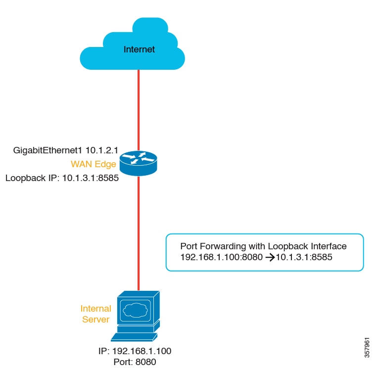
From Cisco IOS XE Catalyst SD-WAN Release 17.11.1a and later releases, you can configure loopback interfaces for port forwarding with NAT DIA. Loopback interfaces ensure that the IP address assigned to the interface is always reachable if the IP routing protocols continue to advertise the subnet that is assigned to the loopback interface. After the loopback interface and the port number are configured, the source IP address and the source port number are translated to the loopback IP address and port number respectively.

From Cisco IOS XE Catalyst SD-WAN Release 17.11.1a, you can configure loopback interfaces by either using device CLI templates or CLI add-on feature templates.

Figure 5. NAT DIA Port Forwarding by Using a Loopback interface
Port forwarding with loopback interface
Benefits of Port Forwarding with NAT DIA
  • Allows you to reach servers in a private network (LAN) from the public domain

  • Allows you to forward different ports to different internal IP addresses, allowing multiple servers to be accessible from the same public IP address

Restrictions for Port Forwarding with NAT DIA

Minimum supported releases: Cisco IOS XE Catalyst SD-WAN Release 17.9.1a, Cisco vManage Release 20.9.1

  • TCP load balancing isn’t supported for port forwarding with NAT DIA.

  • Traffic can reach public IP addresses and ports from the public network only.

  • If you have configured static NAT, you can’t use the same static NAT IP addresses when configuring port forwarding.

  • You can’t use Cisco SD-WAN Manager-reserved ports when configuring port forwarding with NAT DIA.

  • No support for loopback interfaces in Cisco IOS XE Catalyst SD-WAN Release 17.10.1a or earlier releases.

    In Cisco IOS XE Catalyst SD-WAN Release 17.11.1a, you can configure loopback interfaces for port forwarding with NAT DIA. For more information about configuring the loopback interface, see Configure Port Forwarding with NAT DIA Using a CLI Template

  • No support for dialer virtual interfaces.

  • UDP ports 8000-48199 are reserved for VoIP traffic. If VoIP is enabled on a Cisco IOS XE Catalyst SD-WAN device, NAT DIA can’t use the same UDP ports that are reserved for VoIP traffic.

  • NAT DIA port forwarding for a TLOC egress interface doesn’t support fragmented packets sourced from outside the network.

  • Define up to 128 port-forwarding rules to allow requests from an external network to reach devices on the internal network.

  • An IP address plus a port number to an IP address plus a port number translation is supported using Cisco SD-WAN Manager feature templates and CLI templates.

  • Interface port forwarding is supported using a CLI template only.

    When you use an interface rather than an IP address in your port-forwarding rule, this is known as interface port forwarding.

Configure Port Forwarding with NAT DIA

Minimum supported releases: Cisco IOS XE Catalyst SD-WAN Release 17.9.1a, Cisco vManage Release 20.9.1

Create port-forwarding rules to allow access to a private network from the public domain.

Before You Begin
  1. Configure and apply a data policy.

  2. Configure a Cisco VPN Interface Ethernet template or edit an existing Cisco VPN Interface Ethernet template.

  3. Configure interface overload mode. Interface overload mode is enabled by default.

  4. Configure a NAT pool.

Configure Port Forwarding with NAT DIA
  1. From the Cisco SD-WAN Manager menu, choose Configuration > Templates.

  2. Click Feature Templates.


    Note


    In Cisco vManage Release 20.7.x and earlier releases, Feature Templates is titled Feature.


  3. To edit a Cisco VPN Interface Ethernet template, click … adjacent to the template name and choose Edit.

  4. Click NAT.

  5. Under NAT Pool, click New NAT Pool.

  6. Enter the required NAT pool parameters.

  7. Click Add.

  8. To create a port-forwarding rule, click Port Forward > New Port Forwarding Rule and configure the parameters as described in the table.

    Table 5. Port-Forwarding Parameters for NAT DIA

    Parameter Name

    Description

    Protocol

    Choose the TCP or UDP protocol to which to apply the port-forwarding rule. To match the same ports for both TCP and UDP traffic, configure two rules.

    Source IP Address

    Enter the source IP address to be translated.

    Source Port

    Enter a port number to define the source port to be translated.

    Range is 0 to 65535.

    Translated Source IP Address

    Specify the NAT IP address that will be advertised into OMP. Port forwarding is applied to traffic that is destined to this IP address from the overlay with the translated port match.

    Translate Port

    Enter the port number to apply port forwarding to.

    Range is 0 to 65535.

    Beginning with Cisco IOS XE Catalyst SD-WAN Release 17.5.1a, static translated source IP addresses must be within the configured dynamic NAT pool IP address range.

    Static NAT Direction

    Select the direction in which to perform network address translation.

    Source VPN ID

    Specify the service-side VPN from which the traffic is being sent.

  9. Click Update.


Note


If you are using Cisco Catalyst SD-WAN Manager Release 20.12.x and Cisco IOS XE Catalyst SD-WAN Release 17.9.x, SD-WAN Manager cannot push NAT port forwarding configurations due to a YANG model incompatibility. To resolve this, either switch the router to CLI mode to configure port forwarding manually or upgrade the router to Cisco IOS XE Catalyst SD-WAN Release 17.12.x.


Configure Port Forwarding with NAT DIA Using a CLI Template

Minimum supported releases: Cisco IOS XE Catalyst SD-WAN Release 17.9.1a, Cisco vManage Release 20.9.1

For more information on using CLI templates, see CLI Templates and CLI Add-On Feature Templates.

  1. Configure ip nat outside on the WAN interface.

    interface interface-type-number
     ip address dhcp
     ip nat outside
     negotiation auto
     no mop enabled
     no mop sysid
    end
  2. Configure interface overload mode on the WAN interface.

    ip nat inside source list nat-acl interface interface-type-number overload
  3. Configure NAT DIA port forwarding using an egress interface.

    ip nat inside source static tcp ip-address port ip-address port vrf number egress-interface interface-type-number
    ip nat inside source static tcp ip-address port interface interface-type-number port vrf number

    The ip nat inside source static tcp ip-address port interface interface-type-number port vrf number command is an example of interface port forwarding, because you use an interface rather than an IP address in the port-forwarding rule.


    Note


    You can configure interface port forwarding using a Cisco SD-WAN Manager feature template.


Here is a complete configuration example for configuring port forwarding with NAT DIA.

interface GigabitEthernet1
 ip address 10.1.2.1 255.255.255.0
 ip nat outside
 negotiation auto
 no mop enabled
 no mop sysid
end

ip nat inside source list nat-dia-vpn-hop-access-list interface GigabitEthernet1 overload
ip nat inside source static tcp 192.168.1.100 443 interface GigabitEthernet1 8443 vrf 1
ip nat inside source static tcp 192.168.1.100 80 10.1.2.10 80 vrf 1 egress-interface GigabitEthernet1 
ip nat inside source static tcp 192.168.1.100 22 10.1.2.20 2020 vrf 1 egress-interface GigabitEthernet1
Port forwarding with NAT DIA using a loopback interface

From Cisco IOS XE Catalyst SD-WAN Release 17.11.1a, you can configure loopback interfaces for port forwarding with NAT DIA. While configuring a loopback interface, provide the egress interface, which is the internet-facing interface.

Here is a configuration example for configuring port forwarding with NAT DIA by using a loopback interface.

Configure ip nat outside on the WAN interface:

interface GigabitEthernet1
 ip address 10.1.2.1 255.255.255.0
 ip nat outside
 negotiation auto
 no mop enabled
 no mop sysid
exit

Define the loopback interface:

interface Loopback3
 ip address 10.1.3.1 255.255.255.255
exit

Configure the loopback interface:

ip nat inside source static tcp 192.168.1.100 8080 interface Loopback3 8585 vrf 1 egress-interface GigabitEthernet1
ip nat inside source static tcp 192.168.1.100 80 interface Loopback3 5050 egress-interface GigabitEthernet1 

In the preceding configuration example, the incoming TCP packet with the source IP address of 192.168.1.100 is translated to the IP address assigned to Loopback3, which is 10.1.3.1. The source port 8080 is translated to 8585.

If you specify a VRF number in the range of 1–512, port forwarding occurs within the service VPN. When you don’t specify a value for the VRF number, port forwarding is configured on the transport VPN, which is VPN 0, by default.

The loopback interface remains active till you run the shutdown command in the interface configuration mode.

Verify Configuration of Port Forwarding with NAT DIA

Verify Translations for Port Forwarding with NAT DIA

Minimum supported releases: Cisco IOS XE Catalyst SD-WAN Release 17.9.1a, Cisco vManage Release 20.9.1

The following is a sample output from the show ip nat translations command:

Device# show ip nat translations
Pro  Inside global         Inside local          Outside local         Outside global
tcp  10.0.1.7:2022         10.0.100.14:22        ---                   ---
tcp  10.0.1.7:2022         10.0.100.14:22        10.0.1.16:46275       10.0.1.16:46275
Total number of translations: 2

In the output above, inside global IP 10.0.1.7 with port 2022 is translated to an inside local IP of 10.0.100.14 with port 22.

Verify Translations for Port forwarding using a loopback interface

Minimum supported releases: Cisco IOS XE Catalyst SD-WAN Release 17.11.1a, Cisco vManage Release 20.11.1

The following is a sample output from the show ip nat translations command:

Device# show ip nat translations
Pro  Inside global         Inside local          Outside local         Outside global
tcp  10.1.3.1:5050         192.168.1.100:80        ---                   ---
tcp  10.1.3.1:8585         192.168.1.100:8080      ---                   ---
Total number of translations: 2

In the output above, the source IP 192.168.1.100 with port 8080 is translated to the loopback IP 10.1.3.1 with port 8585.

NAT High-Speed Logging

The following sections provide information on configuring Network Address Translator (NAT) High-Speed Logging (HSL) with NAT Direct Internet Access (DIA).

Information About NAT HSL

Minimum supported releases:
Cisco IOS XE Catalyst SD-WAN Release 17.9.1a
Cisco IOS XE Release 17.6.4 and later 17.6.x releases

NAT HSL lets you enable or disable NAT high-speed logging for virtual routing and forwarding (VRF) instances. When HSL is configured, NAT provides a log of the packets flowing through the routing devices (similar to the Version 9 NetFlow-like records) to an external collector. NAT translations exported to an external collector can include service-side VRF to global DIA and intra-service VRF (service-side VRF NAT) translations. When sessions are created and deleted, records are generated for each binding (binding is the address binding the local address and the global address to which the local address is translated).

You can turn on the collector for viewing the HSL information for NAT. You can turn on HSL only when required, and HSL log records are created and sent to the collector accordingly. This saves CPU cycles and bandwidth by not creating and sending HSL logging records when not needed.

Benefits of NAT HSL
  • Supports the sending of flow monitor records for NAT operations to an external collector.

  • Enables creation and sending of HSL records only when required, which saves CPU cycles and bandwidth.

  • Sends an HSL message automatically when a NAT pool runs out of addresses (also referred to as pool exhaustion).

Restrictions for NAT HSL

  • Service-side NAT VRF does not support IPv6 addresses.

  • Export of an IPv6 target in a service-side VRF is not supported.

  • Export of translations using IPv6 in a VRF is not supported.

Prerequisites for NAT HSL

  • Ensure that the NAT translations are available on the router.

  • Confirm that the log messages are being generated.

Best Practices for NAT HSL

  • Verify that the configured IP address and port address for logging are as per the configurations in the collector.

  • Use the show interface statistics command to verify the output packet counters and confirm the flow of packets from the router interface connecting to the collector.

Configure NAT HSL Using a CLI Template


Note


By default, CLI templates execute commands in global configuration mode.


The following is a sample CLI configuration to enable the high-speed logging of translations by NAT using a flow exporter:

ip nat log translations flow-export v9 udp destination IPv4address-port source interface-name interface-number 

The following is a configuration example to enable translation logging for a specific destination and source interface:

ip nat log translations flow-export v9 udp destination 10.10.0.1 1020 source gigabithethernet 0/0/1

Verify NAT HSL Configuration

The following is a sample output from the show ip nat translations command. You can view the translations log in the export target collector.

Device# show ip nat translations
Pro  Inside global      Inside local          Outside local         Outside global
------------------------------------------------------------------------------------------
tcp  10.0.0.16:5092     10.0.0.16:56991       209.165.202.129:80    209.165.202.129:80
tcp  10.0.0.16:5078     10.0.0.16:55951       172.16.128.7:80       172.16.128.7:80
tcp  10.0.0.16:5070     10.0.0.16:57141       172.16.128.7:80       172.16.128.7:80
tcp  10.0.0.16:5089     10.0.0.16:55823       209.165.202.129:80    209.165.202.129:80
tcp  10.0.0.16:5103     10.0.0.16:58717       172.16.128.7:80       172.16.128.7:80
tcp  10.0.0.16:5064     10.0.0.16:55413       209.165.202.129:80    209.165.202.129:80
tcp  10.0.0.16:5091     10.0.0.16:59331       209.165.202.129:80    209.165.202.129:80
tcp  10.0.0.16:5100     10.0.0.16:59795       209.165.202.129:80    209.165.202.129:80
tcp  10.0.0.16:5097     10.0.0.16:57695       209.165.202.129:80    209.165.202.129:80
tcp  10.0.0.16:5096     10.0.0.16:55665       209.165.202.129:80    209.165.202.129:80
tcp  10.0.0.16:5066     10.0.0.16:58671       172.16.128.7:80       172.16.128.7:80

The following is a sample output from the show platform hardware qfp active feature nat datapath hsl command that is used to verify the configurations:

Device# show platform hardware qfp active feature nat datapath hsl
HSL cfg dip 10.10.0.1 dport 1020 sip 10.21.0.16 sport 53738 vrf 0
nat hsl handle 0x3d007d template id 261 pool_exh template id 263
LOG_TRANS_ADD 132148
LOG_TRANS_DEL 132120
LOG_POOL_EXH 0 

The following is a sample output from the show vrf detail command:

Device# show vrf detail
VRF 1 (VRF Id = 1); default RD <not set>; default VPNID <not set>
  New CLI format, supports multiple address-families
  Flags: 0x1808
  Interfaces:
    Gi0/0/1      Gi0/0/2.102      Lo0    Vl103
Address family ipv4 unicast (Table ID = 0x1):
  Flags: 0x0
  No Export VPN route-target communities
  No Import VPN route-target communities
  No import route-map
  No global export route-map
  No export route-map
  VRF label distribution protocol: not configured
  VRF label allocation mode: per-prefix
Address family ipv6 unicast (Table ID = 0x1E000001):
  Flags: 0x0
  No Export VPN route-target communities
  No Import VPN route-target communities
  No import route-map
  No global export route-map
  No export route-map
  VRF label distribution protocol: not configured
  VRF label allocation mode: per-prefix
Address family ipv4 multicast not active
Address family ipv6 multicast not active

Source Port Preservation for Known Cisco Catalyst SD-WAN Ports

The following sections provide information for well-known Cisco Catalyst SD-WAN ports.

Information About Source Port Preservation for the Well-Known Cisco Catalyst SD-WAN Ports

Cisco Catalyst SD-WAN deployment uses UDP port number ranging 12346 to 12445 and TCP ports ranging 23456 to 24356 for control connections on Cisco IOS XE Catalyst SD-WAN devices. When an external Cisco IOS XE Catalyst SD-WAN device is behind the firewall during NAT, the control traffic port can translate to a different port. This is normally not an issue but when BFD sessions go down, NAT translates the new BFD control packet to a different port. The firewall doesn't accept the newly translated port and drops BFD packets as it has saved translated port of the older BFD session.

With this feature, you can configure Cisco IOS XE Catalyst SD-WAN devices to preserve the source ports for the known Cisco Catalyst SD-WAN ports during NAT. There is a set of reserved ports for the control traffic and within this range the ports are preserved during NAT. On enabling this feature, Cisco IOS XE Catalyst SD-WAN device preserves the source port from the known SD-WAN port range. Thus, firewall can handle Cisco Catalyst SD-WAN devices behind NAT.


Note


Ensure that no service side traffic uses these port ranges, else it results in control connections failure.


Enabling the feature allows source port preservation for control traffic using Cisco Catalyst SD-WAN known ports for the following NAT mapping conditions:

  • Interface overload

  • Loopback overload

Figure 6. Topology of Source Port Preservation in Cisco Catalyst SD-WAN Deployment
The topology depicts a dual route site SD-WAN deployment to reserve the source ports for the well-known SD-WAN ports.

The topology depicts a dual router site. cE1 has tloc-extension configured to use cE2 for INET connectivity to reach controllers. cE1 is using the known Cisco Catalyst SD-WAN port 12346, when the packet reaches cE2. The NAT functionality on cE2 preserves this source port number 12346 and doesn't change it before sending the packets out.

Features of Source Port Preservation

  • The traffic with the specified port within the reserved port range is translated to the same port after configuring ip nat settings preserve-sdwan-ports command.

  • As the locally generated traffic does not go through NAT, they always get port preservation in the reserved port range. If a local and an external device are using the same port in the reserved port range, the local traffic gets the preference.

  • Reserved ports for UDP are in the range 12346—12426, and for TCP reserved port range is 23456—24356.

  • TLS (TCP) control connections can take port value > 1024. As source port preservation is only supported for the reserved port range 23456—24356 for TCP, any other port value may not be preserved after translation.

Prerequisites for Source Port Preservation

If there are existing NAT mapping configurations, ensure that you reboot the device after configuring the ip nat settings preserve-sdwan-ports command to achieve the expected behavior. If not, add NAT mapping configurations after configuring the ip nat settings preserve-sdwan-ports command.

Restrictions for Source Port Preservation

  • Service-side traffic cannot use the reserved port range.

  • If the Cisco Catalyst SD-WAN well-known port is already allocated for a flow and another flow requests translation for the same port, then the packets for the new flows are dropped.

  • If there are existing NAT mapping configurations, reboot the device after executing the ip nat settings preserve-sdwan-ports command to achieve the expected behavior. If not, add the NAT mapping configurations after executing the ip nat settings preserve-sdwan-ports command.

Configure Source Port Preservation for DIA Interface Overload Using a CLI Template


Note


By default, CLI templates execute commands in global config mode.


This section provides example CLI configurations to configure source ports preservation for the known Cisco Catalyst SD-WAN ports during NAT.

  1. Enable source port preservation during NAT:

    ip nat settings preserve-sdwan-ports
  2. Enable NAT of the inside source address for DIA interface overload:

    ip nat inside source list nat-dia-vpn-hop-access-list interface GigabitEthernet1 overload
    
  3. Configure an interface type and enter the interface configuration mode:

    interface GigabitEthernet1
  4. Enable the interface:

    no shutdown
  5. Configure the IP address:

    ip address 10.1.16.16 255.255.255.0
  6. Connect the interface to the outside network:

    ip nat outside 
Here's the complete configuration examples for port preservation during DIA interface overload:

ip nat settings preserve-sdwan-ports
ip nat inside source list nat-dia-vpn-hop-access-list interface GigabitEthernet1 overload
!
interface GigabitEthernet1
 no shutdown
 ip address 10.1.16.16 255.255.255.0
 ip nat outside 

Configure Source Port Preservation for DIA Pool Overload Using a CLI Template


Note


By default, CLI templates execute commands in global config mode.


This section provides example CLI configurations to configure source ports preservation for the known Cisco Catalyst SD-WAN ports during NAT.

  1. Enable source port preservation during NAT:

    ip nat settings preserve-sdwan-ports
  2. Define a pool of IP addresses for NAT:

    
    ip nat pool natpool-GigabitEthernet1-0 10.1.16.201 10.1.16.250 prefix-length 24
  3. Enable NAT of the inside source address for DIA pool overload:

    
    ip nat inside source list global-list pool natpool-GigabitEthernet1-0 overload egress-interface GigabitEthernet1
  4. Configure an interface type and enter the interface configuration mode.

    interface GigabitEthernet1
  5. Enable the interface:

    no shutdown
  6. Configure the IP address.

    ip address 10.1.16.16 255.255.255.0
  7. Connect the interface to the outside network.

    ip nat outside 
Here's the complete configuration examples for port preservation during DIA pool overload:

ip nat settings preserve-sdwan-ports
ip nat pool natpool-GigabitEthernet1-0 10.1.16.201 10.1.16.250 prefix-length 24
ip nat inside source list global-list pool natpool-GigabitEthernet1-0 overload egress-interface GigabitEthernet1
!
interface GigabitEthernet1
 no shutdown
 ip address 10.1.16.16 255.255.255.0
 ip nat outside 

Configure Source Port Preservation for DIA Loopback Overload Using a CLI Template


Note


By default, CLI templates execute commands in global config mode.


This section provides example CLI configurations to configure source ports preservation for the known Cisco Catalyst SD-WAN ports during NAT.

  1. Enable source port preservation during NAT:

    ip nat settings preserve-sdwan-ports
  2. Enable NAT of the inside source address for DIA loopback overload:

    
    ip nat inside source list global-list interface Loopback16 overload egress-interface GigabitEthernet1
    
  3. Configure the loopback interface:

    interface Loopback16
  4. Configure the IP address on the loopback interface:

    ip address 10.20.16.16 255.255.255.0
  5. Configure an interface type and enter the interface configuration mode:

    interface GigabitEthernet1
  6. Configure the IP address:

    ip address 10.1.16.16 255.255.255.0
  7. Connect the interface to the outside network:

    ip nat outside 
Here's the complete configuration examples for port preservation during DIA loopback overload:

ip nat settings preserve-sdwan-ports
ip nat inside source list global-list interface Loopback16 overload egress-interface GigabitEthernet1
!
interface Loopback16
 ip address 10.20.16.16 255.255.255.0
!
interface GigabitEthernet1
 ip address 10.1.16.16 255.255.255.0
 ip nat outside 

Verify Source Port Preservation

The following is a sample output from the show ip nat translations command displaying the translations with well-known Cisco Catalyst SD-WAN source ports. Observe the inside local and inside global columns for the translations and verify the source ports being preserved:

Device# show ip nat translations
Pro  Inside global          Inside local          Outside local         Outside global
udp  10.1.16.201:12406      10.1.19.15:12406      10.0.5.21:12377       10.0.5.21:12377
udp  10.1.16.201:12406      10.1.19.15:12406      10.0.5.19:12355       10.0.5.19:12355
udp  10.1.16.201:12406      10.1.19.15:12406      10.0.5.11:12367       10.0.5.11:12367
udp  10.1.16.201:12406      10.1.19.15:12406      10.0.12.26:12346      10.0.12.26:12346
udp  10.1.16.201:12406      10.1.19.15:12406      10.1.14.14:12366      10.1.14.14:12366
udp  10.1.16.201:12406      10.1.19.15:12406      10.0.12.20:12356      10.0.12.20:12356
Total number of translations: 6

The following is a sample output from the show sdwan bfd sessions table command displaying the traffic with ports in control plane:

Device# show sdwan bfd sessions table
                               SRC    DST                   SITE                                     DETECT      TX                                 
SRC IP      DST IP      PROTO  PORT   PORT   SYSTEM IP      ID    LOCAL COLOR   COLOR         STATE  MULTIPLIER  INTERVAL  UPTIME      TRANSITIONS  
----------------------------------------------------------------------------------------------------------------------------------------------------
10.1.15.15  10.0.5.11   ipsec  12366  12367  172.16.255.11  100   lte           lte           up     7           1000      0:01:37:43  3            
10.1.19.15  10.0.5.11   ipsec  12406  12367  172.16.255.11  100   biz-internet  lte           up     7           1000      0:00:00:51  0            
10.1.15.15  10.1.14.14  ipsec  12366  12366  172.16.255.14  400   lte           lte           up     7           1000      0:01:37:43  3            
10.1.19.15  10.1.14.14  ipsec  12406  12366  172.16.255.14  400   biz-internet  lte           up     7           1000      0:00:00:51  0            
10.1.15.15  10.1.16.16  ipsec  12366  12386  172.16.255.16  600   lte           biz-internet  up     7           1000      0:00:31:41  0            
10.1.19.15  10.1.16.16  ipsec  12406  12386  172.16.255.16  600   biz-internet  biz-internet  down   7           1000      NA          0            
10.1.15.15  10.0.5.21   ipsec  12366  12377  172.16.255.21  100   lte           lte           up     7           1000      0:01:37:43  3            
10.1.19.15  10.0.5.21   ipsec  12406  12377  172.16.255.21  100   biz-internet  lte           up     7           1000      0:00:00:51  0            

Destination NAT

Minimum supported releases: Cisco IOS XE Catalyst SD-WAN Release 17.11.1a and Cisco vManage Release 20.11.1

The following sections provide information on configuring Destination NAT with NAT Direct Internet Access (DIA).

Information about Destination NAT

Minimum supported releases: Cisco IOS XE Catalyst SD-WAN Release 17.11.1a and Cisco vManage Release 20.11.1

When you send a packet from the service side to the internet, NAT Direct Internet Access (DIA) translates the destination IP address, which can also be a private IP address, to a public IP address. This is known as destination NAT.

Any WAN edge device situated between two endpoints can be used to perform destination NAT. Destination NAT is used to redirect incoming packets with the destination of a private IP address to a public IP address. It is generally used to redirect packets destined for a specific IP address on one host to a different address on a different host.

Restrictions for Destination NAT

Minimum supported releases: Cisco IOS XE Catalyst SD-WAN Release 17.11.1a and Cisco vManage Release 20.11.1

  • Only NAT DIA is supported with destination NAT.

  • Only traffic originating from inside to outside direction is supported.

  • Only data-policy-based DIA is supported.

  • Does not support route-based DIA configurations.

  • Does not support port forwarding with NAT DIA.

  • Same NAT rules for packets are not applicable on different VRFs.

  • NAT is not supported over SIG tunnel interface.

Use Case for Destination NAT

Minimum supported releases: Cisco IOS XE Catalyst SD-WAN Release 17.11.1a and Cisco vManage Release 20.11.1

A customer device using a Cisco VPN client initiates a DNS query to the device operating the firewall service, which is assigned with a private IP address. This private IP address is the overlay IP address. In case NAT DIA is not configured, the data policy uses VPN 0 fallback to the overlay to send the traffic to the firewall with the private IP address. The overlay IP address, which is a private IP address, is translated to a public IP address.

The prefered path for the traffic route is through the path with NAT DIA configured, where both the source and the destination IP addresses are translated.

Figure 7. Use Case for Destination NAT

1

Path without NAT configured

2

Path with NAT configured

Configure Destination NAT Using a CLI Template

Minimum supported releases: Cisco IOS XE Catalyst SD-WAN Release 17.11.1a and Cisco vManage Release 20.11.1


Note


By default, CLI templates execute commands in global config mode.


To enable NAT of the outside source address:

ip nat outside source static local-ip-address global-ip-address vrf vrf-name

Here's a complete configuration example for destination NAT:

ip nat outside source static 192.0.200.3 10.2.57.51 vrf 1

Verify Destination NAT

Minimum supported releases: Cisco IOS XE Catalyst SD-WAN Release 17.11.1a and Cisco vManage Release 20.11.1

The following is a sample output from the show sdwan policy from-vsmart command.


Device# show sdwan policy from-vsmart 

from-vsmart data-policy _1_vm5-vpn1-dia-policy
 direction all
 vpn-list 1
  sequence 1
   match
    source-ip      10.20.24.0/24
    destination-ip 10.2.57.51/24
   action accept
    nat use-vpn 0
    nat fallback
from-vsmart lists vpn-list 1
 vpn 1

In this example, you can check for the destination IP address and if the NAT fallback feature is configured.

The following is a sample output from the show ip nat translations command.


Device# show ip nat translations

Pro   Inside global    Inside local    Outside local     Outside global
---   ---              ---             10.2.57.51        192.0.2.1
tcp   203.0.113.1:5062 10.0.0.1:30427  10.2.57.51:1024   192.0.2.1:1024         

In this example, the outside local IP address shows the private IP address that is translated to a public IP address in outside global .

Troubleshoot Destination NAT

Minimum supported releases: Cisco IOS XE Catalyst SD-WAN Release 17.11.1a and Cisco vManage Release 20.11.1

To check the original and the translated IP address, use the show platform hardware qfp active feature nat datapath bind command.


Device# show platform hardware qfp active feature nat datapath bind 

Bind longest chain 1 avg non-zero bucket len 1 non-zero bkts 2
bind 0xed7739c0 oaddr 8.8.8.8 taddr 4.1.1.5 oport 0 tport 0 vrfid 1 tableid 1 proto 0 domain 1 create time 78840 refcnt 1 mask 0x0 cgn flags 0 timeout 0 ifhandle 0 wlan_info 0x0 flags 0x2100 mapping 0x0 cp_mapping_id 1 limit_type 0  last_use_ts 82071 mibp 0x0 bind_pool_id: 0 rg 0 nak_retry 0 parent 0x0 egress_ifh 0 in2out_pkts 0 out2in pkts 0

To check if the traffic is going on the DIA interface, check the packet count using the show sdwan policy data-policy-filter command.


Device# show sdwan policy data-policy-filter 
                                                   POLICER  OOS      OOS    
NAME  NAME   COUNTER NAME          PACKETS  BYTES  NAME     PACKETS  BYTES  
----------------------------------------------------------------------------
u5    vpn-1  DNAT-DIA-COUNTER      5        570                             
             default_action_count  158      14340 

To check the traffic flow on the fallback interface when the DIA interface is down, use the show plat hard qfp active feature sdwan datapath statistics | inc fallback


Device# show plat hard qfp active feature sdwan datapath statistics | inc fallback

data-policy-in-sig-fallback-flow-set-fail 0
data-policy-in-nat-fallback 0
data-policy-out-nat-fallback 0