Cisco N560-RSP4 and Cisco N560-RSP4-E Route Processor Hardware Installation Guide
Bias-Free Language
The documentation set for this product strives to use bias-free language. For the purposes of this documentation set, bias-free is defined as language that does not imply discrimination based on age, disability, gender, racial identity, ethnic identity, sexual orientation, socioeconomic status, and intersectionality. Exceptions may be present in the documentation due to language that is hardcoded in the user interfaces of the product software, language used based on RFP documentation, or language that is used by a referenced third-party product. Learn more about how Cisco is using Inclusive Language.
N560-RSP4 route processor is a medium-scale route processor with 800 Gbps throughput, maximum 700MPPS packet processing rate,
and wide form factor.
N560-RSP4-E route processor is a large-scale route processor with 800 Gbps throughput, maximum 700MPPS packet processing rate,
and wide form factor.
For more information on N560-RSP4 and N560-RSP4-E route processors, see Product specifications.
The N560-RSP4 and N560-RSP4-E route processors (RSPs) increase the system capacity, interface density and scale of the routers
they are installed in. These RSPs operate on the 64-bit IOS-XR (eXR) operating system and are designed to support 1:1 redundancy
for the data plane. Both RSPs receive and forward traffic; however, only the active data plane forwards traffic to the external
network.
The N560-RSP4 and N560-RSP4-E are supported on the Cisco ASR 907 Routers (which effectively turns the Cisco ASR-907 Router
into an NCS560-7 Router, running the Cisco IOS-XR software) and can be installed in any available route processor slot in
these chassis.
Note
Do not use the N560-RSP4 and N560-RSP4-E route processors together in the same router.
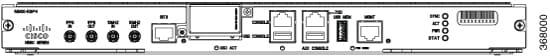
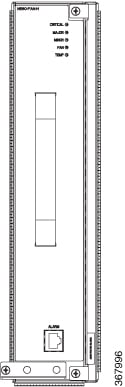
Figure 1. N560-RSP4 Front Panel
Figure 2. N560-RSP4-E Front Panel
RSP Redundancy
When two RSPs are installed in a router, one RSP is the active RSP and the other is a backup, or standby, RSP. If the active
RSP fails or is removed from the system, the standby RSP detects the failure and initiates a switchover. During a switchover,
the standby RSP assumes control of the router, connects with the network interfaces, and activates the local network management
interface and system console.
Note
If your system includes redundant RSPs, both RSPs should be of the same type and have the same memory size. We strongly recommend
that you avoid configuring your router using mixed route processor cards.
External Interfaces
Network Interfaces
The N560-RSP4 and N560-RSP4-E modules support the following network interfaces through the pluggable IMs:
GE SFP ports – supporting 1000/1GE modes with A900-IMA-8CS1Z-M
GE C-SFP ports – supporting 1000/1GE BASE-BX modes with A900-IMA-8CS1Z-M
10GE SFP+ ports – supporting 10GE mode with A900-IMA-8CS1Z-M, A900-IMA-8Z, and A900-IMA-8Z-L IMs
100GE QSFP-28/QSFP-DD 100G ZF1/QSFP+ Ethernet ports using 2 x 100GE IM – supporting both 100GE and 40GE with N560-IMA-2C.
Effective Cisco IOS XR Release 7.3.2, only 100GE is supported on the N560-IMA-2C-DD. Effective Cisco IOS XR Release 7.8.1 Quad Small Form-Factor Pluggable Double Density (QSFP-DD 100G ZF1) is supported on the interface module. Only 100GE is supported
in a single fixed wavelength mode.
Network Timing Interfaces
The following network timing interfaces are located on the RSP:
BITS simultaneous input and output (T1/E1)—RJ48 jack
1PPS input—mini-coaxial connector
1PPS output—mini-coaxial connector
2.048/10MHz input—mini-coacoaxialx connector
2.048/10MHz output—mini-coax connector
ToD input or output—shielded RJ45 jack
GNSS RF input port—To support high availability, an RSP GPS support with single antenna, external passive splitter is required
to split output while maintaining the minimum RF power input required by GNSS receiver.
The network interfaces are sources and destinations of frequency (for example, SyncE, T1/E1, SONET/SDH) and phase/ToD (for
example, IEEE 1588-2008 PTP).
Management Interfaces
Copper 10/100/1000Base-T LAN management port—RJ45 jack
Console/Aux RS232 serial ports—RJ45 jacks
Console—USB 2.0 type A receptacle
Mass Storage—USB 2.0 or 3.0 type A receptacle
Indicators
Status LEDs are present on the RSP. For more information on LED, see LED Details.
Licensing
The Cisco NCS 560 router with RSP4/RSP4-E utilizes Cisco’s IOS-XR Software Flexible Consumption Licensing Model. For information
on the IOS-XR Flexible Consumption License, see:
For the NCS 560 with RSP4 RSP4-E, the Flexible Consumption Model comprises two software suites:
The Essentials software suite is required for active ports in the system and is a per-100-Gbps capacity license.
The Advanced software suite is required when one or more of the Advanced software suite features are used (for example, L2VPN,
L3VPN, and E-VPN Services), and is on a per-100-Gbps capacity license.
The Essentials software suite supports the following features on a per-100-Gbps capacity license:
Starting with Cisco IOS XR Release 7.5.1, 1G mode is supported on A900-IMA8Z-L IM. Use the following command to configure A900-IMA8Z-L interface module in 1G mode:
hw-module quad1slot0mode1g
The A900-IMA-8CS1Z-M interface module is supported on 0-15 slots of the chassis. Out of the nine physical ports, the first
eight are CSFP ports, thus a total of 17 ports are present in the interface module. Out of these 17 ports of the interface
module, ports 0-15 are 1G CSFP ports and port 16 is 10G SFP+ port. However, for slots 0, 1, 14, and 15, you can only use the
even ports of the interface module. This is because the odd ports are unusable due to bandwidth restrictions.
Starting with Cisco IOS XR Release 7.4.2, the A900-IMA-8CS1Z-IM interface module is supported on slots 0, 1, 14, and 15 in 8 x 1G and 1 x 10 mode by disabling the
odd 1G ports. You can achieve this by using the following command to disable the eight unused odd ports (1, 3, 5, 7, 9, 11,
and 15) within the slots:
hw-module slot <0-15 >im-mode1
Out of the nine even ports of the interface module, ports 0, 2, 4, 6, 8, 10, 12, and 14 can be used as 1G ports and port 16
can be used as 10G port. Disabling the odd ports of the interface module helps increase the router's port density by optimizing
hardware resource utilization.
Table 1. Supported Interface Modules and Part Numbers for N560-RSP4 and N560-RSP4-E
RSP Module
Interface Modules
Part Number
Slot
N560-RSP4 and N560-RSP4-E
8-port Gigabit Ethernet SFP Interface Module (8 x 1GE)
A900-IMA8S
Not Supported
8-port Gigabit Ethernet RJ45 (Copper) Interface Module (8 x 1GE)
A900-IMA8T
Not Supported
1-port 10 Gigabit Ethernet XFP Interface Module (1 x 10GE)
A900-IMA1X
Not Supported
SFP Combo IM—8-port Gigabit Ethernet (8 x 1GE) and 1-port 10 Gigabit Ethernet (1 x 10GE)
A900-IMA-8S1Z
Not Supported
Copper Combo IM—8-port Gigabit Ethernet (8 x 1GE) and 1-port 10 Gigabit Ethernet Interface Module (1 x 10GE)
A900-IMA-8T1Z
Not Supported
2-port 10 Gigabit Ethernet Interface Module (2 x 10GE)
A900-IMA2Z
Not Supported
2-port 100 Gigabit Ethernet Interface Module (2 x 100GE)
1 Starting with Cisco IOS XR Release 7.2.1, 40G optics are supported on both slots.
2 Slots 7 and 9 are supported on 200G mode with 4 x 100G, 2 x 100G and 2 x 40G, and 4 x 40G combinations.
3 Starting with Cisco IOS XR Release 7.4.1,
A900-IMA-8Z and A900-IMA-8Z-L IMs are supported on slots 2,3,12,
and 13 as well. In these slots, only 4 ports will be supported.
If an IM is inserted in these slots, then ports 0-3 are created
on A900-IMA-8Z and ports 4-7 are created in case of
A900-IMA-8Z-L.
4 Starting with Cisco IOS XR Release
7.5.1, 1G mode is supported on A900-IMA8Z-L. Slots 2, 3, 4, 5 can be
in 10G or 1G mode. 2,3,12, and 13 are partial port slots where 0 to
3 ports are disabled. For the port combination 4,5,6,and 7 both 10G
and 1G modes are supported.
For slots 7 and 9, all the ports
support 10G or 1G mode.
For slots 4,5,10, and 11, only 10G
mode is supported for port combination 0,1,2, and 3. Both 1G and
10G modes are supported for port combination 4,5,6, and
7.
5 100G mode is enabled by default. Slots 0 and 1 are supported on
100G and 200G mode. Slots 2 and 3 are supported only on 100G
mode.
Note
Maximum number of supported IMs depends on the configuration. Also, there may be restrictions to use some IM combinations.
Contact your sales support for more information.
Table 2. Slot and Port Support for A900-IMA8Z-L for 1G Mode
6 Starting with Cisco IOS XR Release 7.4.1, A900-IMA-8Z and A900-IMA-8Z-L IMs are supported on slots 2,3,12, and 13 as well.
In these slots, only 4 ports will be supported. If an IM is inserted in these slots, then ports 0-3 are created on A900-IMA-8Z
and ports 4-7 are created in case of A900-IMA-8Z-L.
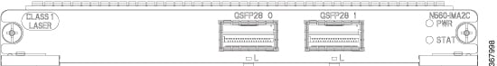
The 2 x 100 Gigabit Ethernet interface module (N560-IMA-2C) is a single-height and single-width card with 100 Gigabit Ethernet
port density support.
Figure 3. Cisco N560-IMA-2C Interface Module
Supported Modes
2 x 100 Gigabit Ethernet (fully subscribed)
Supported Optics on this IM
The N560-IMA-2C IM supports QSFP-28 optics, such as:
QSFP-100GE-SR4
QSFP-100GE-LR4
QSFP-100GE-ER4L
QSFP-40G-LR4
QSFP-40G-SR4
QSFP-40G-ER4
The 2 x 100 Gigabit Ethernet interface module (N560-IMA-2C-DD) is a single-height and single-width card with 100 Gigabit Ethernet
port density support. Effective Cisco IOS XR Release 7.8.1, Quad Small Form-Factor Pluggable Double Density (QSFP-DD 100G ZF1) transceiver module is supported.
Figure 4. Cisco N560-IMA-2C-DD Interface Module
The N560-IMA-2C-DD has an online removal switch (ORS) push button and an online removal indicator (ORI) LED on the front panel.
When pressed, the ORS triggers the command to stop all access to the optics. The ORI LED indicates that the system is ready
for optics removal. See the Interface Module LEDs section for more details.
Supported Modes
2 x 100 Gigabit Ethernet (fully subscribed)
Supported Optics on this IM
The N560-IMA-2C-DD IM supports QSFP-28 optics, such as:
QSFP-100G-LR4-S
QSFP-100G-SR4-S
QSFP-100G-CWDM4-S
QSFP-100G-SM-SR
QSFP-100G-ER4L-S
QSFP-100G-PSM4-S
The N560-IMA-2C-DD IM supports QSFP-DD 100G ZF1 optics, such as:
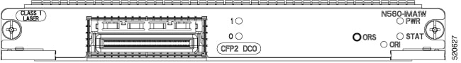
The 1-port 100GE/200GE CFP2 DCO Interface Module (N560-IMA-1W) is a single-width-single-height IM for the Cisco NCS 560-4
router and Cisco ASR 907 router with RSP4. This IM supports provides 2 virtual ports, under single physical port. One CFP2
Digital Coherent Optics (DCO) at 100G/200G (Ethernet/OTU4) capacity.
The N560-IMA-1W IM is designed to support industrial temperature operating range with industrial-temperature optics only.
However, if commercial-temperature optics are used, the IM operates at commercial temperature only.
The N560-IMA-1W has an online removal switch (ORS) push button and an online removal indicator (ORI) LED on the front panel.
When pressed, the ORS triggers the command to stop all access to the CFP2-DCO optics. The ORI LED indicates that the system
is ready for optics removal. See the Interface Module LEDs section for more details.
Note
ORS push button and ORI LED functionalities and ISSU are supported on the N560-IMA-1W only from Cisco IOS XR Release 7.2.2.
Supported Optics on this IM
CFP2-WDM-DET-1HL=
CFP2-WDM-D-1HL=
CFP2-WDM-DS100-HL=
CFP2-WDM-DETS-1HL=
CFP2-WDM-DS-1HL=
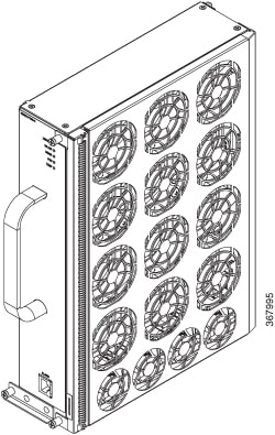
Fan Tray (FAN-H)
FAN-H enhances the thermal performance of the chassis. It supports industrial temperature ambient condition with industrial
temperature optics in the chassis.
Figure 6. Fan Tray Views
For information about the installation of the fan tray, see the Installing the Fan Tray section.
Fan Tray (A907-FAN-E)
The A907-FAN-E has:
Four dual rotor fans—for the PSU area cooling
12 fans (three columns for four fans)—60x60x38mm fans for the RSP and interface modules
This fan tray has redundant fans and provides side-to-side forced air cooling. A907-FAN-E is a field replaceable unit (FRU).
The following table describes the fan speed when used with the N560-RSP4 route processor.
Table 4. Ambient Temperature and Fan Speed
No.
Temperature (℃) at 1800m
System Fan Speed (% PWM)
PSU Fan Speed (% PWM)
Minimum
Maximum
1
-40
-11
30
30
2
-10
15
40
40
3
16
30
55
55
4
31
40
80
80
5
41
50
100
100
Note
The system considers the temperature of the fan inlet for the appropriate fan speed.
For information about the installation of the fan tray, see the Installing the Fan Tray section.
Online Insertion and Removal
The Cisco routers, interface modules, and FAN-H are designed to support online insertion and removal (OIR). However, time-to-OIR
for FAN-H fan tray is dependent on the temperature of the chassis. At room temperature of up to 30° C, fan tray OIR should
be done within two minutes.
Note
Before replacing the card, you must perform a graceful shutdown of the card to avoid disk corruption.
Table 5. Ambient Teperature and Fan Tray OIR
Ambient Temperature (in Celsius)
Fan Operation
Time
Remarks
30°
All fans are working
2 minutes
Fans working as expected
40°
All fans are working
1 minute 30 seconds
Fans working as expected
40°
Single fan failure
2 minutes
Single fan failure and all other fans running at maximum speed
Note
It is not recommended to perform fan tray OIR above the ambient temperature of 40° C.
The following table describes the parameters for the OIR of the various modules in the
router.
Note
Before replacing the card, you must perform a graceful shutdown of the card to avoid
disk corruption.
Table 6. Online Insertion and Removal - Parameters
7 It is not recommended to perform OIR of any module above
40°C ambient
8 Fan Tray OIR should be performed only when a fan's failed
condition is encountered and other fans are spinning at max
speed.
9 It is recommended to shut down the interface
modules before attempting to remove them from the
chassis.
Note
Consecutive IMs insertions, consecutive IMs reload or removal, and subsequent IM
re-oinsertion should be done while waiting at least 180s between the actions.
Power Supply Requirement
As the N560-RSP4 supports various interface modules, there are system configurations that require wattage higher than 1200W
to support the chassis power. In this case, (2+1) configuration is recommended for 1200W DC or 1200W AC power supply unit
(PSU), where the two PSUs are required for system operations and one PSU is redundant. In this case, all three PSUs are in
load sharing mode and the system continues to operate with one PSU failure. For more details on system power, see the CPC
tool or get in touch with your Cisco Sales contact.


 Feedback