G.8275.2 Profile

G.8275.2 profile

The G.8275.2 telecom profile is a Precision Time Protocol (PTP) profile that:

  • Provides phase and time-of-day synchronization in telecommunication networks

  • Operates with partial timing support from the network

  • Supports an optional hybrid full timing support mode

  • Uses PTP over IPv4 in unicast mode to achieve precise time synchronization

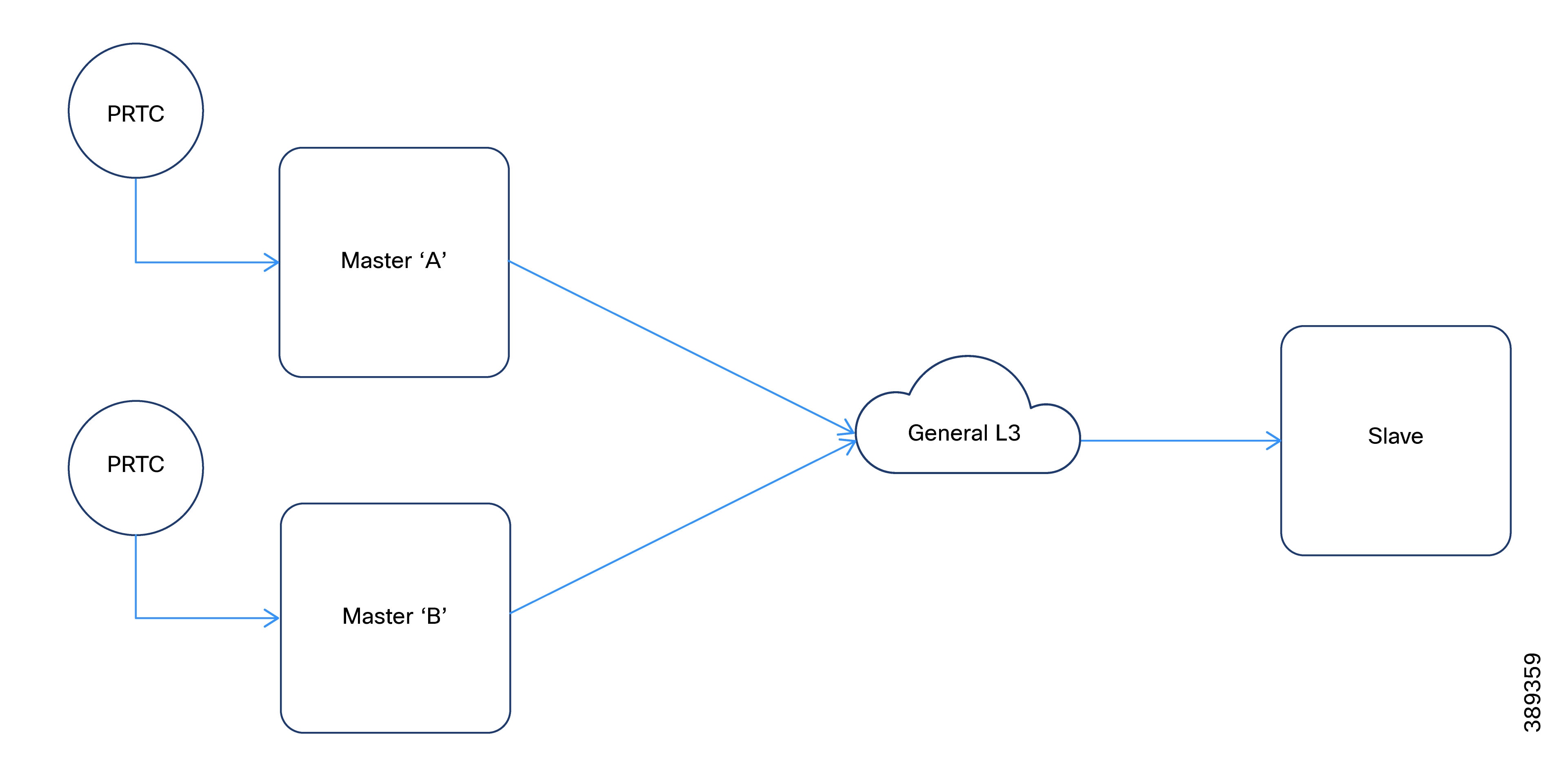
The G.8275.2 profile does not require every device in the network to participate in the PTP protocol. This profile is intended for use in carefully planned network environments where network behavior and performance, including static asymmetry, can be maintained within defined limits.

G.8275.2 clock types

The G.8275.2 profile supports partial timing, hybrid full timing, and three specific clock roles. It does not include assisted partial clock types.

G.8275.2 clock roles

The G.8275.2 profile supports these clock roles:

  • Telecom grandmaster (T-GM): A T-GM is a clock type that provides timing information to other devices in the network. The T-GM typically connects to a primary reference time source, such as a Global Navigation Satellite System (GNSS) receiver, and does not synchronize its local clock using other network elements.

  • Partial support telecom boundary clock (T-BC-P): A T-BC-P is a boundary clock that can act as a grandmaster, synchronize from another PTP clock, or provide time to a secondary clock.

  • Partial support telecom time slave clock (T-TSC-P): A T-TSC-P is a secondary clock that synchronizes its local clock to another PTP clock, such as a T-GM or T-BC-P. This clock does not provide synchronization to other devices.

PTP domain

Permitted PTP domain numbers for the G.8275.2 profile range from 44 to 63.

PTP messages and transport

The G.8275.2 profile requires PTP over IPv4 in unicast mode. The profile supports only one-step clock operation and unicast message negotiation.

The profile supports these modes:

  • Hybrid mode: Provides holdover with assistance from Synchronous Ethernet (SyncE) for T-TSC, T-BC, or T-GM devices. Enable hybrid mode on a T-GM that uses a virtual port GNSS as input.

  • Non-hybrid mode: Provides holdover without SyncE for T-TSC or T-BC devices. Enable non-hybrid mode on a T-GM that uses a virtual port (GNSS) as input.

The G.8275.2 profile uses these PTP messages.

  • sync

  • delay_req

  • announce

  • follow_up

  • delay_resp

  • signaling

Alternate best timetransmitter clock algorithm

This section explains the Alternate Best TimeTransmitter Clock Algorithm (BTCA) selection process and the role of its attributes in G.8275.2 PTP domains.

Alternate BTCA attributes

The G.8275.2 profile uses the BTCA, a modified version of the IEEE 1588 standard model. BTCA selects the primary time-transmitting clock, the Grandmaster, in a PTP domain. It enables each device to select its synchronization source and determine the operational state of its local ports.

The alternate BTCA evaluates these attributes in the order of selection priority:

clockClass: Indicates the traceability and accuracy of a PTP clock. A lower clockClass value indicates higher quality and traceability. For example, these values can mean the clock is traceable to a primary reference time source such as GNSS.

  • 6: T-GM traceable to the primary reference clock provided by the GNSS.

  • 7: T-GM previously traceable to the primary reference clock, currently in holdover within specification.

  • 135: T-BC previously traceable to the primary reference clock, currently in holdover within specification.

  • 160: T-GM previously traceable to the primary reference clock, currently in holdover out of specification and traceable to a Category 3 frequency source (OCXO in timing module).

  • 165: T-BC currently in holdover out of specification.

clockAccuracy: Specifies the accuracy of the clock time relative to a reference time. The value is expressed as a range, for example within 25 nanoseconds or within 100 nanoseconds (ns).

offsetScaledLogVariance: Provides a statistical measure of the clock’s stability. This attribute is a logarithmic representation of the variance of the clock offset, which indicates the stability of the time output.

priority2: Specifies a configurable numeric attribute used as a secondary tiebreaker if all other attribute values are equal. A lower value indicates higher priority.

Localpriority: Specifies a configurable numeric attribute used to determine clock priority. A lower value indicates higher priority. This attribute is the primary tiebreaker in the BTCA, is locally significant, and is defined in the router PTP configuration.

Virtual port support in G.8275.2 profile

A virtual PTP port enables T-GM and T-BC devices to receive frequency and phase inputs from electrical sources. T-GM and T-BC devices receive frequency inputs such as SyncE, GNSS 1PPS, and Time of Day (ToD). These devices support virtual ports in both hybrid and non-hybrid modes.


Note


SyncE is not supported in non-hybrid mode.


Virtual port operation

When configured to derive time and frequency from a GNSS source, T-GM and T-BC devices use the virtual port as the reference input.

Virtual ports participate in the alternate BTCA for T-BCs. In T-GM mode, specifically for primary only configurations, the device does not evaluate BTCA from G.8275.2 peers. Instead, the device uses local priority to select from multiple inputs, such as a virtual port or a G.8275.2 peer.

Virtual port selection

Virtual port selection uses these criteria:

  • T-GM: The virtual port is available for selection when GNSS is locked and the external SyncE reference source is in the QL-PRC state.

  • T-BC: The virtual port participates in the BTCA only when GNSS is locked and SyncE is in the QL-PRC state. If the system selects the virtual port as the primary clock, electrical inputs drive the PTP clock. The T-BC primary can be a virtual port or a WAN port, based on the alternate BTCA priority.

Virtual port attributes

Virtual ports locked to GNSS use these attributes:

  • clock class: 6

  • clock accuracy: 0x21, which is within 100 nanoseconds

  • offset scaled log variance: 0x4E5D.

Guidelines and limitations

The G.8275.2 PTP profile has these requirements and constraints.

  • Does not support Virtual Routing and Forwarding (VRF) or subinterfaces

  • Supports only the loopback interface and the Gigabit interfaces GigabitEthernet0/0/0 and GigabitEthernet0/0/1 as transport interfaces on the IR8340 platform

  • Excludes Pdelay_Req, Pdelay_Resp, Pdelay_Resp_Follow_Up and management messages.

  • Does not support virtual port configuration for ordinary clocks

  • Requires boundary clocks to implement configuration examples

  • Can cause temporary frequency and phase inaccuracies in non-hybrid mode or partial timing support when switching between sources

G.8275.2 deployment scenario

The figure illustrates a typical G.8275.2 network configuration. This network contains two primary clocks, one boundary clock and one secondary clock. Server A operates as the ordinary clock and Server B acts as the backup server clock and includes a virtual port.

Figure 1. Hybrid full timing support configuration topology

Configure G.8275.2 profile

The G.8275.2 Profile can be configured for partial timing support or for hybrid full timing support.

Configure G.8275.2 profile for partial timing support

Configuring G.8275.2 profile for partial timing support includes these configurations:

Configure T-GM

Perform this task to configure the T-GM for partial timing support and hybrid full timing support.

Procedure

Step 1

Configure global Sync-E

Step 2

Configure Sync-E on the border interface that connects to T-TSC-P.

Step 3

Configure loopback interface.

Step 4

Configure GNSS.

Step 5

Configure G.8275.2 PTP as a hybrid boundary clock.

  1. Use the ptp clock boundary domain domain-number hybrid profile g8275.2 command to enable the hybrid PTP boundary clock.

    Example:
    Device(config)#ptp clock boundary domain 44 hybrid profile g8275.2
  2. Use the priority2 priority-value command to set the Priority2 field (default for holdover).

    Example:
    Device(config-ptp-clk)#priority2 25
  3. Use the virtual-port port-id profile g8275.2 command to create a virtual port for GNSS input.

    Example:
    Device(config-ptp-clk)#virtual-port vp1 profile g8275.2
  4. Use the input 1pps R0 command to configure the virtual port for 1PPS timing input.

    Example:
    Device(config-ptp-virtual-port)#input 1pps R0
  5. Use the input tod R0 ubx command to configure the virtual port for ToD input.

    Example:
    Device(config-ptp-virtual-port)#input tod R0 ubx
  6. Use the priority2 priority-value command to define the priority for the virtual port.

    Example:
    Device(config-ptp-virtual-port)#priority2 25 
  7. Use the clock-port port-name master profile g8275.2 command to define a primary port for connection to a T-TSC-P or a T-BC-P.

    Example:
    Device(config-ptp-clk)#clock-port primary1 master profile g8275.2 

    Note


    The master keyword prevents any T-BC or T-TSC from becoming the primary clock. This T-GM can only function as the GMC.

  8. Use the transport ipv4 unicast interface loopback-interfacenegotiation command to configure the primary port to use the loopback interface for unicast transport.

    Example:
    Device(config-ptp-port)#transport ipv4 unicast interface Lo0 negotiation 
  9. (Optional) Use the clock-port port-name profile g8275.2 command to define a regular primary port without master keyword, for alternate BTCA rules.

    Example:
    Device(config-ptp-clk)#clock-port primary1 profile g8275.2 
  10. Use the transport ipv4 unicast interface loopback-interface negotiation command to configure the regular primary port to use the loopback interface.

    Example:
    Device(config-ptp-port)#transport ipv4 unicast interface Lo0 negotiation 
  11. (Optional) Use the clock source secondary-ip-address command to configure primary port to accept connections from specified secondary clocks.

    Example:
    Device(config-ptp-port)#clock source 2.2.2.4

    Replace secondary-ip-address with the actual IP address of the T-TSC-P loopback interface.


Configure global Sync-E

Perform this task to configure global Sync-E.

Procedure

Step 1

Use the configure terminal command to enter global configuration mode.

Example:
Device# configure terminal

Step 2

Use the esmc process command to enable the Ethernet Synchronization Messaging Channel (ESMC) process.

Example:
Device(config)#esmc process

Note


This step is not applicable for configuring backup source.

Step 3

Use the network-clock revertive command to enable revertive mode.

Example:
Device(config)#network-clock revertive

Note


This step is not required in T-TSC configuration.

Step 4

Use the network-clock synchronization automatic command to enable automatic synchronization.

Example:
Device(config)#network-clock synchronization automatic

Step 5

Use the network-clock synchronization mode ql-enabled command to enable QL mode.

Example:
Device(config)#network-clock synchronization mode ql-enabled

Step 6

Use the network-clock quality-level rx quality-level external slot frequency command to set the quality level for the external GNSS source.

Example:

Note


This step applies only to T-GM configuration.

Device(config)#network-clock quality-level rx QL-PRC External R0 1hz

Step 7

Set the input source. Choose the configuration according to your topology setup.

Configuration

Description

T-GM

Use the network-clock input-source priority External R0 slot-frequency command to set the input source to GNSS.

Device(config)#network-clock input-source 2 External R0 1hz

Note


QL-PRC is assigned to the input GNSS source.

T-BC/T-TSC

Use the network-clock input-source priority interface interface-name command to set the input source.

Device(config)# network-clock input-source 3 interface GigabitEthernet0/0/0

Note


If you have multiple sources, repeat this command with the appropriate priority and interface.

GNSS as backup source

Use the network-clock input-source priority interface interface-name command to configure GNSS as an input source.

Device(config)#network-clock input-source 2 interface GigabitEthernet0/0/1

Note


GNSS priority (2) is superior to WAN priority (3) in this example.

WAN as backup source

Use the network-clock input-source priority interface interface-name command to configure WAN as an input source.

Device(config)#network-clock input-source 3 interface GigabitEthernet0/0/0

Note


Set priority values according to your network design.

Step 8

Use the copy running-config startup-config command in privileged EXEC mode to save the running configuration to the startup configuration.

Example:

Note


This step applies to T-GM, T-BC and T-TSC configurations.

Device(config)#end
            Device#copy running-config startup-config

Configure Sync-E

Perform this task to configure Sync-E on border interfaces that face hybrid T-GM, T-TSC, or T-TSC-P.

Procedure

Step 1

Use the configure terminal command to enter global configuration mode.

Example:
Device#configure terminal

Step 2

Use the interface interface-name command to enter configuration mode for the border interface.

Example:
Device(config)#interface GigabitEthernet0/0/0

Step 3

Use the ip addressip-address subnet-mask command to assign the IP address and subnet mask to the interface.

Example:
Device(config-if)#ip address 1.1.1.1 255.255.255.252 

Note


Assign the IP address and subnet mask that correspond to the interface.

interface

IP address

subnet-mask

T-GM

1.1.1.1

255.255.255.252

T-TSC-P

2.2.2.4

255.255.255.255

T-BC

1.1.1.2

255.255.255.252

T-TSC

1.1.1.6

255.255.255.252

Step 4

Use the synchronous mode command to enable synchronous operation on the interface.

Example:
Device(config-if)#synchronous mode 

Step 5

Use the exit command to go back to global configuration mode.

Example:
Device(config-if)#exit

Configure loopback interface

Perform this task to configure the loopback interface to use the G.8275.2 profile.

Procedure

Step 1

Use the configure terminal command to enter global configuration mode.

Example:
Device#configure terminal

Step 2

Use the interface Loopback interface number command to enter the loopback interface configuration mode.

Example:
Device(config)#interface Loopback0

Step 3

Use the ip address ip-address subnet-mask command to assign the loopback IP address and subnet mask.

Example:
Device(config-if)#ip address 2.2.2.2 255.255.255.255 
  • The example shows the IP address and subnet mask for T-GM configuration.

  • Use 2.2.2.3 255.255.255.255 for T-BC configuration.


Configure GNSS

Perform this task to configure GNSS interface.

Procedure

Step 1

Use the gnss command to enter GNSS configuration mode.

Example:
Device(config)#gnss 

Step 2

Use the no shutdown command to enable GNSS operation.

Example:
Device(config-gnss)#no shutdown 

Configure T-TSC-P

Perform this task to configure T-TSC-P for partial timing support.

Procedure

Step 1

Configure the loopback interface to support PTP.

  1. Use the configure terminal command to enter global configuration mode.

    Example:
    Device#configure terminal
  2. Use the interface Loopbackinterface-number command to create and enter the configuration mode for the loopback interface.

    Example:
    Device(config)#interface Loopback0
  3. Use the ip address ip-address subnet-mask command to assign the loopback IP address and subnet mask.

    Example:
    Device(config)#ip address 2.2.2.4 255.255.255.255 

Step 2

Configure G.8275.2 PTP profile.

  1. Use the ptp clock boundary domain domain-number profile g8275.2 command to enable the PTP boundary clock for the G.8275.2 profile.

    Example:
    Device(config)#ptp clock boundary domain 44 profile g8275.2
  2. Use the priority2 priority-value command to set the Priority2 field (default for holdover).

    Example:
    Device(config-ptp-clk)#priority2 25
  3. Use the clock-port port-name profile g8275.2 command to configure the secondary port for the G.8275.2 profile.

    Example:
    Device(config-ptp-clk)#clock-port secondary1 profile g8275.2
  4. Use the transport ipv4 unicast interface loopback-interface negotiation command to set the interface for PTP unicast transport.

    Example:
    Device(config-ptp-port)#transport ipv4 unicast interface Lo0 negotiation 
  5. Use the clock source gmc-ip-address command to set the GMC source IP address.

    Example:
    Device(config-ptp-port)#clock source 2.2.2.2

G.8275.2 profile for hybrid full timing support

Summary

This summary outlines the components and their roles in the G.8275.2 timing process.

Workflow

Figure 2. Topology: G.8275.2 profile for hybrid full timing support

Components

The key components involved in the G.8275.2 hybrid full timing supoprt process are:

  • T-GM: Telecom grandmaster that acts as the GNSS source. It uses the GigabitEthernet0/0/0 interface with IP address 1.1.1.1/30

  • T-BC: Telecom boundary clock that manages timing across multiple interfaces.

    Interfaces:

    • GigabitEthernet0/0/0 (connected to T-GM), IP 1.1.1.2/30

    • GigabitEthernet0/0/1 (connected to T-TSC), IP 1.1.1.5/30

  • T-TSC: The telecom time slave clock that receives timing from the T-BC. It uses interface GigabitEthernet0/0/0, connected to TBC IP 1.1.1.6/30.

  • Loopback Interfaces: Provides stable endpoints for G.8275.2 addressing and PTP communication.

Verify PTP status

To verify the status of PTP, Sync-E, and GNSS, you can run these commands. These commands are optional and can be executed as per the requirement.

Procedure


Step 1

Use the show ptp clock running command to display the current PTP clock configuration.

Example:

Device#show ptp clock running 

PTP Boundary Clock [Domain 44] [Hybrid] [Profile: g8275.2] 
State          Ports   Pkts sent   Pkts rcvd   Redundancy Mode 
PHASE_ALIGNED  2       338098      1032563     Hot standby  
PORT SUMMARY 
Name   Tx Mode      Role      Transport    State   Sessions   Port Addr 
slave1 unicast      negotiated Lo0         Slave   1          2.2.2.3 
vp1    -            unknown    -           -       0          - 

The output displays the number of packets sent and received. This information confirms that the secondary clock transmits packets and the primary clock responds. Ensure that these values increment. The Role and State fields provide the status of the clock as a secondary or primary.

Step 2

Use the show ptp clock dataset default command to view the default dataset.

Example:

Device#show ptp clock dataset default 

CLOCK [Boundary Clock, domain 44] 
  Profile: g8275.2 
  Two Step Flag: No 
  Clock Identity: 0x38:FD:F8:FF:FE:5B:DC:43 
  Number Of Ports: 2 
  Priority1: 128 
  Priority2: 45 
  Local Priority: 128 
  Domain Number: 44 
  Slave Only: No 
  Signal Fail: No   Clock Quality: 
    Class: 135 
    Accuracy: Unknown 
    Offset (log variance): 65535 

This information includes default clock attributes and the default class based on the synchronization state.

Step 3

Use the show ptp clock dataset parent command to display parent clock information.

Example:

Device#show ptp clock dataset parent

CLOCK [Boundary Clock, domain 44] 
  Profile: g8275.2 
 
  Parent Clock Identity: 0x38:FD:F8:FF:FE:5B:D0:73 
  Parent Port Number: 2 
  Parent Stats: No 
  Observed Parent Offset (log variance): 65535 
  Observed Parent Clock Phase Change Rate: 2147483647 
 
  Grandmaster Clock: 
    Identity: 0x44:B6:BE:FF:FE:42:E7:C3 
    Priority1: 128     Priority2: 25 
    Clock Quality: 
      Class: 6 
      Accuracy: Within 100ns       Offset (log variance): 20061 

This output shows the master (T-BC) and grandmaster (T-GM). The class attribute confirms if the time is traceable to the GNSS source (class 6).

Step 4

Use the show ptp port dataset port command to get detailed information of each PTP port.

Example:

Device#show ptp port dataset port

PORT [slave1] 
  Clock Identity: 0x38:FD:F8:FF:FE:5B:DC:43 
  Clock Profile: g8275.2 
  Transport Interface: Loopback0 
  Port Number: 1 
  Port State: Slave 
  Min Delay Req Interval (log base 2): -4 
  Peer Mean Path Delay: 0 
  Announce interval (log base 2): 1 
  Announce Receipt Timeout: 3 
  Sync Interval (log base 2): -5 
  Delay Mechanism: End to End 
  Peer Delay Request Interval (log base 2): -4 
  PTP version: 2 
  Local Priority: 128 
  Master-only: False   Signal-fail: False 

Step 5

Use the show ptp wan stat stream 0 command to display PTP WAN statistics.

Example:

Device#show ptp wan stat stream 0

LOCK STATUS : PHASE LOCKED 
SYNC Packet Stats 
  Time elapsed since last packet: 0.0 
  Configured Interval : -5, Acting Interval -5 
  Tx packets : 0,  Rx Packets : 682718 
  Last Seq Number : 64011,  Error Packets : 0 
Delay Req Packet Stats 
  ... 
Current Data Set                             Units     Within tolerance? 
  Offset from master :  +0.000000010        seconds          Yes 
  Mean Path Delay    :  +0.000000598        seconds          Yes   ... 

Note


Lock Status indicates the current synchronization state. The value can be:

  • Acquiring

  • Phase Locked (the Offset from master shows the sync accuracy) or

  • Holdover

Step 6

Use the show ptp wan tod command to display the current PTP ToD information.

Example:

Device#show ptp wan tod

PTPd ToD information: 
Time: 01/05/22 11:35:21 

Step 7

Use the show network-clocks synchronization command to view network clock synchronization status.

Example:

Device#show network-clocks synchronization 

Symbols:     En - Enable, Dis - Disable, Adis - Admin Disable 
             NA - Not Applicable 
             *  - Synchronization source selected 
             #  - Synchronization source force selected 
             &  - Synchronization source manually switched  
Automatic selection process : Enable ... 
*Gi0/0/0              NA          Sync/En      3     QL-PRC    -   - 
External R0           1HZ         NA/Dis       4     QL-PRC    NA  
NA 

This output displays the Sync-E lock status and shows the available clocks (for example, Internal , External R0 , and Gi 0/0/0 ), and which source is currently selected. For hybrid full timing support, QL-PRC should be present if PTP class is 6.

Step 8

Use the show esmc detail command to view ESMC details, including administrative configurations, port status, QL values, and packet counts.

Example:

Device#show esmc detail 

Interface: GigabitEthernet0/0/0   Administrative configurations: 
    Mode: Asynchronous 
    ESMC TX: Disable 
    ESMC RX: Disable     ... 
  Operational status: 
    Port status: UP     QL Receive: QL-DNU 
    ... 
    ESMC INFO pkts in: 777 
    ESMC INFO pkts out: 1068 
 

Step 9

Use the show platform hardware network-clocks command to view chassis-level network clock and PLL status.

Example:

Device#show platform hardware network-clocks

DPLL0 Status: 
------------- 
Bandwidth: 14 HZ 
Phase Slope Limit: UNLIMITED 
 
Current PLL0 Mode: MANUAL FREERUN 
 
Current Input Selected: none 
 
Current PLL0 Holdover Status: OFF 
 
Current PLL0 Lock Status: OFF  
System CPLD Holdover Status: 
 
System CPLD Lock Status: 
 
DPLL1 Status: 
------------- 
Bandwidth: 1.7 Hz 
 
Phase Slope Limit: 7500 ns/s 
 
Current PLL1 Mode: MANUAL NORMAL 
 
Current Input Selected: REF6 (CLK_REC_25M_WAN1) 
 
Current PLL1 Holdover Status: OFF 
 
Current PLL1 Lock Status: ON 
 
DPLL2 Status: 
------------- 
Bandwidth: 0.010 Hz 
 
Phase Slope Limit: 885 ns/s 
 
Current PLL2 Mode: TOP CLIENT (NCO) 
 
Current Input Selected: none 
 
Current PLL2 Holdover Status: OFF 
 
Current PLL2 Lock Status: OFF 
 
Current Input Status: 
  REF0 (CLK_LOOPBACK1)   : OK 
  REF1 (CLK_LOOPBACK2)   : OK 
  REF2 ((TDM_SYNC_MB_PLL) : FAIL (SCM, CFM, GST, PFM failed) 
  REF3 (RSV_2_M_PLL)      : FAIL (SCM, CFM, GST, PFM failed) 
  REF4 (CLK_PPS_GPS_PLL)  : OK 
  REF5 (CLK_PPS_MB_PLL)   : FAIL (SCM, CFM, GST, PFM failed)   REF6 (CLK_REC_25M_WAN1) : OK 
  REF7 (CLK_REC_25M_WAN2) : FAIL (SCM, CFM, GST, PFM failed)   REF8 (CLK20M_OCXO)      : OK 
  REF9 (RSV_1_MB_PLL)     : FAIL (SCM, CFM, GST, PFM failed)  
  REF0 Freq Configured   : 25 Mhz 
  REF1 Freq Configured   : 25 Mhz   REF2 Freq Configured   : 8 Khz 
  REF3 Freq Configured   : 10 Mhz 
  REF4 Freq Configured   : 1 Hz 
  REF5 Freq Configured   : 1 Hz 
  REF6 Freq Configured   : 25 Mhz 
  REF7 Freq Configured   : 25 Mhz 
  REF8 Freq Configured   : 20 Mhz 
  REF9 Freq Configured   : 25 Mhz 
 
DCO Frequency: 
  Current_DCO_Freq_Offset: -0.044384 

Sync-E uses PLL1 and PTP uses PLL2.