G.8275.1 Profile

G.8275.1 is a Precision Time Protocol (PTP) profile that:

  • is defined for use in telecom networks,

  • provides phase or time-of-day synchronization where each network device is required to participate in the PTP protocol, and

  • provides PHY-layer frequency support.

PTP is defined in the IEEE 1588-2008 standard.

Synchronization

The G.8275.1 model uses hop-by-hop synchronization. Each network element on the path from primary to secondary synchronizes its local clock to upstream devices and provides synchronization to downstream devices.

G.8275.1 clock types

G.8275.1 defines three types of clocks.

  • Telecom Grandmaster (T-GM)

  • Telecom Time Slave Clock (T-TSC)

  • Telecom Boundary Clock (T-BC)

This table compares the roles of telecom clocks.

Table 1. Role and functionality of telecom clocks

Action

Telecom Grandmaster (T-GM)

Telecom Time Slave Clock (T-TSC)

Telecom Boundary Clock (T-BC)

Timing source to other devices in the network

Acts as a primary clock

Acts as a secondary clock

Acts as a grandmaster when no higher-quality clocks are available.

Synchronization

Does not synchronize its local clock with any other network elements.

  • Synchronizes its local clock to another PTP clock.

  • Does not provide synchronization via PTP to any other devices.

Synchronizes its local clock to a T-GM or upstream T-BC and distributes timing information to downstream T-BCs or T-TSCs

Virtual port1

Not supported

Not supported

Supported

1: A virtual port is an external frequency, phase and time input interface, which can participate in the source selection.

Virtual ports

G.8275.1 specifies virtual ports for enhanced synchronization capabilities in hybrid mode. A hybrid mode combines PTP for phase synchronization and synchronous Ethernet (SyncE) for frequency stability in telecom networks.

A virtual port is an external frequency, phase, and time input interface on a T-BC that:

  • participates in source selection.

  • can be configured under G.8275.1 T-BC only in hybrid mode, and

  • allows the system to check the Priority2 value set in the configuration and default to 128 if none is specified.


Note


Virtual port configuration is not supported for ordinary clocks or T-BCs in non-hybrid mode.


When you configure a virtual port, the router first checks for the Priority2 value in that configuration. If Priority2 is not set, it uses the default priority value of 128 from the parent dataset. If a virtual port is configured, the Priority2 setting under the higher-level clock mode is ignored.


Note


Devices with a Global Navigation Satellite System (GNSS) module on the Timing Card can configure the T-BC to use a virtual port. When the GNSS locks, the virtual port provides time, phase, and frequency from the GNSS.


G.8275.1 topology for frequency and time synchronization

Summary

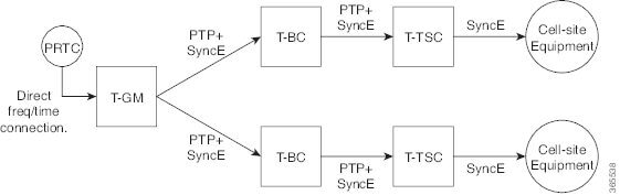
The G.8275.1 topology describes a network architecture for distributing precise frequency and time synchronization from a primary source down to cell-site equipment using PTP and SyncE.

The key components involved in the G.8275.1 topology process are:

  • Primary Reference Time Clock (PRTC): Provides the primary frequency and time reference signal.

  • T-GM: Receives timing from the PRTC and distributes synchronization signals using PTP and SyncE.

  • T-BC: Synchronizes to an upstream clock (T-GM or another T-BC) using PTP and SyncE, and provides synchronization to downstream clocks (T-BC or Telecom Slave Clock (T-TSC)).

  • T-TSC: Synchronizes to an upstream clock (T-BC) using PTP and SyncE, and provides frequency synchronization.

  • Cell-site Equipment: Receives frequency synchronization from the T-TSC.

Workflow

Figure 1. G.8275.1 topology

The ITU-T G.8275.1 standard defines this topology, a PTP profile for telecom networks for precise time and frequency synchronization in mobile operations.

The process involves these stages:

  1. The PRTC provides a direct frequency and time connection to the T-GM.

  2. The T-GM distributes PTP and SyncE synchronization signals downstream to T-BCs.

  3. T-BCs receive PTP and SyncE signals from an upstream clock (either the T-GM or another T-BC).

  4. T-BCs synchronize their internal clocks based on the received signals and distribute PTP and SyncE signals further downstream to other T-BCs or T-TSCs.

  5. T-TSCs synchronize their internal clocks based on the received signals.

  6. T-TSCs provide SyncE frequency synchronization to the cell-site Equipment.

  7. The Cell-site Equipment uses the received SyncE signal for frequency synchronization.

Result

This process ensures accurate delivery of precise frequency and time synchronization from a highly stable PRTC through the network to the end cell-site equipment.

PTP domains

G.8275.1 sets specific PTP domains to manage timing across the network once the synchronization model is in place.

A PTP domain is a network protocol management technique used in synchronized communication that:

  • provides phase synchronization and time-of-day alignment across network devices,

  • enables precise timing in various industrial and communication environments, and

  • supports configurations such as ITU-T G.8275.1 to use in telecom networks.

G.8275.1 networks:

  • do not allow devices that only forward PTP packets, such as non-participant devices and PTP transparent clocks.

  • support PTP domain numbers ranging from 24 to 43, with 24 being the default.

  • SyncE, though not mandatory, is commonly used to improve frequency stability for phase and time-of-day synchronization, a setup known as hybrid mode.

PTP messages and transport

To enable efficient timing synchronization, G.8275.1 specifies PTP message types and transport requirements.

G.8275.1 defines these PTP transport parameters:

  • Multicast PTP over Ethernet is required. You can use either the forwardable multicast MAC address (01-1B-19-00-00-00) or the non-forwardable multicast MAC address (01-80-C2-00-00-0E). The MAC address is selected per port through configuration.

  • You can use either one-step or two-step clock mode.

  • Two-way PTP operation is mandatory to deliver phase and time-of-day. The Delay-Request-Response mechanism measures propagation delay, while the peer-delay mechanism is not used.

  • The minimum packet rate is 8 packets-per-second for Announce messages and 16 packets per second for Sync, Follow-Up, Delay-Req and Delay-Resp messages.

  • Signaling and management messages are not used.


Note


G8275.1 is not supported on sub-interface, dot1q, or port-channel.


Best Master Clock Algorithm parameters and functions

G.8275.1 defines an alternate Best Master Clock Algorithm (BMCA) that each device uses to select a clock for synchronization and to determine the states of its local ports.

G.8275.1’s alternate BMCA parameters are:

  1. notSlave flag: The notSlave flag is a configurable boolean value for each port. It indicates whether a port can operate in secondary mode. When enabled on a port, the clock does not synchronize to any clock received on that port.

  2. Local priority: The Local priority is a per-port configuration. It resolves ties when a PTP clock chooses between clocks from different ports within a single network element. The network element's local clock also has a configurable local priority.

The G.8275.1 BMCA’s parameters are:

Clock characteristics and classification:

  • Clock Class: The profile defines clock classes for compliant clocks. The clock class depends on the clock type, its traceability, and its holdover status.

  • Clock Accuracy:

    0x21: Used by a T-GM locked to a PRTC.

    0xFE: Used by a T-GM in holdover or a T-BC.

  • Offset Scaled Log Variance:

    0x4E5D: Used by a T-GM locked to a PRTC.

    0xFFFF: Used by a T-GM in holdover or a T-BC.

Priority and tie-breaking parameters:

  1. Priority2: Used as in the original 1588v2 BMCA. Priority1 is not used.

  2. Local Priority: It is a per-port configuration. It resolves ties when a PTP clock chooses between clocks from different ports within a single network element. The network element's local clock also has a configurable local priority.

  3. Clock Identity: It acts as a tiebreaker between clocks, as in the original 1588v2 BMCA.

  4. Steps Removed: This value helps select between ports receiving the same clock, as in the original 1588v2 BMCA.

  5. Port Identity: The port identity acts as a tiebreaker between ports on the same clock.

A G.8275.1 clock ignores these values in received Announce messages:

  • alternate master, unicast, and the profile-specific members of the flag field,

  • control field, and

  • priority1

Configure the G.8275.1 profile

The G.8275.1 profile configuration includes:

Configure the T-GM

You can configure the router as a Telecom Grandmaster (T-GM), distributing timing to downstream devices using GNSS as the timing source.

A PTP Ordinary Clock (PTP-OC-T-GM) can synchronize itself with an upstream Grandmaster using frequency and 1PPS inputs. It typically uses these frequencies:

  • 10 MHz: Provides a stable frequency reference for clock synchronization.

  • 1PPS: Provides precise timing alignment to ensure accurate phase synchronization.

Procedure


Step 1

Use the configure command to enter into global configuration mode.

Example:

Router# configure

Step 2

Use the ptp clock ordinary domain 24 profile G.8275.1 command to enable PTP clock as an ordinary clock.

Example:

Router# ptp clock ordinary domain 24 profile telecom-g8275.1
  • domain 24: Sets the PTP domain number to 24. This ensures the router participates in the correct PTP instance, as multiple domains can coexist in a network.

  • profile telecom-g8275.1: Applies the G.8275.1 telecom profile, which is specifically designed for phase and time synchronization in telecom networks.

Step 3

Use the tod R0 ubx command to configure the Time of Day (ToD) source.

Example:

Router(config)# tod R0 ubx

Step 4

Use the input 1pps R0 command to configure the router to accept the 1PPS (Pulse Per Second) signal from the GNSS module connected to the R0 interface.

Example:

Router(config)# input 1pps R0

Step 5

Use the clock-port master-port master command to configure the PTP clock port as a primary port.

Example:

Router(config)# clock-port master-port master

Step 6

Use the transport ethernet multicast interface GigabitEthernet0/0/1 command to configure the PTP clock to use Ethernet for transport and specifies the physical interface.

Example:

Router(config)# transport ethernet multicast interface GigabitEthernet0/0/1

Step 7

Use the end command to exit the configuration mode and returns to the operational (privileged EXEC) mode.

Example:

Router(config)# end

Configure T-TSC

You can configure the router as a Telecom Time Slave Clock (T-TSC), distributing timing to downstream devices using GPS as the timing source.

Procedure


Step 1

Use the configure command to enter into global configuration mode.

Example:

Router# configure

Step 2

Use the ptp clock ordinary domain 24 profile G.8275.1 command to enable the PTP clock as an ordinary clock.

Example:

Router# ptp clock ordinary domain 24 profile telecom-g8275.1
  • domain 24: Sets the PTP domain number to 24. This setting ensures the router participates in the correct PTP instance, as multiple domains can coexist in a network.

  • profile telecom-g8275.1: Applies the G.8275.1 telecom profile, which is specifically designed for phase and time synchronization in telecom networks.

Step 3

Use the tod R0 ubx command to configure the Time of Day (ToD) source.

Example:

Router(config)# tod R0 ubx

Step 4

Use the output 1pps R0 command to configure the router to generate and provide a 1PPS (Pulse Per Second) signal on the R0 interface.

Example:

Router(config)# output 1pps R0

Step 5

Use the clock-port slave-port slave command to configure the PTP clock port as a secondary port.

Example:

Router(config)# clock-port slave-port slave

Step 6

Use the transport ethernet multicast interface GigabitEthernet0/0/1 command to configure the PTP clock to use Ethernet for transport and specifies the physical interface.

Example:

Router(config)# transport ethernet multicast interface GigabitEthernet0/0/1

Step 7

Use the end command to exit the configuration mode and return to the operational (privileged EXEC) mode.

Example:

Router(config)# end

Configure T-BC

You can configure the router as a Boundary Clock (BC) to receive time from an upstream clock and distribute it to downstream devices while maintaining precise synchronization.

Procedure


Step 1

Use the configure command to enter into global configuration mode.

Example:

Router# configure

Step 2

Use the ptp clock boundary domain 24 profile G.8275.1 command to enable the PTP clock as an Boundary Clock.

Example:

Router# ptp clock boundary domain 24 profile telecom-g8275.1
  • domain 24: Sets the PTP domain number to 24. This ensures that the router participates in the correct PTP instance, as multiple domains can coexist in a network.

  • profile telecom-g8275.1: Applies the G.8275.1 telecom profile, which is specifically designed for phase and time synchronization in telecom networks.

Step 3

Use the tod R0 cisco command to configure the Time of Day (ToD) source.

Example:

Router(config)# tod R0 ubx

Step 4

Use the output 1pps R0 command to configure the router to generate and provide a 1PPS (Pulse Per Second) signal on the R0 interface.

Example:

Router(config)# output 1pps R0

Step 5

Use the clock-port bc-port-1 command to function as part of the BC.

Example:

Router(config)# clock-port bc-port-1

Step 6

Use the transport ethernet multicast interface GigabitEthernet0/0/0 command to configure the PTP clock to use Ethernet for transport and specifies the physical interface.

Example:

Router(config)# transport ethernet multicast interface GigabitEthernet0/0/0

Step 7

Use the clock-port bc-port-2 command to function as part of the BC.

Example:

Router(config)# clock-port bc-port-2

Step 8

Use the transport ethernet multicast interface GigabitEthernet0/0/1 command to configure the PTP clock to use Ethernet for transport and specifies the physical interface.

Example:

Router(config)# transport ethernet multicast interface GigabitEthernet0/0/1

Step 9

Use the end command to exit the configuration mode and return to the operational (privileged EXEC) mode.

Example:

Router(config)# end

PTP clock commands

Use these commands to verify the G.8275.1 profile configuration.

Procedure


Step 1

Use the show ptp clock running command to view the PTP clock configuration.

Example:


Router# show ptp clock running
                      PTP Ordinary Clock [Domain 24] [Hybrid] [Profile: g8275.1]
         State          Ports          Pkts sent      Pkts rcvd      Redundancy Mode
         PHASE_ALIGNED  1              1176           2946           Hot standby
                               PORT SUMMARY
	                                                               PTP Master
Name  Tx Mode      Role         Transport    State        Sessions     Port Addr
slave mcast        slave        Ethernet     Slave        1            UNKNOWN

Step 2

Use the show ptp clock dataset default command to view the default PTP clock dataset.

Example:

Router# show ptp clock dataset default
CLOCK [Ordinary Clock, domain 24]
  Profile: g8275.1
  Two Step Flag: No
  Clock Identity: 0x6C:03:09:FF:FE:18:5F:03
  Number Of Ports: 1
  Priority1: 128
  Priority2: 128
  Local Priority: 128
  Domain Number: 24
  Slave Only: Yes
  Clock Quality:
    Class: 255
    Accuracy: Unknown
    Offset (log variance): 65535

Step 3

Use the show ptp clock dataset parent command to view the parent PTP clock dataset.

Example:

Router# show ptp clock dataset parent 
CLOCK [Ordinary Clock, domain 24]
  Profile: g8275.1
  Parent Clock Identity: 0x44:B6:BE:FF:FE:42:EF:13
  Parent Port Number: 0
  Parent Stats: No
  Observed Parent Offset (log variance): 0
  Observed Parent Clock Phase Change Rate: 0

  Grandmaster Clock:
    Identity: 0x44:B6:BE:FF:FE:42:EF:13
    Priority1: 128
    Priority2: 128
    Clock Quality:
      Class: 248
      Accuracy: Unknown
      Offset (log variance): 65535

Step 4

Use the show ptp port dataset port command to view the PTP port data set information.

Example:

Router# show ptp port dataset port
PORT [slave]
  Clock Identity: 0x6C:03:09:FF:FE:18:5F:03
  Clock Profile: g8275.1
  Transport Interface: GigabitEthernet0/0/1
  Port Number: 1
  Port State: Slave
  Min Delay Req Interval (log base 2): -4
  Peer Mean Path Delay: 0
  Announce interval (log base 2): -3
  Announce Receipt Timeout: 3
  Sync Interval (log base 2): -4
  Delay Mechanism: End to End
  Peer Delay Request Interval (log base 2): -4
  PTP version: 2
  Local Priority: 128
  Not-slave: False

Step 5

Use the show ptp wan stat stream 0 command to view the PTP WAN statistics.

Example:

Router# show ptp wan stat stream 0 
LOCK STATUS : PHASE LOCKED
SYNC Packet Stats
  Time elapsed since last packet: 0.0
  Configured Interval : -5, Acting Interval -5
  Tx packets : 0,  Rx Packets : 96215
  Last Seq Number : 30678,  Error Packets : 0
Delay Req Packet Stats
  Time elapsed since last packet: 0.0
  Configured Interval : -4, Acting Interval : -4
  Tx packets : 48107, Rx Packets : 0
  Last Seq Number : 0, Error Packets : 0
Delay Response Packet Stats
  Time elapsed since last packet: 0.0
  Configured Interval : -4, Acting Interval : -4
  Tx packets : 0, Rx Packets : 48107
  Last Seq Number : 48106, Error Packets : 0
Announce Packet Stats
  Time elapsed since last packet: 0.0
  Configured Interval : 1, Acting Interval : 1
  Tx packets : 0, Rx Packets :  1509
  Last Seq Number 1508 Error Packets 0
Signalling Packet Stats
  Time elapsed since last packet: 0.0
  Configured Interval : 0, Acting Interval : 0
  Tx packets : 12, Rx Packets : 12
  Last Seq Number : 0, Error Packets : 0
Current Data Set                             Units     Within tolerance? 
  Offset from master :  +0.000000000        seconds          Yes
  Mean Path Delay    :  +0.000000027        seconds          Yes
  Forward Path Delay :  +0.000000027        seconds          Yes
  Reverse Path Delay :  +0.000000028        seconds          Yes
  Steps Removed 1

Step 6

Use the show ptp wan tod command to view the PTP WAN time of the day.

Example:

Router# show ptp wan tod 
PTPd ToD information:

Time: 01/05/22 11:35:21

Step 7

Use the show network-clocks synchronization detail command to view the synchronization details of the network clocks.

Example:

Router# show network-clocks synchronization detail 
Automatic selection process : Enable
Equipment Clock : 2048 (EEC-Option1)
Clock State : Frequency Locked
Clock Mode : QL-Enable
ESMC : Enabled
SSM Option : 1 
T0 : GigabitEthernet0/0/1 
Hold-off (global) : 300 ms
Wait-to-restore (global) : 10 sec
Tsm Delay : 180 ms
Revertive : No
Force Switch: FALSE
Manual Switch: FALSE
Number of synchronization sources: 1
Squelch Threshold: QL-SEC
sm(netsync NETCLK_QL_ENABLE), running yes, state 1A
Last transition recorded: (begin)-> 2A (ql_mode_enable)-> 1A (src_added)-> 1A (sf_change)-> 1A (ql_change)-> 1A 
Nominated Interfaces
 Interface            SigType     Mode/QL      Prio  QL_IN  ESMC Tx  ESMC Rx
 Internal             NA          NA/Dis       251   QL-SEC    NA        NA       
*Gi0/0/1              NA          Sync/En      1     QL-PRC    -         - 

Step 8

Use the show esmc detail command to view the Ethernet Synchronization Messaging Channel details.

Example:

Router# show esmc detail 
Interface: GigabitEthernet0/0/0
  Administrative configurations:
    Mode: Asynchronous
    ESMC TX: Disable
    ESMC RX: Disable
    QL TX: -
    QL RX: -
  Operational status:
    Port status: UP
    QL Receive: QL-DNU
    QL Transmit: -
    QL rx overrided: -
    ESMC Information rate: 1 packet/second
    ESMC Expiry: 5 second
    ESMC Tx Timer: Stopped
    ESMC Rx Timer: Stopped
    ESMC Tx interval count: 1
    ESMC INFO pkts in: 777
    ESMC INFO pkts out: 1068
    ESMC EVENT pkts in: 0
    ESMC EVENT pkts out: 2

Step 9

Use the show platform hardware network-clocks command to view the chassis network clock details.

Example:

Router# show platform hardware network-clocks 
Chassis Manager Netclk Status
----------------
DPLL1 Status:
-------------
Bandwidth: 1.7 Hz
Phase Slope Limit: 7500 ns/s
Current PLL1 Mode: MANUAL NORMAL
Current Input Selected: REF7 (CLK_REC_25M_WAN2)
Current PLL1 Holdover Status: OFF
Current PLL1 Lock Status: ON
Router# show platform hardware network-clocks 
DPLL2 Status:
-------------
Bandwidth: 0.029 Hz
Phase Slope Limit: 750 ns/s
Current PLL2 Mode: TOP CLIENT (NCO)
Current Input Selected: none
Current PLL2 Holdover Status: OFF
Current PLL2 Lock Status: OFF
Router# show platform hardware network-clocks 
Current Input Status:
  REF0 (CLK_LOOPBACK1)   : OK
  REF1 (CLK_LOOPBACK2)   : OK
  REF2 ((TDM_SYNC_MB_PLL) : FAIL (SCM, CFM, GST, PFM failed)
  REF3 (RSV_2_M_PLL)      : FAIL (SCM, CFM, GST, PFM failed)
  REF4 (CLK_PPS_GPS_PLL)  : FAIL (SCM, CFM, GST, PFM failed)
  REF5 (CLK_PPS_MB_PLL)   : FAIL (SCM, CFM, GST, PFM failed)
  REF6 (CLK_REC_25M_WAN1) : FAIL (SCM, CFM, GST, PFM failed)
  REF7 (CLK_REC_25M_WAN2) : OK
  REF8 (CLK20M_OCXO)      : OK
  REF9 (RSV_1_MB_PLL)     : FAIL (SCM, CFM, GST, PFM failed)
Router# show platform hardware network-clocks 

  REF0 Freq Configured   : 25 Mhz
  REF1 Freq Configured   : 25 Mhz
  REF2 Freq Configured   : 8 Khz
  REF3 Freq Configured   : 10 Mhz
  REF4 Freq Configured   : 1 Hz
  REF5 Freq Configured   : 1 Hz
  REF6 Freq Configured   : 25 Mhz
  REF7 Freq Configured   : 25 Mhz
  REF8 Freq Configured   : 20 Mhz
  REF9 Freq Configured   : 25 Mhz