Introduction
 Caution |
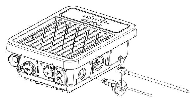
The Cisco Wireless Gateway for LoRaWAN must be installed by professional networking or computer technicians. |
For configuration information, refer to the Configuring Virtual-LPWA section of the Cisco IR800 Integrated Services Router Software Configuration Guide on Cisco.com:


 Feedback