Multicast Service Reflection Overview
The Cisco Multicast Service Reflection feature provides the capability for users to translate externally received multicast or unicast destination addresses to multicast or unicast addresses that conform to their organization’s internal addressing policy. Using this feature, users do not need to redistribute unicast routes from external sources at the translation boundary into their network infrastructure for Reverse Path Forwarding (RPF) to work properly. In addition, users can receive identical feeds from two ingress points in the network and route them independently.
Prerequisites for Implementing Multicast Service Reflection
-
Configure your multicast-enabled network with the necessary infrastructure to run either Protocol Independent Multicast Sparse Mode (PIM-SM), Bidirectional PIM (bidir-PIM), or PIM Source Specific Multicast (PIM-SSM). The configuration process may include configuring RPs, interface boundaries, or SSM ranges.
-
Confirm that the virtual interface for multicast service reflection (Vif1 interface) is installed in your border router and the Multicast Service Reflection application is installed and operational.
-
Each active receiver must initiate an Internet Group Management Protocol (IGMP) join to the multicast group that is defined on the router in the PIM domain.
Restrictions for Implementing Multicast Service Reflection
-
When translating groups of multicast packets that are destined for the same multicast group but are originating from different sources, as in the case when using PIM-SSM, all multicast packets destined for a particular SSM group will get mapped to a single (S, G) after translation has occurred. For example, if (10.1.1.1, 232.1.1.1) and (10.1.1.2, 232.1.1.1) need to be translated, they will appear as a single entry, for example, (92.168.1.2, 232.239.1.1), where 192.168.1.2 is an IP address that resides in the Vif1 IP subnet.
-
PIM/IGMP control packets are not translated.
-
The following types of translation are not supported in Cisco IOS XE software:
-
Unicast-to-Multicast Destination Translation
-
Unicast-to-Multicast Destination Splitting
-
-
The use of a sub-interface as an input-interface has not been tested on platforms that are based on mcp_dev.
Information About Implementing Multicast Service Reflection
This section contains the following:
Benefits of Implementing Multicast Service Reflection
-
Allows users to translate externally received multicast or unicast destination addresses to multicast or unicast addresses that conform to their company’s internal addressing policy. This allows the seperation of the private addressing scheme used by the content provider from the public addressing used by the service provider. The following types of translations are supported:
-
Multicast-to-Multicast Destination Translation
-
Multicast-to-Unicast Destination Translation
-
Multicast-to-Multicast Destination Splitting
-
Multicast-to-Unicast Destination Splitting
-
-
Provides logical separation between private and public multicast networks.
-
Provides the flexibility to forward multicast packets--translated or untranslated--out the same outgoing interface.
-
Provides redundancy by allowing users to get identical feeds from two ingress points in the network and route them independently.
-
Allows users to use the subnet of their choice to be the source network and scope it appropriately.
Rendezvous Point (RP)
A Rendezvous Point (RP) is a role that a router performs when operating in PIM-SM or bidirectional PIM. An RP is required only in networks running PIM-SM or bidirectional PIM. In PIM-SM, only network segments with active receivers that have explicitly requested multicast data will be forwarded the traffic.
An RP acts as the meeting place for sources and receivers of multicast data. In a PIM-SM network, first hop designated routers with directly connected sources initially send their traffic to the RP. This traffic is then forwarded to receivers down a shared distribution tree. By default, when the last hop router with a directly connected receiver receives traffic from the shared tree, it immediately performs a shortest path tree switchover and sends a Join message towards the source, creating a source-based distribution tree between the source and the receiver.
PIM Sparse Mode
PIM sparse mode (PIM-SM) uses a pull model to deliver multicast traffic. Only network segments with active receivers that have explicitly requested the data will receive the traffic.
Unlike dense mode interfaces, sparse mode interfaces are added to the multicast routing table only when periodic Join messages are received from downstream routers, or when a directly connected member is on the interface. When forwarding from a LAN, sparse mode operation occurs if an RP is known for the group. If so, the packets are encapsulated and sent toward the RP. When no RP is known, the packet is flooded in a dense mode fashion. If the multicast traffic from a specific source is sufficient, the first hop router of the receiver may send Join messages toward the source to build a source-based distribution tree.
PIM-SM distributes information about active sources by forwarding data packets on the shared tree. Because PIM-SM uses shared trees (at least, initially), it requires the use of a rendezvous point (RP). The RP must be administratively configured in the network.
In sparse mode, a router assumes that other routers do not want to forward multicast packets for a group, unless there is an explicit request for the traffic. When hosts join a multicast group, the directly connected routers send PIM Join messages toward the RP. The RP tracks multicast groups. Hosts that send multicast packets are registered with the RP by the first hop router of that host. The RP then sends Join messages toward the source. At this point, packets are forwarded on a shared distribution tree. If the multicast traffic from a specific source is sufficient, the first hop router of the host may send Join messages toward the source to build a source-based distribution tree.
First-hop designated routers with directly connected sources register with the RP and then data is forwarded down the shared tree to the receivers. The edge routers learn about a particular source when they receive data packets on the shared tree from that source through the RP. The edge router then sends PIM (S, G) Join messages toward that source. Each router along the reverse path compares the unicast routing metric of the RP address to the metric of the source address. If the metric for the source address is better, it will forward a PIM (S, G) Join message toward the source. If the metric for the RP is the same or better, then the PIM (S, G) Join message will be sent in the same direction as the RP. In this case, the shared tree and the source tree would be considered congruent.
If the shared tree is not an optimal path between the source and the receiver, the routers dynamically create a source tree and stop traffic from flowing down the shared tree. This behavior is the default behavior in Cisco IOS software. Network administrators can force traffic to stay on the shared tree by using the Cisco IOS ip pim spt-threshold infinity command.
PIM-SM scales well to a network of any size, including those with WAN links. The explicit join mechanism prevents unwanted traffic from flooding the WAN links.
Vif1 Interface
The Vif1 interface is similar to a loopback interface--it is a logical IP interface that is always up when the router is active.
The Vif1 interface needs to reside on its own unique subnet, and that subnet should be advertised in the Interior Gateway Protocol (IGP) updates (RIP, EIGRP, OSPF, ISIS).
The Vif1 interface maintains information about the input interface, private-to-public mgroup mappings, mask length, which defines your pool range, and the source of the translated packet.
Multicast Service Reflection Application
Cisco multicast service reflection is an application running in Cisco IOS software interrupt level switching that processes packets forwarded by Cisco IOS software to the Vif1 interface. Unlike IP multicast Network Address Translation (NAT), which only translates the source IP address, the IP reflect service translates both source and destination addresses. Multicast service reflection is especially useful when users that have not yet moved to the new multicast group still need to receive the untranslated stream.
Multicast service reflection is implemented using an interface CLI statement. Each configured multicast service reflection CLI statement establishes a packet match and rewrite operation acting on packets sent by Cisco IOS unicast or multicast packet routing onto the Vif1 interface. The matched and rewritten packet is sent back into Cisco IOS unicast or multicast packet routing, where it is handled like any other packet arriving from an interface.
The Vif1 interface is a receiver for the original stream and makes it appear that the new stream is coming from a source directly connected to the Vif1 subnet. The Vif1 interface is a Designated Router (DR) for active sources and registers with the appropriate RP.
More than one multicast service reflection operation can be configured to match the same packets, which allows you to replicate the same received traffic to multiple destination addresses.
How to Implement Multicast Service Reflection
This section contains the following:
Configuring Multicast Service Reflection
Perform this task to configure multicast service reflection.
Procedure
| Command or Action | Purpose | |
|---|---|---|
|
Step 1 |
enable Example: |
Enables privileged EXEC mode.
|
|
Step 2 |
configure terminal Example: |
Enters global configuration mode. |
|
Step 3 |
ip multicast-routing [distributed ] Example: |
Enables IP multicast routing.
|
|
Step 4 |
interface type number Example: |
Enters interface configuration mode for the specified interface type and number. |
|
Step 5 |
ip pim sparse-mode Example: |
Enables PIM sparse mode on the interface. |
|
Step 6 |
no shutdown Example: |
Enables an interface. |
|
Step 7 |
exit Example: |
Exits interface configuration mode, and returns to global configuration mode. |
|
Step 8 |
Repeat Steps 4 through 7 for each PIM interface. |
-- |
|
Step 9 |
interface Vif1 Example: |
Enters interface configuration mode for the Vif1 interface. |
|
Step 10 |
ip address ip-address mask [secondary ] Example: |
Sets a primary or secondary IP address for an interface. |
|
Step 11 |
ip pim sparse-mode Example: |
Enables PIM sparse mode on an interface. |
|
Step 12 |
ip service reflect input-interface destination destination-address to new-destination-address mask-len number source new-source-address Example: |
Matches and rewrites multicast packets routed onto the Vif1 interface.
|
|
Step 13 |
ip igmp static-group {* | group-address [source {source-address | ssm-map }]} Example: |
Configures the router to be a statically connected member of the specified group on the interface, and forwards traffic destined for the multicast group onto the interface.
|
|
Step 14 |
end Example: |
Exits interface configuration mode, and returns to privileged EXEC mode. |
Configuration Examples for Multicast Service Reflection
See the following examples.
Example Multicast-to-Multicast Destination Translation
The following example shows how to implement multicast service reflection (multicast-to-multicast destination translation) in a service provider network. Multicast-to-Multicast Destination Translation allows service providers to translate externally received content provider multicast destination addresses to multicast destination addresses that conform to the service provider’s internal addressing policy.
This example uses the topology illustrated in the figure.
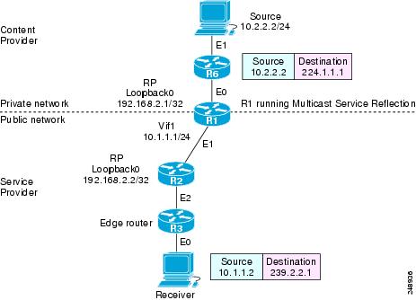
In this example topology, a content provider is sending financial market information to a service provider, which in turn is sending that information to active receivers (brokerage houses). The service provider may be receiving market data from multiple content providers.
Router R1 is an edge router in the service provider’s PIM domain.
Router R1 has a loopback interface and is acting as the RP for the 224.1.1.0/24 address range.
Router R1 has a Vif1 interface and is running the multicast service reflection application.
Router R2 has a loopback interface and is acting as the RP for the 239.2.2.0/24 address range.
Enter these commands on the router running the multicast service reflection application (R1):
!
configure terminal
	ip multicast-routing
	interface <all IP numbered interfaces>
	ip pim sparse-mode
	no shutdown
	!
	! Configure the loopback interface for the Service Provider RP
!
	interface loopback 0
	ip address 192.168.2.1 255.255.255.255
	ip pim sparse-mode
	!
	ip pim rp-address 192.168.2.1 mcast-content-provider-groups override
	ip pim rp-address 192.168.2.2 mcast-service-provider-groups override
	ip access-list standard mcast-content-provider-groups permit 224.1.1.0 0.0.0.255
	ip access-list standard mcast-service-provider-groups permit 239.2.2.0 0.0.0.255
	!
! Configure the Vif1 virtual interface for multicast service reflection
!
	interface Vif1
	ip address 10.1.1.1 255.255.255.0
	ip pim sparse-mode
	ip service reflect Ethernet 0 destination 224.1.1.0 to 239.2.2.0 mask-len 24 source 10.1.1.2
	ip igmp static-group 224.1.1.0
	ip igmp static-group 224.1.1.1
	ip igmp static-group 224.1.1.2
	ip igmp static-group 224.1.1.3
	.
	.
	.
	ip igmp static-group 224.1.1.255
Enter these commands on the router that is the RP in the service provider network (R2):
ip multicast-routing
interface <all IP numbered interfaces>
	ip pim sparse-mode
	no shutdown
!
	interface loopback 0
	ip address 192.168.2.2 255.255.255.255
	ip pim sparse-mode
!
ip pim rp-address 192.168.2.2 mcast-service-provider-groups override
ip access-list standard mcast-service-provider-groups permit 239.2.2.0 0.0.0.255
!
Enter these commands on all the other routers in the service provider network (R3):
ip multicast-routing
	interface <all IP numbered interfaces>
	ip pim sparse-mode
	no shutdown
!
	ip pim rp-address 192.168.2.2 mcast-service-provider-groups override
	ip access-list standard mcast-service-provider-groups permit 239.2.2.0 0.0.0.255
	end
Example Multicast-to-Unicast Destination Translation
The following example shows how to implement multicast service reflection (multicast-to-unicast destination translation) in a service provider network. Multicast-to-Unicast Destination Translation allows service providers to translate externally received content provider multicast destination addresses to unicast destination addresses that conform to the service provider’s internal addressing policy.
This example uses the topology illustrated in the figure.
In this example topology, a content provider is sending financial market information to a service provider, which in turn is sending that information to active receivers (brokerage houses). The service provider may be receiving market data from multiple content providers.
Router R1 is an edge router in the service provider’s PIM domain.
Router R1 has a loopback interface and is acting as the RP for the 224.1.1.0/24 address range.
Router R1 has a Vif1 interface and is running the multicast service reflection application.
Routers R2 and R3 are non PIM enabled routers running unicast routing only in the service provider network.
Enter these commands on the router running the multicast service reflection application (R1):
configure terminal
	ip multicast-routing
	interface <all IP numbered interfaces>
	ip pim sparse-mode
	no shutdown
	!
! Configure the loopback interface for the Service Provider RP
!
	interface loopback 0
	ip address 192.168.2.1 255.255.255.255
       ip pim sparse-mode
	!
	ip pim rp-address 192.168.2.1 mcast-content-provider-groups override
	ip access-list standard mcast-content-provider-groups permit 224.1.1.10 0.0.0.255
	!
! Configure the Vif1 virtual interface for multicast service reflection
!
	interface Vif1
	ip address 10.1.1.1 255.255.255.0
	ip pim sparse-mode
	ip service reflect Ethernet 0 destination 224.1.1.0 to 10.3.3.0 mask-len 24 source 10.1.1.2
	end
Example Multicast-to-Multicast Destination Splitting
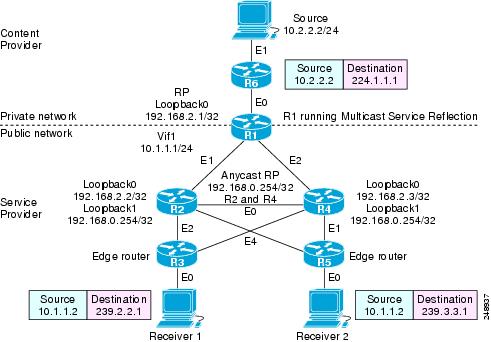
The following example shows how to implement multicast service reflection (multicast-to-multicast destination splitting where the multicast single stream is converted into two unique multicast streams) in a service provider network. Multicast-to-Multicast Destination Splitting allows service providers to translate externally received content provider multicast destination addresses to multiple multicast destination addresses that conform to the service provider’s internal addressing policy.
This example uses the topology illustrated in the figure.
In this example topology, a content provider is sending financial market information to a service provider, which in turn is sending that information to active receivers (brokerage houses). The service provider may be receiving market data from multiple content providers.
Router R1 is an edge router in the service provider’s PIM domain.
Router R1 has a loopback configured and is acting as an RP for the 224.1.1.0/24 address range.
Router R1 has a Vif1 interface and is running the multicast service reflection application.
Routers R2 and R4 have multiple loopback interfaces and are acting as anycast RPs for the 239.2.2.0 and 239.3.3.0 address ranges.
Router R3 and R5 are edge routers in the service provider’s PIM domain.
Enter these commands on the router running the multicast service reflection application (R1):
configure terminal
	ip multicast-routing
	interface <all IP numbered interfaces>
	ip pim sparse-mode
	no shutdown
	!
! Configure the loopback interface for the Service Provider RP
	interface loopback 0
	ip address 192.168.2.1 255.255.255.255
	ip pim sparse-mode
	ip pim rp-address 192.168.2.1 mcast-content-provider-groups override
	ip pim rp-address 192.168.0.254 mcast-service-provider-groups override
	ip access-list standard mcast-content-provider-groups permit 224.1.1.0 0.0.0.255
	ip access-list standard mcast-service-provider-groups permit 239.2.2.0 0.0.0.255
	ip access-list standard mcast-service-provider-groups permit 239.3.3.0 0.0.0.255
	!
! Configure the Vif1 virtual interface for multicast service reflection
	interface Vif1
	ip address 10.1.1.1 255.255.255.0
	ip pim sparse-mode
	ip service reflect Ethernet 0 destination 224.1.1.0 to 239.2.2.0 mask-len 24 source 10.1.1.2
	ip service reflect Ethernet 0 destination 224.1.1.0 to 239.3.3.0 mask-len 24 source 10.1.1.2
	ip igmp static-group 224.1.1.0
       ip igmp static-group 224.1.1.1
	ip igmp static-group 224.1.1.2
	ip igmp static-group 224.1.1.3
	ip igmp static-group 224.1.1.254
Enter these commands on the R2 router that is an anycast RP in the service provider network:
ip multicast-routing
interface <all IP numbered interfaces>
	ip pim sparse-mode
	no shutdown
	interface loopback 0
	ip address 192.168.2.2 255.255.255.255
	ip pim sparse-mode
	interface loopback 1
	description --- Anycast RP ---
	ip address 192.168.0.254 255.255.255.255
	ip pim sparse-mode
	ip msdp peer 192.168.2.3 connect-source Loopback0
	ip msdp originator-id Loopback0
	ip pim rp-address 192.168.0.254 mcast-service-provider-groups override
	ip access-list standard mcast-service-provider-groups permit 239.2.2.0 0.0.0.255
	ip access-list standard mcast-service-provider-groups permit 239.3.3.0 0.0.0.255
Enter these commands on the R4 router that is an anycast RP in the service provider network:
ip multicast-routing
interface <all IP numbered interfaces>
	ip pim sparse-mode
	no shutdown
	!
	interface loopback 0
	ip address 192.168.2.3 255.255.255.255
	ip pim sparse-mode
	interface loopback 1
	ip address 192.168.0.254 255.255.255.255
	ip pim sparse-mode
!
ip pim rp-address 192.168.0.254 mcast-service-provider-groups override
ip access-list standard mcast-service-provider-groups permit 239.2.2.0 0.0.0.255
ip access-list standard mcast-service-provider-groups permit 239.3.3.0 0.0.0.255
!
ip msdp peer 192.168.2.2 connect-source Loopback0
ip msdp originator-id Loopback0
Enter these commands on the R3 and R5 routers in the service provider network:
ip multicast-routing
	ip pim rp-address 192.168.0.254 mcast-service-provider-groups override
	ip access-list standard mcast-service-provider-groups permit 239.2.2.0 0.0.0.255
permit 239.3.3.0 0.0.0.255
	!
Example Multicast-to-Unicast Destination Splitting
The following example shows how to implement multicast service reflection (multicast-to-unicast destination splitting where the multicast single stream is converted into two unique unicast streams) in a service provider network. Multicast-to-Unicast Destination Splitting allows service providers to translate externally received content provider multicast destination addresses to multiple unicast destination addresses that conform to the service provider’s internal addressing policy.
This example uses the topology illustrated in the figure.
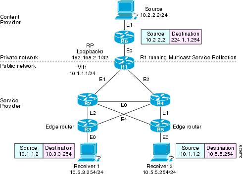
In this example topology, a content provider is sending financial market information to a service provider, which in turn is sending that information to active receivers (brokerage houses). The service provider may be receiving market data from multiple content providers.
Router R1 is an edge router in the service provider’s PIM domain.
Router R1 is acting as a RP for the 224.1.1.0/24 address range.
Router R1 has a Vif1 interface and is running the multicast service reflection application.
Routers R2, R3, R4 and R5 are not PIM enabled and are running unicast routing only in the service provider network.
Enter these commands on the router running the multicast service reflection application (R1):
configure terminal
	ip multicast-routing
interface <all IP numbered interfaces>
	ip pim sparse-mode
	no shutdown
	!
! Configure the loopback interface for the Service Provider RP
!
	interface loopback 0
	ip address 192.168.2.1 255.255.255.255
ip pim sparse-mode
	!
	ip pim rp-address 192.168.2.1 mcast-content-provider-groups override
	ip access-list standard mcast-content-provider-groups permit 224.1.1.0 0.0.0.255
	!
! Configure the Vif1 virtual interface for multicast service reflection
!
	interface Vif1
	ip address 10.1.1.1 255.255.255.0
	ip pim sparse-mode
	ip service reflect Ethernet 0 destination 224.1.1.0 to 10.3.3.0 mask-len 24 source 10.1.1.2
ip service reflect Ethernet 0 destination 224.1.1.0 to 10.5.5.0 mask-len 24 source 10.1.1.2
	ip igmp static-group 224.1.1.0
	ip igmp static-group 224.1.1.1
	ip igmp static-group 224.1.1.2
	ip igmp static-group 224.1.1.3
	.
	.
	.
	ip igmp static-group 224.1.1.255
!
end Feedback