Connecting to the CGR 1000
You can use Device Manager in the following ways:
-
Operating with IoT-FND—–When you have IoT-FND operating in the network, you can connect to that system with Device Manager to download and update work orders. Work orders allow Device Manager to view status and perform tasks on the CGR 1000. To operate in conjunction with IoT-FND, follow the steps in Setting Up the IoT-FND Connection.
-
Operating without IoT-FND—When you do not have IoT-FND operating in the network or do not want to connect to that system, use Device Manager to connect directly to a CGR 1000 by either WiFi (with valid SSID and passphrase) or Ethernet to view status and perform tasks on the CGR 1000.
Connecting to the Router with a Work Order
Before connecting to the router with a work order, you should be familiar with the information in Managing Work Orders.
To connect to the router with a work order, select a work order from the list on the Device Manager opening page and click Connect .
 Note |
The IR809 must have IPv6 option enabled to connect with work order. |
Manually Connecting to the Router
You can connect to a CGR 1000 by either Ethernet or WiFi. WiFi connectivity ensures WPA Layer 2 security on data traffic between Device Manager and the router, after association and the key handshake complete. The Ethernet connection is secured by HTTPS only.
Connect to the Device Manager by employing one of the following methods:
-
Auto Discovered IPv6 address (preferred method for the field)
-
IPv4 address (such as 128.128.128.128)
-
IPv6 address (such as fe80::d81f:6402:2ae4:4ea8)
To connect to the Device Manager manually:
SUMMARY STEPS
- On the Device Manager opening page, click Connect Without Work Order .
- In the Connect to Device dialog box, select the Device Type: CGR1120 or CGR1240 .
- Select the Connection Type: Over WiFi , Over Ethernet , or Auto Detect .
- Enter the router IP address and port, or select the check box to auto-discover the IP address.
- (WiFi only) Enter the SSID and pass phrase.
- Enter the user name and password.
- Click Connect . The Device Manager main page appears.
DETAILED STEPS
| Step 1 |
On the Device Manager opening page, click Connect Without Work Order . 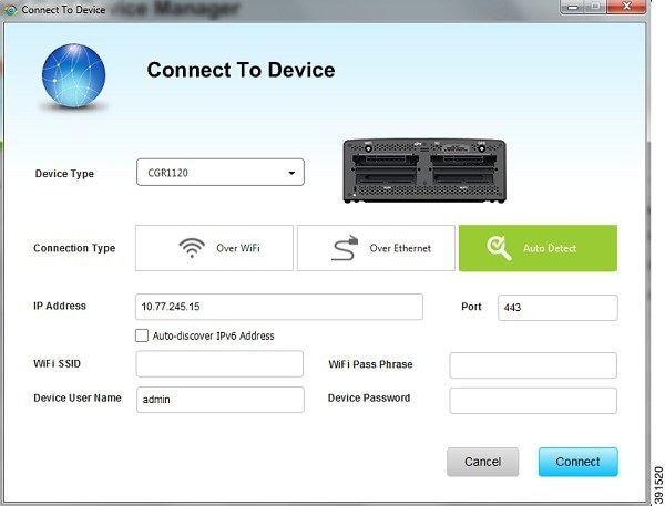 |
||
| Step 2 |
In the Connect to Device dialog box, select the Device Type: CGR1120 or CGR1240 . |
||
| Step 3 |
Select the Connection Type: Over WiFi , Over Ethernet , or Auto Detect . |
||
| Step 4 |
Enter the router IP address and port, or select the check box to auto-discover the IP address.
|
||
| Step 5 |
(WiFi only) Enter the SSID and pass phrase. |
||
| Step 6 |
Enter the user name and password. |
||
| Step 7 |
Click Connect . The Device Manager main page appears. |

 Feedback