
Application
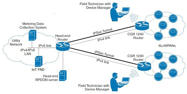
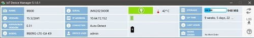
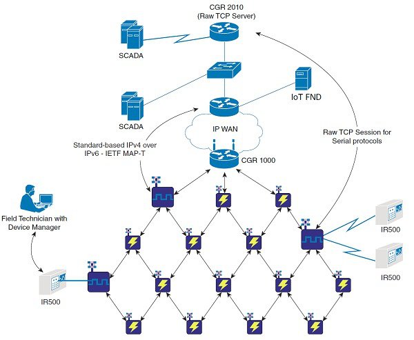
Device Manager is a Windows-based application that field technicians can use to manage the CGR 1000 running Cisco IOS over WiFi or Ethernet. Beginning with Release 4.1, Device Manager supports management of the IR509, which supplies RF mesh connectivity to IPv4 and serial Internet of Things (IoT) devices (for example, recloser controls, capacitor bank controls, voltage regulator controls, and other remote terminal units). From Release 5.1, Device Manager supports management of the Cisco 800 Series Industria Integrated Services Routers (IR800) and IR510.
Cisco IoT Field Network Director (Cisco IoT-FND) manages multiple CGR 1000, IR800, and IR500 devices, whereas Device Manager connects and manages a single device at a time.
-
Device Manager can manage CGR 1000 routers in Connected Grid field deployments operating with or without IoT-FND:
-
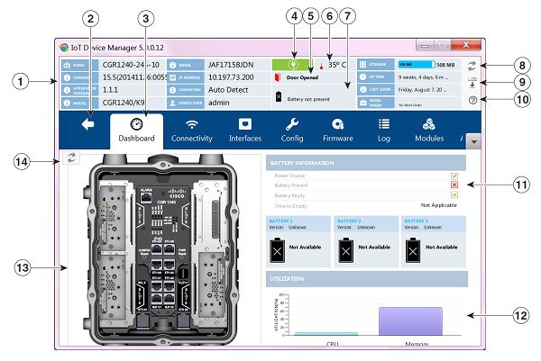
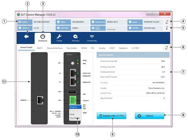
When operating with IoT-FND, a Device Manager user can retrieve work orders from the system as well as perform all supported tasks on the main page (see Figure 1) except as limited by the privilege level that the administrator configures on the router for that user.
-
When operating without IoT-FND, the Device Manager user does not have access to work orders; however, the user can perform all supported tasks on the main page except as limited by the user’s privilege level.
-
-
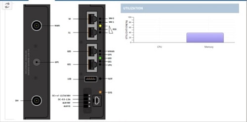
Device Manager can manage IR800 routers in Connected Grid field deployments operating with or without IoT-FND:
-
When operating with IoT-FND, a Device Manager user can retrieve work orders from the system as well as perform all supported tasks on the main page (see Device Manager and IR800) except as limited by the privilege level that the administrator configures on the router for that user.
-
When operating without IoT-FND, the Device Manager user does not have access to work orders; however, the user can perform all supported tasks on the main page except as limited by the user’s privilege level.
-
-
Device Manager can manage IR500 gateways in Connected Grid field deployments operating with or without IoT-FND:
-
When operating with IoT-FND, a Device Manager user can retrieve work orders from the system as well as perform all supported tasks on the main page (see Figure 1).
IR500 devices use CoAP Simple Management Protocol (CSMP) for communicating with IoT-FND. The IR500 gateways regularly report inventory metrics to IoT-FND using CSMP. IoT-FND stores the reported properties and metrics.
-
When operating without IoT-FND, the Device Manager user does not have access to work orders. The user can view device settings and status but cannot make configuration changes or send data to IoT-FND.
-
 Feedback