Install Cisco Catalyst 8000V in NFVIS Environment

Cisco Enterprise Network Function Virtualization Infrastructure Software (Cisco Enterprise NFVIS) is a Linux-based infrastructure software. It helps service providers and enterprises dynamically deploy virtualized network functions, including a virtual router, firewall, and WAN acceleration, on a supported Cisco device.

The Cisco Enterprise NFVIS solution helps service providers and enterprises convert critical network functions into software, making it possible to rapidly deploy and manage network services across diverse and distributed locations.

Cisco NFVIS version 4.4 or later is required for Cisco Catalyst 8000V installation.

This chapter specifies the installation workflow for Cisco Catalyst 8000V in NFVIS. This chapter also provides information on upgrading a Cisco Integrated Services Virtual Router (ISRv) running on NFVIS to Cisco Catalyst 8000V.

Supported hardware

The tables in this section list all hardware requirements for installing Cisco Catalyst 8000V in NFVIS.

Supported hardware platforms running NFVIS

See this list for all hardware platforms supported for this installation.

  • Cisco 5400 Series Enterprise Network Compute System (ENCS)

  • Cloud Services Platform 5000 Series (CSP)

  • Cisco 8200 UCPE Series

Supported network interface modules

See this list of all supported network interface modules (NIMs) for this installation.

  • NIM-4G-LTE-VZ

  • NIM-4G-LTE-ST

  • NIM-4G-LTE-NA

  • NIM-4G-LTE-GA

  • NIM-4G-LTE-LA

  • NIM-LTEA-EA

  • NIM-LTEA-LA

  • NIM-1MFT-T1/E1

  • NIM-2MFT-T1/E1

  • NIM-4MFT-T1/E1

  • NIM-8MFT-T1/E1

  • NIM-1CE1T1-PRI

  • NIM-2CE1T1-PRI

  • NIM-8CE1T1-PRI

  • NIM-16A

  • NIM-24A

  • NIM-VA-B

  • NIM-VAB-A

  • NIM-VAB-M

  • NIM-4SHDSL-EA

  • NIM-1GE-CU-SFP

  • NIM-2GE-CU-SFP

  • NIM-ES2-8-P

  • NIM-ES2-8 NIM-ES2-4

Supported network interface cards

The table lists all network interface cards (NICs) supported for this installation.

Hardware

VNIC

ENCS

virtio, igbvf and i40evf

UCPE

virtio, igbvf and ixgbevf

CSP

  • virtio, igbvf - supported from Cisco IOS XE 17.4.1

  • i40evf - supported from Cisco IOS XE 17.4.1 to 17.8.x

  • ConnectX-5VF and iavf - supported from Cisco IOS XE 17.9.1

  • Ixgbe - supported from Cisco IOS XE 17.10.1

Supported profiles

See the list of profiles supported for this installation.

  • Mini – 1vCPU

  • Small – 2vCPU

  • Medium – 4vCPU

  • Large – 4vCPU


Note


Cisco Catalyst 8000V works as a low latency VM and performs as expected with dedicated vCPU cores.


Installing the virtual machines

Summary

From the Cisco IOS XE 17.4.1 release, you can either freshly install a Cisco Catalyst 8000V VM in NFVIS, or you can upgrade from a Cisco ISRv to Cisco Catalyst 8000V.

Workflow

To perform Cisco Catalyst 8000V installtion on NFVIS, proceed through each stage in this workflow.

  1. Register a VM image: Copy or download the VM image to the NFVIS server. Alternatively, host the image on an HTTP or HTTPS server. After downloading the file, register the image using the registration API. This API allows you to specify the file path on the HTTP or HTTPS server where the tar.gz file is hosted. Registering the image is a one-time activity. After registration is active, multiple VMs can be deployed by using the registered image.
  2. Create a custom profile: Optionally create a custom profile for the VM image. This action is beneficial if the profiles defined in the image file do not match the requirements. Custom profiles provide specific profiling details for a VM image, such as the number of virtual CPUs on which the VM runs, the amount of virtual memory the VM consumes. Depending on the topology, additional networks and bridges can be created during the deployment.
  3. Deploy the VM: Use the deployment API to deploy the VM. This API provides values to the parameters that are passed to the system during deployment. Depending on the VM that is deployed, some parameters are mandatory and others are optional. For more details about the APIs, see VM Lifecycle Management APIs .
  4. Manage and monitor the VM: Use APIs and commands to access the VM status and debug logs. Using the VM management APIs, you can start, stop, or reboot a VM, and view the statistics for a VM, such as CPU usage. You can change or update a VM profile to one of the existing profiles in the image file, or create a new custom profile for the VM. You can also add or update vNICs on a VM.

Install the VM in NFVIS (Release 4.5.1 and Later)

Install Cisco Catalyst 8000V in NFVIS Environment

If you want to install Cisco Catalyst 8000V on NFVIS version 4.5.1 or later, follow the procedures that follow this section.

To install Cisco Catalyst 8000V on earlier releases of NFVIS, see Install Cisco Catalyst 8000V in NFVIS Environment.

Upload the installation file in NFVIS

Perform these steps to upload the installation file in NFVIS.

Procedure


Step 1

Log in to the NFVIS Portal.

Step 2

In the portal, Configuration > Virtual Machine > Images > Image Repository.

Step 3

Upload the installation file by performing one of these two options:

  • Selct Local > Select File. From your device, locate and select the installation file. The upload completes.

  • Select Remote.

Step 4

If you chose Remote, provide these details:

  1. Image Name : Specify the name of the image file in this field.

  2. Protocol : Choose the protocol from this drop-down list.

  3. IP Address : Specify the IP address for the remote location in this field.

  4. Port : Specify the port for the remote location in this field.

  5. Image File Path : Specify the file path to the installation file in this field.


Create a network

Procedure


Step 1

In the NFVIS Portal, choose Configuration > Virtual Machine > Networking > Networks.

Step 2

To create a new network, click the + icon.

Step 3

In the Add Network area, enter these details:

  1. Network: Choose the network from this drop-down list.

  2. Mode: Enter the mode in which the VNF will boot.

  3. VLAN: Choose the VLAN for the VM.

  4. VLAN-Range: Enter the range of VLAN for your VM.

  5. Native VLAN: Choose the native VLAN for your VM from this field.

  6. Bridge: The Layer 2 domain between virtual network interface controllers (vNICs) of VMs. Choose either the Existing or the Create New radio button.

  7. Interface: Choose the interface from this field for your VM.

    Note


    Single Root Input/Output Virtualization (SR-IOV) is not supported in this installation.

Step 4

Click Submit .


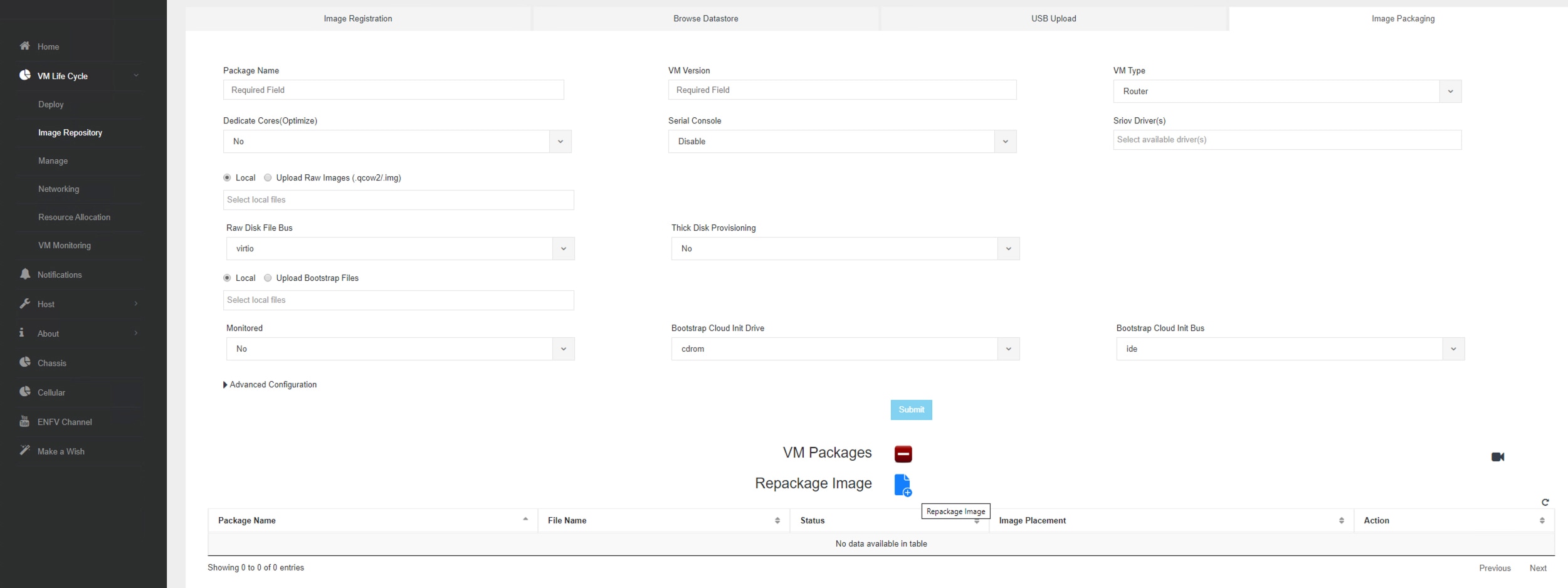
Create a VM package

Procedure


Step 1

In the NFVIS portal, choose Configuration > Virtual Machine > Images > Image Packaging.

Step 2

To create a VM package, click the + icon.

Step 3

In the Image Packaging area, configure these details.

Field

Description

Name

The name associated with the VM packaging.

Version

The version of the package.

VM Type

The type of the VM for which you’re creating the package.

Dedicate Cores (Optimize)

The number of dedicated cores a container requires. By default, the value is False .

Serial Console

Use this field to enable or disable access through the serial console. By default, the value is Disable .

SRIOV Driver

The SRIOV driver supported by the VM interfaces.
Local

Use this option if the image you want to bundle is available in the intdatastore.

Upload Raw Images

Use this option to upload an image from your local machine for packaging.

Raw Disk File Bus

Choose the root disk image bus from this drop-down list.

Thick Disk Provisioning

Choose true from the drop-down list to enable thick provisioning. By default, the value is false.

Step 4

To upload the bootstrap file, perform one of these options:

  • Choose Local and choose the Add Local File option to add a locally available bootstrap file.

  • Choose the Upload Bootstrap Files option to browse to the bootstrap configuration file from your computer.

  • Choose the track state of the VM from the Monitored drop-down field. By default, the value is False .

Step 5

Click Submit to generate the VM Package.


Deploy the VM

Procedure


Step 1

In the NFVIS Portal, choose Configuration > Deploy.

Step 2

In the VM Deployment window, choose the Router icon.

Step 3

Click the VM. Four drag handlers appears around the VM. Drag from one of those handlers to any of the networks and provide the details.

Step 4

In the VM Details area, configure these deployment settings.

Field

Description

VM Name

Specify the name for your VM.

Image

Choose the appropriate value from the drop-down list.

Profile

Choose a profile from the drop-down list. The default profile is used if no profile is specified during deployment.

Group Name

Choose a group if you want this VM to be associated with a specific group.

VNC Password

Enter the VNC password in this field.

Controller

Choose non-vManage to deploy in autonomous mode and choose vManage to deploy the VM in controller mode.

Tech Package

Choose the desired tech package from the drop-down field. The available options are network essentials, network advantage, and network premier.

NGIO

The Next Generation Input/Output (NGIO) option that determines the NIM enablement capability for the VM. Choose ENABLE from the NGIO drop-down list to enable NGIO.

SSH Username

The username to remotely log in to the Cisco Catalyst 8000V VM.

SSH Password

The SSH password to access the VM.

Port Number

The port number that is required for the SSH connectivity to the VM.

External Port Number

The external port number that is required for the SSH connectivity to the VM.

Step 5

Click Deploy.


Install the VM in NFVIS (Release 4.5.0 and Earlier)

Deploy the virtual machine in NFVIS

Procedure


Step 1

In the NFVIS Portal, choose VM Lifecycle > Deploy.

Step 2

In the VM Deployment window, drag and drop the Router icon to the pane and map it to the desired networks, as required.

Step 3

In the VM Details section, configure these settings:

Field

Description

VM Name

Enter the name for the virtual machine.

Image Select the image from this drop-down field.

Mode

From this drop-down field, select the non-vManage option.

Profile

From this drop-down field, choose the profile that has to be applied to the VM.

Tech Package

From this drop-down field, choose the desired tech package.

NIM

Choose the ENABLE option from this drop-down field if a specific network function physical hardware is installed. Selecting the ENABLE option allows you to pass the hardware through into the VM.

Crypto Offload

Choose the ENABLE option from this drop-down field to offload the crypto processing to a hardware chip.

Step 4

Enter the username and password for the ssh login for Cisco Catalyst 8000V .

Step 5

Configure the other VM details, if needed. These details include VNC Password , Port Number , External Port , Source Bridge , Deployment Disk , and Management IP.

Step 6

Select the Add Bootstrap Config option to provide the bootstrap configuration file before deploying the VM. Ensure that you use the filename iosxe_config.txt for the bootstrap configuration file.

Note


The Gigabit Ethernet 1 interface is reserved for management communications with the NFVIS host.

Step 7

Click Deploy to deploy the VM.


What to do next

After deploying the VM instance, check the Instance details through the Manage tab. This tab lists the summary of the VM instances.

To access the console, click the Console symbol next to the VM. You can also connect to the serial console of the VM using this NFVIS command:

vmConsole <ROUTER-NAME>

Download the Cisco Catalyst 8000V image

Procedure


Step 1

Go to https://software.cisco.com/download/home

Step 2

In the Search bar at the bottom of the page, search Cisco Catalyst 8000V .

Step 3

Select the Software Type from the list. For example, IOS XE Software.

Step 4

From the list of files, download the Cisco Catalyst 8000V image file with the tar.gz extension.

Note


To deploy a Cisco Catalyst 8000V image in NFVIS, the image must be packaged with the image properties file.


Upload the Image on NFVIS

Procedure


Step 1

Log in to the NFVIS Portal.

Step 2

In the portal, choose VM Lifecycle > Image Repository.

Step 3

Click the Image Registration tab, and click the upload arrow adjacent to the Images option.

Step 4

From the Drop Files or Click option on top of the page, select the appropriate file.

Step 5

Click Start to upload the image.

After the image is uploaded, NFVIS creates the respective profiles and registers the image. You can find your file listed in the Images section on the same page.


Create a VM Package using the web interface

Procedure


Step 1

In the NFVIS Portal, choose Image Repository > Image Packaging .

Step 2

Click the Create icon.

Step 3

Click VM Packages.

Step 4

In the Image Packaging tab, enter the appropriate details.

Step 5

From the Dedicated Code drop-down list, select Yes.

Step 6

Click Submit to upload the bootstrap files.

Step 7

After the image is created, register the image to populate the profiles in NFVIS. Select the image you created, and click Register.


Create a network

Procedure


Step 1

In the NFVIS Portal, select VM Lifecycle > Networking.

Step 2

In the Networks & Bridges page, click the Create icon next to Networks & Bridges.

Step 3

Enter the appropriate values for the Network , Mode , VLAN , Bridge , and Interface fields.

Note


Single Root Input/Output Virtualization (SRIOV) is not supported.

Step 4

Click Submit to create the network.


Monitor the virtual machine

This section provides the steps to VM Resource Allocation and VM Statistics.

Procedure


Step 1

To view the VM Resource Allocation follow these steps:

  1. In the NFVIS Portal, choose VM Life Cycle > Resource Allocation.

    The system displays the VM CPU Allocation tab which displays the overall CPU allocation.

  2. Click VM Memory Allocation to view the overall memory allocations.

  3. Click VM Disk Allocation to view the overall disk allocations.

Step 2

To view the VM Stastics, perform these steps:

  1. In the NFVIS Portal select VM Life Cycle > Resource Allocation.

    The system displays the VM CPU Utilization tab which displays the overall CPU utilization per VM.

  2. Click Memory Allocation to view the memory utilization per VM.

  3. Click VNC Utilization tab to view the VNIC utilization per VM.

  4. Click the Disk Utilization tab to view the disk utilization per VM.

The first interface on Cisco Catalyst 8000V is always reserved for Cisco NFVIS management network (generally Gigabit Ethernet 1). Cisco NFVIS assigns the IP address to this interface and it periodically monitors the VM by using ICMP pings via the interface.

Warning


Shutting down the interface or changing the IP address might result in the recovery and reload of the NFVIS VM.


Upgrade and downgrade scenarios

From the Cisco IOS XE 17.4.x release onwards, Cisco Catalyst 8000V replaces Cisco Integrated Services Virtual Router (Cisco ISRv). You can upgrade an existing Cisco ISRv router to Cisco Catalyst 8000V. For additional details, refer to Upgrade the Cisco IOS XE Software.

Supported upgrade paths

See these lists to view all the supported upgrade paths for:

  • Autonomous mode

    • 16.12.x > 17.4 C8000V

    • 17.2.x > 17.4 C8000V

    • 17.3.x > 17.4 C8000V

  • Controller mode

    • 16.12.2 ISRV > 16.12.4 ISRV > 17.4 C8000V

    • 16.12.3 ISRV > 16.12.4 ISRV > 17.4 C8000V

    • 16.12.4 ISRV > 17.4 C8000V

    • 17.1.1 ISRV > 17.3.x ISRV > 17.4 C8000V

    • 17.2.1 ISRV > 17.2.2 ISRV > 17.4 C8000V

    • 17.2.2 ISRV > 17.4 C8000V

    • 17.3.x ISRV > 17.4 C8000V

Guidelines and notes

  • You cannot downgrade from Cisco Catalyst 8000V to Cisco ISRV.

  • To upgrade from Cisco ISRV to Cisco Catalyst 8000V, you must use Cisco ISRV version 16.12.4, 17.2.3, or 17.3.2. Devices running other versions cannot be upgraded to Cisco Catalyst 8000V.

  • The install add file bootflash:c8000v-universalk9.XXX.bin activate commit command is not supported. when upgrading from Cisco IOS XE 17.1.x or an earlier release to Cisco IOS XE 17.4.x. To upgrade Cisco ISRV, copy the c8000v-universalk9.XXX.bin file to bootflash:, in the Configuration folder. Then, use the write memory command to copy the configuration and start the upgrade process.

  • If you are an existing Cisco CSR1000V user running Cisco IOS XE 16.12.3 release or earlier, and want to upgrade to Cisco Catalyst 8000V, you cannot upgrade by using the Web UI. You must first upgrade to Cisco CSR1000V releases 16.12.4, 17.2.3, or 17.3.2 before you upgrade to Cisco Catalyst 8000V.

  • When you upgrade a Cisco ISRv instance to Cisco Catalyst 8000V in the controller mode, first upgrade to Cisco IOS XE 17.3.1 and later releases or 16.12.4 and later releases.

  • All licensing information is retained after you upgrade to Cisco Catalyst 8000V.