Geo-redundant deployment

Geo-redundant deployment is a high-availability deployment model in which Cisco Optical Network Controller is deployed across geographically separate data centers to maintain service continuity during regional outages.

  • Uses multiple Kubernetes clusters connected as a single geo supercluster

  • Supports asynchronous replication between active and standby regions

  • Maintains service availability through automated failover mechanisms

Geo redundancy protects against large-scale failures such as natural disasters, power outages, or data center loss.

How geo-redundant deployment works

In a geo-redundant deployment, Cisco Optical Network Controller clusters are grouped into a geo supercluster that enables coordinated service operation across regions.

Key architectural components include:

  • Active node: Hosts operational Cisco Optical Network Controller services

  • Standby node: Maintains synchronized state and assumes control during failover

  • Arbitrator node: Participates in active node selection using the RAFT algorithm

The standard geo-redundant configuration is:

  1. One active single-node worker

  2. One standby single-node worker

  3. One arbitrator node

Each region operates as an independent Kubernetes cluster while participating in the supercluster.

Supported Cisco Optical Network Controller releases include:

  • 24.3.2

  • 25.1.2


Note


The arbitrator node runs only the operating system and system services. Cisco Optical Network Controller microservices do not run on the arbitrator.


The following figure illustrates a typical geo-redundant deployment:

Figure 1. Cisco Optical Network Controller geo-redundant deployment
Geo-redundant Cisco Optical Network Controller deployment with active, standby, and arbitrator nodes.

Use the following information to plan your geo-redundant deployment environment.

Infrastructure requirements include:

  • Platform: VMware ESXi 7.0 and later, and vCenter 7.0 and later.


    Attention


    Upgrade to VMware vCenter Server 8.0 U2 if you are using VMware vCenter Server 8.0.2 or VMware vCenter Server 8.0.1.


  • Virtual machines: Deploy three VMs (one per cluster) for a 1+1+1 supercluster.

    • One worker VM (active)

    • One worker VM (standby)

    • One arbitrator VM (witness)

  • Geographic separation: Cisco recommends placing the three VMs in three different zones or regions to avoid a single point of failure. At least two of the three VMs must be reachable for service continuity.

VM sizing profiles:

Choose a profile based on your scale requirements.

Profile

CPU (cores)

Memory (GB)

SSD storage (TB)

Worker

Arbitrator

Worker

Arbitrator

Extra Small (XS)

16

8

64

32

2

Small (S)

32

8

128

32

4

Medium (M)

48

8

256

32

10


Attention


Cisco Optical Network Controller supports only SSDs for storage.


vCPU to physical CPU core ratio: A ratio of 2:1 is supported when hyperthreading is enabled and supported by the hardware. Otherwise, use 1:1.

Network requirements:

A geo-redundant deployment uses three networks.

  • Control plane network: Internal communication within a cluster. In geo-redundant deployments, the control plane network is used only within a single cluster. You can use a dummy vSwitch for a cluster and apply the same configuration to each cluster.

  • Northbound (VM) network: Traffic between users and the cluster, including web UI access. Cisco Optical Network Controller uses this network to connect to Cisco Optical Site Manager devices using NETCONF/gRPC.

    Bandwidth and latency requirements for the northbound network:

    • Web UI: 1 Gbps

    • Connection to optical nodes: 100 Mbps

    • Latency: less than 100 ms

  • Eastbound network: Internal communication across regions within the supercluster. Active and standby nodes use this network to replicate databases. Postgres is replicated between active and standby nodes. MinIO is replicated on the arbitrator.

    Bandwidth and latency requirements for the eastbound network: 1 Gbps bandwidth and latency less than 100 ms.

    You can configure the eastbound network as a flat Layer 2 network or an L2VPN where eastbound IP addresses are in the same subnet. If eastbound IP addresses are in different subnets, configure static routing between nodes for eastbound connectivity.


Restriction


Do not configure the control plane, northbound, and eastbound networks in the same subnet or VLAN segment. Use separate subnets and VLAN segments.


Virtual IP routing: BGP is used to route traffic to the virtual IP from multiple locations. Configure the BGP router and add the nodes as neighbors. Coordinate with your network administrator to configure BGP.

Storage requirements: Use SSD storage that meets the disk write latency requirement of ≤ 100 ms.

Deployment constraints include:

  • You need three separate VMs with separate eastbound, northbound, and control plane network connectivity.

  • You cannot remove nodes from a cluster or change cluster roles after a cluster joins a supercluster.

Default port assignments:

This table lists the default port assignments.

Table 1. Communications matrix

Traffic type

Port

Description

Inbound

TCP 22

SSH remote management

TCP 8443

HTTPS for UI access

Outbound

TCP 830

NETCONF to Cisco Optical Site Manager devices

TCP 389

LDAP if using Active Directory

TCP 636

LDAPS if using Active Directory

Customer specific

HTTP access to an SDN controller

User specific

HTTPS access to an SDN controller

TCP 3082, 3083,

2361, 6251

TL1 to optical devices

Eastbound

TCP 10443

Supercluster join requests

UDP 8472

VXLAN

Syslog

User specific

TCP/UDP

Control plane ports (internal, not exposed)

TCP 443

Kubernetes

TCP 6443

Kubernetes

TCP 10250

Kubernetes

TCP 2379

etcd

TCP 2380

etcd

UDP 8472

VXLAN

ICMP

Ping between nodes (optional)

Installation files:

Cisco Optical Network Controller is released as a single VMware OVA distribution. The OVA includes an OVF descriptor and virtual disk files that contain the operating system and Cisco Optical Network Controller installation files. You can deploy the OVA using vCenter on ESXi hosts for standalone or supercluster deployments.


Note


During OVF deployment, the deployment is aborted if there is an internet disconnection.


Geo-redundant deployment for global operations

An enterprise with data centers in different geographic regions deploys Cisco Optical Network Controller using a geo-redundant supercluster. If one region becomes unavailable, the standby region automatically assumes control, ensuring uninterrupted network management.

Single-region deployment without geo redundancy

A deployment using a single Cisco Optical Network Controller cluster in one data center does not provide protection against regional outages or catastrophic failures.

Geo redundancy compared to backup control centers

Geo-redundant deployment is similar to operating a secondary control center that can immediately take over operations if the primary center becomes unavailable.

Geo-redundant deployment limitations and behavior

Use this reference to understand operational limitations and system behavior during switchover and failover events in geo-redundant deployments.

Geo-redundant deployments have the following limitations and behavioral characteristics:

  • Replication lag: Geo redundancy uses asynchronous replication. If a switchover or failover occurs during an ongoing operation, there is a small risk of data loss when network latency is high.

    The newly active node might not have information about an in-progress operation because the database transaction was not fully replicated.

    For example, if a node or circuit delete operation completes on the active node but a switchover occurs before replication finishes, the new active node might still display the deleted object. Retry the operation to resolve the issue.

  • Double failures: For Cisco Optical Network Controller releases 25.1.2 and earlier, if two out of three nodes are down or unreachable, the remaining node transitions to a standby state.

    During recovery, one virtual machine (VM) is designated as active, but no failover alarm is generated. The controller cannot be accessed using the virtual IP address until at least one additional node becomes available.

  • Consistent role state enforcement: In the GeoHA design, if a role transition request is received while another role transition is still being processed, Cisco Optical Network Controller automatically restarts the network service.

    This behavior ensures a clean and accurate view of the active role and prevents inconsistent role status across nodes.

  • Northbound notification loss: During a switchover or failover, the northbound virtual IP interface is temporarily unreachable.

    During this interruption, event notifications sent to hierarchical or external controllers are lost. Cisco Optical Network Controller releases 24.x.x and 25.x.x do not support notification replay.

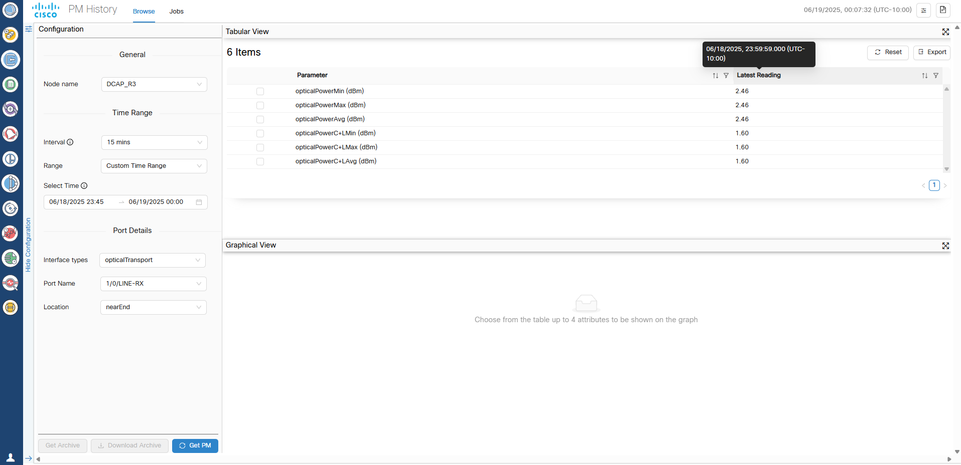
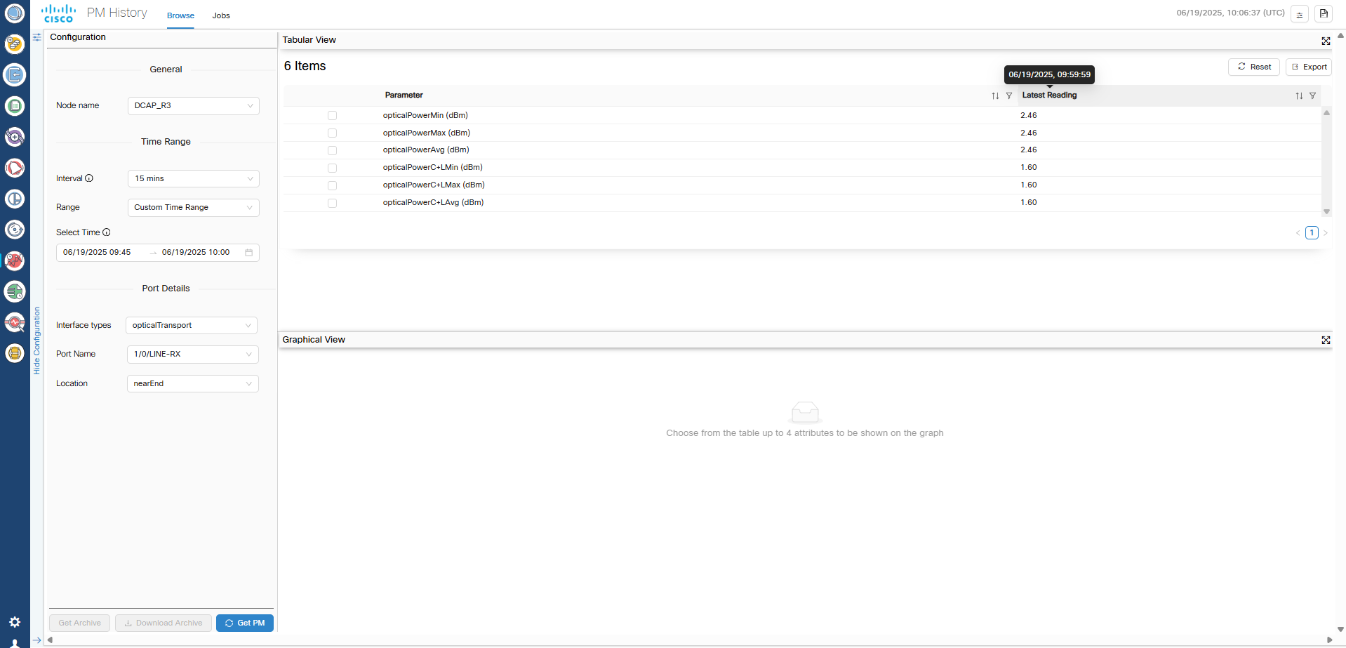
  • Performance monitoring (PM) data loss: The 15-minute and 1-day PM buckets collected during a switchover or failover event are lost.

    PM data collection resumes normally with the next bucket after the switchover or failover alarm clears.

  • SWIM job failures: Any SWIMU ad hoc device configuration backup jobs that are running during a switchover or failover transition to the Failed state.

    Recreate the job to trigger the backup again. Scheduled SWIM jobs that are in progress also fail, but future scheduled executions continue according to the configured schedule.

  • Data corruption during restore operations: Cisco Optical Network Controller supports database restore operations only on the active node.

    If a switchover or failover occurs while a restore operation is in progress, database corruption can occur. In this case, controller services might not return to the ready state.

    Perform the restore operation again to recover the cluster.

  • Switchover and failover duration: Before triggering a manual switchover, verify that all microservices on both active and standby nodes are in the ready state by running the sedo system status command.

    A switchover or failover requires approximately 4 minutes to complete. Do not initiate another switchover during this period.

    After a node failover, the failed node requires approximately 15 to 20 minutes to become ready for a subsequent switchover or failover. Triggering another event before the node is ready can result in a double failure.

    When TAPI is enabled, switchover time can exceed 4 minutes depending on the number of devices and circuits.

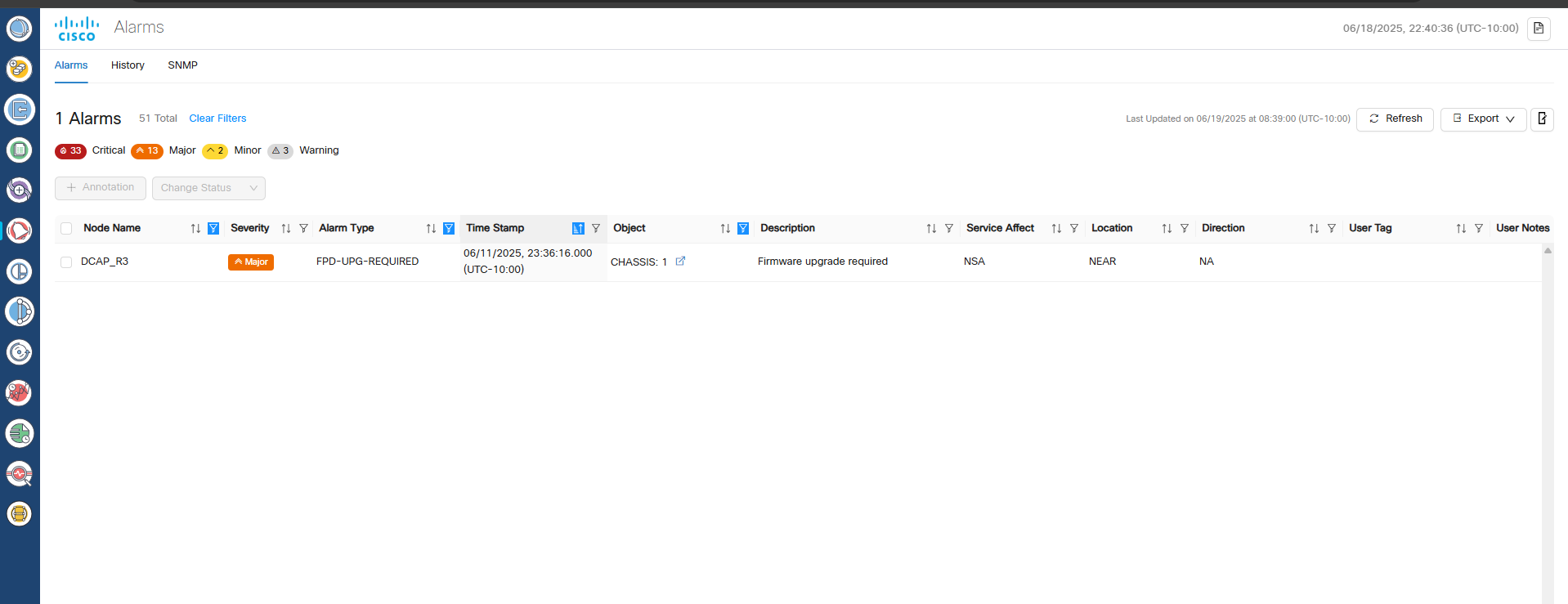
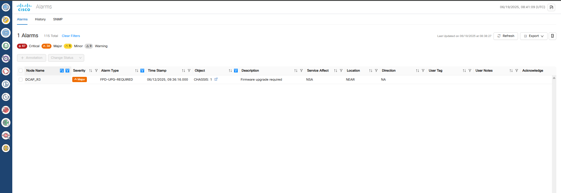
  • Web UI unavailability during failover: During a failover event, the Cisco Optical Network Controller web UI is unavailable until the failover process completes.

    This unavailability typically lasts approximately 4 minutes. After the failover completes, refresh the browser to regain access. To confirm a failover, review the switchover alarm in the Alarm History.

  • Incomplete circuit configurations: If a circuit is partially provisioned and a switchover or failover occurs before database replication completes, the system can create incomplete or disconnected configurations.

    Manually clean up these configurations using Cisco Optical Site Manager.

Install and deploy geo-redundant Cisco Optical Network Controller

Deploy the Cisco Optical Network Controller OVA for each supercluster node. Deploy a separate OVA for every node in vCenter.

For background and deployment considerations, see Geo-redundant deployment overview.

Use the same template values across all nodes and adjust only node-specific settings. Assign consistent names and configure network mappings for every node.

Before you begin

Review prerequisites in Geo-redundant deployment prerequisites.

Follow these steps to deploy the OVA for each supercluster node.

Procedure


Step 1

Right-click the ESXi host in the vSphere client screen and click Deploy OVF Template.

Step 2

In the Select an OVF template screen, choose the URL button to download and install the OVF package from the Internet.

Alternatively, select the Local file radio button to upload the OVA files from your local system, then click Next.
Figure 2. Select an OVF Template

Step 3

In the Select a name and folder screen, specify a unique name for the virtual machine instance. Select the VM location and click Next.

Note


Choose the data center and location for each virtual machine based on your deployment requirements. Compute resources in the subsequent step will appear according to your selection.

Figure 3. Select a name and folder
Figure 4. Select a name and folder
screenshot

Step 4

In the Select a compute resource screen, select the destination for the VM. In the Review details screen, verify the template details and click Next.

Figure 5. Select a Compute Resource
screenshot

Note


The compatibility check proceeds until it completes successfully.

Figure 6. Review Details
screenshot

Step 5

In the Select storage screen, select the virtual disk format according to your requirements. VM Storage Policy is set as Datastore Default and click Next. Select the virtual disk format as Thin Provision.

Figure 7. Select Storage
screenshot

Step 6

In the Select networks screen, select the Control Plane, Eastbound, and Northbound networks you created for each VM and click Next.

Figure 8. Select Networks
screenshot

Step 7

In the Customize template screen, set the values using the following table as a guideline.

Figure 9. Customize Template
screenshot
screenshot
screenshot

For the arbitrator node, choose arbitrator as the Supercluster Cluster Role.

Table 2. Customize Template
Key Values

General

Instance Hostname <instance-name>

Must be a valid DNS name per RFC1123.1.2.4.

  • Contain at most 63 characters.

  • Contain only lowercase alphanumeric characters or '-'

  • Start with an alphanumeric character.

  • End with an alphanumeric character.

SSH Public Key

<ssh-public-key>. Used for SSH access that allows you to connect to the instances securely without the need to manage credentials for multiple instances. SSH public key must be a ed25519 key. See SSH Key Generation.

Node Config

Node Name

Use the same name as Instance Hostname

Initiator Node Select the check box
Supercluster Cluster Index

Set to 1 (active cluster), 2 (standby cluster), or 3 (arbitrator).

Supercluster Cluster Name

Set to cluster1 (active cluster), cluster2 (standby cluster), or cluster3 (arbitrator).

Data Volume Size (GB)

Configure data volume according to the VM profile.

NTP Pools (comma separated)

(Optional) A comma-separated list of the NTP pools. For example, debian.pool.ntp.org

NTP Servers (comma separated)

A comma-separated list of the NTP servers.

Cluster Join Token

Autogenerated value. Leave as is.

Control Plane Node Count 1
Control Plane IP (ip[/subnet]) <Private IP for the Instance> Control Plane Network
Initiator IP <Same IP as Control Plane> Control Plane Network

Northbound Interface

Protocol Static IP
IP (ip[/subnet]) - if not using DHCP <Public IP for the Instance> Northbound Network
Gateway - if not using DHCP <Gateway IP for the Instance> Northbound Network
DNS DNS Server IP

Eastbound Interface

Protocol Static IP
IP (ip[/subnet]) - if not using DHCP

< IP for the Instance> Eastbound Network

Gateway - if not using DHCP <Gateway IP for the Network> Eastbound Network
DNS DNS Server IP

Initiator Config

Northbound Virtual IP Type L3

Cluster Config

Northbound Virtual IP Virtual IP for the SuperCluster
Supercluster Cluster Role

worker for primary and secondary nodes

arbitrator for arbitrator node

Arbitrator Node Name a unique node name.

Attention

 
  • The arbitrator node name must not the same as any node in the supercluster. This field must not be the same as the node name of the arbitrator node either.

  • The arbitrator node name must be the same across all nodes in the supercluster.

Restriction


Do not configure the Northbound and Eastbound networks in the same subnet or VLAN segment. Use separate subnets and VLAN segments for these networks.

Step 8

In Review the details screen, review all your selections and click Finish. To check or change any properties from the review screen, before clicking Finish, click BACK to return to the Customize template screen.

Figure 10. Ready to Complete
screenshot screenshot

Step 9

Repeat the step 8 three times to create two worker node VMs (active and standby) and one arbitrator node VM.

Attention

 
  • You can create the other nodes at a different data center, host, or vCenter instance as needed. Ensure Eastbound and Northbound network connectivity between the nodes.

  • Upon activation of the VM, it does not respond to ping requests. However, you can log in using SSH if the installation is successful.


The OVA deployment is completed for the supercluster nodes.

What to do next

Set up the supercluster

Connect to supercluster VM using SSH keys

Connect to each supercluster VM using SSH keys for secure access.

Use the PEM key generated during SSH key setup to access each node.

Before you begin

Follow these steps to connect to the supercluster virtual machines.

Procedure


Step 1

Connect to each VM using the PEM key generated during SSH Key Generation.

Step 2

Log in to each VM using the private key.

# ssh -i <private-key_file> nxf@<node_ip>

Note

 
  • If you are prompted for a password, there might be a problem with the key. If your SSH key has a passphrase, the system prompts you for the passphrase. If you are prompted for a password even after entering your SSH key passphrase, your PEM key might be wrong or corrupted.

  • If the command times out, check your network settings and make sure the node is reachable.

  • After the nodes are deployed, check the OVA deployment progress in the Tasks console of vSphere Client. Upon successful deployment, Cisco Optical Network Controller can take about 20 minutes to boot.

  • The default user ID is admin. Set the password using the sedo security user set admin --password command.


You are connected to each supercluster VM.

What to do next

Configure static eastbound routes between supercluster nodes

Configure static eastbound routes between supercluster nodes

Configure static routes to allow eastbound traffic to pass between supercluster nodes. If peer node eastbound IPs are in different subnets, create static routes for eastbound traffic between the nodes.

Before you begin

Connect to supercluster VM using SSH keys

Follow these steps to configure eastbound routes.

Procedure


Step 1

Navigate to the configuration directory.

cd /etc/systemd/network/

Step 2

Identify the network configuration file for the eastbound interface ens256. For example, it may be named 10-cloud-init-ens256.network.

Step 3

Open the configuration file with administrative privileges. Update the [Route] section by adding the static routes using this template.

Note

 
Replace all placeholders with the actual IP addresses and gateway information.
[Match]
Name=ens256

[Network]
DHCP=no
DNS=<dns-server-ip>

[Address]
Address=<cluster1-eastbound-ip>/<subnet-mask>

[Route]
Destination=<eastbound-subnet-of-cluster2>/<subnet-mask>
Gateway=<gateway-ip>

[Route]
Destination=<eastbound-subnet-of-cluster3>/<subnet-mask>
Gateway=<gateway-ip>

Step 4

Save the file. Exit the editor.

Example:

# Example
[Match]
Name=ens256

[Network]
DHCP=no
DNS=10.10.128.236

[Address]
Address=172.10.10.11/24

[Route]
Destination=172.10.20.0/24
Gateway=172.30.10.2

[Route]
Destination=172.10.30.0/24
Gateway=172.30.10.2

Note

 
  • Verify that the Name in the [Match] section mateches the correct network interface.

  • Verify that the DNS and gateway IPs are correctly assigned for your network.

Step 5

Use the ping command to verify connectivity between the nodes.

Step 6

Restart the systemd-networkd service to apply the changes.

Example:

sudo systemctl restart systemd-networkd

Step 7

Verify that the routes are created.

ip route

The eastbound routes are configured. Connectivity has been verified.

Configure BGP for supercluster routing

Configure BGP so the supercluster can advertise the virtual IP route.

Before you begin

  • Obtain the router IP address, autonomous system number, and password from your network administrator before you begin.

  • Confirm that each node can reach the northbound network.

Follow these steps to configure BGP for supercluster routing.

Procedure


Step 1

Initialize BGP on each node.

sedo ha bgp init <current_node_name> <current_node_northbound_ip> <current_node_as> --nexthop <current_node_northbound_ip>

Step 2

Add a BGP router to each node.

sedo ha bgp router add <current_node_name> <bgp_router_ip> <bgp_router_as> <bgp_password> --ttl-min 255

Note


Collect the BGP router IP address, router autonomous system number, and BGP password from your network administrator. The BGP password must match the neighbor configuration on the router.

Example:

sedo ha bgp router add conc2512-2 192.168.125.1 65534 password --ttl-min 255

BGP is initialized, and the router is added to each node.

Join clusters into a supercluster

Join three clusters into a single supercluster.

Before you begin

  • Complete the Border Gateway Protocol (BGP) and eastbound routing configuration before you join clusters.

  • Ensure you can run commands on each cluster node.

Follow these steps to join clusters into a supercluster.

Procedure


Step 1

Use the sedo supercluster status command on each node to retrieve the cluster ID.

Example:

sedo supercluster status
# Sample output
┌────────────────────────────────────────────────────────────┐
│ Supercluster Status            │
├──────────────┬─────────────────────────────────────────────┤
│ Cluster ID   │ vk0uFBSwM1vX4_mC1BAabDxAKXYUTv1KH5dcCDawZw4 │
│ Cluster Name │ cluster1       │
│ Cluster Role │ worker          │
│ Peers        │ <No Peers>      │
│ Initialized  │ No              │
└──────────────┴─────────────────────────────────────────────┘

Note


You need the cluster ID for each node for the next steps.

Step 2

Connect cluster1 to cluster2.

  1. Initiate the connection on cluster1.

    Example:

    # Sample output
    sudo sedo supercluster wait-for -b 172.20.2.89:10443 uUD21AaV4cQ8CzZQf0E0YrGmALi0vHASpZI07YzcsQ
    Listening for join requests on 172.20.2.89:10443...
    Please run the following on peer node:
    $ sudo /usr/bin/sedo supercluster join Lh9Gv3FwSUsx7Gu_7EJoIMe4r5YE6ApyHqOEt83fko https://172.20.2.89:10443/join/g4jKVulJo74ptz82lMvngQ
  2. Run the join command generated by cluster1 on cluster2.

    Example:

    sudo /usr/bin/sedo supercluster join Lh9Gv3FwSUsx7Gu_7EJoIMe4r5YE6ApyHqOEt83fko https://172.20.2.89:10443/join/g4jKVulJo74ptz82lMvngQ

Step 3

Connect cluster1 to cluster3.

  1. Initiate the connection on cluster1.

    sudo sedo supercluster wait-for -b <cluster1_node_eastbound_ip>:10443 <cluster3_node_cluster_id>
  2. Run the join command generated by cluster1 on cluster3.

Step 4

Connect cluster2 to cluster3.

  1. Initiate the connection on cluster2.

    sudo sedo supercluster wait-for -b <cluster2_node_eastbound_ip>:10443 <cluster3_node_cluster_id>
  2. Run the join command generated by cluster2 on cluster3.


Clusters are joined and ready for connectivity validation.

Verify cluster connectivity and start the supercluster

Verify connectivity, start the supercluster, and confirm its operational status.

Before you begin

Ensure that clusters are joined and reachable.

Follow these steps to verify connectivity and start the supercluster.

Procedure


Step 1

Use the sedo supercluster connectivity command to verify connectivity between clusters.

Note


Wait until all connections are successful. Clusters typically establish connectivity within 5 minutes.

Example:

sudo sedo supercluster connectivity

┌────────────────────────────────────────────────────────────────┐
│ Supercluster Connectivity          │
├───────────────────────┬───────────────────────┬──────┬─────────┤
│ FROM                  │ TO                    │ RTT  │ RESULT  │
├───────────────────────┼───────────────────────┼──────┼─────────┤
│ cluster2/controller-0 │ cluster1/controller-0 │ 14ms │ Success │
│ cluster2/controller-0 │ cluster3/controller-0 │ 15ms │ Success │
│ cluster1/controller-0 │ cluster3/controller-0 │ 12ms │ Success │
│ cluster1/controller-0 │ cluster2/controller-0 │ 12ms │ Success │
│ cluster3/controller-0 │ cluster2/controller-0 │ 13ms │ Success │
│ cluster3/controller-0 │ cluster1/controller-0 │ 13ms │ Success │
└───────────────────────┴───────────────────────┴──────┴─────────┘
          

Step 2

Use the sedo supercluster start command to start the supercluster.

Note


The node where you execute this command becomes the active node. The other worker node becomes the standby node.

Example:

sudo sedo supercluster start

Checking Supercluster connectivity...Passed
Initiating Supercluster...Done
          

Step 3

Use the sedo supercluster status to verify the supercluster status.

Example:

This sample output shows the result of the status command on the standby node. When DB replication is streaming and DB Lag is 0 bytes, the geo-redundant deployment is running.

sedo supercluster status
┌──────────────────────────────────────────────────────────────────────────────────────┐
│ Supercluster Status          │
├──────────────────┬───────────────────────────────────────────────────────────────────┤
│ Cluster ID       │ QgQV2uXgP1udqshlIssyTwf3LZzEyRh6I3z5MH8almA                       │
│ Cluster Name     │ cluster1  │
│ Cluster Role     │ worker    │
│ Peers            │ cluster2 (worker, jaWeN9BdXUUTxvofwt6Hukt6OQXIUaqo4NxN6zHYDc)     │
│                  │ cluster3 (arbitrator, SUCrwqQjXToG5GKBwckcg_CtzgHstQigaEM1X0988E) │
│ Mode             │ Running   │
│ Current Active   │ cluster1  │
│ Previous Active  │           │
│ Standby Clusters │ cluster2  │
│ Last Switchover  │           │
│ Last Failover    │           │
│ Last Seen        │ controller-0.cluster2: 2025-03-19 11:16:57.051 +0000 UTC          │
│                  │ controller-0.cluster3: 2025-03-19 11:16:57.047 +0000 UTC          │
│                  │ controller-0.cluster1: 2025-03-19 11:16:57.051 +0000 UTC          │
│ Last Peer Error  │           │
│ Server Error     │           │
│ DB Replication   │ streaming │
│ DB Lag           │ 0 bytes   │
└──────────────────┴───────────────────────────────────────────────────────────────────┘

The supercluster is running and connectivity is confirmed.

Validate supercluster service status and installed version

Validate the service status and confirm the installed version.

Run these checks after the supercluster has started.

Before you begin

Follow these steps to validate services and version.

Procedure


Step 1

Check the status of all pods.

sedo system status
┌───────────────────────────────────────────────────────────────────────────────────┐
│ System Status (Fri, 20 Sep 2024 08:21:27 UTC)         │
├────────┬──────────────────────────────┬───────┬─────────┬──────────┬──────────────┤
│ OWNER  │ NAME                         │ NODE  │ STATUS  │ RESTARTS │ STARTED      │
├────────┼──────────────────────────────┼───────┼─────────┼──────────┼──────────────┤
│ onc    │ monitoring                   │ node1 │ Running │ 0        │ 3 hours ago  │
│ onc    │ onc-alarm-service            │ node1 │ Running │ 0        │ 3 hours ago  │
│ onc    │ onc-apps-ui-service          │ node1 │ Running │ 0        │ 3 hours ago  │
│ onc    │ onc-circuit-service          │ node1 │ Running │ 0        │ 3 hours ago  │
│ onc    │ onc-collector-service        │ node1 │ Running │ 0        │ 3 hours ago  │
│ onc    │ onc-config-service           │ node1 │ Running │ 0        │ 3 hours ago  │
│ onc    │ onc-devicemanager-service    │ node1 │ Running │ 0        │ 3 hours ago  │
│ onc    │ onc-inventory-service        │ node1 │ Running │ 0        │ 3 hours ago  │
│ onc    │ onc-nbi-service              │ node1 │ Running │ 0        │ 3 hours ago  │
│ onc    │ onc-netconfcollector-service │ node1 │ Running │ 0        │ 3 hours ago  │
│ onc    │ onc-osapi-gw-service         │ node1 │ Running │ 0        │ 3 hours ago  │
│ onc    │ onc-pce-service              │ node1 │ Running │ 0        │ 3 hours ago  │
│ onc    │ onc-pm-service               │ node1 │ Running │ 0        │ 3 hours ago  │
│ onc    │ onc-pmcollector-service      │ node1 │ Running │ 0        │ 3 hours ago  │
│ onc    │ onc-topology-service         │ node1 │ Running │ 0        │ 3 hours ago  │
│ onc    │ onc-torch-service            │ node1 │ Running │ 0        │ 3 hours ago  │
│ system │ authenticator                │ node1 │ Running │ 0        │ 12 hours ago │
│ system │ controller                   │ node1 │ Running │ 0        │ 12 hours ago │
│ system │ flannel                      │ node1 │ Running │ 0        │ 12 hours ago │
│ system │ ingress-proxy                │ node1 │ Running │ 0        │ 12 hours ago │
│ system │ kafka                        │ node1 │ Running │ 0        │ 12 hours ago │
│ system │ loki                         │ node1 │ Running │ 0        │ 12 hours ago │
│ system │ metrics                      │ node1 │ Running │ 0        │ 12 hours ago │
│ system │ minio                        │ node1 │ Running │ 0        │ 12 hours ago │
│ system │ postgres                     │ node1 │ Running │ 0        │ 12 hours ago │
│ system │ promtail-cltmk               │ node1 │ Running │ 0        │ 12 hours ago │
│ system │ vip-add                      │ node1 │ Running │ 0        │ 12 hours ago │
└────────┴──────────────────────────────┴───────┴─────────┴──────────┴──────────────┘

Note

 
  • The pod statuses appear in separate terminal sessions for each node.

  • The status of all services must be Running.

Step 2

Check the current version.

sedo version
┌──────────────────────────────────────────────────────────────────────────────────────────┐
│Installer: 24.3.2                │
├──────────────┬──────────────────────────────────────────────────────────┬────────────────┤
│ NODE NAME    │ OS VERSION                   │ KERNEL VERSION │
├──────────────┼──────────────────────────────────────────────────────────┼────────────────┤
│ node1-c1-sa1 │ NxFOS 3.2-555 (93358ad257a6cf1e3da439144e3d2e8343b53008) │ 6.1.0-31-amd64 │
└──────────────┴──────────────────────────────────────────────────────────┴────────────────┘
┌────────────────────────────────────────────────────────────────────────────┬────────────────────────────────────────────────────────────┬──────────────┐
│ IMAGE NAME         │ VERSION                        │ NODES        │
├────────────────────────────────────────────────────────────────────────────┼────────────────────────────────────────────────────────────┼──────────────┤
...
└────────────────────────────────────────────────────────────────────────────┴────────────────────────────────────────────────────────────┴──────────────┘

The service status and version information are confirmed.

Set Up Web UI Access to Cisco Optical Network Controller

Enable web user interface access to Cisco Optical Network Controller.

Before you begin

Ensure you have administrator access to the Cisco Optical Network Controller VM.

Follow these steps to set up web user interface access to Cisco Optical Network Controller.

Procedure


Step 1

Use the sedo security user set admin --password command to set the initial UI password for the admin user.

Example:

sedo security user set admin --password

The password must include at least

  • one uppercase letter,

  • one lowercase letter,

  • one number,

  • one special character,

  • must have a minimum length of eight characters.

Note


The password policy for the system includes both configurable settings and nonconfigurable hard requirements to ensure security.

Step 2

(Optional) Change the password policy settings using the sedo security password-policy set command.

sedo security password-policy set --expiration-days <number> --reuse-limit <number> --min-complexity-score <number>

Parameter

Description

expiration-days

Default password expiration used when creating new users, in days.

Default value: 180

min-complexity-score

The password strength forced for local users can be enabled or disabled and can be set in scores of one to five (weak to strong). The password is checked against several dictionaries and common passwords lists, to ensure its complexity according to the selected score.

Default value: 3

reuse-limit

This specifies how many historical passwords are retained and blocked from reuse when you change your password.

Default value: 12

Step 3

Use the sedo security user list to check the default admin user ID.

Step 4

Use the sedo security user admin set --password to change the default password.

Step 5

Open this URL to access the Cisco Optical Network Controller Web UI.

https://<virtual IP>:8443/

Note


Access the web UI only after all the onc services are running. Use the sedo system status command to verify that all services are running.

Step 6

Log in to Cisco Optical Network Controller with the admin user ID and the password set in step 1.


Perform a switchover in a geo-redundant Cisco Optical Network Controller deployment

Switch active and standby roles in a geo-redundant deployment.

Use this procedure when you need to move the active role to another cluster.

Before you begin

  • Verify that a geo-redundant Cisco Optical Network Controller deployment is configured.

  • Verify that the DB replication is streaming and DB Lag is 0 bytes using the sedo supercluster status command.
    sedo supercluster status
    ┌──────────────────────────────────────────────────────────────────────────────────────┐
    │ Supercluster Status          │
    ├──────────────────┬───────────────────────────────────────────────────────────────────┤
    │ Cluster ID       │ QgQV2uXgP1udqshlIssyTwf3LZzEyRh6I3z5MH8almA                       │
    │ Cluster Name     │ cluster1  │
    │ Cluster Role     │ worker    │
    │ Peers            │ cluster2 (worker, jaWeN9BdXUUTxvofwt6Hukt6OQXIUaqo4NxN6zHYDc)     │
    │                  │ cluster3 (arbitrator, SUCrwqQjXToG5GKBwckcg_CtzgHstQigaEM1X0988E) │
    │ Mode             │ Running   │
    │ Current Active   │ cluster1  │
    │ Previous Active  │           │
    │ Standby Clusters │ cluster2  │
    │ Last Switchover  │           │
    │ Last Failover    │           │
    │ Last Seen        │ controller-0.cluster2: 2025-03-19 11:16:57.051 +0000 UTC          │
    │                  │ controller-0.cluster3: 2025-03-19 11:16:57.047 +0000 UTC          │
    │                  │ controller-0.cluster1: 2025-03-19 11:16:57.051 +0000 UTC          │
    │ Last Peer Error  │           │
    │ Server Error     │           │
    │ DB Replication   │ disconnected │DB Lag           │ 0 bytes   │
    └──────────────────┴───────────────────────────────────────────────────────────────────┘
    

Follow these steps to perform a switchover in a geo-redundant deployment.

Procedure


Step 1

Run the sedo supercluster switchover <target-active-cluster-name> command and confirm when prompted.

Note

 
When you perform a dynamic switchover of the active cluster using the sedo supercluster switchover command, the Cisco Optical Network Controller UI may display an HTTP 500 Internal Server Error for up to four minutes while the system stabilizes again.

Example:

nxf@node:~$ sudo sedo supercluster switchover cluster2
Are you sure you want to initiate supercluster switchover to cluster "cluster2"? [y/n]y
The switchover takes place and WebUI displays a message that says Switchover happened. Please refresh the page., and the WebUI update takes about 20 seconds.

Step 2

Use the sedo supercluster status command to SSH in to the new active node and view the supercluster status.

sedo supercluster status
┌──────────────────────────────────────────────────────────────────────────────────────┐
│ Supercluster Status          │
├──────────────────┬───────────────────────────────────────────────────────────────────┤
│ Cluster ID       │ jaWeN9BdXUUTxvofwt6Hukt6OQXIUaqo4NxN6zHYDc                        │
│ Cluster Name     │ cluster2  │
│ Cluster Role     │ worker    │
│ Peers            │ cluster1 (worker, QgQV2uXgP1udqshlIssyTwf3LZzEyRh6I3z5MH8almA)    │
│                  │ cluster3 (arbitrator, SUCrwqQjXToG5GKBwckcg_CtzgHstQigaEM1X0988E) │
│ Mode             │ Running   │
│ Current Active   │ cluster2  │
│ Previous Active  │ cluster1  │
│ Standby Clusters │ cluster1  │
│ Last Switchover  │ 2025-03-19 11:20:49.705 +0000 UTC     │
│ Last Failover    │           │
│ Last Seen        │ controller-0.cluster1: 2025-03-19 11:24:07.056 +0000 UTC          │
│                  │ controller-0.cluster2: 2025-03-19 11:24:07.058 +0000 UTC          │
│                  │ controller-0.cluster3: 2025-03-19 11:24:07.058 +0000 UTC          │
│ Last Peer Error  │           │
│ Server Error     │           │
│ DB Replication   │ streaming │DB Lag           │ 0 bytes   │
└──────────────────┴───────────────────────────────────────────────────────────────────┘

The DB replication status changes from disconnected to streaming as the switchover process progresses. Database replication is complete when the DB Replication status is streaming and DB Lag is 0 bytes.

Note


A switchover alarm is raised by Cisco Optical Network Controller during the switchover process. The alarm is cleared after the switchover. You can see the alarm details under Alarm History in the alarms app.

Step 3

(Optional) Use the raft API to get the supercluster status.

Example:

nxf@node:~$ kubectl exec -it onc-devicemanager-service-0 -- curl -X GET http://controller.nxf-system.svc.cluster.local/api/v1/raft/status

The API response gives you the information from the sedo supercluster status command.

Restriction

 
  • Do not perform a switchover until the DB replication status is Streaming and DB Lag is 0 bytes after the previous switchover. This typically takes five minutes.

  • If you perform a switchover while a delete operation was in progress, you must repeat the deleted operation on the new active after the switchover. This restriction applies to node and circuit delete operations.

  • If the active cluster goes down for some reason, a failover takes place. During a failover, the web UI becomes unavailable for up to a minute, and the system raises the switchover alarm.


The active role switches to the target cluster and status reflects the change.

Upgrade a standalone or high-availability Cisco Optical Network Controller deployment to a geo-redundant deployment

Upgrade a standalone deployment or a high-availability deployment to a geo-redundant deployment. Cisco Optical Network Controller supports upgrades to version 25.1.2 from previous releases. The required upgrade path depends on your current version.

This table describes the available upgrade path options.

Table 3. Upgrade paths
Current version Upgrade Path to 25.1.2
24.3.2 Upgrade from 24.3.2 to 25.1.2
25.1.1 Upgrade from 25.1.1 to 25.1.2
24.3.1 24.3.1 → 24.3.2 → 25.1.2
24.3.1 → 25.1.1 → 25.1.2

These instructions explain how to upgrade a standalone deployment from Release 25.1.1 to 25.1.2 as well as configuring necessary networks for geo-redundant supercluster communication.


Restriction


  • Cisco Optical Network Controller does not support direct downgrades to older releases.

  • To revert to a previous version, you must first create a database backup using the SWIMU application before upgrading. Then, install the desired older version using its OVA file, and finally, restore the database.

  • Refer to the Backup and Restore Database documentation for detailed instructions.


Before you begin

  • Backup Creation: Verify that a full system backup is created. For details about creating a backup, see Backup and Restore Database or use the sedo backup create full command and export the backup for recovery if needed. Use this backup to revert to the older version if your upgrade fails.

    Example:

    root@conc-1:~# sedo backup  create full 
    Creating backup, this may take a while...
    Done creating backup
    root@conc-1:~# sedo backup  list
    ┌───────────────────────────────┬─────────────────────────────────────────┬─────────────────────────────┬──────┬────────────┬──────────────────┐
    │ NAME                          │ TIME        │ SIZE                        │ TYPE │ HOSTNAME   │ POSTGRES VERSION │
    ├───────────────────────────────┼─────────────────────────────────────────┼─────────────────────────────┼──────┼────────────┼──────────────────┤
    │ base_0000000E000000010000009E │ 2025-03-11 04:11:47.733980894 +0000 UTC │ 87 MB (838 MB Uncompressed) │ full │ postgres-0 │ 150008           │
    └───────────────────────────────┴─────────────────────────────────────────┴─────────────────────────────┴──────┴────────────┴──────────────────┘
    
    root@conc-1:~# cd /data
    root@conc-1:/data# sedo backup download base_0000000E000000010000009E
    Downloading Backup       ...  [.....<#>...............] [63.03MB in 9.200973s]
    Finished downloading backup to "/data/nxf-backup-3.2-1741666307.tar.gz"
    
    root@conc-1:/data# scp /data/nxf-backup-3.0-1736872559.tar.gz <remote location>
    
  • Network Configuration: Before installing Cisco Optical Network Controller, create the required networks.

    • Control Plane network: The control plane network helps in the internal communication between the deployed VMs within a cluster.

    • VM network or Northbound network: The VM network is used for communication between the user and the cluster. It handles all the traffic to and from the VMs running on your ESXi hosts.

      This network is your public network through which the UI is hosted. Cisco Optical Network Controller uses this network to connect to Cisco Optical Site Manager devices using Netconf/gRPC.

    • Eastbound network: The Eastbound network helps in the internal communication between the deployed VMs within a supercluster. The active and standby nodes use this network to synchronize their databases. The Postgres database is replicated across both active and standby nodes. MinIO is also replicated on the arbitrator.


      Note


      Bandwidth requirement: The Eastbound network should provide 1 Gbps (1,000 Mbps) bandwidth and maintain latency below 100 ms (milliseconds).

      You can configure the Eastbound network to be a flat Layer 2 network or an L2VPN, where the Eastbound IP addresses of all nodes are in the same subnet. If your Eastbound IPs are in different subnets, you must configure static routing between your nodes for the eastbound network.


  • BGP Router Configuration: Obtain the BGP router IP, Router autonomous system number, and BGP password from network administrators for configuration.

  • VMware Setup: Ensure that the vCenter has the required networks configured and attached correctly. Verify that physical adapters are correctly mapped for Northbound and Eastbound networks.

  • Access and Permissions: Ensure you have the necessary permissions to execute commands and modify network settings on the nodes.

For more details about creating networks, see Installation Requirements.

Follow these steps to upload the system pack for a standalone or high-availability deployment.

Procedure


Step 1

Perform any of these tasks based on the standalone or Geo HA setup.

  • For standalone deployment, log in to the standalone node using the private key.
  • For Geo-redundant deployment, log in to the active node using the private key.

Example:

ssh -i <private-key_file> nxf@<node_ip>

Step 2

Download or copy the 25.1.2 system pack system-pack-file.tar.gz to the NxF SA system running 25.1.1 and place it in the /tmp directory using curl or scp.

Example:

scp user@remote_server:/path/to/system-pack-file.tar.gz /tmp/
curl -o /tmp/system-pack-file.tar.gz http://example.com/path/to/system-pack-file.tar.gz

Step 3

Check the system pack status using the sedo system upgrade list command.

Example:

sedo system upgrade list

Step 4

Follow these steps to upload system pack for standalone or HA deployment.

For standalone

For HA

Upload the system pack using the sedo system upgrade upload command.

sedo system upgrade upload /tmp/system-pack-file.tar.gz
  1. Upload the system pack using the sedo system upgrade upload command.

    sedo system upgrade upload /tmp/system-pack-file.tar.gz
  2. Check the system pack status using the sedo system upgrade pull command.

    sedo system upgrade pull /tmp/system-pack-file.tar.gz

Step 5

Apply the system pack using the sedo system upgrade apply command.

Example:

sedo system upgrade apply /tmp/system-pack-file.tar.gz
The upgrade process takes approximately 30 minutes to complete.

Step 6

Reboot the system using the reboot command.

Example:

reboot

Step 7

After the system reboots, verify the NxF version and system status by using the sedo version and sedo system status commands.

Example:

sedo version
┌──────────────────────────────────────────────────────────────────────────────────────────┐
│ Installer: 24.3.2                │
├──────────────┬──────────────────────────────────────────────────────────┬────────────────┤
│ NODE NAME    │ OS VERSION                   │ KERNEL VERSION │
├──────────────┼──────────────────────────────────────────────────────────┼────────────────┤
│ node1-c1-sc2 │ NxFOS 3.2-555 (93358ad257a6cf1e3da439144e3d2e8343b53008) │ 6.1.0-31-amd64 │
└──────────────┴──────────────────────────────────────────────────────────┴────────────────┘
┌────────────────────────────────────────────────────────────────────────────┬───────────────────────────────────────────────────┬──────────────┐
│ IMAGE NAME         │ VERSION               │ NODES        │
├────────────────────────────────────────────────────────────────────────────┼───────────────────────────────────────────────────┼──────────────┤
│ docker.io/rancher/local-path-provisioner       │ v0.0.30               │ node1-c1-sc2 │
│ dockerhub.cisco.com/cisco-onc-docker/dev/monitoring                        │ dev_latest            │ node1-c1-sc2 │
│ quay.io/coreos/etcd│ v3.5.15               │ node1-c1-sc2 │
│ registry.nxf-system.svc:8443/cisco-onc-docker/dev/alarmservice             │ 24.3.2-5              │ node1-c1-sc2 │
│ registry.nxf-system.svc:8443/cisco-onc-docker/dev/circuit-service          │ 24.3.2-5              │ node1-c1-sc2 │
│ registry.nxf-system.svc:8443/cisco-onc-docker/dev/collector-service        │ 24.3.2-5              │ node1-c1-sc2 │
│ registry.nxf-system.svc:8443/cisco-onc-docker/dev/config-service           │ 24.3.2-5              │ node1-c1-sc2 │
│ registry.nxf-system.svc:8443/cisco-onc-docker/dev/devicemanager-service    │ 24.3.2-5              │ node1-c1-sc2 │
│ registry.nxf-system.svc:8443/cisco-onc-docker/dev/inventory-service        │ 24.3.2-5              │ node1-c1-sc2 │
│ registry.nxf-system.svc:8443/cisco-onc-docker/dev/monitoring               │ 24.3.2-5              │ node1-c1-sc2 │
│ registry.nxf-system.svc:8443/cisco-onc-docker/dev/nbi-service              │ 24.3.2-5              │ node1-c1-sc2 │
│ registry.nxf-system.svc:8443/cisco-onc-docker/dev/netconfcollector-service │ 24.3.2-5              │ node1-c1-sc2 │
│ registry.nxf-system.svc:8443/cisco-onc-docker/dev/onc-apps-ui-service      │ 24.3.2-5              │ node1-c1-sc2 │
│ registry.nxf-system.svc:8443/cisco-onc-docker/dev/onc-kafkarecap-service   │ 0.1.PR93-26c53efb0cf6ebc1f0c4a2aa226a0ab3751b9101 │ node1-c1-sc2 │
│ registry.nxf-system.svc:8443/cisco-onc-docker/dev/osapi-gw-service         │ 24.3.2-5              │ node1-c1-sc2 │
│ registry.nxf-system.svc:8443/cisco-onc-docker/dev/pce_service              │ 24.3.2-5              │ node1-c1-sc2 │
│ registry.nxf-system.svc:8443/cisco-onc-docker/dev/pm-service               │ 24.3.2-5              │ node1-c1-sc2 │
│ registry.nxf-system.svc:8443/cisco-onc-docker/dev/pmcollector-service      │ 24.3.2-5              │ node1-c1-sc2 │
│ registry.nxf-system.svc:8443/cisco-onc-docker/dev/topology-service         │ 24.3.2-5              │ node1-c1-sc2 │
│ registry.nxf-system.svc:8443/cisco-onc-docker/dev/torch                    │ 24.3.2-5              │ node1-c1-sc2 │
│ registry.sedona.ciscolabs.com/nxf/authenticator│ 3.2-508               │ node1-c1-sc2 │
│ registry.sedona.ciscolabs.com/nxf/bgp          │ 3.2-505               │ node1-c1-sc2 │
│ registry.sedona.ciscolabs.com/nxf/controller   │ 3.2-533               │ node1-c1-sc2 │
│ registry.sedona.ciscolabs.com/nxf/firewalld    │ 3.2-505               │ node1-c1-sc2 │
│ registry.sedona.ciscolabs.com/nxf/flannel      │ 3.2-505               │ node1-c1-sc2 │
│ registry.sedona.ciscolabs.com/nxf/ingress-proxy│ 3.2-508               │ node1-c1-sc2 │
│ registry.sedona.ciscolabs.com/nxf/kafka        │ 3.2-505               │ node1-c1-sc2 │
│ registry.sedona.ciscolabs.com/nxf/kubernetes   │ 3.2-505               │ node1-c1-sc2 │
│ registry.sedona.ciscolabs.com/nxf/loki         │ 3.2-505               │ node1-c1-sc2 │
│ registry.sedona.ciscolabs.com/nxf/metrics-exporter                         │ 3.2-505               │ node1-c1-sc2 │
│ registry.sedona.ciscolabs.com/nxf/minio        │ 3.2-505               │ node1-c1-sc2 │
│ registry.sedona.ciscolabs.com/nxf/service-proxy│ 3.2-508               │ node1-c1-sc2 │
│ registry.sedona.ciscolabs.com/nxf/timescale    │ 3.2-515               │ node1-c1-sc2 │
│ registry.sedona.ciscolabs.com/nxf/timescale    │ 3.2-514               │ node1-c1-sc2 │
└────────────────────────────────────────────────────────────────────────────┴───────────────────────────────────────────────────┴──────────────┘
sedo system status
┌───────────────────────────────────────────────────────────────────────────────────┐
│ System Status (Fri, 20 Sep 2024 08:21:27 UTC)         │
├────────┬──────────────────────────────┬───────┬─────────┬──────────┬──────────────┤
│ OWNER  │ NAME                         │ NODE  │ STATUS  │ RESTARTS │ STARTED      │
├────────┼──────────────────────────────┼───────┼─────────┼──────────┼──────────────┤
│ onc    │ monitoring                   │ node1 │ Running │ 0        │ 3 hours ago  │
│ onc    │ onc-alarm-service            │ node1 │ Running │ 0        │ 3 hours ago  │
│ onc    │ onc-apps-ui-service          │ node1 │ Running │ 0        │ 3 hours ago  │
│ onc    │ onc-circuit-service          │ node1 │ Running │ 0        │ 3 hours ago  │
│ onc    │ onc-collector-service        │ node1 │ Running │ 0        │ 3 hours ago  │
│ onc    │ onc-config-service           │ node1 │ Running │ 0        │ 3 hours ago  │
│ onc    │ onc-devicemanager-service    │ node1 │ Running │ 0        │ 3 hours ago  │
│ onc    │ onc-inventory-service        │ node1 │ Running │ 0        │ 3 hours ago  │
│ onc    │ onc-nbi-service              │ node1 │ Running │ 0        │ 3 hours ago  │
│ onc    │ onc-netconfcollector-service │ node1 │ Running │ 0        │ 3 hours ago  │
│ onc    │ onc-osapi-gw-service         │ node1 │ Running │ 0        │ 3 hours ago  │
│ onc    │ onc-pce-service              │ node1 │ Running │ 0        │ 3 hours ago  │
│ onc    │ onc-pm-service               │ node1 │ Running │ 0        │ 3 hours ago  │
│ onc    │ onc-pmcollector-service      │ node1 │ Running │ 0        │ 3 hours ago  │
│ onc    │ onc-topology-service         │ node1 │ Running │ 0        │ 3 hours ago  │
│ onc    │ onc-torch-service            │ node1 │ Running │ 0        │ 3 hours ago  │
│ system │ authenticator                │ node1 │ Running │ 0        │ 12 hours ago │
│ system │ controller                   │ node1 │ Running │ 0        │ 12 hours ago │
│ system │ flannel                      │ node1 │ Running │ 0        │ 12 hours ago │
│ system │ ingress-proxy                │ node1 │ Running │ 0        │ 12 hours ago │
│ system │ kafka                        │ node1 │ Running │ 0        │ 12 hours ago │
│ system │ loki                         │ node1 │ Running │ 0        │ 12 hours ago │
│ system │ metrics                      │ node1 │ Running │ 0        │ 12 hours ago │
│ system │ minio                        │ node1 │ Running │ 0        │ 12 hours ago │
│ system │ postgres                     │ node1 │ Running │ 0        │ 12 hours ago │
│ system │ promtail-cltmk               │ node1 │ Running │ 0        │ 12 hours ago │
│ system │ vip-add                      │ node1 │ Running │ 0        │ 12 hours ago │
└────────┴──────────────────────────────┴───────┴─────────┴──────────┴──────────────┘

Step 8

Verify onboarded sites and services by accessing the Cisco Optical Network Controller UI.

Example:

Use a web browser to open https://<virtual ip>:8443/ and access the Cisco Optical Network Controller Web UI.


What to do next

Configure eastbound and northbound networks

Configure eastbound and northbound networks

Update the interface configuration files. Restart the network services. Verify the network settings in vCenter. Set the eastbound interface to ensure correct connectivity.

Prepare the standalone node so it can communicate over the designated eastbound and northbound interfaces.

Before you begin

Ensure you know the required IP addresses and DNS values for eastbound and northbound interfaces.

Follow these steps to set up eastbound and northbound networks.

Procedure


Step 1

Verify the Eastbound (ens256) and Northbound (ens224) interfaces using the ip address command.

Example:

ip address

3: ens224: <BROADCAST,MULTICAST,UP,LOWER_UP> mtu 1500 qdisc mq state UP group default qlen 1000
    link/ether 00:50:56:9c:16:fb brd ff:ff:ff:ff:ff:ff
    altname enp19s0
    inet 192.168.10.11/24 brd 192.168.10.255 scope global ens224
       valid_lft forever preferred_lft forever
    inet 10.64.103.73/32 scope global ens224
       valid_lft forever preferred_lft forever
    inet6 fe80::250:56ff:fe9c:16fb/64 scope link
       valid_lft forever preferred_lft forever
4: ens256: <BROADCAST,MULTICAST,UP,LOWER_UP> mtu 1500 qdisc mq state UP group default qlen 1000
    link/ether 00:50:56:9c:e1:fc brd ff:ff:ff:ff:ff:ff
    altname enp27s0
    inet 172.10.10.11/24 brd 172.10.10.255 scope global ens256
       valid_lft forever preferred_lft forever
    inet6 fe80::250:56ff:fe9c:e1fc/64 scope link
       valid_lft forever preferred_lft forever

Note


This sample output shows only the relevant part of the command output.

Step 2

Update the IP address for the northbound interface (ens224) by modifying the configuration file located at /etc/systemd/network/10-cloud-init-ens224.network.

Example:

[Address]
Address=<northbound-node1-ip-address>/<subnet>

[Match]
Name=ens224

[Network]
DHCP=no
DNS=<northbound-node1-dns>

[Route]
Destination=0.0.0.0/0
Gateway=<northbound-node1-gateway>

Step 3

Update the IP address of the Eastbound interface (ens256) by editing the interface file located at /etc/systemd/network/10-cloud-init-ens256.network.

Example:

[Address]
Address=<eastbound-node1-ip-address>/<subnet>

[Match]
Name=ens256

[Network]
DHCP=no
DNS=<eastbound-node1-dns>

# Optional - when static route is needed for eastbound network
[Route]
Destination=<network address need to be routed>/<subnet>
Gateway=<eastbound network gateway>

Step 4

Restart the network service to apply the changes.

Example:

sudo systemctl restart systemd-networkd

Step 5

Use vCenter to verify and update the northbound and eastbound network settings for the node.

  1. In vCenter, click ACTIONS in the node screen.

    Screenshot
  2. Click Edit Settings in the drop-down list.

  3. Update the northbound and eastbound networks that you created for the supercluster.

    Screenshot

Step 6

Use SSH to access the upgraded node with the new northbound IP address. Set the eastbound interface.

sedo system set-eastbound eastbound-interface

Example:

sedo system set-eastbound ens256

You have configured the eastbound and northbound networks for the standalone node.

What to do next

Bring up a Worker Node and an Arbitrator Node.

Create worker and arbitrator nodes

This task is necessary when setting up georedundancy. It also prepares the nodes for supercluster configuration.

Use this task to create worker and arbitrator nodes as part of a georedundant Cisco Optical Network Controller deployment.

Before you begin

Configure eastbound and northbound networks

Follow these steps to bring up a worker node and an arbitrator node. Create two more Cisco Optical Network Controller nodes for georedundancy.

Procedure


Step 1

Create two more Cisco Optical Network Controller nodes for Georedundancy.

For more details about the instructions, see Install and Deploy Geo Redundant Cisco Optical Network Controller.

Step 2

(Optional) Edit the interface file located /etc/systemd/network/10-cloud-init-ens256.network to create static routes between the nodes for the eastbound network if the eastbound interfaces for the nodes are in different subnets.

Example:


# Optional - when static route is needed for eastbound network
[Route]
Destination=<network address need to be routed>/<subnet>
Gateway=<eastbound network gateway>

Add the configuration section with the required IP addresses to set up static routes.

Step 3

(Optional) Restart the network service to apply the changes using:

Example:

sudo systemctl restart systemd-networkd

The worker and arbitrator nodes are created and prepared for supercluster setup.

What to do next

Set up the supercluster

Update time zone configuration in a geo-redundant deployment

From R25.1.2, you can update the timezone configuration. Previously, only the UTC time zone was supported. You can now configure Cisco Optical Network Controller in your preferred time zone.

For geo-redundant deployments, use the CLI command to update the timezone on each VM. Restart each VM using the steps described in this procedure to ensure a seamless change to the new timezone configuration. If the time zone configuration differs between VMs, a discrepancy can occur during failover or switchover.


Note


Do not make frequent timezone changes, as it requires a reboot of VMs and services, which might cause inconsistencies.


Apply the same time zone on all three VMs. Be sure to review these limitations before making changes.

Before you begin

  • Verify status of every pod is Running by using the kubectl get pods -A | grep onc command. This example shows a sample output where all pods are running.

    root@vm1-cluster1-node1:~# kubectl get pods -A | grep onc
    onc                  monitoring-0        2/2     Running   0              21m 
    onc                  onc-alarm-service-0 2/2     Running   3 (51m ago)    3h6m 
    onc                  onc-apps-ui-service-6f95dfbc7c-60w87ne          2/2     Running   3 (51m ago)    3h6m 
    onc                  onc-circuit-service-0                           2/2     Running   3 (51m ago)    3h6m 
    onc                  onc-collector-service-0                         2/2     Running   3 (51m ago)    3h6m 
    onc                  onc-config-service-02/2     Running   3 (51m ago)    3h6m 
    onc                  onc-devicemanager-service-0                     2/2     Running   3 (51m ago)    3h6m 
    onc                  onc-inventory-service-0                         2/2     Running   3 (51m ago)    3h6m 
    onc                  onc-nbi-service-0   2/2     Running   3 (51m ago)    3h6m 
    onc                  onc-netconfcollector-service-85bd7c89bf-qc8pf   2/2     Running   0              21m
     
  • Verify that any previous switchover or failover has finished. Confirm that data replication across the active and standby nodes is complete. Use the sedo supercluster status to see the supercluster status and confirm that the DB replication status is streaming and DB Lag is 0.

    sedo supercluster status 
    ┌───────────────────────────────────────────────────────────────────────────────────────┐ 
    │ Supercluster Status           │ 
    ├──────────────────┬────────────────────────────────────────────────────────────────────┤ 
    │ Cluster ID       │ QCTdDdt_rlRd9lgzRM15vSeb0r1tkLMkfCK4DoAy1aw                        │ 
    │ Cluster Name     │ cluster1   │ 
    │ Cluster Role     │ worker     │ 
    │ Peers            │ cluster2 (worker, rabSbdhIWtq1qzhW1lZTm0Hu5_tIxOFZgDyWr5pac90)     │ 
    │                  │ cluster3 (arbitrator, XxHjr5wMmDyiYW6jbvaCcGZW8VIasb4sBv8x0B15DYk) │ 
    │ Mode             │ Running    │ 
    │ Current Active   │ cluster1   │ 
    │ Previous Active  │ cluster2   │ 
    │ Standby Clusters │ cluster2   │ 
    │ Last Switchover  │ 2025-06-09 00:34:46.826 -0500 CDT      │ 
    │ Last Failover    │            │ 
    │ Last Seen        │ controller-0.cluster3: 2025-06-09 00:58:23.636 -0500 CDT           │ 
    │                  │ controller-0.cluster2: 2025-06-09 00:58:23.641 -0500 CDT           │ 
    │                  │ controller-0.cluster1: 2025-06-09 00:58:23.641 -0500 CDT           │ 
    │ Last Peer Error  │            │ 
    │ Server Error     │            │ 
    │ DB Replication   │ streaming  │ 
    │ DB Lag           │ 0 bytes    │ 
    └──────────────────┴────────────────────────────────────────────────────────────────────┘ 

Follow these steps to configure time zone configuration in a geo-redundant deployment.

Procedure

SUMMARY STEPS

  1. Use SSH to access the three VMs and run this command.
  2. Reboot the standby cluster using the sudo reboot command.
  3. Verify the standby is up and running using these commands.
  4. Perform a manual switchover using the sedo supercluster switchover cluster command. Wait for the switchover and data replication to complete.
  5. Repeat steps 2 and 3 for the new standby VM and the arbitrator VM.
  6. If you want to make the original VM active, repeat Step 4.

DETAILED STEPS


Step 1

Use SSH to access the three VMs and run this command.

sudo timedatectl set-timezone timezone-name

Example:

In this example, the time zone is set to JST.

root@vm1-cluster1-node1:~# sudo timedatectl set-timezone Asia/Tokyo 

root@vm1-cluster1-node1:~# timedatectl 

               Local time: Mon 2025-06-09 15:01:26 JST 

           Universal time: Mon 2025-06-09 06:01:26 UTC 

                 RTC time: Mon 2025-06-09 06:01:26 

                Time zone: Japan (JST, +0900) 

System clock synchronized: yes 

              NTP service: active 

          RTC in local TZ: no

A few valid time zones are:

Asia/Kolkata
Asia/Dubai
Europe/Amsterdam
Africa/Bujumbura

Step 2

Reboot the standby cluster using the sudo reboot command.

Step 3

Verify the standby is up and running using these commands.

  • kubectl get pods -A | grep onc

  • sedo supercluster status

Verify the time zone in one of the pods using these commands. See the offset after the time.

root@vm1-cluster1-node1:~# kubectl exec -ti onc-torch-service-0 -n onc -- bash 

onc-torch-service-0:/$ date -R 

Mon, 09 Jun 2025 15:22:42 +0900 

Step 4

Perform a manual switchover using the sedo supercluster switchover cluster command. Wait for the switchover and data replication to complete.

Note

 
When you perform a dynamic switchover of the active cluster using the sedo supercluster switchover command, the Cisco Optical Network Controller UI may display an HTTP 500 Internal Server Error for up to four minutes while the system stabilizes again.
root@vm1-cluster1-node1:~# sedo supercluster switchover cluster2 

Are you sure you want to initiate supercluster switchover to cluster "cluster2"? [y/n] y 

Make sure DB replication status is streaming and DB Lag is 0.


root@vm1-cluster1-node1:~# sedo supercluster status 

┌───────────────────────────────────────────────────────────────────────────────────────┐ 
│ Supercluster Status           │ 
├──────────────────┬────────────────────────────────────────────────────────────────────┤ 
│ Cluster ID       │ QCTdDdt_rlRd9lgzRM15vSeb0r1tkLMkfCK4DoAy1aw                        │ 
│ Cluster Name     │ cluster1   │ 
│ Cluster Role     │ worker     │ 
│ Peers            │ cluster2 (worker, rabSbdhIWtq1qzhW1lZTm0Hu5_tIxOFZgDyWr5pac90)     │ 
│                  │ cluster3 (arbitrator, XxHjr5wMmDyiYW6jbvaCcGZW8VIasb4sBv8x0B15DYk) │ 
│ Mode             │ Running    │ 
│ Current Active   │ cluster2   │ 
│ Previous Active  │ cluster1   │ 
│ Standby Clusters │ cluster1   │ 
│ Last Switchover  │ 2025-06-09 15:23:29.686 +0900 JST      │ 
│ Last Failover    │            │ 
│ Last Seen        │ controller-0.cluster3: 2025-06-09 15:23:34.277 +0900 JST           │ 
│                  │ controller-0.cluster2: 2025-06-09 15:23:34.418 +0900 JST           │ 
│                  │ controller-0.cluster1: 2025-06-09 15:23:34.418 +0900 JST           │ 
│ Last Peer Error  │            │ 
│ Server Error     │            │ 
│ DB Replication   │ streaming  │ 
│ DB Lag           │ 0 bytes    │ 
└──────────────────┴────────────────────────────────────────────────────────────────────┘ 

root@vm109-cluster2-node1:~# kubectl get pods -A | grep onc 

onc                  monitoring-0        2/2     Running   0              50m 
onc                  onc-alarm-service-0 2/2     Running   16 (65m ago)   4h23m 
onc                  onc-apps-ui-service-6c474df87d-6aq3bqd          2/2     Running   15 (65m ago)   4h23m 
onc                  onc-circuit-service-0                           2/2     Running   15 (65m ago)   4h23m 
onc                  onc-collector-service-0                         2/2     Running   15 (65m ago)   4h23m 
onc                  onc-config-service-02/2     Running   15 (65m ago)   4h23m 
onc                  onc-devicemanager-service-0                     2/2     Running   17 (65m ago)   4h23m 
onc                  onc-inventory-service-0                         2/2     Running   15 (65m ago)   4h23m 
onc                  onc-nbi-service-0   2/2     Running   15 (65m ago)   4h23m 
onc                  onc-netconfcollector-service-59b855956b-hrbbb   2/2     Running   0              3m18s 
onc                  onc-osapi-gw-service-0                          2/2     Running   15 (65m ago)   4h23m 
onc                  onc-pce-service-0   2/2     Running   15 (65m ago)   4h23m 
onc                  onc-pm-service-0    2/2     Running   13 (65m ago)   3h34m 
onc                  onc-pmcollector-service-785669f8b7-7ndn4        2/2     Running   0              50m 
onc                  onc-topology-service-0                          2/2     Running   15 (65m ago)   4h23m 
onc                  onc-torch-service-0 2/2     Running   16 (65m ago)   4h23m 
 

Step 5

Repeat steps 2 and 3 for the new standby VM and the arbitrator VM.

Step 6

If you want to make the original VM active, repeat Step 4.


Time zone configuration has been updated and Cisco Optical Network Controller web UI now displays time in the newly configured time zone.

This table shows screenshots highlighting the behavioral differences between Releases 25.1.1 and 25.1.2. In Release 25.1.2, the timestamp includes the time zone name and offset.

Release 25.1.2

Release 25.1.1

Figure 11. Alarms
Screenshot
Figure 12. Alarms
Screenshot
Figure 13. PM History
Screenshot
Figure 14. PM History
Screenshot
Figure 15. Nodes
Screenshot
Figure 16. Nodes
Screenshot

This table summarizes how different system components handle time zones and describes related limitations.

Component Time Zone Behavior Notes
Database (Alarms & Logs) Stored in UTC During time zone transitions (for example, switchover), the UI might temporarily show alarms with different time zone stamps until the system converges.
Cross-launch from Cisco Optical Network Controller Offset preserved and IANA name may differ Multiple IANA names can map to the same offset (for example, Asia/Colombo and Asia/Kolkata are both UTC +05:30).
TAPI Data and Notifications UTC (+00:00) Always uses UTC regardless of system time zone.
SNMP Traps Epoch time Time zone offset is not applied to epoch timestamps.
Developer Logs and Techdump UTC No time zone conversion applied.

Revert to a previous version of Cisco Optical Network Controller

This is a manual process. Automatic rollback is not supported. You cannot perform a revert from within Cisco Optical Network Controller.


Restriction


  • Cisco Optical Network Controller does not support direct downgrades to older releases.

  • To revert to a previous version, you must first create a database backup using the SWIMU application before upgrading. Then, install the desired older version using its OVA file, and finally, restore the database.

  • Refer to the Backup and Restore Database documentation for detailed instructions.


You can revert Cisco Optical Network Controller to a previous version by reinstalling the software and restoring the database from a backup.

Before you begin

Create a backup of the Cisco Optical Network Controller database. For details on creating a database backup, see Backup and Restore Database.

Follow these steps to revert to a previous version of Cisco Optical Network Controller.

Procedure

SUMMARY STEPS

  1. For stand-alone deployments:
  2. For georedundant deployments:

DETAILED STEPS


Step 1

For stand-alone deployments:

  1. Reinstall the previous version of Cisco Optical Network Controller, which is the version used for the backup. See Install Cisco Optical Network Controller Using VMware vSphere.

  2. Follow the procedure to perform database restore from a backup. See Backup and Restore Database.

Step 2

For georedundant deployments:

  1. Reinstall the previous version of Cisco Optical Network Controller, which is the version used for the backup. See Install and Deploy Geo Redundant Cisco Optical Network Controller.

  2. Follow the procedure to perform database restore from a backup. See Backup and Restore Database.