- About this Guide
- Chapter 1, Install the Shelf and Backplane Cable
- Chapter 2, Install Cards and Fiber-Optic Cable
- Chapter 3, Connect the PC and Log Into the GUI
- Chapter 4, Turn Up Node
- Chapter 5, Turn Up Network
- Chapter 6, Create Circuits and VT Tunnels
- Chapter 7, Manage Alarms
- Chapter 8, Monitor Performance
- Chapter 9, Manage Circuits
- Chapter 10, Change Node Settings
- Chapter 11, Change Card Settings
- Chapter 12, Upgrade Cards and Spans
- Chapter 13, Upgrade Network Configurations
- Chapter 14, Add and Remove Nodes
- Chapter 15, Maintain the Node
- Chapter 16, Power Down the ONS 15454
- Appendix A, CTC Information and Shortcuts
- Appendix B, Shelf Assembly Specifications
- Appendix C, Network Element Defaults
- Glossary
Install Cards and Fiber-Optic Cable

Note ![]() The terms "Unidirectional Path Switched Ring" and "UPSR" may appear in Cisco literature. These terms do not refer to using Cisco ONS 15xxx products in a unidirectional path switched ring configuration. Rather, these terms, as well as "Path Protected Mesh Network" and "PPMN," refer generally to Cisco's path protection feature, which may be used in any topological network configuration. Cisco does not recommend using its path protection feature in any particular topological network configuration.
The terms "Unidirectional Path Switched Ring" and "UPSR" may appear in Cisco literature. These terms do not refer to using Cisco ONS 15xxx products in a unidirectional path switched ring configuration. Rather, these terms, as well as "Path Protected Mesh Network" and "PPMN," refer generally to Cisco's path protection feature, which may be used in any topological network configuration. Cisco does not recommend using its path protection feature in any particular topological network configuration.
This chapter explains how to install the Cisco ONS 15454 cards and fiber-optic cable (fiber).
Before You Begin
This section lists the chapter procedures (NTPs). Turn to a procedure for applicable tasks (DLPs).
1. ![]() 15 Install the Common Control Cards—Complete this procedure before installing any other cards.
15 Install the Common Control Cards—Complete this procedure before installing any other cards.
2. ![]() 16 Install the Optical Cards—Complete this procedure as needed.
16 Install the Optical Cards—Complete this procedure as needed.
3. ![]() 17 Install the Electrical Cards—Complete this procedure as needed.
17 Install the Electrical Cards—Complete this procedure as needed.
4. ![]() 18 Install the Ethernet Cards—Complete this procedure as needed.
18 Install the Ethernet Cards—Complete this procedure as needed.
5. ![]() 116 Remove and Replace a Card—Complete this procedure as needed to remove and replace a card, including deleting the card from Cisco Transport Controller (CTC) and changing an optical card without losing the card's provisioning.
116 Remove and Replace a Card—Complete this procedure as needed to remove and replace a card, including deleting the card from Cisco Transport Controller (CTC) and changing an optical card without losing the card's provisioning.
6. ![]() 115 Preprovision a Slot—Complete this procedure as needed to provision an empty card slot with a card that will be installed later.
115 Preprovision a Slot—Complete this procedure as needed to provision an empty card slot with a card that will be installed later.
7. ![]() 19 Install the Fiber-Optic Cables—Complete this procedure to install fiber on the optical cards or Ethernet Gigabit Interface Converters (GBICs) and to route the fiber through the bottom of the shelf.
19 Install the Fiber-Optic Cables—Complete this procedure to install fiber on the optical cards or Ethernet Gigabit Interface Converters (GBICs) and to route the fiber through the bottom of the shelf.
8. ![]() 20 Replace the Front Door—If the front door was removed, complete this procedure to replace the front door and ground strap after installing cards and fiber.
20 Replace the Front Door—If the front door was removed, complete this procedure to replace the front door and ground strap after installing cards and fiber.

Warning ![]() Only trained and qualified personnel should be allowed to install, replace, or service this equipment.
Only trained and qualified personnel should be allowed to install, replace, or service this equipment.

NTP-A15 Install the Common Control Cards
Purpose |
This procedure describes how to install the common control cards. |
Tools/Equipment |
TCC+/TCC2 cards XC/XCVT/XC10G (cross-connect) cards AIC/AIC-I card |
Prerequisite Procedures |
NTP-A13 Perform the Shelf Installation Acceptance Test, page 1-60 |
Required/As Needed |
Required |
Onsite/Remote |
Onsite |
Security Level |
Provisioning or higher |
Warning ![]() During this procedure, wear grounding wrist straps to avoid ESD damage to the card. Do not directly touch the backplane with your hand or any metal tool due to electrical hazard.
During this procedure, wear grounding wrist straps to avoid ESD damage to the card. Do not directly touch the backplane with your hand or any metal tool due to electrical hazard.
Note ![]() If you install a card incorrectly, the FAIL LED flashes continuously.
If you install a card incorrectly, the FAIL LED flashes continuously.
Step 1 ![]() If you plan to install XC/XCVT cards, review Table 2-1 to determine card/slot compatibility. If you plan to install XC10G cards, review Table 2-2 to determine card/slot compatibility.
If you plan to install XC/XCVT cards, review Table 2-1 to determine card/slot compatibility. If you plan to install XC10G cards, review Table 2-2 to determine card/slot compatibility.
Step 2 ![]() Complete the "DLP-A36 Install the TCC+/TCC2 Cards" task.
Complete the "DLP-A36 Install the TCC+/TCC2 Cards" task.
Step 3 ![]() Complete the "DLP-A37 Install the XC, XCVT, or XC10G Cards" task.
Complete the "DLP-A37 Install the XC, XCVT, or XC10G Cards" task.
Step 4 ![]() Complete the "DLP-A38 Install the Alarm Interface Controller or Alarm Interface Controller-International Card" task, if necessary.
Complete the "DLP-A38 Install the Alarm Interface Controller or Alarm Interface Controller-International Card" task, if necessary.
Step 5 ![]() If you discover that you installed the wrong card in a slot, see the "116 Remove and Replace a Card" procedure.
If you discover that you installed the wrong card in a slot, see the "116 Remove and Replace a Card" procedure.
Step 6 ![]() Proceed to the "16 Install the Optical Cards" procedure, the "17 Install the Electrical Cards" procedure, or the "18 Install the Ethernet Cards" procedure, as applicable for your site.
Proceed to the "16 Install the Optical Cards" procedure, the "17 Install the Electrical Cards" procedure, or the "18 Install the Ethernet Cards" procedure, as applicable for your site.
Note ![]() X indicates that a card is supported in the slot.
X indicates that a card is supported in the slot.
|
|
|
|
|
|
|
|
|
|
|
|
|
|
|
|
|
|
|
|---|---|---|---|---|---|---|---|---|---|---|---|---|---|---|---|---|---|
|
|
|
|
|
|
|
|
|
|
|
|
|
|
|
|
|
|
|
TCC+/TCC2 |
X |
X |
|||||||||||||||
XC/XCVT |
X |
X |
|||||||||||||||
AIC |
X |
||||||||||||||||
AIC-I |
X |
||||||||||||||||
DS1-14 |
X |
X |
X |
X |
X |
X |
X |
X |
X |
X |
X |
X |
|||||
DS1N-14 |
X3 |
X3 |
X |
X3 |
X3 |
X3 |
X3 |
X3 |
X3 |
X |
X3 |
X3 |
|||||
DS3-12 |
X |
X |
X |
X |
X |
X |
X |
X |
X |
X |
X |
X |
|||||
DS3-12E |
X |
X |
X |
X |
X |
X |
X |
X |
X |
X |
X |
X |
|||||
DS3N-12 |
X3 |
X3 |
X |
X3 |
X3* |
X3 |
X3 |
X3 |
X3 |
X |
X3 |
X3 |
|||||
DS3N-12E |
X3 |
X3 |
X |
X3 |
X3 |
X3 |
X3 |
X3 |
X3 |
X |
X3 |
X3 |
|||||
DS3XM-6 |
X |
X |
X |
X |
X |
X |
X |
X |
X |
X |
X |
X |
|||||
EC1-12 |
X |
X |
X |
X |
X |
X |
X |
X |
X |
X |
X |
X |
|||||
E100T-12 |
X |
X |
X |
X |
X |
X |
X |
X |
X |
X |
X |
X |
|||||
E1000-2 |
X |
X |
X |
X |
X |
X |
X |
X |
X |
X |
X |
X |
|||||
E100T-G |
X |
X |
X |
X |
X |
X |
X |
X |
X |
X |
X |
X |
|||||
E1000-2-G |
X |
X |
X |
X |
X |
X |
X |
X |
X |
X |
X |
X |
|||||
G1000-4 |
Not supported with XC/XCVT cards. Requires XC10G cards. |
||||||||||||||||
G1K-4 |
X |
X |
X |
X |
|||||||||||||
ML100-12 |
X |
X |
X |
X |
|||||||||||||
ML1000-2 |
X |
X |
X |
X |
|||||||||||||
OC3 IR 4/STM1 SH 1310 |
X |
X |
X |
X |
X |
X |
X |
X |
X |
X |
X |
X |
|||||
OC3IR/STM1SH 1310-8 |
Not supported with XC/XCVT cards. Requires XC10G cards. |
||||||||||||||||
OC12 IR STM4 SH 1310 |
X |
X |
X |
X |
X |
X |
X |
X |
X |
X |
X |
X |
|||||
OC12 LR/STM4 LH 1310 |
X |
X |
X |
X |
X |
X |
X |
X |
X |
X |
X |
X |
|||||
OC12 IR/STM4 SH 1310-4 |
Not supported with XC/XCVT cards. Requires XC10G cards. |
||||||||||||||||
OC12 LR/STM4 LH 1550 |
X |
X |
X |
X |
X |
X |
X |
X |
X |
X |
X |
X |
|||||
OC48 IR 1310 |
X |
X |
X |
X |
|||||||||||||
OC48 LR 1550 |
X |
X |
X |
X |
|||||||||||||
OC48 IR/STM16 SH AS 1310 |
X |
X |
X |
X |
|||||||||||||
OC48 LR/STM16 LH AS 1550 |
X |
X |
X |
X |
|||||||||||||
OC48-ELR/STM16 EH 100 GHz |
X |
X |
X |
X |
|||||||||||||
OC48 ELR 200 GHz |
X |
X |
X |
X |
|||||||||||||
OC192 SR/STM64 IO 1310 |
Not supported with XC/XCVT cards. Requires XC10G cards. |
||||||||||||||||
OC192 IR/STM64 SH 1550 |
Not supported with XC/XCVT cards. Requires XC10G cards. |
||||||||||||||||
OC192 LR/STM64 LH 1550 |
Not supported with XC/XCVT cards. Requires XC10G cards. |
||||||||||||||||
OC192 LR/STM64 LH ITU 15xx.xx |
Not supported with XC/XCVT cards. Requires XC10G cards. |
||||||||||||||||
TXP_MR_10G |
X |
X |
X |
X |
X |
X |
X |
X |
X |
X |
X |
X |
|||||
MXP_2.5G_10G |
X |
X |
X |
X |
X |
X |
X |
X |
X |
X |
X |
X |
|||||
1 MS identifies slots 1 to 4 and 14 to 17 ("multispeed" slot). 2 HS identifies slots 5, 6, 12, and 13 ("high-speed" slot). 3 This identifies 1:N cards that operate as normal DS1 or DS3 cards when installed in certain slots. |
Note ![]() X indicates that a card is supported in the slot.
X indicates that a card is supported in the slot.
Note ![]() The XC10G card requires the ANSI shelf with high-speed fans.
The XC10G card requires the ANSI shelf with high-speed fans.
|
|
|
|
|
|
|
|
|
|
|
|
|
|
|
|
|
|
|
|---|---|---|---|---|---|---|---|---|---|---|---|---|---|---|---|---|---|
|
|
|
|
|
|
|
|
|
|
|
|
|
|
|
|
|
|
|
TCC+/TCC2 |
X |
X |
|||||||||||||||
XC10G |
X |
X |
|||||||||||||||
AIC |
X |
||||||||||||||||
AIC-I |
X |
||||||||||||||||
DS1-14 |
X |
X |
X |
X |
X |
X |
X |
X |
X |
X |
X |
X |
|||||
DS1N-14 |
X3 |
X3 |
X |
X3 |
X3 |
X3 |
X3 |
X3 |
X3 |
X |
X3 |
X3 |
|||||
DS3-12 |
X |
X |
X |
X |
X |
X |
X |
X |
X |
X |
X |
X |
|||||
DS3-12E |
X |
X |
X |
X |
X |
X |
X |
X |
X |
X |
X |
X |
|||||
DS3N-12 |
X3 |
X3 |
X |
X3 |
X3 |
X3 |
X3 |
X3 |
X3 |
X |
X3 |
X3 |
|||||
DS3N-12E |
X3 |
X3 |
X |
X3 |
X3 |
X3 |
X3 |
X3 |
X3 |
X |
X3 |
X3 |
|||||
DS3XM-6 |
X |
X |
X |
X |
X |
X |
X |
X |
X |
X |
X |
X |
|||||
EC1-12 |
X |
X |
X |
X |
X |
X |
X |
X |
X |
X |
X |
X |
|||||
E100T-12 |
Not supported with the XC10G card. |
||||||||||||||||
E1000-2 |
Not supported with the XC10G card. |
||||||||||||||||
E100T-G |
X |
X |
X |
X |
X |
X |
X |
X |
X |
X |
X |
X |
|||||
E1000-2-G |
X |
X |
X |
X |
X |
X |
X |
X |
X |
X |
X |
X |
|||||
G1000-4 |
X |
X |
X |
X |
X |
X |
X |
X |
X |
X |
X |
X |
|||||
G1K-4 |
X |
X |
X |
X |
X |
X |
X |
X |
X |
X |
X |
X |
|||||
ML100-12 |
X |
X |
X |
X |
X |
X |
X |
X |
X |
X |
X |
X |
|||||
ML1000-2 |
X |
X |
X |
X |
X |
X |
X |
X |
X |
X |
X |
X |
|||||
OC3 IR 4/STM1 SH 1310 |
X |
X |
X |
X |
X |
X |
X |
X |
X |
X |
X |
X |
|||||
OC3IR/STM1SH 1310-8 |
X |
X |
X |
X |
X |
X |
X |
X |
|||||||||
OC12 IR STM4 SH 1310 |
X |
X |
X |
X |
X |
X |
X |
X |
X |
X |
X |
X |
|||||
OC12 LR/STM4 LH 1310 |
X |
X |
X |
X |
X |
X |
X |
X |
X |
X |
X |
X |
|||||
OC12 IR/STM4 SH 1310-4 |
X |
X |
X |
X |
X |
X |
X |
X |
|||||||||
OC12 LR/STM4 LH 1550 |
X |
X |
X |
X |
X |
X |
X |
X |
X |
X |
X |
X |
|||||
OC48 IR 1310 |
X |
X |
X |
X |
|||||||||||||
OC48 LR 1550 |
X |
X |
X |
X |
|||||||||||||
OC48 IR/STM16 SH AS 1310 |
X |
X |
X |
X |
X |
X |
X |
X |
X |
X |
X |
X |
|||||
OC48 LR/STM16 LH AS 1550 |
X |
X |
X |
X |
X |
X |
X |
X |
X |
X |
X |
X |
|||||
OC48-ELR/STM16 EH 100 GHz |
X |
X |
X |
X |
|||||||||||||
OC48 ELR 200 GHz |
X |
X |
X |
X |
|||||||||||||
OC192 SR/STM64 IO 1310 |
X |
X |
X |
X |
|||||||||||||
OC192 IR/STM64 SH 1550 |
X |
X |
X |
X |
|||||||||||||
OC192 LR/STM64 LH 1550 |
X |
X |
X |
X |
|||||||||||||
OC192 LR/STM64 LH ITU 15xx.xx |
X |
X |
X |
X |
|||||||||||||
TXP_MR_10G |
X |
X |
X |
X |
X |
X |
X |
X |
X |
X |
X |
X |
|||||
MXP_2.5G_10G |
X |
X |
X |
X |
X |
X |
X |
X |
X |
X |
X |
X |
|||||
1 MS identifies slots 1 to 4 and 14 to 17 ("multispeed" slot). 2 HS identifies slots 5, 6, 12, and 13 ("high-speed" slot). 3 This identifies 1:N cards that operate as normal DS1 or DS3 cards when installed in certain slots. |
Step 7 ![]() If you are installing optical cards, continue with the "16 Install the Optical Cards" procedure.
If you are installing optical cards, continue with the "16 Install the Optical Cards" procedure.
Stop. You have completed this procedure.
DLP-A36 Install the TCC+/TCC2 Cards
Note ![]() When installing cards, let each card completely boot before installing the next card.
When installing cards, let each card completely boot before installing the next card.
Step 1 ![]() Open the latches/ejectors of the first TCC+/TCC2 card that you will install.
Open the latches/ejectors of the first TCC+/TCC2 card that you will install.
Step 2 ![]() Use the latches/ejectors to firmly slide the card along the guide rails until the card plugs into the receptacle at the back of the slot (Slot 7 or 11).
Use the latches/ejectors to firmly slide the card along the guide rails until the card plugs into the receptacle at the back of the slot (Slot 7 or 11).
Step 3 ![]() Verify that the card is inserted correctly and close the latches/ejectors on the card.
Verify that the card is inserted correctly and close the latches/ejectors on the card.
Note ![]() It is possible to close the latches/ejectors when the card is not completely plugged into the backplane. Ensure that you cannot insert the card any further.
It is possible to close the latches/ejectors when the card is not completely plugged into the backplane. Ensure that you cannot insert the card any further.
If you insert a card into a slot provisioned for a different card, all LEDS turn off.
Step 4 ![]() If you are using the TCC2, proceed to Step 5. If you are using the TCC+, verify the LED activity:
If you are using the TCC2, proceed to Step 5. If you are using the TCC+, verify the LED activity:
•![]() The red FAIL LED turns on and remains illuminated for 20 to 30 seconds.
The red FAIL LED turns on and remains illuminated for 20 to 30 seconds.
•![]() The red FAIL LED blinks for 35 to 45 seconds.
The red FAIL LED blinks for 35 to 45 seconds.
•![]() The red FAIL LED remains illuminated for 5 to 10 seconds.
The red FAIL LED remains illuminated for 5 to 10 seconds.
•![]() All LEDs (including the CRIT, MAJ, MIN, REM, SYNC, and ACO LEDs) blink once and turn off for 5 to 10 seconds.
All LEDs (including the CRIT, MAJ, MIN, REM, SYNC, and ACO LEDs) blink once and turn off for 5 to 10 seconds.
•![]() The ACT/STBY LED turns on. (The ACT/STBY LED might take several minutes to illuminate while the data communication channel (DCC) processor boots.)
The ACT/STBY LED turns on. (The ACT/STBY LED might take several minutes to illuminate while the data communication channel (DCC) processor boots.)
•![]() Proceed to Step 6.
Proceed to Step 6.
Step 5 ![]() Verify the LED activity of the TCC2:
Verify the LED activity of the TCC2:
•![]() All LEDs turn on briefly.
All LEDs turn on briefly.
•![]() The red FAIL LED, the yellow ACT/STBY LED, the red REM LED, the green SYNC LED, and the green ACO LED turn on and remain illuminated for about 10 seconds.
The red FAIL LED, the yellow ACT/STBY LED, the red REM LED, the green SYNC LED, and the green ACO LED turn on and remain illuminated for about 10 seconds.
•![]() The red FAIL LED and the green ACT/STBY LED turn on and remain illuminated for about 40 seconds.
The red FAIL LED and the green ACT/STBY LED turn on and remain illuminated for about 40 seconds.
•![]() The red FAIL LED blinks for about 10 seconds.
The red FAIL LED blinks for about 10 seconds.
•![]() The red FAIL LED remains illuminated for about 5 seconds.
The red FAIL LED remains illuminated for about 5 seconds.
•![]() All LEDs (including the CRIT, MAJ, MIN, REM, SYNC, and ACO LEDs) blink once and turn off for about 10 seconds.
All LEDs (including the CRIT, MAJ, MIN, REM, SYNC, and ACO LEDs) blink once and turn off for about 10 seconds.
•![]() The ACT/STBY LED turns on. (The ACT/STBY LED might take several minutes to illuminate while the DCC processor boots.)
The ACT/STBY LED turns on. (The ACT/STBY LED might take several minutes to illuminate while the DCC processor boots.)
Note ![]() If the FAIL LED is illuminated continuously on the TCC+/TCC2 card, see the tip below about the TCC+/TCC2 automatic upload.
If the FAIL LED is illuminated continuously on the TCC+/TCC2 card, see the tip below about the TCC+/TCC2 automatic upload.
Note ![]() Alarm LEDs might be illuminated; disregard alarm LEDs until you are logged into CTC and can view the Alarms tab.
Alarm LEDs might be illuminated; disregard alarm LEDs until you are logged into CTC and can view the Alarms tab.

Tip ![]() When a newly installed TCC+/TCC2 card has a different version of the ONS 15454 software installed than the version running on the active TCC+/TCC2, the newly installed TCC+/TCC2 card automatically copies the software version running on the active TCC+/TCC2. You do not need to do anything in this situation. However, the loading TCC+/TCC2 card does not boot up in the normal manner. When the card is first inserted, the red FAIL LED stays on for a short period. The FAIL LED then blinks normally and all LEDs go dark. The FAIL LED and the ACT/STBY LED flash alternately every 30 to 45 seconds as the new software loads onto the new TCC+/TCC2 card. After loading the new software for approximately 30 minutes, the TCC+/TCC2 card becomes the standby card and the amber LED is illuminated.
When a newly installed TCC+/TCC2 card has a different version of the ONS 15454 software installed than the version running on the active TCC+/TCC2, the newly installed TCC+/TCC2 card automatically copies the software version running on the active TCC+/TCC2. You do not need to do anything in this situation. However, the loading TCC+/TCC2 card does not boot up in the normal manner. When the card is first inserted, the red FAIL LED stays on for a short period. The FAIL LED then blinks normally and all LEDs go dark. The FAIL LED and the ACT/STBY LED flash alternately every 30 to 45 seconds as the new software loads onto the new TCC+/TCC2 card. After loading the new software for approximately 30 minutes, the TCC+/TCC2 card becomes the standby card and the amber LED is illuminated.
Step 6 ![]() Verify that the ACT/STBY LED is green for active. The IP address for the node, the temperature of the ONS 15454, and the time of day should be displayed on the LCD. The default time and date is 12:00 AM, January 1, 1970.
Verify that the ACT/STBY LED is green for active. The IP address for the node, the temperature of the ONS 15454, and the time of day should be displayed on the LCD. The default time and date is 12:00 AM, January 1, 1970.
Step 7 ![]() The LCD cycles through the IP address, node name, and software version. Verify that the correct software version displays on the LCD.
The LCD cycles through the IP address, node name, and software version. Verify that the correct software version displays on the LCD.
Step 8 ![]() If the LCD shows the correct software version, continue with Step 9. If the LCD does not show the correct software version, upgrade the software or remove the TCC+/TCC2 card and install a replacement card.
If the LCD shows the correct software version, continue with Step 9. If the LCD does not show the correct software version, upgrade the software or remove the TCC+/TCC2 card and install a replacement card.
Refer to the Cisco ONS 15454 Software Upgrade Guide or the "NTP-A163 Restore the Node to Factory Configuration" procedure on page 15-12 to replace the software. To swap the TCC+/TCC2, see the "116 Remove and Replace a Card" procedure.
Step 9 ![]() Open the latches/ejectors of the redundant TCC+/TCC2 card.
Open the latches/ejectors of the redundant TCC+/TCC2 card.
Step 10 ![]() Use the latches/ejectors to firmly slide the card along the guide rails until the card plugs into the receptacle at the back of the slot (Slot 7 or 11).
Use the latches/ejectors to firmly slide the card along the guide rails until the card plugs into the receptacle at the back of the slot (Slot 7 or 11).
Step 11 ![]() Verify that the card is inserted correctly and close the latches/ejectors on the card.
Verify that the card is inserted correctly and close the latches/ejectors on the card.
Note ![]() It is possible to close the latches/ejectors when the card is not completely plugged into the backplane. Ensure that you cannot insert the card any further.
It is possible to close the latches/ejectors when the card is not completely plugged into the backplane. Ensure that you cannot insert the card any further.
Step 12 ![]() If you are using the TCC2, proceed to Step 13. If you are using the TCC+, verify the LED activity:
If you are using the TCC2, proceed to Step 13. If you are using the TCC+, verify the LED activity:
•![]() The red FAIL LED turns on and remains illuminated for 20 to 30 seconds.
The red FAIL LED turns on and remains illuminated for 20 to 30 seconds.
•![]() The red FAIL LED blinks for 35 to 45 seconds.
The red FAIL LED blinks for 35 to 45 seconds.
•![]() The red FAIL LED remains illuminated for 5 to 10 seconds.
The red FAIL LED remains illuminated for 5 to 10 seconds.
•![]() All LEDs (including the CRIT, MAJ, MIN, REM, SYNC, and ACO LEDs) blink once and turn off for 5 to 10 seconds.
All LEDs (including the CRIT, MAJ, MIN, REM, SYNC, and ACO LEDs) blink once and turn off for 5 to 10 seconds.
•![]() The ACT/STBY LED turns on. (The ACT/STBY LED might take several minutes to illuminate while the DCC processor boots.)
The ACT/STBY LED turns on. (The ACT/STBY LED might take several minutes to illuminate while the DCC processor boots.)
•![]() Proceed to Step 14.
Proceed to Step 14.
Step 13 ![]() Verify the LED activity of the TCC2:
Verify the LED activity of the TCC2:
•![]() All LEDs turn on for a short moment.
All LEDs turn on for a short moment.
•![]() The red FAIL LED, the yellow ACT/STBY LED, the red REM LED, the green SYNC LED, and the green ACO LED turn on and remain illuminated for about 10 seconds.
The red FAIL LED, the yellow ACT/STBY LED, the red REM LED, the green SYNC LED, and the green ACO LED turn on and remain illuminated for about 10 seconds.
•![]() The red FAIL LED and the green ACT/STBY LED turn on and remain illuminated for about 40 seconds.
The red FAIL LED and the green ACT/STBY LED turn on and remain illuminated for about 40 seconds.
•![]() The red FAIL LED blinks for about 10 seconds.
The red FAIL LED blinks for about 10 seconds.
•![]() The red FAIL LED remains illuminated for about 5 seconds.
The red FAIL LED remains illuminated for about 5 seconds.
•![]() All LEDs (including the CRIT, MAJ, MIN, REM, SYNC, and ACO LEDs) blink once and turn off for about 10 seconds.
All LEDs (including the CRIT, MAJ, MIN, REM, SYNC, and ACO LEDs) blink once and turn off for about 10 seconds.
•![]() The ACT/STBY LED turns on. (The ACT/STBY LED might take several minutes to illuminate while the DCC processor boots.)
The ACT/STBY LED turns on. (The ACT/STBY LED might take several minutes to illuminate while the DCC processor boots.)
Note ![]() If the FAIL LED is illuminated continuously on the TCC+/TCC2 card, see the tip in Step 4 about the TCC+/TCC2 automatic upload.
If the FAIL LED is illuminated continuously on the TCC+/TCC2 card, see the tip in Step 4 about the TCC+/TCC2 automatic upload.
Note ![]() If you insert a card into a slot provisioned for a different card, all LEDS turn off.
If you insert a card into a slot provisioned for a different card, all LEDS turn off.
Note ![]() Alarm LEDs might be illuminated; disregard alarm LEDs until you are logged into CTC and can view the Alarms tab.
Alarm LEDs might be illuminated; disregard alarm LEDs until you are logged into CTC and can view the Alarms tab.
Step 14 ![]() Verify that the ACT/STBY LED is amber for standby.
Verify that the ACT/STBY LED is amber for standby.
Step 15 ![]() Return to your originating procedure (NTP).
Return to your originating procedure (NTP).
DLP-A37 Install the XC, XCVT, or XC10G Cards
Note ![]() This is not the procedure to use when upgrading from XC to XCVT cards or from XCVT to XC10G cards. If you are performing an XC to XCVT upgrade or an XCVT to a XC10G upgrade, see Chapter 12, "Upgrade Cards and Spans."
This is not the procedure to use when upgrading from XC to XCVT cards or from XCVT to XC10G cards. If you are performing an XC to XCVT upgrade or an XCVT to a XC10G upgrade, see Chapter 12, "Upgrade Cards and Spans."
Note ![]() When installing cards, let each card completely boot before installing the next card.
When installing cards, let each card completely boot before installing the next card.
Step 1 ![]() Open the latches/ejectors of the first XC, XCVT, or XC10G card that you will install.
Open the latches/ejectors of the first XC, XCVT, or XC10G card that you will install.
Step 2 ![]() Open the card latches/ejectors.
Open the card latches/ejectors.
Step 3 ![]() Use the latches/ejectors to firmly slide the card along the guide rails until the card plugs into the receptacle at the back of the slot (Slot 8 or 10).
Use the latches/ejectors to firmly slide the card along the guide rails until the card plugs into the receptacle at the back of the slot (Slot 8 or 10).
Step 4 ![]() Verify that the card is inserted correctly and close the latches/ejectors on the card.
Verify that the card is inserted correctly and close the latches/ejectors on the card.
Note ![]() It is possible to close the latches/ejectors when the card is not completely plugged into the backplane. Ensure that you cannot insert the card any further.
It is possible to close the latches/ejectors when the card is not completely plugged into the backplane. Ensure that you cannot insert the card any further.
Step 5 ![]() Verify the LED activity:
Verify the LED activity:
•![]() The red LED turns on and remains illuminated for 20 to 30 seconds.
The red LED turns on and remains illuminated for 20 to 30 seconds.
•![]() The red LED blinks for 35 to 45 seconds.
The red LED blinks for 35 to 45 seconds.
•![]() The red LED remains illuminated for 5 to 10 seconds.
The red LED remains illuminated for 5 to 10 seconds.
•![]() All LEDs blink once and turn on.
All LEDs blink once and turn on.
•![]() The ACT/STBY LED turns on.
The ACT/STBY LED turns on.
Note ![]() If you insert a card into a slot provisioned for a different card, all LEDS turn off.
If you insert a card into a slot provisioned for a different card, all LEDS turn off.
Note ![]() If the red FAIL LED does not illuminate, check the power.
If the red FAIL LED does not illuminate, check the power.
Note ![]() If the red FAIL LED is illuminated continuously or the LEDs act erratically, the card is not installed properly. Remove the card and repeat Steps 1 to 5.
If the red FAIL LED is illuminated continuously or the LEDs act erratically, the card is not installed properly. Remove the card and repeat Steps 1 to 5.
Step 6 ![]() Verify that the ACT/STBY LED is green for active.
Verify that the ACT/STBY LED is green for active.
Step 7 ![]() Use the latches/ejectors to firmly slide the second cross-connect card along the guide rails until the card plugs into the receptacle at the back of the slot (Slot 8 or 10).
Use the latches/ejectors to firmly slide the second cross-connect card along the guide rails until the card plugs into the receptacle at the back of the slot (Slot 8 or 10).
Step 8 ![]() Verify that the card is inserted correctly and close the latches/ejectors on the card.
Verify that the card is inserted correctly and close the latches/ejectors on the card.
Note ![]() It is possible to close the latches/ejectors when the card is not completely plugged into the backplane. Ensure that you cannot insert the card any further.
It is possible to close the latches/ejectors when the card is not completely plugged into the backplane. Ensure that you cannot insert the card any further.
Step 9 ![]() Verify the LED activity:
Verify the LED activity:
•![]() The red LED turns on and remains illuminated for 20 to 30 seconds.
The red LED turns on and remains illuminated for 20 to 30 seconds.
•![]() The red LED blinks for 35 to 45 seconds.
The red LED blinks for 35 to 45 seconds.
•![]() The red LED remains illuminated for 5 to 10 seconds.
The red LED remains illuminated for 5 to 10 seconds.
•![]() All LEDs blink once and turn on.
All LEDs blink once and turn on.
•![]() The ACT/STBY LED turns on.
The ACT/STBY LED turns on.
Note ![]() If you insert a card into a slot provisioned for a different card, all LEDS turn off.
If you insert a card into a slot provisioned for a different card, all LEDS turn off.
Note ![]() If the red FAIL LED does not illuminate, check the power.
If the red FAIL LED does not illuminate, check the power.
Note ![]() If the red FAIL LED is illuminated continuously or the LEDs act erratically, the card is not installed properly. Remove the card and repeat Steps 7 to 9.
If the red FAIL LED is illuminated continuously or the LEDs act erratically, the card is not installed properly. Remove the card and repeat Steps 7 to 9.
Step 10 ![]() Verify that the ACT/STBY LED is amber for standby.
Verify that the ACT/STBY LED is amber for standby.
Step 11 ![]() Return to your originating procedure (NTP).
Return to your originating procedure (NTP).
DLP-A38 Install the Alarm Interface Controller or Alarm Interface Controller-International Card
Purpose |
This task installs the AIC or AIC-I card. |
Tools/Equipment |
AIC or AIC-I card |
Prerequisite Procedures |
36 Install the TCC+/TCC2 Cards |
Required/As Needed |
Required to use the ENVIR ALARMS (external alarms and controls) or orderwire functions. The AIC-I card can be used in both the ANSI and ETSI markets, while the AIC card is only used for the ANSI market. |
Onsite/Remote |
Onsite |
Security Level |
None |
Note ![]() When installing cards, let each card completely boot before installing the next card.
When installing cards, let each card completely boot before installing the next card.
Step 1 ![]() Open the latches/ejectors on the card.
Open the latches/ejectors on the card.
Step 2 ![]() Open the card latches/ejectors.
Open the card latches/ejectors.
Step 3 ![]() Use the latches/ejectors to firmly slide the card along the guide rails until the card plugs into the receptacle at the back of the slot (Slot 9).
Use the latches/ejectors to firmly slide the card along the guide rails until the card plugs into the receptacle at the back of the slot (Slot 9).
Step 4 ![]() Verify that the card is inserted correctly and close the latches/ejectors on the card.
Verify that the card is inserted correctly and close the latches/ejectors on the card.
Note ![]() It is possible to close the latches/ejectors when the card is not completely plugged into the backplane. Ensure that you cannot insert the card any further.
It is possible to close the latches/ejectors when the card is not completely plugged into the backplane. Ensure that you cannot insert the card any further.
Step 5 ![]() If you have installed the AIC card, verify the following:
If you have installed the AIC card, verify the following:
•![]() The red FAIL LED remains illuminated for 1 second, then blinks for 1 to 5 seconds.
The red FAIL LED remains illuminated for 1 second, then blinks for 1 to 5 seconds.
•![]() After 1 to 5 seconds, all LEDs blink once and turn off.
After 1 to 5 seconds, all LEDs blink once and turn off.
•![]() The ACT LED turns on.
The ACT LED turns on.
Step 6 ![]() If you have installed the AIC-I card, verify the following:
If you have installed the AIC-I card, verify the following:
•![]() The red FAIL LED remains illuminated for 1 second, then blinks for 1 to 5 seconds.
The red FAIL LED remains illuminated for 1 second, then blinks for 1 to 5 seconds.
•![]() The PWR A and PWR B LEDs illuminate red and the two INPUT/OUTPUT LEDs illuminate green for approximately 3 seconds.
The PWR A and PWR B LEDs illuminate red and the two INPUT/OUTPUT LEDs illuminate green for approximately 3 seconds.
•![]() The PWR A LED turns green, the INPUT/OUTPUT LEDs turn off, and the ACT LED illuminates.
The PWR A LED turns green, the INPUT/OUTPUT LEDs turn off, and the ACT LED illuminates.
Note ![]() If the red FAIL LED does not illuminate, check the power.
If the red FAIL LED does not illuminate, check the power.
Note ![]() Before you insert a card into a slot provisioned for a different card, complete the "DLP-A191 Delete a Card" task for the previously provisioned card.
Before you insert a card into a slot provisioned for a different card, complete the "DLP-A191 Delete a Card" task for the previously provisioned card.
Note ![]() If you do insert a card into a slot provisioned for a different card, no LEDs turn on.
If you do insert a card into a slot provisioned for a different card, no LEDs turn on.
Note ![]() If the red FAIL LED is illuminated continuously or the LEDs act erratically, the card is not installed properly. Remove the card and repeat Steps 1 to 5.
If the red FAIL LED is illuminated continuously or the LEDs act erratically, the card is not installed properly. Remove the card and repeat Steps 1 to 5.
Step 7 ![]() Return to your originating procedure (NTP).
Return to your originating procedure (NTP).
NTP-A16 Install the Optical Cards
Warning ![]() During this procedure, wear grounding wrist straps to avoid ESD damage to the card. Do not directly touch the backplane with your hand or any metal tool due to electrical hazard.
During this procedure, wear grounding wrist straps to avoid ESD damage to the card. Do not directly touch the backplane with your hand or any metal tool due to electrical hazard.
Warning ![]() Class I (21 CFR 1040.10 and 1040.11) and Class 1M (IEC 60825-1 2001-01) laser products.
Class I (21 CFR 1040.10 and 1040.11) and Class 1M (IEC 60825-1 2001-01) laser products.
Warning ![]() Invisible laser radiation may be emitted from the end of the unterminated fiber cable or connector. Do not stare into the beam or view directly with optical instruments. Viewing the laser output with certain optical instruments (for example, eye loupes, magnifiers, and microscopes) within a distance of 100 mm may pose an eye hazard. Use of controls or adjustments or performance of procedures other than those specified may result in hazardous radiation exposure.
Invisible laser radiation may be emitted from the end of the unterminated fiber cable or connector. Do not stare into the beam or view directly with optical instruments. Viewing the laser output with certain optical instruments (for example, eye loupes, magnifiers, and microscopes) within a distance of 100 mm may pose an eye hazard. Use of controls or adjustments or performance of procedures other than those specified may result in hazardous radiation exposure.
Warning ![]() On all optical cards except the OC192 LR/STM64 LH 1550 card, the laser is on even when the optical port is not in service. On the OC192 LR/STM64 LH 1550 card, the laser is active when the card is booted and the safety key is in the on position (labeled 1). The laser is off when the safety key is off (labeled 0).
On all optical cards except the OC192 LR/STM64 LH 1550 card, the laser is on even when the optical port is not in service. On the OC192 LR/STM64 LH 1550 card, the laser is active when the card is booted and the safety key is in the on position (labeled 1). The laser is off when the safety key is off (labeled 0).
Note ![]() To simplify path protection to bidirectional line switch ring (BLSR) conversion and node addition, equip optical cards according to a high-speed east (Slots 12 and 13) and west (Slots 5 and 6) configuration. This configuration is not mandatory.
To simplify path protection to bidirectional line switch ring (BLSR) conversion and node addition, equip optical cards according to a high-speed east (Slots 12 and 13) and west (Slots 5 and 6) configuration. This configuration is not mandatory.
Note ![]() If you install a card incorrectly, the FAIL LED flashes continuously.
If you install a card incorrectly, the FAIL LED flashes continuously.
Step 1 ![]() If you installed XC or XCVT cards, review Table 2-1 to determine card/slot compatibility. If you installed XC10G cards, review Table 2-2 to determine card/slot compatibility.
If you installed XC or XCVT cards, review Table 2-1 to determine card/slot compatibility. If you installed XC10G cards, review Table 2-2 to determine card/slot compatibility.
Install higher-capacity cards first; for example, install an OC-192 card before installing an OC-48 card. Let each card completely boot before installing the next card.
Step 2 ![]() Open the card latches/ejectors.
Open the card latches/ejectors.
Warning ![]() Before installing an OC192 LR/STM64 LH 1550 card, make sure the safety key on the faceplate is in off position (labeled 0). When in the on position (labeled 1), the laser is activated.
Before installing an OC192 LR/STM64 LH 1550 card, make sure the safety key on the faceplate is in off position (labeled 0). When in the on position (labeled 1), the laser is activated.
Step 3 ![]() Use the latches/ejectors to firmly slide the optical card along the guide rails until the card plugs into the receptacle at the back of the slot.
Use the latches/ejectors to firmly slide the optical card along the guide rails until the card plugs into the receptacle at the back of the slot.
Step 4 ![]() Verify that the card is inserted correctly and close the latches/ejectors on the card.
Verify that the card is inserted correctly and close the latches/ejectors on the card.
Note ![]() It is possible to close the latches/ejectors when the card is not completely plugged into the backplane. Ensure that you cannot insert the card any further.
It is possible to close the latches/ejectors when the card is not completely plugged into the backplane. Ensure that you cannot insert the card any further.
Step 5 ![]() Verify the LED activity:
Verify the LED activity:
•![]() The red FAIL LED turns on and remains illuminated for 20 to 30 seconds.
The red FAIL LED turns on and remains illuminated for 20 to 30 seconds.
•![]() The red FAIL LED blinks for 35 to 45 seconds.
The red FAIL LED blinks for 35 to 45 seconds.
•![]() All LEDs blink once and turn off for 5 to 10 seconds.
All LEDs blink once and turn off for 5 to 10 seconds.
•![]() The ACT or ACT/STBY LED turns on. The signal fail (SF) LED can persist until all card ports connect to their far end counterparts and a signal is present.
The ACT or ACT/STBY LED turns on. The signal fail (SF) LED can persist until all card ports connect to their far end counterparts and a signal is present.
Step 6 ![]() If the card does not boot up properly, or the LED activity does not mirror Step 5, check the following:
If the card does not boot up properly, or the LED activity does not mirror Step 5, check the following:
•![]() When a physical card type does not match the type of card provisioned for that slot in CTC, the card might not boot. If an optical card does not boot, open CTC and ensure that the slot is not provisioned for a different card type before assuming the card is faulty.
When a physical card type does not match the type of card provisioned for that slot in CTC, the card might not boot. If an optical card does not boot, open CTC and ensure that the slot is not provisioned for a different card type before assuming the card is faulty.
•![]() If the red FAIL LED does not illuminate, check the power.
If the red FAIL LED does not illuminate, check the power.
•![]() If you insert a card into a slot provisioned for a different card, all LEDS turn off.
If you insert a card into a slot provisioned for a different card, all LEDS turn off.
•![]() If the red FAIL LED is illuminated continuously or the LEDs behave erratically, the card is not installed properly. Remove the card and repeat Steps 2 to 5.
If the red FAIL LED is illuminated continuously or the LEDs behave erratically, the card is not installed properly. Remove the card and repeat Steps 2 to 5.
Step 7 ![]() Complete the "19 Install the Fiber-Optic Cables" procedure.
Complete the "19 Install the Fiber-Optic Cables" procedure.
Step 8 ![]() If you discover that you installed the wrong card in a slot, complete the "116 Remove and Replace a Card" procedure.
If you discover that you installed the wrong card in a slot, complete the "116 Remove and Replace a Card" procedure.
Step 9 ![]() Continue with the "17 Install the Electrical Cards" procedure.
Continue with the "17 Install the Electrical Cards" procedure.
Stop. You have completed this procedure.
NTP-A17 Install the Electrical Cards
Purpose |
This procedure describes how to install the electrical cards (DS-1, DS-3, and EC1). |
Tools/Equipment |
Electrical cards |
Prerequisite Procedures |
15 Install the Common Control Cards 16 Install the Optical Cards (if applicable) |
Required/As Needed |
As needed |
Onsite/Remote |
Onsite |
Security Level |
Provisioning or higher |
Warning ![]() During this procedure, wear grounding wrist straps to avoid ESD damage to the card. Do not directly touch the backplane with your hand or any metal tool due to electrical hazard.
During this procedure, wear grounding wrist straps to avoid ESD damage to the card. Do not directly touch the backplane with your hand or any metal tool due to electrical hazard.
Note ![]() Install higher-capacity cards first; for example, install a DS-3 card before installing a DS-1 card. Let each card completely boot before installing the next card.
Install higher-capacity cards first; for example, install a DS-3 card before installing a DS-1 card. Let each card completely boot before installing the next card.
Step 1 ![]() If you installed XC or XCVT cards, review Table 2-1 to determine card/slot compatibility. If you installed XC10G cards, review Table 2-2 to determine card/slot compatibility.
If you installed XC or XCVT cards, review Table 2-1 to determine card/slot compatibility. If you installed XC10G cards, review Table 2-2 to determine card/slot compatibility.
Step 2 ![]() Open the card latches/ejectors.
Open the card latches/ejectors.
Step 3 ![]() Use the latches/ejectors to firmly slide the card along the guide rails until the card plugs into the receptacle at the back of the slot.
Use the latches/ejectors to firmly slide the card along the guide rails until the card plugs into the receptacle at the back of the slot.
Step 4 ![]() Verify that the card is inserted correctly and close the latches/ejectors on the card.
Verify that the card is inserted correctly and close the latches/ejectors on the card.
Note ![]() It is possible to close the latches/ejectors when the card is not completely plugged into the backplane. Ensure that you cannot insert the card any further.
It is possible to close the latches/ejectors when the card is not completely plugged into the backplane. Ensure that you cannot insert the card any further.
Step 5 ![]() Verify the LED activity:
Verify the LED activity:
•![]() The red FAIL LED turns on and remains illuminated for 10 to 15 seconds.
The red FAIL LED turns on and remains illuminated for 10 to 15 seconds.
•![]() If the red FAIL LED does not illuminate, check the power.
If the red FAIL LED does not illuminate, check the power.
•![]() The red FAIL LED blinks for 30 to 40 seconds.
The red FAIL LED blinks for 30 to 40 seconds.
•![]() All LEDs blink once and turn off for 1 to 5 seconds.
All LEDs blink once and turn off for 1 to 5 seconds.
•![]() The ACT or ACT/STBY LED turns on. The SF LED can persist until all card ports connect to their far end counterparts and a signal is present.
The ACT or ACT/STBY LED turns on. The SF LED can persist until all card ports connect to their far end counterparts and a signal is present.
Note ![]() If you insert a card into a slot provisioned for a different card, all LEDs turn off.
If you insert a card into a slot provisioned for a different card, all LEDs turn off.
Note ![]() If the red FAIL LED is illuminated continuously or the LEDs behave erratically, the card is not installed properly. Remove the card and repeat Steps 2 to 5.
If the red FAIL LED is illuminated continuously or the LEDs behave erratically, the card is not installed properly. Remove the card and repeat Steps 2 to 5.
Step 6 ![]() If you discover that you installed the wrong card in a slot, complete the "116 Remove and Replace a Card" procedure.
If you discover that you installed the wrong card in a slot, complete the "116 Remove and Replace a Card" procedure.
Stop. You have completed this procedure.
NTP-A18 Install the Ethernet Cards
Purpose |
This procedure describes how to install the Ethernet cards. |
Tools/Equipment |
Ethernet cards |
Prerequisite Procedures |
15 Install the Common Control Cards 16 Install the Optical Cards (if applicable) 17 Install the Electrical Cards (if applicable) |
Required/As Needed |
As needed |
Onsite/Remote |
Onsite |
Security Level |
None |
Warning ![]() During this procedure, wear grounding wrist straps to avoid ESD damage to the card. Do not directly touch the backplane with your hand or any metal tool due to electrical hazard.
During this procedure, wear grounding wrist straps to avoid ESD damage to the card. Do not directly touch the backplane with your hand or any metal tool due to electrical hazard.
Warning ![]() Class I (21 CFR 1040.10 and 1040.11) and Class 1M (IEC 60825-1 2001-01) laser products.
Class I (21 CFR 1040.10 and 1040.11) and Class 1M (IEC 60825-1 2001-01) laser products.
Warning ![]() Invisible laser radiation may be emitted from the end of the unterminated fiber cable or connector. Do not stare into the beam or view directly with optical instruments. Viewing the laser output with certain optical instruments (for example, eye loupes, magnifiers, and microscopes) within a distance of 100 mm may pose an eye hazard. Use of controls or adjustments or performance of procedures other than those specified may result in hazardous radiation exposure.
Invisible laser radiation may be emitted from the end of the unterminated fiber cable or connector. Do not stare into the beam or view directly with optical instruments. Viewing the laser output with certain optical instruments (for example, eye loupes, magnifiers, and microscopes) within a distance of 100 mm may pose an eye hazard. Use of controls or adjustments or performance of procedures other than those specified may result in hazardous radiation exposure.
Step 1 ![]() If you installed XC or XCVT cards review Table 2-1 to determine card/slot compatibility. If you installed XC10G cards, review Table 2-2 to determine card/slot compatibility.
If you installed XC or XCVT cards review Table 2-1 to determine card/slot compatibility. If you installed XC10G cards, review Table 2-2 to determine card/slot compatibility.
Step 2 ![]() Complete the "DLP-A39 Install Ethernet Cards" task. Allow each card to boot completely before installing the next card.
Complete the "DLP-A39 Install Ethernet Cards" task. Allow each card to boot completely before installing the next card.
Note ![]() If you discover that you installed the wrong card in a slot, complete the "116 Remove and Replace a Card" procedure and install the correct card.
If you discover that you installed the wrong card in a slot, complete the "116 Remove and Replace a Card" procedure and install the correct card.
Step 3 ![]() Complete the "DLP-A469 Install GBIC or SFP Connectors" task if you are using E1000-2, E1000-2-G, G-Series, or ML-Series cards.
Complete the "DLP-A469 Install GBIC or SFP Connectors" task if you are using E1000-2, E1000-2-G, G-Series, or ML-Series cards.
Note ![]() If you need to remove a GBIC or SFP, complete the "DLP-A470 Remove GBIC or SFP Connectors" task.
If you need to remove a GBIC or SFP, complete the "DLP-A470 Remove GBIC or SFP Connectors" task.
Step 4 ![]() If required, continue with the "116 Remove and Replace a Card" procedure.
If required, continue with the "116 Remove and Replace a Card" procedure.
Step 5 ![]() Continue with the "19 Install the Fiber-Optic Cables" procedure.
Continue with the "19 Install the Fiber-Optic Cables" procedure.
Stop. You have completed this procedure.
DLP-A39 Install Ethernet Cards
Purpose |
This task installs the Ethernet cards. |
Tools/Equipment |
Ethernet cards |
Prerequisite Procedures |
|
Required/As Needed |
Required |
Onsite/Remote |
Onsite |
Security Level |
None |
Step 1 ![]() Open the card latches/ejectors.
Open the card latches/ejectors.
Step 2 ![]() Use the latches/ejectors to firmly slide the card along the guide rails until the card plugs into the receptacle at the back of the slot.
Use the latches/ejectors to firmly slide the card along the guide rails until the card plugs into the receptacle at the back of the slot.
Step 3 ![]() Verify that the card is inserted correctly and close the latches/ejectors on the card.
Verify that the card is inserted correctly and close the latches/ejectors on the card.
Note ![]() It is possible to close the latches/ejectors when the card is not completely plugged into the backplane. Ensure that you cannot insert the card any further.
It is possible to close the latches/ejectors when the card is not completely plugged into the backplane. Ensure that you cannot insert the card any further.
Step 4 ![]() Verify the LED activity:
Verify the LED activity:
•![]() The red FAIL LED turns on and remains illuminated for 20 to 30 seconds.
The red FAIL LED turns on and remains illuminated for 20 to 30 seconds.
•![]() The red FAIL LED blinks for 35 to 45 seconds.
The red FAIL LED blinks for 35 to 45 seconds.
•![]() All LEDs blink once and turn off for 1 to 5 seconds.
All LEDs blink once and turn off for 1 to 5 seconds.
•![]() The ACT or ACT/STBY LED turns on. The SF LED can persist until all card ports connect to their far end counterparts and a signal is present.
The ACT or ACT/STBY LED turns on. The SF LED can persist until all card ports connect to their far end counterparts and a signal is present.
Note ![]() If the red FAIL LED does not illuminate, check the power.
If the red FAIL LED does not illuminate, check the power.
Note ![]() If you insert a card into a slot provisioned for a different card, all LEDs turn off.
If you insert a card into a slot provisioned for a different card, all LEDs turn off.
Step 5 ![]() Return to your originating procedure (NTP).
Return to your originating procedure (NTP).
DLP-A469 Install GBIC or SFP Connectors
Note ![]() GBICs and SFPs must be matched on either end by type: SX to SX, LX to LX, or ZX to ZX.
GBICs and SFPs must be matched on either end by type: SX to SX, LX to LX, or ZX to ZX.
Note ![]() GBICs and SFPs are hot-swappable and can therefore be installed/removed while the card/shelf assembly is powered and running.
GBICs and SFPs are hot-swappable and can therefore be installed/removed while the card/shelf assembly is powered and running.
Step 1 ![]() Remove the GBIC/SFP from its protective packaging.
Remove the GBIC/SFP from its protective packaging.
Step 2 ![]() Check the label to verify that the GBIC/SFP is the correct type for your network.
Check the label to verify that the GBIC/SFP is the correct type for your network.
Step 3 ![]() Verify that you are installing compatible GBICs/SFPs; for example, SX to SX, LX to LX, or ZX to ZX.
Verify that you are installing compatible GBICs/SFPs; for example, SX to SX, LX to LX, or ZX to ZX.
Step 4 ![]() If you are using a GBIC with clips:
If you are using a GBIC with clips:
a. ![]() Grip the sides of the GBIC with your thumb and forefinger and insert the GBIC into the slot on the E1000-2-G, G1000-4, or G1K-4 card (shown in Figure 2-1).
Grip the sides of the GBIC with your thumb and forefinger and insert the GBIC into the slot on the E1000-2-G, G1000-4, or G1K-4 card (shown in Figure 2-1).
Note ![]() GBICs are keyed to prevent incorrect installation.
GBICs are keyed to prevent incorrect installation.
Figure 2-1 Installing a GBIC on an E1000-2 Card
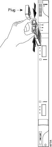
b. ![]() Slide the GBIC through the flap that covers the opening until you hear a click. The click indicates the GBIC is locked into the slot.
Slide the GBIC through the flap that covers the opening until you hear a click. The click indicates the GBIC is locked into the slot.
c. ![]() When you are ready to attach the network fiber-optic cable, remove the protective plug from the GBIC and save the plug for future use.
When you are ready to attach the network fiber-optic cable, remove the protective plug from the GBIC and save the plug for future use.
Step 5 ![]() If you are using a GBIC with a handle:
If you are using a GBIC with a handle:
a. ![]() Remove the protective plug from the SC-type connector.
Remove the protective plug from the SC-type connector.
b. ![]() Grip the sides of the GBIC with your thumb and forefinger and insert the GBIC into the slot on the E1000-2-G, G1000-4, or G1K-4 card.
Grip the sides of the GBIC with your thumb and forefinger and insert the GBIC into the slot on the E1000-2-G, G1000-4, or G1K-4 card.
c. ![]() Lock the GBIC into place by closing the handle down. The handle is in the correct closed position when it does not obstruct access to SC-type connector.
Lock the GBIC into place by closing the handle down. The handle is in the correct closed position when it does not obstruct access to SC-type connector.
d. ![]() Slide the GBIC through the cover flap until you hear a click.
Slide the GBIC through the cover flap until you hear a click.
The click indicates the GBIC is locked into the slot.
Warning ![]() GBICs are Class I laser products. These products have been tested and comply with Class I limits.
GBICs are Class I laser products. These products have been tested and comply with Class I limits.
Warning ![]() Invisible laser radiation may be emitted from the aperture ports of the single-mode fiber optic modules when no cable is connected. Avoid exposure and do not stare into open apertures.
Invisible laser radiation may be emitted from the aperture ports of the single-mode fiber optic modules when no cable is connected. Avoid exposure and do not stare into open apertures.
Step 6 ![]() If you are installing an SFP:
If you are installing an SFP:
a. ![]() Plug the LC duplex connector of the fiber into a Cisco-supported SFP connector.
Plug the LC duplex connector of the fiber into a Cisco-supported SFP connector.
b. ![]() If the new SFP connector has a latch, close the latch over the cable to secure it.
If the new SFP connector has a latch, close the latch over the cable to secure it.
c. ![]() Plug the cabled SFP connector into the ML-series Ethernet, transponder, or muxponder card port until it clicks.
Plug the cabled SFP connector into the ML-series Ethernet, transponder, or muxponder card port until it clicks.
Step 7 ![]() Return to your originating procedure (NTP).
Return to your originating procedure (NTP).
DLP-A470 Remove GBIC or SFP Connectors
Step 1 ![]() Disconnect the network fiber cable from the GBIC SC connector or SFP LC duplex connector. If the SFP connector has a latch securing the fiber cable, pull it upward to release the cable.
Disconnect the network fiber cable from the GBIC SC connector or SFP LC duplex connector. If the SFP connector has a latch securing the fiber cable, pull it upward to release the cable.
Warning ![]() Invisible laser radiation may be emitted from disconnected fibers or connectors. Do not stare into beams or view directly with optical instruments.
Invisible laser radiation may be emitted from disconnected fibers or connectors. Do not stare into beams or view directly with optical instruments.
Step 2 ![]() If you are using a GBIC with clips:
If you are using a GBIC with clips:
a. ![]() Release the GBIC from the slot by simultaneously squeezing the two plastic tabs on each side of it.
Release the GBIC from the slot by simultaneously squeezing the two plastic tabs on each side of it.
b. ![]() Slide the GBIC or SFP out of the Gigabit Ethernet module slot. A flap closes over the GBIC or SFP slot to protect the connector on the Gigabit Ethernet card.
Slide the GBIC or SFP out of the Gigabit Ethernet module slot. A flap closes over the GBIC or SFP slot to protect the connector on the Gigabit Ethernet card.
Step 3 ![]() If you are using a GBIC with a handle:
If you are using a GBIC with a handle:
a. ![]() Release the GBIC by opening the handle.
Release the GBIC by opening the handle.
b. ![]() Pull the handle of the GBIC.
Pull the handle of the GBIC.
c. ![]() Slide the GBIC out of the Gigabit Ethernet card slot. A flap closes over the GBIC slot to protect the connector on the Gigabit Ethernet card.
Slide the GBIC out of the Gigabit Ethernet card slot. A flap closes over the GBIC slot to protect the connector on the Gigabit Ethernet card.
Step 4 ![]() If you are using an SFP:
If you are using an SFP:
a. ![]() If the SFP connector has a latch securing the fiber cable, pull it upward to release the cable.
If the SFP connector has a latch securing the fiber cable, pull it upward to release the cable.
b. ![]() Pull the fiber cable straight out of the connector.
Pull the fiber cable straight out of the connector.
c. ![]() Unplug the SFP connector and fiber from the ML-series Ethernet card.
Unplug the SFP connector and fiber from the ML-series Ethernet card.
d. ![]() Slide the SFP out of the Gigabit Ethernet card slot. A flap closes over the SFP slot to protect the connector on the Gigabit Ethernet card.
Slide the SFP out of the Gigabit Ethernet card slot. A flap closes over the SFP slot to protect the connector on the Gigabit Ethernet card.
Step 5 ![]() Return to your originating procedure (NTP).
Return to your originating procedure (NTP).
NTP-A116 Remove and Replace a Card
Step 1 ![]() If you are not logged into CTC and you need to remove a card, remove the card as described in Step 3. When you log into CTC, troubleshoot the mismatched equipment alarm (MEA) with the Cisco ONS 15454 Troubleshooting Guide.
If you are not logged into CTC and you need to remove a card, remove the card as described in Step 3. When you log into CTC, troubleshoot the mismatched equipment alarm (MEA) with the Cisco ONS 15454 Troubleshooting Guide.
Step 2 ![]() If you are logged into CTC, complete one of the following:
If you are logged into CTC, complete one of the following:
•![]() Complete the "DLP-A191 Delete a Card" task and continue with Step 3.
Complete the "DLP-A191 Delete a Card" task and continue with Step 3.
•![]() Complete the "DLP-A247 Change an Optical Card" task to delete a card and replace it with a different optical card while maintaining existing provisioning.
Complete the "DLP-A247 Change an Optical Card" task to delete a card and replace it with a different optical card while maintaining existing provisioning.
Step 3 ![]() Physically remove the card:
Physically remove the card:
a. ![]() Open the card latches/ejectors.
Open the card latches/ejectors.
b. ![]() Use the latches/ejectors to pull the card forward and away from the shelf.
Use the latches/ejectors to pull the card forward and away from the shelf.
Step 4 ![]() Insert the new card using one of the following procedures as applicable:
Insert the new card using one of the following procedures as applicable:
•![]() 15 Install the Common Control Cards
15 Install the Common Control Cards
•![]() 17 Install the Electrical Cards
17 Install the Electrical Cards
•![]() 18 Install the Ethernet Cards
18 Install the Ethernet Cards
Step 5 ![]() Continue with the "19 Install the Fiber-Optic Cables" procedure.
Continue with the "19 Install the Fiber-Optic Cables" procedure.
Stop. You have completed this procedure.
DLP-A191 Delete a Card
Purpose |
This task deletes a card from CTC. |
Tools/Equipment |
None |
Prerequisite Procedures |
|
Required/As Needed |
As needed |
Onsite/Remote |
Onsite or remote |
Security Level |
None |
Step 1 ![]() On the shelf graphic in CTC, right-click the card that you want to remove and choose Delete Card.
On the shelf graphic in CTC, right-click the card that you want to remove and choose Delete Card.
You cannot delete a card if any of the following conditions apply:
•![]() The card is a TCC+/TCC2 card.
The card is a TCC+/TCC2 card.
•![]() The card is part of a protection group; see the "DLP-A155 Delete a Protection Group" task on page 10-18.
The card is part of a protection group; see the "DLP-A155 Delete a Protection Group" task on page 10-18.
•![]() The card has circuits; see "NTP-A152 Delete Circuits" task on page 9-16.
The card has circuits; see "NTP-A152 Delete Circuits" task on page 9-16.
•![]() The card is part of a BLSR; see the "NTP-A213 Remove a BLSR Node" procedure on page 14-10.
The card is part of a BLSR; see the "NTP-A213 Remove a BLSR Node" procedure on page 14-10.
•![]() The card is being used for timing; see the "DLP-A157 Change the Node Timing Source" task on page 10-19.
The card is being used for timing; see the "DLP-A157 Change the Node Timing Source" task on page 10-19.
•![]() The card has a SONET DCC/GCC termination; see the "NTP-A204 Delete a SONET DCC Termination" procedure on page 10-18.
The card has a SONET DCC/GCC termination; see the "NTP-A204 Delete a SONET DCC Termination" procedure on page 10-18.
Note ![]() If the card that was deleted is not removed from the shelf, it will reboot and re-appear in CTC.
If the card that was deleted is not removed from the shelf, it will reboot and re-appear in CTC.
Step 2 ![]() Return to your originating procedure (NTP).
Return to your originating procedure (NTP).
DLP-A247 Change an Optical Card
Note ![]() You cannot change a multiport card to a card with a smaller number of ports. Do not use this procedure to replace a card with an identical card.Instead, use "DLP-A191 Delete a Card" task.
You cannot change a multiport card to a card with a smaller number of ports. Do not use this procedure to replace a card with an identical card.Instead, use "DLP-A191 Delete a Card" task.
Step 1 ![]() If the card the active card in a 1+1 protection group, switch traffic away from the card:
If the card the active card in a 1+1 protection group, switch traffic away from the card:
a. ![]() Log into a node on the network. If you are already logged in, go to Step b.
Log into a node on the network. If you are already logged in, go to Step b.
b. ![]() Display the CTC node (login) view.
Display the CTC node (login) view.
c. ![]() Click the Maintenance > Protection tabs.
Click the Maintenance > Protection tabs.
d. ![]() Double-click the protection group that contains the reporting card.
Double-click the protection group that contains the reporting card.
e. ![]() Click the active card of the selected group.
Click the active card of the selected group.
f. ![]() Click Switch and Yes in the Confirmation dialog box.
Click Switch and Yes in the Confirmation dialog box.
Step 2 ![]() In CTC, right-click the card that you want to remove and choose Change Card.
In CTC, right-click the card that you want to remove and choose Change Card.
Step 3 ![]() From the Change Card drop-down menu, choose the desired card type and click OK. An MEA appears until you replace the card.
From the Change Card drop-down menu, choose the desired card type and click OK. An MEA appears until you replace the card.
Step 4 ![]() Physically remove the card:
Physically remove the card:
a. ![]() Open the card latches/ejectors.
Open the card latches/ejectors.
b. ![]() Use the latches/ejectors to pull the card forward and away from the shelf.
Use the latches/ejectors to pull the card forward and away from the shelf.
Step 5 ![]() Complete the "16 Install the Optical Cards" procedure.
Complete the "16 Install the Optical Cards" procedure.
Step 6 ![]() Return to your originating procedure (NTP).
Return to your originating procedure (NTP).
NTP-A115 Preprovision a Slot
Step 1 ![]() Log into the ONS 15454. See the "DLP-A60 Log into CTC" task on page 3-23 for instructions. The node (default) view displays. If you are already logged in, continue with Step 2.
Log into the ONS 15454. See the "DLP-A60 Log into CTC" task on page 3-23 for instructions. The node (default) view displays. If you are already logged in, continue with Step 2.
Step 2 ![]() Right-click the empty slot where you will later install a card.
Right-click the empty slot where you will later install a card.
Step 3 ![]() From the Add Card popup menu, choose the card type that will be installed.
From the Add Card popup menu, choose the card type that will be installed.
Note ![]() When you preprovision a slot, the card appears purple in the CTC shelf display, rather than white when a card is physically in the slot.
When you preprovision a slot, the card appears purple in the CTC shelf display, rather than white when a card is physically in the slot.
Step 4 ![]() Continue with the "19 Install the Fiber-Optic Cables" procedure.
Continue with the "19 Install the Fiber-Optic Cables" procedure.
Stop. You have completed this procedure.
NTP-A19 Install the Fiber-Optic Cables
Warning ![]() Class I (21 CFR 1040.10 and 1040.11) and Class 1M (IEC 60825-1 2001-01) laser products.
Class I (21 CFR 1040.10 and 1040.11) and Class 1M (IEC 60825-1 2001-01) laser products.
Warning ![]() Invisible laser radiation may be emitted from the end of the unterminated fiber cable or connector. Do not stare into the beam or view directly with optical instruments. Viewing the laser output with certain optical instruments (for example, eye loupes, magnifiers, and microscopes) within a distance of 100 mm may pose an eye hazard. Use of controls or adjustments or performance of procedures other than those specified may result in hazardous radiation exposure.
Invisible laser radiation may be emitted from the end of the unterminated fiber cable or connector. Do not stare into the beam or view directly with optical instruments. Viewing the laser output with certain optical instruments (for example, eye loupes, magnifiers, and microscopes) within a distance of 100 mm may pose an eye hazard. Use of controls or adjustments or performance of procedures other than those specified may result in hazardous radiation exposure.
Warning ![]() On all optical cards except the OC192 LR/STM64 LH 1550 card, the laser is on even when the optical port is not in service. On the OC192 LR/STM64 LH 1550 card, the laser is active when the card is booted and the safety key is in the on position (labeled 1). The laser is off when the safety key is off (labeled 0).
On all optical cards except the OC192 LR/STM64 LH 1550 card, the laser is on even when the optical port is not in service. On the OC192 LR/STM64 LH 1550 card, the laser is active when the card is booted and the safety key is in the on position (labeled 1). The laser is off when the safety key is off (labeled 0).
Warning ![]() Follow all directions and warning labels when working with optical fibers. To prevent eye damage, never look directly into a fiber or connector.
Follow all directions and warning labels when working with optical fibers. To prevent eye damage, never look directly into a fiber or connector.
Note ![]() Fiber boots are not recommended for the OC192 or the OC48AS because of the downward angle of the optical ports.
Fiber boots are not recommended for the OC192 or the OC48AS because of the downward angle of the optical ports.
Note ![]() You can install the fiber immediately after installing the cards, or wait until you are ready to turn up the network. See Chapter 5, "Turn Up Network."
You can install the fiber immediately after installing the cards, or wait until you are ready to turn up the network. See Chapter 5, "Turn Up Network."
Step 1 ![]() Test the optical receive levels for the cards installed and attenuate accordingly. See Table 2-3 for the minimum and maximum levels.
Test the optical receive levels for the cards installed and attenuate accordingly. See Table 2-3 for the minimum and maximum levels.
|
|
|
|
||
|---|---|---|---|---|
|
|
|
|
|
|
OC3 IR 4/STM1 SH 1310 |
-15 dBm |
-8 dBm |
-28 dBm |
-8 dBm |
OC3IR/STM1SH 1310-8 |
-15 dBm |
-8 dBm |
-28 dBm |
-8 dBm |
OC12 IR/STM4 SH 1310 |
-15 dBm |
-8 dBm |
-28 dBm |
-8 dBm |
OC12 LR/STM4 LH 1310 |
-3 dBm |
+2 dBm |
-28 dBm |
-8 dBm |
OC12 LR/STM4 LH 1550 |
-3 dBm |
+2 dBm |
-28 dBm |
-8 dBm |
OC12 IR/STM4 SH 1310-4 |
-15 dBm |
-8 dBm |
-30 dBm |
-8 dBm |
OC48 IR 1310 |
-5 dBm |
0 dBm |
-18 dBm |
0 dBm |
OC48 LR 1550 |
-2 dBm |
+3 dBm |
-28 dBm |
-8 dBm |
OC48 IR/STM16 SH AS 1310 |
-5 dBm |
0 dBm |
-18 dBm |
0 dBm |
OC48 LR/STM16 LH AS 1550 |
-2 dBm |
+3 dBm |
-28 dBm |
-8 dBm |
OC48 ELR/STM16 EH 100 GHz |
-2 dBm |
0 dBm |
-27 dBm at 1E-12 BER |
-9 dBm |
OC48 ELR/STM16 EH 200 GHz |
-2 dBm |
0 dBm |
-28 dBm |
-8 dBm |
OC192 SR/STM64 IO 1310 |
-6 dBm |
-1 dBm |
-11 dBm |
-1 dBm |
OC192 IR/STM64 SH 1550 |
-1 dBm |
+2 dBm |
-14 dBm |
-1 dBm |
OC192 LR/STM64 LH 1550 |
+7 dBm |
+10 dBm |
-19 dBm |
-10 dBm |
OC192 LR/STM64 LH ITU 15xx.xx |
+3 dBm |
+6 dBm |
-22 dBm |
-9 dBm |
TXP_MR_10G (trunk side) |
-16 dBm1 |
+3 dBm1 |
-24 dBm |
-8 dBm |
TXP_MR_10G (client side) |
-6 dBm |
-1 dBm |
-14 dBm |
-1 dBm |
MXP_2.5G_10G (trunk side) |
-16 dBm1 |
+3 dBm1 |
-24 dBm |
-8 dBm |
MXP_2.5G_10G (client side) |
-5 dBm |
0 dBm |
depends on SFP |
depends on SFP |
1 On transponder and muxponder cards, the optical output power on the trunk side can be configured from —16 to +3 dBm with an accuracy of +/-0.5 dB. |
Step 2 ![]() As needed, complete the "DLP-A207 Install Fiber-Optic Cables on the LGX Interface" task.
As needed, complete the "DLP-A207 Install Fiber-Optic Cables on the LGX Interface" task.
Note ![]() Inspect and clean all fiber connectors thoroughly. See the "NTP-A112 Clean Fiber Connectors" procedure on page 15-23 for instructions. Dust particles can degrade performance. Put caps on any fiber connectors that are not used.
Inspect and clean all fiber connectors thoroughly. See the "NTP-A112 Clean Fiber Connectors" procedure on page 15-23 for instructions. Dust particles can degrade performance. Put caps on any fiber connectors that are not used.
Step 3 ![]() Complete the "DLP-A42 Install Fiber-Optic Cables on OC-N Cards" task.
Complete the "DLP-A42 Install Fiber-Optic Cables on OC-N Cards" task.
Note ![]() To install fiber-optic cables on an Ethernet card GBIC, see the "DLP-A469 Install GBIC or SFP Connectors" task.
To install fiber-optic cables on an Ethernet card GBIC, see the "DLP-A469 Install GBIC or SFP Connectors" task.
Step 4 ![]() As needed, complete the "DLP-A43 Install Fiber-Optic Cables for Path Protection Configurations" task.
As needed, complete the "DLP-A43 Install Fiber-Optic Cables for Path Protection Configurations" task.
Step 5 ![]() As needed, complete the "DLP-A44 Install Fiber-Optic Cables for BLSR Configurations" task.
As needed, complete the "DLP-A44 Install Fiber-Optic Cables for BLSR Configurations" task.
Step 6 ![]() Complete the "DLP-A45 Install the Fiber Boot" task.
Complete the "DLP-A45 Install the Fiber Boot" task.
Step 7 ![]() Complete the "DLP-A46 Route Fiber-Optic Cables" task.
Complete the "DLP-A46 Route Fiber-Optic Cables" task.
Step 8 ![]() Continue with the "20 Replace the Front Door" procedure.
Continue with the "20 Replace the Front Door" procedure.
Stop. You have completed this procedure.
DLP-A207 Install Fiber-Optic Cables on the LGX Interface
Note ![]() Inspect and clean all fiber connectors thoroughly. See the "NTP-A112 Clean Fiber Connectors" procedure on page 15-23 for instructions. Dust particles can degrade performance. Put caps on any fiber connectors that are not used.
Inspect and clean all fiber connectors thoroughly. See the "NTP-A112 Clean Fiber Connectors" procedure on page 15-23 for instructions. Dust particles can degrade performance. Put caps on any fiber connectors that are not used.
Step 1 ![]() Align the keyed ridge of the cable connector with the receiving SC connector on the LGX faceplate connection point. Each module supports at least one transmit and one receive connector to create an optical carrier port.
Align the keyed ridge of the cable connector with the receiving SC connector on the LGX faceplate connection point. Each module supports at least one transmit and one receive connector to create an optical carrier port.
Step 2 ![]() Gently insert the cable connector into the faceplate connection point until the connector snaps into place.
Gently insert the cable connector into the faceplate connection point until the connector snaps into place.
Step 3 ![]() Connect the fiber optic cable to the OC-N card. See the "DLP-A42 Install Fiber-Optic Cables on OC-N Cards" task.
Connect the fiber optic cable to the OC-N card. See the "DLP-A42 Install Fiber-Optic Cables on OC-N Cards" task.
Step 4 ![]() Return to your originating procedure (NTP).
Return to your originating procedure (NTP).
DLP-A42 Install Fiber-Optic Cables on OC-N Cards
Purpose |
This task installs fiber-optic cables on optical (OC-N) cards. |
Tools/Equipment |
Fiber-optic cables |
Prerequisite Procedures |
|
Required/As Needed |
Required |
Onsite/Remote |
Onsite |
Security Level |
None |
Note ![]() Inspect and clean all fiber connectors thoroughly. See the "NTP-A112 Clean Fiber Connectors" procedure on page 15-23 for instructions. Dust particles can degrade performance. Put caps on any fiber connectors that are not used.
Inspect and clean all fiber connectors thoroughly. See the "NTP-A112 Clean Fiber Connectors" procedure on page 15-23 for instructions. Dust particles can degrade performance. Put caps on any fiber connectors that are not used.
Note ![]() The Cisco OC-3 IR/STM-1 SH, OC-12 IR/STM-4 SH, and OC-48 IR/STM-16 SH interface optics, all working at 1310 nm, are optimized for the most widely used SMF-28 fiber, available from many suppliers.
The Cisco OC-3 IR/STM-1 SH, OC-12 IR/STM-4 SH, and OC-48 IR/STM-16 SH interface optics, all working at 1310 nm, are optimized for the most widely used SMF-28 fiber, available from many suppliers.
Note ![]() Corning MetroCor fiber is optimized for optical interfaces that transmit at 1550 nm or in the C and L DWDM windows. This fiber targets interfaces with higher dispersion tolerances than those found in OC-3 IR/STM-1 SH, OC-12 IR/STM-4 SH, and OC-48 IR/STM-16 SH interface optics. If you are using Corning MetroCor fiber, OC-3 IR/STM-1 SH, OC- 12 IR/STM-4 SH, and OC-48 IR/STM-16 SH interface optics will become dispersion limited before they will become attenuation limited. In this case, consider using OC-3 LR/STM-1 LH, OC-12 LR/STM-4 LH, and OC-48 LR/STM-16 LH cards instead of OC-3 IR/STM-1 SH, OC-12 IR/STM-4 SH, and OC-48 IR/STM-16 SH cards.
Corning MetroCor fiber is optimized for optical interfaces that transmit at 1550 nm or in the C and L DWDM windows. This fiber targets interfaces with higher dispersion tolerances than those found in OC-3 IR/STM-1 SH, OC-12 IR/STM-4 SH, and OC-48 IR/STM-16 SH interface optics. If you are using Corning MetroCor fiber, OC-3 IR/STM-1 SH, OC- 12 IR/STM-4 SH, and OC-48 IR/STM-16 SH interface optics will become dispersion limited before they will become attenuation limited. In this case, consider using OC-3 LR/STM-1 LH, OC-12 LR/STM-4 LH, and OC-48 LR/STM-16 LH cards instead of OC-3 IR/STM-1 SH, OC-12 IR/STM-4 SH, and OC-48 IR/STM-16 SH cards.
Note ![]() With all fiber types, network planners/engineers should review the relative fiber type and optics specifications to determine attenuation, dispersion, and other characteristics to ensure appropriate deployment.
With all fiber types, network planners/engineers should review the relative fiber type and optics specifications to determine attenuation, dispersion, and other characteristics to ensure appropriate deployment.
Step 1 ![]() Align the keyed ridge of the cable connector with the receiving SC connector on the faceplate connection point. Each card supports at least one transmit and one receive connector to create an optical carrier port. Figure 2-2 shows the cable location.
Align the keyed ridge of the cable connector with the receiving SC connector on the faceplate connection point. Each card supports at least one transmit and one receive connector to create an optical carrier port. Figure 2-2 shows the cable location.
Figure 2-2 Installing Fiber-Optic Cables
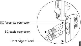
Note ![]() The OC12 IR/STM4 SH 1310-4 card faceplate has four ports.
The OC12 IR/STM4 SH 1310-4 card faceplate has four ports.
Step 2 ![]() Gently insert the cable connector into the faceplate connection point until the connector snaps into place.
Gently insert the cable connector into the faceplate connection point until the connector snaps into place.
Step 3 ![]() If you are installing fiber-optic cables on a OC12 IR/STM4 SH 1310-4 card, repeat Steps 1 and 2 until all SC connectors are in place.
If you are installing fiber-optic cables on a OC12 IR/STM4 SH 1310-4 card, repeat Steps 1 and 2 until all SC connectors are in place.
Step 4 ![]() Return to your originating procedure (NTP).
Return to your originating procedure (NTP).
DLP-A43 Install Fiber-Optic Cables for Path Protection Configurations
Purpose |
This task installs the fiber-optic cables to the east and west path protection ports at each node. See Chapter 5, "Turn Up Network" to provision and test path protection configurations. |
Tools/Equipment |
Fiber-optic cables |
Prerequisite Procedures |
|
Required/As Needed |
Required |
Onsite/Remote |
Onsite |
Security Level |
None |
Note ![]() To avoid error, connect fiber-optic cable so that the farthest slot to the right represents the east port, and the farthest slot to the left represents the west port. Fiber connected to an east port at one node must plug into the west port on an adjacent node.
To avoid error, connect fiber-optic cable so that the farthest slot to the right represents the east port, and the farthest slot to the left represents the west port. Fiber connected to an east port at one node must plug into the west port on an adjacent node.
Note ![]() Inspect and clean all fiber connectors thoroughly. See the "NTP-A112 Clean Fiber Connectors" procedure on page 15-23 for instructions. Dust particles can degrade performance. Put caps on any fiber connectors that are not used.
Inspect and clean all fiber connectors thoroughly. See the "NTP-A112 Clean Fiber Connectors" procedure on page 15-23 for instructions. Dust particles can degrade performance. Put caps on any fiber connectors that are not used.
Step 1 ![]() Plan your fiber connections. Use the same plan for all path protection nodes.
Plan your fiber connections. Use the same plan for all path protection nodes.
Step 2 ![]() Plug the fiber into the transmit (Tx) connector of an OC-N card at one node and plug the other end of the fiber into the receive (Rx) connector of an OC-N card at the adjacent node. The card displays a SF LED if the transmit and receive fibers are mismatched (one fiber connects a receive port on one card to a receive port on another card, or the same situation with transmit ports).
Plug the fiber into the transmit (Tx) connector of an OC-N card at one node and plug the other end of the fiber into the receive (Rx) connector of an OC-N card at the adjacent node. The card displays a SF LED if the transmit and receive fibers are mismatched (one fiber connects a receive port on one card to a receive port on another card, or the same situation with transmit ports).
Step 3 ![]() Repeat Step 2 until you have configured the ring.
Repeat Step 2 until you have configured the ring.
Figure 2-3 shows fiber connections for a four-node path protection with trunk (span) cards in Slot 5 (west) and Slot 12 (east). If you are creating a path protection dual ring interconnect, Figure 2-4 shows a traditional dual ring interconnect example. Figure 2-5 shows an integrated dual ring interconnect example.
Figure 2-3 Connecting Fiber to a Four-Node Path Protection
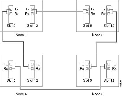
Figure 2-4 Connecting Fiber to an Eight-Node Traditional Path Protection Dual-Ring Interconnect
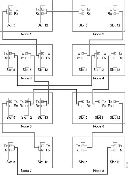
Figure 2-5 Connecting Fiber to a Six-Node Integrated Path Protection Dual-Ring Interconnect
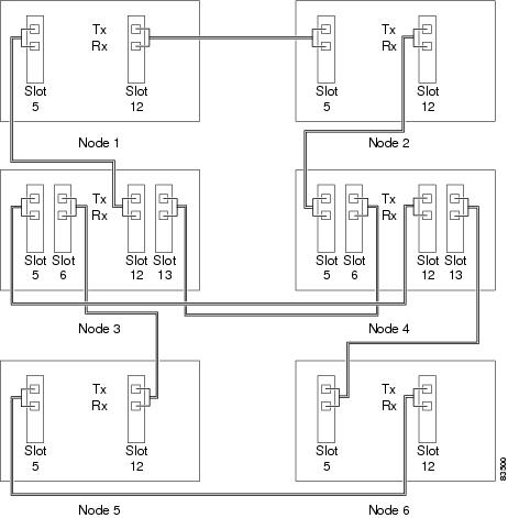
Step 4 ![]() Return to your originating procedure (NTP).
Return to your originating procedure (NTP).
DLP-A44 Install Fiber-Optic Cables for BLSR Configurations
Purpose |
This task installs the fiber-optics to the east and west BLSR ports at each node. See Chapter 5, "Turn Up Network" to provision and test BLSR configurations. |
Tools/Equipment |
Fiber-optic cables |
Prerequisite Procedures |
|
Required/As Needed |
As needed |
Onsite/Remote |
Onsite |
Security Level |
None |
Note ![]() To avoid error, connect fiber-optic cable so that the farthest slot to the right represents the east port, and the farthest slot to the left represents the west port. Fiber connected to an east port at one node must plug into the west port on an adjacent node.
To avoid error, connect fiber-optic cable so that the farthest slot to the right represents the east port, and the farthest slot to the left represents the west port. Fiber connected to an east port at one node must plug into the west port on an adjacent node.
Note ![]() Inspect and clean all fiber connectors thoroughly. See the "NTP-A112 Clean Fiber Connectors" procedure on page 15-23 for instructions. Dust particles can degrade performance. Put caps on any fiber connectors that are not used.
Inspect and clean all fiber connectors thoroughly. See the "NTP-A112 Clean Fiber Connectors" procedure on page 15-23 for instructions. Dust particles can degrade performance. Put caps on any fiber connectors that are not used.
Step 1 ![]() Plan your fiber connections. Use the same plan for all BLSR nodes.
Plan your fiber connections. Use the same plan for all BLSR nodes.
Step 2 ![]() Plug the fiber into the transmit (Tx) connector of an OC-N card at one node and plug the other end into the receive (Rx) connector of an OC-N card at the adjacent node. The card displays a SF LED if the transmit and receive fibers are mismatched.
Plug the fiber into the transmit (Tx) connector of an OC-N card at one node and plug the other end into the receive (Rx) connector of an OC-N card at the adjacent node. The card displays a SF LED if the transmit and receive fibers are mismatched.
Note ![]() Do not mix working and protect card connections when connecting a four-fiber BLSR. The BLSR does not function if working and protect cards are interconnected. See Figure 2-7 for an example of correct four-fiber BLSR cabling.
Do not mix working and protect card connections when connecting a four-fiber BLSR. The BLSR does not function if working and protect cards are interconnected. See Figure 2-7 for an example of correct four-fiber BLSR cabling.
Step 3 ![]() Repeat Step 2 until you have configured the ring.
Repeat Step 2 until you have configured the ring.
Figure 2-6 shows fiber connections for a two-fiber BLSR with trunk cards in Slot 5 (west) and Slot 12 (east).
Figure 2-6 Connecting Fiber to a Four-Node, Two-Fiber BLSR
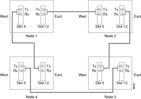
Figure 2-7 shows fiber connections for a four-fiber BLSR. Slot 5 (west) and Slot 12 (east) carry the working traffic. Slot 6 (west) and Slot 13 (east) carry the protect traffic.
Figure 2-7 Connecting Fiber to a Four-Node, Four-Fiber BLSR
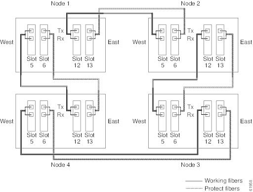
Step 4 ![]() Return to your originating procedure (NTP).
Return to your originating procedure (NTP).
DLP-A45 Install the Fiber Boot
Note ![]() You can install the fiber boots on the fiber-optic cables before or after the fibers are attached to the optical card.
You can install the fiber boots on the fiber-optic cables before or after the fibers are attached to the optical card.
Note ![]() The fiber boot does not support the OC-48 IR/STM-16 SH AS 1310, OC-48 LR/STM-16 LH AS 1550, and OC-192 LR/STM64 LH 1550 cards. The boots are not necessary for these cards because of the angled SC connectors on the cards.
The fiber boot does not support the OC-48 IR/STM-16 SH AS 1310, OC-48 LR/STM-16 LH AS 1550, and OC-192 LR/STM64 LH 1550 cards. The boots are not necessary for these cards because of the angled SC connectors on the cards.
Note ![]() If you are installing an OC3IR/STM1SH 1310-8 card, you must use a fiber clip instead of a fiber boot on the port 8 Rx fiber connector.
If you are installing an OC3IR/STM1SH 1310-8 card, you must use a fiber clip instead of a fiber boot on the port 8 Rx fiber connector.
Step 1 ![]() Position the open slot of the fiber boot underneath the fiber cable.
Position the open slot of the fiber boot underneath the fiber cable.
Step 2 ![]() Push the fiber cable down into the fiber boot. Figure 2-8 shows the fiber boot attachment.
Push the fiber cable down into the fiber boot. Figure 2-8 shows the fiber boot attachment.
Step 3 ![]() Twist the fiber boot to lock the fiber cable into the tail end of the fiber boot.
Twist the fiber boot to lock the fiber cable into the tail end of the fiber boot.
Step 4 ![]() Slide the fiber boot forward along the fiber cable until the fiber boot fits snugly onto the end of the SC cable connector.
Slide the fiber boot forward along the fiber cable until the fiber boot fits snugly onto the end of the SC cable connector.
Figure 2-8 Attaching a Fiber Boot
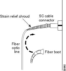
Step 5 ![]() Return to your originating procedure (NTP).
Return to your originating procedure (NTP).
DLP-A46 Route Fiber-Optic Cables
Purpose |
This task describes how to route fiber-optic cables. |
Tools/Equipment |
None |
Prerequisite Procedures |
Any of the following: 207 Install Fiber-Optic Cables on the LGX Interface 42 Install Fiber-Optic Cables on OC-N Cards 43 Install Fiber-Optic Cables for Path Protection Configurations |
Required/As Needed |
Required |
Onsite/Remote |
Onsite |
Security Level |
None |
Step 1 ![]() Open the fold-down front door on the cable-management tray.
Open the fold-down front door on the cable-management tray.
Step 2 ![]() Route the fiber cable on the card faceplate through the fiber clip on the faceplate. Fiber clips are factory-attached to the faceplate of the optical card.
Route the fiber cable on the card faceplate through the fiber clip on the faceplate. Fiber clips are factory-attached to the faceplate of the optical card.
GBICs do not have fiber clips; therefore, if you are routing optical cable from an E1000-2-G, E1000-2, or G-Series cards, skip to Step 3.
Step 3 ![]() Route the fiber cables into the cable-management tray.
Route the fiber cables into the cable-management tray.
Step 4 ![]() Route the fiber cables out either side of the cable-management tray through the cutouts on each side of the shelf assembly. Use the reversible fiber guides to route cables out the desired side.
Route the fiber cables out either side of the cable-management tray through the cutouts on each side of the shelf assembly. Use the reversible fiber guides to route cables out the desired side.
Step 5 ![]() Close the fold-down front door when all fiber cables in the front compartment are properly routed.
Close the fold-down front door when all fiber cables in the front compartment are properly routed.
Step 6 ![]() Return to your originating procedure (NTP).
Return to your originating procedure (NTP).
NTP-A20 Replace the Front Door
Note ![]() Watch to make sure that you do not crimp any fiber cables that are connected to the optical cards. Some might not have the fiber boot attached.
Watch to make sure that you do not crimp any fiber cables that are connected to the optical cards. Some might not have the fiber boot attached.
Step 1 ![]() Insert the front door into the hinges on the shelf assembly.
Insert the front door into the hinges on the shelf assembly.
Step 2 ![]() Attach one end of the ground strap terminal lug (72-3622-01) to the male stud on the inside of the door. Attach and tighten the #6 Kepnut (49-0600-01) using the open-end wrench. See Figure 2-9.
Attach one end of the ground strap terminal lug (72-3622-01) to the male stud on the inside of the door. Attach and tighten the #6 Kepnut (49-0600-01) using the open-end wrench. See Figure 2-9.
Figure 2-9 Installing the Door Ground Strap Retrofit Kit
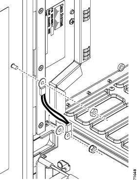
Step 3 ![]() Attach the other end of the ground strap to the longer screw on the fiber guide.
Attach the other end of the ground strap to the longer screw on the fiber guide.
a. ![]() Attach the lock washer.
Attach the lock washer.
b. ![]() Attach the terminal lug.
Attach the terminal lug.
c. ![]() Using the open-end wrench, attach and tighten the #4 Kepnut (49-0337-01) on the terminal lug.
Using the open-end wrench, attach and tighten the #4 Kepnut (49-0337-01) on the terminal lug.
Note ![]() To avoid interference with the traffic (line) card, make sure the ground strap is in a flat position when the door is open. To move the ground strap into a flat position, rotate the terminal lug counterclockwise before tightening the Kepnut.
To avoid interference with the traffic (line) card, make sure the ground strap is in a flat position when the door is open. To move the ground strap into a flat position, rotate the terminal lug counterclockwise before tightening the Kepnut.
Step 4 ![]() Replace the left cable-routing channel.
Replace the left cable-routing channel.
Step 5 ![]() Using a Phillips screwdriver, insert and tighten the screws for the cable-routing channel.
Using a Phillips screwdriver, insert and tighten the screws for the cable-routing channel.
Figure 2-10 shows the shelf assembly with the front door and ground strap installed.
Figure 2-10 Shelf Assembly with Door Ground Strap Retrofit Kit Installed
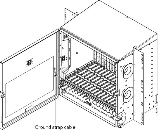
Step 6 ![]() Swing the door closed.
Swing the door closed.
Note ![]() The ONS 15454 comes with a pinned hex key tool for locking and unlocking the front door. Turn the key counterclockwise to unlock the door and clockwise to lock it.
The ONS 15454 comes with a pinned hex key tool for locking and unlocking the front door. Turn the key counterclockwise to unlock the door and clockwise to lock it.
Stop. You have completed this procedure.
 Feedback