
Table Of Contents
Configuring Topology Discovery
Configuring AutoRoute Topology
Checking the CWM Workstation File System
svplus/config/network.conf file
CWM Gateway Configuration File
Modifying the SNMP Community String
Modifying the svplus.conf File
Modifying the process.conf File
Setting Up the IP Address on an Cisco MGX 8850, Release 2 Switch
Procedure for Releases up to and including 2.1.60
Procedure for Releases 2.1.70 and later.
Setting Up ATM WAN Connections
Configuring PNNI using CiscoView
Configuration
This chapter provides information about the configuration required for the CWM workstation.
Configuring Topology Discovery
The network.conf file, located in the /usr/users/svplus/config/ directory, is used to specify the network(s) to be discovered and managed by CWM. Basically this file describes the routing protocol, the gateway address to the network, and whether in-band or out-of-band management is used.
The format of the file depends upon the type of network of which there are three as follows.
•
AutoRoute network
•
•
To view the /usr/users/svplus/config/network.conf file, enter the following command:
host% more /usr/users/svplus/config/network.confConfiguring AutoRoute Topology
To configure the CWM workstation to use AutoRoute discovery. Modify the network.conf file in the /usr/users/svplus/config directory as shown in the following example.

Note
nmsbpx02on a network designatednetwork1.
NETWORK:network1GATEWAYS:nmsbpx02DISCOVERY PROTOCOL:AUTOROUTEIP REACHABILITY FLAG:NWIP_ONOPTIONAL:"TIMEOUT=7, RETRANSMIT=6, THROTTLE=0, ACKNOWLEDGE=30, BLOCKSIZE=1024"Configuring PNNI Topology
Use the Topology Configurator to provide information required to communicate with the nodes. Also use the configurator to specify Network IP.
Note
Configuring PXM45 Cards
To configure a PXM45 card, telnet to the card and enter the following commands:
pxm45> shmsimulateresetReason 0pxm45> deltree "C:DB2"
Note
anotherPXM> addcontroller 2 i 2 7 "pxm45 controller"
Note
anotherPXM> addpnport 9:1.1:1anotherPXM> cnfpnportsig 9:1.1:1 -nniver pnni 10
Note
Configuring AXSM Cards
To configure a AXSM card, telnet to the card and enter the following commands:
specificAXSM.a> cnfingsct -sct 5specificAXSM.a> upln 1.1specificAXSM.a> addport 1 1.1 9600 96000 5 2specificAXSM.a> addpart 1 1 2 9600 96000 9600 96000 33 4095 33 65535 3 512specificAXSM.a> cnfilmi -if 1 -id 1 -ilmi 1 -trap 1specificAXSM.a> dspportsspecificAXSM.a> dsppartsspecificAXSM.a> dspilmisspecificAXSM.a> cc 7specificAXSM.a> dsppnportsspecificAXSM.a> uppnport 9:1.1:1specificAXSM.a> ipifconfig atm0 <ipaddress node NWIP>specificAXSM.a> cnffname <sysname>
Note
Configuring Hybrid Topology
To configure CWM for Hybrid networks (AutoRoute and PNNI), the file has the following format.
NETWORK:Network1 (a name for CWM to identify the network)AR-GATEWAYS:sj123456 (the name or IP address of the gateway to the Auroroute section of the network)PNNI-GATEWAYS:sj123456 (the name or IP address of the gateway to the PNNI section of the network)DISCOVERY PROTOCOL:HYBRID (the discovery protocol, in this case always HYBRID)IP REACHABILITY FLAG:NWIP_OFF (specifies in-band or out-of-band management)OPTIONAL:"TIMEOUT = 7, RETRANSMIT = 6, THROTTLE = 0, ACKNOWLEDGE = 30, BLOCKSIZE = 1024" (the optional field is used to specify parameters if the desired value is different from the default value,Check that the mnemonic of the gateway node is correct. Also, for AutoRoute nodes, check the IP Reachability Flag is correct.
Configuring Standalone Nodes
In a stand alone environment, the network.conf file does not require modification. Use the Topology Configurator to provide the following information:
•
•
•
Note
To add a new node, complete the following steps:
Step 1
cd /usr/users/svplus/java/binStep 2
The Network Configurator main window appears, displaying the options to add, delete, and modify nodes.
Step 3
Step 4
Step 5
A Node Dialog box appears after selecting Add from the Node menu. The Node Dialog box contains two tab windows, Node and Mode.
Step 6
Step 7
Note
Step 8
The Network Configurator validates the new node by ensuring its IP address and unique node name. The node will be displayed in the Network Configurator main window if the node information is valid.
Step 9
Step 10
Note
All MGX 8850 nodes will be displayed in both the standalone view and the integrated view.
For more information on configuring standalone MGX 8850 nodes for management by CWM, refer to Appendix B of the Cisco WAN Manager User's Guide, Release 11.
Checking the CWM Workstation File System
At the CWM workstation, log in as user root, and examine the following files.
•
•
•
•
•
•
•
•
•
Note
/etc/hosts
Examine the /etc/hosts file and check that the file contains a nodename and IP address for all nodes. The IP address should be one that CWM can use for network discovery (see following paragraphs). Enter the correct nodenames and addresses for any missing nodes.
To view the /etc/hosts file, enter the following command:
host% more /etc/hostsUse vi Editor to enter items into the file.
IPX and MGX (Rel 1.x, 2.0 and up to 2.1.60) Nodes
For each node:
Enter the ATM0 or NWIP address and the node name.
Enter the LnPci0 or LANIP address and the nodename followed by an identifier such as -l, or -lan).
Example:
172.70.207.9	mgx1
192.0.0.9	mgx1-l
MGX (Rel 2.1.70 and above) Nodes
For each node:
Enter the IP address used in option 8 of the cnfndparms command. This address can be displayed at the node by entering the dspndparms command.
Example:
172.70.209.9 mgx4BPX Nodes
For each node:
Enter the node's IP address and the node name.
Example:
192.0.0.8 bpx1Example Host File
As an example, a hosts file might look like the following example:
# MGX Rel 1, 2.0, up to 2.1.60 nodes172.70.207.9 mgx1 192.0.0.9 mgx1-l172.70.207.6 mgx2 192.0.0.6 mgx2-l172.70.207.4 mgx3 192.0.0.4 mgx3-l##MGX Rel 2.1.70 and up nodes172.70.209.9 mgx4172.70.209.8 mgx5172.70.209.7 mgx6172.70.209.6 mgx7##BPX nodes192.0.0.8 bpx1192.0.0.9 bpx2192.0.0.10 bpx3/etc/netmasks
Examine the /etc/netmasks file for all subnet and netmask entries. To view the /etc/netmasks file, enter the following command:
host% more /etc/netmasks/etc/rc2.d/S72inetsvc
Examine the /etc/rc2.d/S72inetsvc file to ensure that the IP relay address points to the gateway node. To view the /etc/rc2.d/S72inetsvc file, enter the following command:
host% more /etc/rc2.d/S72inetsvcUse the vi Editor to open the S72inetsvc file and find the following line:
/usr/sbin/route add -interface -netmask "224.0.0.0" "224.0.0.0" "$mcastif")&Add the following line directly below that line
/usr/sbin/route add net 10.10.10.0 209.165.200.225  1  (use your site's valid IP
addresses)
Note
/etc/defaultrouter
Examine the /etc/defaultrouter file. To view the /etc/defaultrouter file, enter the following command:
host% more /etc/defaultrouter
Note
If the router IP address is not currently in the file, use the vi Editor to add a line containing the IP address of the default router to which the CWM workstation is attached.
Note
usr/users/svplus/.cshrc
Use the vi editor to modify .cshrc as follows:
vi usr/users/svplus/.cshrc
Change the line:
setenv PATH$ORBIXROOT/bin:$PATH
to
setenv PATH$ORBIXROOT/bin:/opt/NSCPcom:$PATHAdd the following lines to the end of the file.
setenv PATH "netscape path":$PATH
setenv MOZILLA_HOME "netscape path"
Exit vi.svplus/config/network.conf file
The network.conf file is located in the /usr/users/svplus/config directory.
The user should modify this file to specify networks parameters for each network to be discovered and managed.This file can describe multiple networks where each network can be any one of the following types.
•
•
•
For each network specified in the network.conf file, its entry consists of the following fields.
•
•
•
•
•
•
NETWORK
The NETWORK field has the following format.
NETWORK: <Network Name>
When describing a network's parameters, NETWORK must be the first parameter.
The Network name cannot have more than 10 characters and cannot contain a space.
Note
NETWORK ID
The NETWORK ID field has the following format.
NETWORK_ID: <Network ID>
Network ID is optional. If it is specified, the Network ID must be a unique numeric value in the range in [1, 32000].
Note
GATEWAYS
The GATEWAYS field has the following formats.
GATEWAYS: <Gateway Name(s)> (used for AutoRoute and PNNI).
AR-GATEWAYS: <Gateway Name> (used for AutoRoute segments in a Hybrid network type).
PNNI-GATEWAYS: <Gateway Name(s)> (used for PNNI segments in a Hybrid network type).
The user should enter the name(s) of any gateways that CWM is to use for network discovery.
The rules for gateways parameters depend upon the network type.
AutoRoute
Use the GATEWAYS: <Gateway Name> format and specify one (and only one) network node to be used as the AutoRoute gateway.
PNNI
Use the GATEWAYS: <Gateway Name> format and specify one or more network nodes to be used as PNNI gateways. If more than one gateway is specified for the network, the names should be separated by commas.
Hybrid
This field is used to specify which gateways should be used for the AutoRoute and PNNI segments of the network.
Use the PNNI-GATEWAYS: <Gateway Names> format to specify one or more network nodes to be used as PNNI gateways. If more than one gateway is specified for the PNNI segment, the names should be separated by commas.
Use the AR-GATEWAYS: <Gateway Names> format and specify one (and only one) network node to be used as an AutoRoute gateway.
Note
.DISCOVERY PROTOCOL
This field is used to specify the network type and has the following format.
DISCOVERY PROTOCOL: <Protocol Name>
The Protocol Name can be either AUTOROUTE or PNNI or HYBRID.
AUTOROUTE is used to discover Auto Route networks .
PNNI is used for ILMI or PNNI discovery of PNNI networks.
HYBRID is used to discover networks that contain both AutoRoute and PNNI segments.
IP REACHABILITY FLAG
The IP REACHABILITY FLAG field is used to specify which IP address method is to be used for managing network nodes. This field is used for AutoRoute networks and Hybrid AutoRoute segments only. It is ignored for PNNI networks or segments.The IP REACHABILITY FLAG field has the following format.
IP REACHABILITY FLAG:<Ip Flag>
IP Flag can be set to NWIP_ON or NWIP_OFF or LANIP.
NWIP_ON — All the routing nodes in the network are managed using their nw ip addresses.
NWIP_OFF — All the routing nodes in the network are managed through the Gateway. The Gateway then routes packets to the individual routing nodes on the corresponding routing trunks.
LANIP — All the nodes in the network are managed using Lan IP. The AUTOROUTE Gateway node is always managed using the LAN IP. By specifying "LANIP", all management traffic (including link0/link1, snmp and tftp) is sent to each node (routing node or feeders) using their Lan IP addresses.
If NWIP is set to ON or OFF, management messages use the managed network for delivery and are therefore considered to be in-band. A setting of LAN IP, on the other hand, uses a separate LAN (or LAN emulation) network for message delivery and is therefore considered to be out-of-band.
OPTIONAL
The OPTIONAL field is used to specify a number of options associated with the IP REACHABILITY FLAG and has the following format.
OPTIONAL: "List of Parameters for Auto Route Networks"
This field is mandatory for AutoRoute networks and AutoRoute segments in Hybrid networks. If this field is not specified, Auto Route networks and segments WILL NOT be discovered
OPTIONAL does not apply for PNNI networks and is ignored.
The OPTIONAL field has five sub-fields (options) as follows:
•
•
•
•
•
TIMEOUT
Link timeout value. The amount of time to wait before resending a message to an Cisco IGX 8400 and Cisco BPX 8600 when a response is not received. Default value is 7.
RETRANSMIT
Link retry count. The number of times CWM will retransmit a message before it declares the link down. Default value is 6.
THROTTLE
Download throttling timeout value. Default value is 0
ACKNOWLEDGE
ACK timeout value used during the download process. When an acknowledgment to a configuration message sent to an Cisco IGX 8400, or Cisco BPX 8600 is not received within this time period, the message is sent again. Default value is 30.
BLOCKSIZE
Block size used for an Cisco IGX 8400, or Cisco BPX 8600 configuration upload. Default value is 1024.
Note
Network.conf Examples
1. Discover an AutoRoute Network
NETWORK:Network1
GATEWAYS:B8650_SJ
DISCOVERY PROTOCOL:AUTOROUTE
IP REACHABILITY FLAG:NWIP_ON
OPTIONAL:"TIMEOUT = 7, RETRANSMIT = 6, THROTTLE = 0, ACKNOWLEDGE = 30, BLOCKSIZE = 1024"
2. Discover a PNNI network
NETWORK:Network2
GATEWAYS:M8850_LA
DISCOVERY PROTOCOL:PNNI
Note
3. Discover a HYBRID Network
#NETWORK:Network3
#PNNI-GATEWAYS:M8850_LA, M8850_CH
#AR-GATEWAYS:B8650_LA
#DISCOVERY PROTOCOL:HYBRID
#IP REACHABILITY FLAG:NWIP_ON
#OPTIONAL:"TIMEOUT = 7, RETRANSMIT = 6, THROTTLE = 0, ACKNOWLEDGE = 30, BLOCKSIZE = 1024"
CWM Gateway Configuration File
If the upgraded CWM workstation is part of a multiple CWM gateway configuration, check the CWMGateway.conf file and ensure that the DomainGatewayList contains all the stations in the Gateway domain.
For example:
host% cd usr/users/svplus/confighost% more CWMGateway.confCheck the DomainGatewayList portion of this file.
## Default: DomainGatewayList
## Usage: DomainGateWayList tmonda dilbag sgharat
DomainGatewayList CWM1 CWM2 CWM3
In this example, CWM1, CWM2, and CWM3 are the names of the CWM gateways.
/system
Change directory to /system and enter the ls command. Check to see that all required HPOV PSOV_XXXXX patches have been installed.
# cd /system# ls/etc/system
Check to see that the CWM installation process added the semaphores required for Solaris and HP OpenView operability
(set semsys:seminfo_semmsl=30).forceload: sys/shmsysforceload: sys/semsysset semsys:seminfo_semaem=16384set semsys:seminfo_semmap=66set semsys:seminfo_semmni=4096set semsys:seminfo_semmns=4096set semsys:seminfo_semmnu=4096set semsys:seminfo_semume=64set semsys:seminfo_semvmx=32767set semsys:seminfo_semmsl=30set shmsys:shminfo_shmmax=268435456set shmsys:shminfo_shmmin=100set shmsys:shminfo_shmmni=100set shmsys:shminfo_shmseg=100Reboot the Workstation
After completing the configuration, reboot the workstation.
# sync ;sync ;rebootModifying the SNMP Community String
In Cisco IGX 8400 and Cisco BPX 8600 nodes require that you modify the SNMP Community string using the cnfsnmp command. For example:
host% cnfsnmp <getme> <setme> <trapme>In addition, you must modify two files on the CWM workstation in directory /usr/users/svplus/config:
•
•
Modifying the svplus.conf File
As user root on the CWM workstation, use vi or some other editor to edit the /usr/users/svplus/config/svplus.conf file and set SV_COMMUNITY to getme and set SV_SETCOMMUNITY to setme.
The svplus.conf file should look like the following example:
# Community name for BPX and IPX#SV_COMMUNITY=getmeSV_SETCOMMUNITY=setme
Note
Modifying the process.conf File
As user svplus on the CWM workstation, edit the /usr/users/svplus/config/process.conf file. The process.conf file should have a line like the following example:
cmgrd on . cmgrd -c setme -C getme -i 5
Note
Setting Up the IP Address on an Cisco MGX 8850, Release 2 Switch
Use the following prodedure to set up IP Addresses on a Cisco MGX 8850 up to Release 2.1.60.
Procedure for Releases up to and including 2.1.60
Before you can manage the switch through the PXM45 LAN port, you must first assign an IP address to the LAN port. This Ethernet LAN port is located on the PXM45 back card. For additional instructions on physically connecting a terminal or workstation to this port, refer to the MGX 8850 (PXM45 and PXM1E) Hardware Installation Guide .
To configure an IP address for the PXM45 LAN port, use the following procedure.
Step 1
The default user name and password for this level are superuser, superuser.
Step 2
mgx8850a.7.PXM.a> dspipif lnPci0
Note
In the IP Interface Configuration Table, look for an Internet address entry under the lnPci entry. If an IP address is configured, you can use that address and skip the rest of this procedure. However, if the address has not been entered or is incompatible with your network, you must configure a valid IP address as described in the next step.
Step 3
mgx8850a.7.PXM.a> ipifconfig lnPci0 <IP_Addr> <netmask Mask>Replace IP_Addr with the IP address you want this port to use. Replace Mask with the network mask used on this network.

Tip
Note
After you complete this procedure, the switch is ready for management through the PXM45 Ethernet port.
Procedure for Releases 2.1.70 and later.
Use the following procedure to set up IP Addresses on a Cisco MGX 8850 up to Release 2.1.70 and later.
Step 1
The default user name and password for this level are superuser, superuser.
Step 2
Setting Up ATM WAN Connections
An ATM connection extends switch management to all workstations that have access to the ATM network in which the switch is installed. Figure 10-1 shows the hardware required for an ATM WAN connection.
Figure 10-1 Hardware Required for an ATM WAN Connection
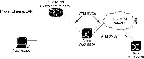
The workstation in Figure 10-1 uses a LAN to connect to a router that supports both LAN and ATM interfaces. An IP address is assigned to an ATM interface in each Cisco MGX 8850. To manage an MGX 8850, the workstation operator configures a network management program to communicate with the IP address assigned to the ATM interface. Network managers can use the following tools to manage the switch:
•
•
•
To support the ATM SVCs over which the IP traffic travels, both the router and switch are configured to map the respective IP addresses to ATM End Station Addresses (AESAs). When a management session is initiated, the IP workstation directs all communications to the IP address assigned to the ATM interface on the switch. The router encapsulates this IP traffic in ATM cells and forwards it over SVCs to the switch. The destination switch retrieves the IP messages from the ATM cells and forwards them to the internal IP management tools. Replies to the workstation follow the same path in reverse.
This feature provides maximum flexibility for switch management. Any workstation with a connection to a properly-configured ATM router can manage any switch in the network. Furthermore, additional routers connected to other switches can be configured to support this feature, enabling switch configuration from multiple locations throughout an ATM network.
Configuring the Switch
To support IP connectivity over the ATM interface, perform the following tasks:
•
•
•
•
To configure the switch to support IP connectivity to the ATM interface, use the following procedure.
Step 1
The default user name and password for this level are superuser, superuser.
Step 2
mgx8850a.7.PXM.a> dspipif atm0
Note
Step 3
If an IP address is configured, you can use that address. However, if the address has not been entered or is incompatible with your network, you must configure a valid IP address as described in the next step.
Step 4
mgx8850a.7.PXM.a> ipifconfig atm0 <IP_Addr> <netmask Mask>Replace IP_Addr with the IP address you want this port to use, and replace Mask with the network mask used on this network.
Tip
Note
Step 5
mgx8850a.7.PXM.a> dspipif atm0Step 6
Step 7
mgx8850a.7.PXM.a> svcifconfig atm0 local <ATM_Addr>Replace ATM_Addr with the AESA for the interface. This address must conform to the address plan for the switch.
Step 8
mgx8850a.7.PXM.a> svcifconfig atm0 router <ATM_Addr>Replace ATM_Addr with the AESA for the interface. This address must conform to the address plan for the switch.
Step 9
mgx8850a.7.PXM.a> dspsvcifStep 10
As described in "Configuring the PNNI Controller," in Chapter 2, "Configuring General Switch Features" in the Cisco MGX 8850Software Configuration Guide Release 2 .
Step 11
The line configuration should specify a UNI port, SCT 6, and a partition that supports at least 20 connections.
Step 12
The ATM addresses of directly attached ATM routers should appear in the list the switch displays. To display an ATM address for a remote router, you need to establish a CLI session on the remote switch and enter the dsppnsysaddr command.
Step 13
The following example shows commands that you can use to configure an Cisco MGX 8850 for IP communications over ATM.
Example 10-1 Switch Commands for IP Communications over ATM
mgx8850a.7.PXM.a> ipifconfig atm0 A.B.E.F # Replace A.B.E.F with IP Addressmgmgx8850a.7.PXM.a> svcifconfig atm0 local 47.0091.8100.0000.0010.7b65.f258.0010.7b65.1111.01mgx8850a.7.PXM.a> svcifconfig atm0 router 47.0091.8100.0000.0010.7b65.f258.0010.7b65.ffff.f1mgx8850a.7.PXM.a> addcontroller 2 i 2 7 #if controller does not already existmgx8850a.10.AXSM.a > cnfcdsct 6mgx8850a.10.AXSM.a > upln 1.1mgx8850a.10.AXSM.a > addport 1 1.1 96000 96000 6 1mgx8850a.10.AXSM.a > addpart 1 1 2 500000 500000 500000 500000 1 20 32 52 1 20mgx8850a.10.AXSM.a > upport 1mgx8850a.10.AXSM.a > cnfilmi -if 1 -id 1 -ilmi 1 -vpi 0 -vci 16 -trap 1 -s 10 -t 10 -k 10 #Optional. This command configures ILMI for the port.mgx8850a.7.PXM.a> addaddr 10:1.1:1 47.0091.8100.0000.0010.7b65.f258.0010.7b65. ffff.f1 160 #Enter only at switch with direct connection to router. Omit if using ILMI.mgx8850a.7.PXM.a> dsppnsysaddr(example output)47.0091.8100.0000.0010.7b65.f258.0010.7b65.ffff/152Type: uni Port id: 17111041mgx8850a.7.PXM.a> dsppnports(example output)Per-port status summaryPortId IF status Admin status ILMI state Total Activeconns10:1.1:1 up up Undefined 3Configuring the Router
To support IP over ATM communications on the ATM router, you need to configure the following interfaces:
•
•
To configure the ATM interface to the switch, you need to performs the following tasks:
•
•
•
•
If the router's IP address for the ATM interface is on the same subnet as the IP address on the switch ATM interface, no additional configuration is required for the router's IP LAN interface.
To configure the IP interface to the LAN, you need to perform the following tasks:
•
•
The procedure you use to configure the ATM router will depend on the router you are using. The following example lists commands you can use on a Cisco router to support IP over ATM communications with the Cisco MGX 8850.
Example 10-2 Router Configuration Commands for IP Communications over ATM
config termip routingip route 0.0.0.0 0.0.0.0 W.X.Y.Z 1 (set default route)interface atm 0ip address A.B.C.D G.H.I.J # G.H.I.J = netmaskatm nsap-address 47.0091.8100.0000.0010.7b65.f258.0010.7b65.ffff.f1atm uni-version 3.1atm pvc 1 0 5 qsaalatm pvc 2 0 16 ilmi #Optional. Enter to enable ILMI.atm ilmi-keepalive 10 #Optional. Enter to configure ILMI.atm esi-address 00107B65FFFF.F1 #Optional. Enter to support ILMI.atm arp-server selfno shut^Zwrite memorycnflan
Configure LAN
This command configures node communication parameters, so the node can communicate with a Cisco WAN Manager terminal over an Ethernet LAN using TCP/IP protocol. The parameters all contain address information about the Ethernet TCP/IP network that connects the Cisco WAN Manager station to an IGX or BPX node. The values must conform to those of the network. The network administrator can supply the parameters.
Syntax
cnflan <IP_Address> <IP_Subnet_Mask> <Maximum LAN Transmit Unit>
		<TCP Service Port><GatewayIPAddr>
Related Commands
upln, dnln, cnfln
Attributes
Example
sw197 TN SuperUser IGX 8420 9.2 Apr. 7 1998 01:48 GMTActive IP Address: 172.29.9.111IP Subnet Mask: 255.255.255.0IP Service Port: 5120Default Gateway IP Address: 172.29.9.1Maximum LAN Transmit Unit: 1500Ethernet Address: 00.C0.43.00.1F.7FType StateLAN READYTCP UNAVAILUDP READYTelnet READYTFTP READYTimeHdlr READYSNMP READYThis Command: cnflanEnter IP Address:cnfnwip
Configure Network IP Address
The network IP address and subnet mask support statistics collection for Cisco WAN Manager. The cnfnwip command defines the IP address the system uses to pass messages between Cisco WAN Manager and the node. The Statistics Master process in Cisco WAN Manager Network collects statistics. The Statistics Manager requests and receives statistics using TFTP Get and Put messages. These TFTP messages pass between the node and the Statistics Master using IP Relay. (See the cnfstatmast description for details on setting the Statistics Master address.)
Syntax
cnfnwip <IPAddr> <IPSubnetMask>
<IPAddr>
IP address of the node: the format is nnn.nnn.nnn.nnn, where nnn can be 1-255
<IPSubnetMask>
subnet mask: the format is nnn.nnn.nnn.nnn
Related Commands
None
Attributes
Example
cnfnwip 169.134.90.106 255.255.255.0axiom TN Bootzilla IGX 32 9.2 Aug. 5 19981998 18:25 GMTActive Network IP Address: 169.134.90.106Active Network IP Subnet Mask: 255.255.255.0Last Command: cnfnwip 169.134.90.106 255.255.255.0Next Command:cnfstatmast
Configure statistics master SV+ address
Configures an IP address for the Statistics Master process in WAN Manager. The cnfstatmast command defines the IP address for routing the messages to and from the Statistics Master in WAN Manager.
The Statistics Master process requests and receives network statistics by using TFTP Get and Put messages. These TFTP messages pass between the node and the Statistics Master over IP Relay. See the cnfnwip description for details on setting a node address.
Syntax
cnfstatmast <ip Address>
ip address
Specifies the IP address for the Statistics Master. IP addresses have 32-bits. The format of an IP address is x.x.x.x, where x is a value in the range 1-255.
Related Commands
cnfnwip, dspnwip
Attributes
Example
cnfstatmast 199.35.96.217
Configure 199.35.96.217 as the IP address for the Statistics Master.
Configuring PNNI using CiscoView
CiscoView provides the capability for configuring and displaying PNNI parameters on an MGX 8000 Series PXM 45 card.
Getting Started
Start the PNNI configuration by performing the following steps.
Step 1
Step 2
Step 3
Step 4
Step 5
Step 6
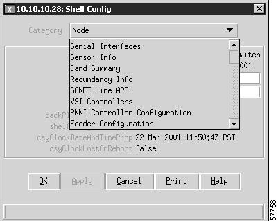
Step 7
Figure 10-2 Shelf Configuration Window Showing Category Dropdown Menu
PNNI Configuration
Continue the PNNI configuration by performing the following steps.
Step 1
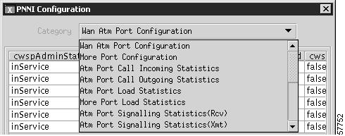
This window has a drop-down menu that permits the user to select from 18-PNNI configuration categories. Categories consist of configuration dialog boxes and display boxes as shown in Figure 10-3.
Figure 10-3 PNNI Configuration
Step 2
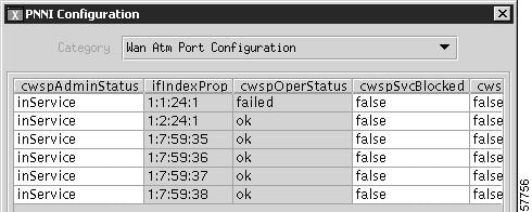
Each configuration dialog box consist of a table of parameter values associated with its category. Parameters that are configurable by the user have a white background and parameters that are for display only have a shaded background as shown in Figure 10-4.
Figure 10-4 Typical PNNI Configuration Dialog Box
Step 3
Figure 10-5 Row Creation Dialog Box
Step 4
PNNI Configuration Categories
Table 10-1 shows the parameters for each of the PNNI categories.
Note