
Table Of Contents
IP Reachability
This appendix addresses the issue of how CWM accesses the nodes in the network that it is managing. In particular this appendix describes how to the configure the communication method using the IP reachability field in the svplus/config/network.conf file.
Overview
CWM needs to communicate with the network nodes that are being managed to perform the following applications.
•
Network topology discovery (AutoRoute and PNNI)
•
•
•
For all these applications, CWM uses IP addresses to identify the destination node that is to receive a packet or message. However, depending upon the application and network equipment types, several IP addressing schemes are configurable by the user. These schemes are listed below.
•
–
–
–
•
–
–
For AutoRoute networks the scheme is selected by the value of the IP reachability field in the network.conf.
For PNNI networks, the default scheme uses the ILMI management PVCs provided by the ATM protocol. Alternatively, LANs can be used by configuring at the node level entering the CLI cnfndparms command.
General Guidelines
The following guidelines should be observed when configuring IP reachability
•
•
•
AutoRoute Networks
In AutoRoute networks IP reachabilty can be either in-band or out-of-band.
In-band—NWIP ON
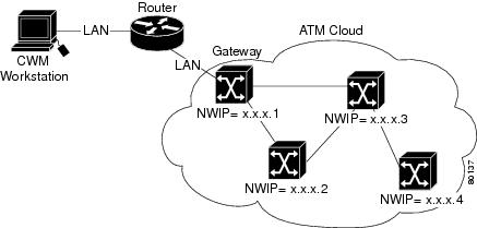
Figure B-1 shows an example of an AutoRoute network in which the communication method between CWM and the network nodes is in-band.
In this example there are four network nodes of which one is designated a gateway node. CWM communicates with the network through a LAN connection to the gateway node (via a router in this case). For CWM applications CWM uses the node's NWIP address for specifying the destination node of a message. The network nodes use a Cisco proprietary IP relay protocol whereby a node can examine the destination IP address, look it up in a routing table, and relay the message to the next hop. Although the network uses ATM to transmit cells across the network links, the network, in effect, performs as an IP level 3 routing network for CWM messages.
To use this method, the user enters NWIP ON as the value in the IP reachability field of the svplus/config/network.conf file.
Figure B-1 Example of AutoRoute In-band Communications
In-band—NWIP OFF
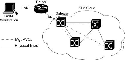
Figure B-2 shows an example of an AutoRoute network in which communication between CWM and the network nodes is in-band and uses PVCs set up by the gateway node.
In this example there are four-network nodes of which one is designated a gateway node. CWM communicates with the network through a LAN connection to the gateway node (via a router in this case). Unlike the NWIP-ON case, only the gateway node performs the routing function. The gateway node uses its AutoRoute topology knowledge to set up a dedicated PVC to each network node for the purpose of transmitting CWM messages. For CWM applications CWM uses the node's NWIP address for specifying the destination node of a message. When such a message is received by the gateway node, it looks up the PVC for the specified IP destination and uses the PVC to relay the message across the network to its destination.
To use this method, the user enters NWIP OFF as the value in the IP reachability field of the svplus/config/network.conf file.
Figure B-2 Example of AutoRoute Out-of-band Communications using PVCs
Out-of-band—LANIP
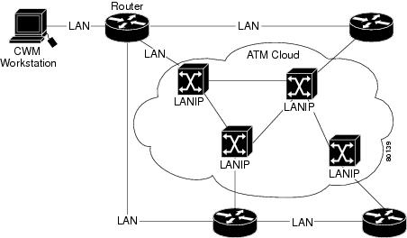
Figure B-3 shows an example of an AutoRoute network in which communication between CWM and the network nodes is out-of-band and uses PVCs set up by the gateway node.
In this example there are four network nodes where each is connected to CWM through a separate IP LAN (or LAN emulation network). In this case, no CWM messages are carried across the managed network. CWM communicates over the LAN using the node's LAN IP address as the destination address.
To use this method, the user enters LANIP as the value in the IP reachability field of the svplus/config/network.conf file.
Figure B-3 Example of AutoRoute Out-of-band Communications using LANs
PNNI Networks
For communication between CWM and PNNI nodes, CWM does not use the IP reachability field in the network.conf file. If present, both the IP_REACHABITY field and the OPTIONS field are ignored.
Instead, the method of CWM communication with a PNNI node depends upon the managed node's primary IP interface.
Option 8 in the configure node parameters (cnfndparms) command allows the user to set the node's primary IP address as follows.
•
•
•
CWM learns the primary IP interface by doing a MIB-walk and reading the PNNI topology state element table. By this means, CWM uses either the atm0 address or lnPci0 address to communicate with the node.
atm0 Method
This is the default method and uses ATM's ILMI (vpi = 0, vci = 16) facility and the neighbor routing protocol provided by PNNI. This method uses the node's IP address which is configured at the node using option 8 in the cnfndparms command and entering 0 (atm0).
lnPcio Method
Alternatively, CWM can use the out-of-band method using a separate LAN (or LAN emulation network) similar to that shown in Figure B-3. To enable this method, the user must configure each node using the option 8 in the cnfndparms command and entering 2 (lnPci0).