Replace Chassis Components


Note


The images in this chapter are only for representation purposes, unless specified otherwise. The chassis' actual appearance and size may vary.


Replace Fan Modules


Note


To know the fan tray serial number in case of NCS 5500 series fixed-port routers, you must check the label on the fan tray.


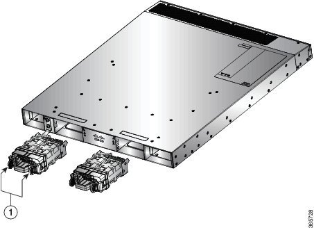
Replace NCS 55A1-24H, NCS 55A1-36H-S, NCS 55A1-36H-SE-S, NCS 5501,NCS 5501-SE, NCS-55A1-48Q6H, NCS-55A1-24Q6H-S and NCS-55A1-24Q6H-SS Fan Modules

The fan module is designed to be removed and replaced while the system is operating without presenting an electrical hazard or damage to the system, if the replacement is performed within 2 minutes.

Note


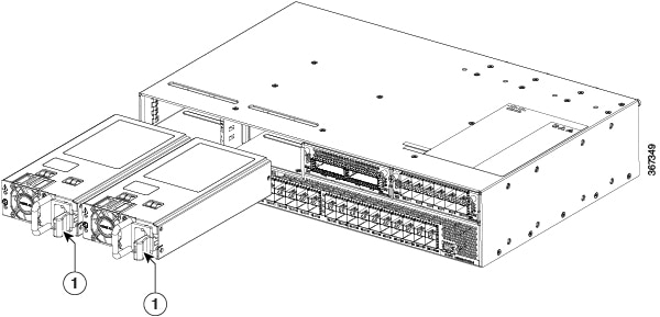
The NCS 5501 and NCS 5501-SE routers support NCS-1RU-FAN-FW (port-side intake airflow) and NCS-1RU-FAN-RV (port-side exhaust airflow) fan modules.

The NCS 55A1-24H, NCS 55A1-36H-S and NCS 55A1-36H-SE-S routers support NC55-A1-FAN-FW (port-side intake airflow) and NC55-A1-FAN-RV (port-side exhaust airflow) fan modules.

The NCS-55A1-48Q6H routers support NC55-A1-FAN-FW (port-side intake airflow) and NC55-A1-FAN-RV (port-side exhaust airflow) fan modules.

The NCS-55A1-24Q6H-S routers support NCS-1RU-FAN-FW (port-side intake airflow) and NCS-1RU-FAN-RV (port-side exhaust airflow) fan modules.

The NCS-55A1-24Q6H-SS routers support NCS-1RU-FAN-FW (port-side intake airflow) fan module.


Note


The airflow direction must be the same for all power supply and fan modules in the chassis.

Procedure


Step 1

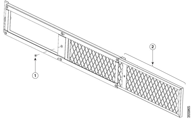
To remove a fan module, follow these steps:

  1. Press two latches on the fan module, grasp the handle of fan module.

    Note

     
    The following figure shows the NCS 5501-SE router. The procedure is the same for NCS 5501, NCS-55A1-48Q6H, NCS-55A1-24Q6H-S/NCS-55A1-24Q6H-SS and NCS 55A1 routers.
    Figure 1. Remove NCS 5501-SE Fans
  2. Simultaneously press the latches, and pull the fan module fully out of the chassis.

  3. Pull the fan module clear of the chassis.

Step 2

To install a fan module, follow these steps:

  1. Hold the fan module with the LED and PID label at the top.

  2. Align the fan module to the open fan tray slot in the chassis and press the module all the way into the slot until the left and right latches click and locked on the chassis.

    Note

     
    If the fan module does not go all the way into the slot, do not force it. Remove the fan module and verify that it is the correct type for your router and in the correct orientation.
  3. If the chassis is powered on, listen for the fans. You should immediately hear them operating. If you do not hear them, ensure that the fan module is inserted completely in the chassis.

  4. Verify that the fan module LED is green. If the LED is not green, one or more fans are faulty. If this situation occurs, contact your customer service representative for replacement parts.


Installing or Replacing the Latched Fan Module


Note


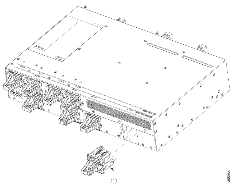
The Cisco NCS-55A2-MOD-HD-S, Cisco NCS-55A2-MOD-HX-S and Cisco NC55A2-MOD-SE-H-S routers support NC55-A2-FAN-L-FW (port-side intake airflow) fan modules.


This procedure replaces the NC55-A2-FAN-L-FW latched fan module in Cisco NCS-55A2-MOD-HD-S, Cisco NCS-55A2-MOD-HX-S and Cisco NC55A2-MOD-SE-H-S.

Procedure


Step 1

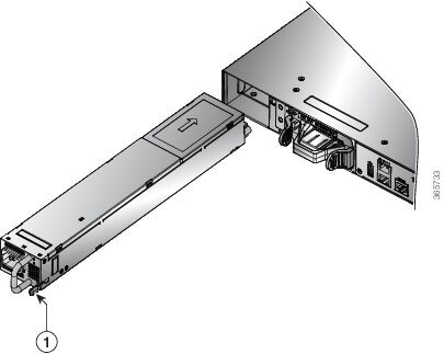
To insert the fan module (NC55-A2-FAN-L-FW) , do the following:

  1. Hold the fan module with the LED and PID label at the top.

  2. Align the fan module in the right orientation to the open fan tray slot in the chassis.

    Note


    If the fan module does not go all the way into the slot, do not force it. Remove the fan module and verify that it is the correct type for your chassis and in the correct orientation.

  3. Push the module all the way into the slot until the latches click and lock into the chassis.

  4. If the chassis is powered on, listen for the fans. You should immediately hear them operating. If you do not hear them, ensure that the fan module is inserted completely in the chassis.

  5. Verify that the fan module LED is green. If the LED is not green, one or more fans are faulty. If this situation occurs, contact your customer service representative for replacement parts.

Step 2

To remove the fan module, do the following:

  1. Press both the latches on the fan module to disengage the fan module connection from the chassis.

  2. Simultaneously press the latches, and pull the fan module fully out of the chassis.

  3. Pull the fan module clear of the chassis.

    Note


    The fan module port assignment label is present at the rear-top surface of the chassis.

    Figure 2. Replace the Latched Fan Module

    1

    Fan Module

Replace NCS 55A2-MOD-S, NCS 55A2-MOD-SE-S, NCS-55A2-MOD-HX-S, NC55A2-MOD-SE-H-S, NCS 55A2-MOD-HD-S, NCS 5502, NCS 5502 SE Fan Modules

Cisco NCS 55A2-MOD-S, NCS 55A2-MOD-SE-S, NCS-55A2-MOD-HX-S,NC55A2-MOD-SE-H-S,NCS 55A2-MOD-HD-S, NCS 5502 and NCS 5502 SE routers have fan redundancy protection mechanism against a single fan failure. If a fan fails, these can work for unlimited time without any performance degrade. When the failed fan is replaced, the new fan must be physically placed within 3 minutes.


Note


The NCS 55A2-MOD-S, NCS 55A2-MOD-SE-S, NCS-55A2-MOD-HX-S, NC55A2-MOD-SE-H-S and NCS 55A2-MOD-HD-S routers have 8 fans: 4 fans for the MPAs (top) and 4 fans for the chassis baseboard (bottom). The top and bottom levels can operate with a minimum of 3 fans each.

Procedure


Step 1

Unscrew the thumbscrew on the fan.
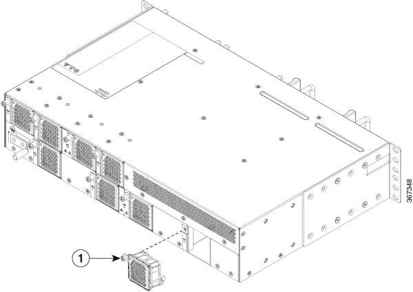
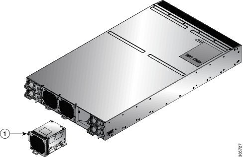
Figure 3. Remove NCS 55A2-MOD-S , NCS 55A2-MOD-SE-S, NCS-55A2-MOD-HX-S, NC55A2-MOD-SE-H-S and NCS 55A2-MOD-HD-S Fan Modules
Figure 4. Remove NCS 5502 and NCS 5502 SE Fan Modules

1

Fan module thumbscrew

Step 2

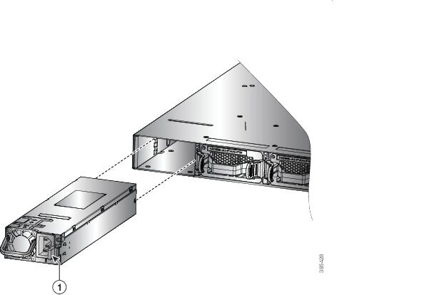
Pull the handle to remove the fan to be replaced.

Step 3

Hold the fan module with the LED and PID label at the top.

Step 4

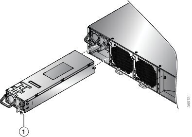
Align the fan module to the open fan slot in the chassis and press the module all the way into the slot until the front of the fan module touches the chassis.

Make sure that the thumbscrew on the fan module is aligned with the screw hole in the chassis.

Step 5

Tighten the thumbscrew to secure the fan module in the chassis.

Step 6

If the chassis is powered on, listen for the fans. You should immediately hear them operating. If you do not hear them, ensure that the fan module is inserted completely in the chassis.

Step 7

Verify that the fan module LED is green. If the LED is not green, one or more fans are faulty. If this situation occurs, contact your customer service representative for replacement parts.


Replacing the Air Filter Frame

This procedure replaces the air filter frame (NCS-55A2-FLTR-FW) in Cisco NCS-55A2-MOD-HD-S, Cisco NCS-55A2-MOD-HX-S and Cisco NC55A2-MOD-SE-H-S.


Note


A periodic health check of the filter, every three months based on the level of dust in the environment, helps in avoiding over clogging of the filters and provide a better life. This product's filter is used as a single-use component. If the product is installed in a controlled environment, check and replace the filter every three months, otherwise replace the filter every month.

Procedure


Step 1

Remove the counter sink M3 screw on the filter faceplate with a torque value of 5 in-lbs (.56 N-m).

Step 2

Remove the filter frame from the right side as shown in the following figure.

Figure 5. Replace the Air Filter Frame

1

Screw

2

Air Filter Frame

Step 3

Slide the new filter frame in the reverse direction and tighten the counter sink M3 screw with a torque value of 5 in-lbs (.56 N-m).


Replace Power Supply

Use this procedure to replace the AC or DC power supply units.

Procedure


Step 1

If the power supply is connected to a DC circuit, shut off the circuit at the circuit breaker.

Step 2

Disconnect the PSU cable.

Step 3

Press the tab inward to unlatch the PSU, then pull the handle to remove the PSU.

Step 4

To install the new PSU, press the tab inward and then insert the PSU.

Note

 
If the PSU does not go all the way into the slot, do not force it. Remove the PSU and verify that it is the correct type for your router and in the correct orientation.

Step 5

Connect the PSU cable.

Step 6

If the power supply is connected to a DC circuit, turn on the circuit breaker for the DC power source.

Note

 
The following figure shows the NCS 5501 router. The procedure is the same for the NCS 5501-SE, NCS-55A1-48Q6H, NCS-55A1-24Q6H-S/NCS-55A1-24Q6H-SS, and NCS 55A1-24H router.
Figure 6. Remove NCS 5501 Power Supply
Figure 7. Remove NCS 55A1-36H-S and NCS 55A1-36H-SE-S Power Supply
Figure 8. Remove NCS 5502 and NCS 5502 SE Power Supply
Figure 9. Remove NCS 55A2-MOD-S, NCS 55A2-MOD-SE-S , NCS-55A2-MOD-HX-S,NC55A2-MOD-SE-H-S,and NCS 55A2-MOD-HD-S Power Supply

1

Tab