NCS 5500 Series Fixed-Port Router Overview

NCS 5500 Series Fixed-Port Routers

The Cisco NCS 5500 series fixed-port routers include:


Note


To determine which transceivers and cables are supported by these routers, see Cisco Transceiver Modules Compatibility Information.
  • NCS-5501: Fixed port, high density, one rack unit form-factor router that supports port density of 48 x SFP/SFP+ ports, each capable of supporting one Gigabit Ethernet or 10 Gigabit Ethernet and 6 x QSFP+/QSFP28 ports, each capable of supporting 10 Gigabit Ethernet (via cable breakout), 40 Gigabit Ethernet or 100 Gigabit Ethernet transceivers.

  • NCS-5501-SE: Fixed port, high density, one rack unit form-factor router that supports 40 x SFP/SFP+ ports, each capable of supporting one Gigabit Ethernet or 10 Gigabit Ethernet and 4 x QSFP+/QSFP28 ports each, capable of supporting 10 Gigabit Ethernet (via cable breakout), 40 Gigabit Ethernet, or 100 Gigabit Ethernet transceivers. The router can support 24 x DWDM SFP+ ports. The router has additional TCAM to support large prefix scale.

  • NCS-55A1-48Q6H: Fixed port, high density, one rack unit form-factor router that supports 48 x SFP/SFP+/SFP28G ports, each capable of supporting one Gigabit Ethernet or 10 Gigabit Ethernet or 25 Gigabit Ethernet and 6 x QSFP+/QSFP28 ports each, capable of supporting 10/25 Gigabit Ethernet (via cable breakout), 40 Gigabit Ethernet, or 100 Gigabit Ethernet transceivers.

  • NCS-55A1-24Q6H-S: Fixed port, high density, one rack unit form-factor router that supports 48 x SFP/SFP+ ports, each capable of supporting one Gigabit Ethernet or 10 Gigabit Ethernet. Out of these 48 ports, last 24 ports support 25 Gigabit Ethernet. It also has 6 x QSFP+/QSFP28 ports each, capable of supporting 10/25 Gigabit Ethernet (via cable breakout), 40 Gigabit Ethernet, or 100 Gigabit Ethernet transceivers.

  • NCS-55A1-24Q6H-SS: Fixed port, high density, one rack unit form-factor router that supports 48 x SFP/SFP+ ports, each capable of supporting one Gigabit Ethernet or 10 Gigabit Ethernet. Out of these 48 ports, last 24 ports support 25 Gigabit Ethernet. It also has 6 x QSFP+/QSFP28 ports each, capable of supporting 10/25 Gigabit Ethernet (via cable breakout), 40 Gigabit Ethernet, or 100 Gigabit Ethernet transceivers. All the ports are MACSec enabled. This chassis supports only port side intake installation configuration. Also, MACSec cannot be enabled if the rate of data transmission is 1 G.

  • NCS-55A1-36H-S: Fixed port, high density, one rack unit form-factor router that supports port density of 36 x QSFP ports, each capable of supporting 10 GE (via cable breakout), 25 GE (via cable breakout), 40 GE (QSFP+), or 100 GE (QSFP28) transceivers. The router also supports the QSFP-to-SFP adapter (QSA) with 10 GE SFP+ (SR, SR-S, LR, and LR-S).

  • NCS-55A1-36H-SE-S: Fixed port, high density, one rack unit form-factor router that supports port density of 36 x QSFP ports, each capable of supporting 10 GE (via cable breakout), 25 GE (via cable breakout), 40 GE (QSFP+), or 100 GE (QSFP28) transceivers. The router also supports the QSFP-to-SFP adapter (QSA) with 10 GE SFP+ (SR, SR-S, LR, and LR-S). The router has additional TCAM to support large prefix scale.

  • NCS-55A1-24H: Fixed port, high density, one rack unit form-factor router that supports port density of 24 x QSFP ports, each capable of supporting 10 GE (via cable breakout), 25 GE (via cable breakout), 50 GE (via cable breakout), 40 GE (QSFP+), or 100 GE (QSFP28) transceivers. The router also supports the QSFP-to-SFP adapter (QSA) with 1GE SFP (GLC-SX-MMD, GLC-LH-SMD) and 10 GE SFP+ (SR, SR-S, LR, and LR-S).

  • NCS-5502: Fixed port, high density, two rack unit form-factor router that supports 48 QSFP ports, each of which is capable of supporting 10 GE (via cable breakout), 40 GE, or 100 GE transceivers. The router also supports the QSFP-to-SFP adapter (QSA) with 10 GE SFP+ (SR, SR-S, LR, and LR-S).

  • NCS-5502-SE: Fixed port, high density, two rack unit form-factor router that supports 48 QSFP ports, each of which is capable of supporting 10 GE (via cable breakout), 40 GE, or 100 GE transceivers. The router has additional TCAM to support large prefix scale. The router also supports the QSFP-to-SFP adapter (QSA) with 10 GE SFP+ (SR, SR-S, LR, and LR-S).

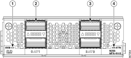
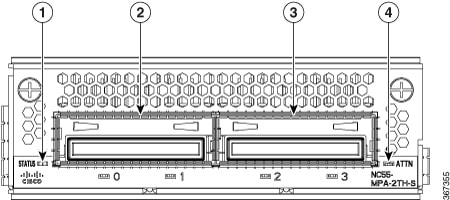
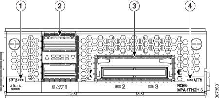
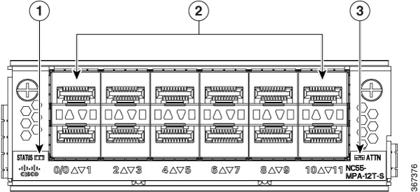
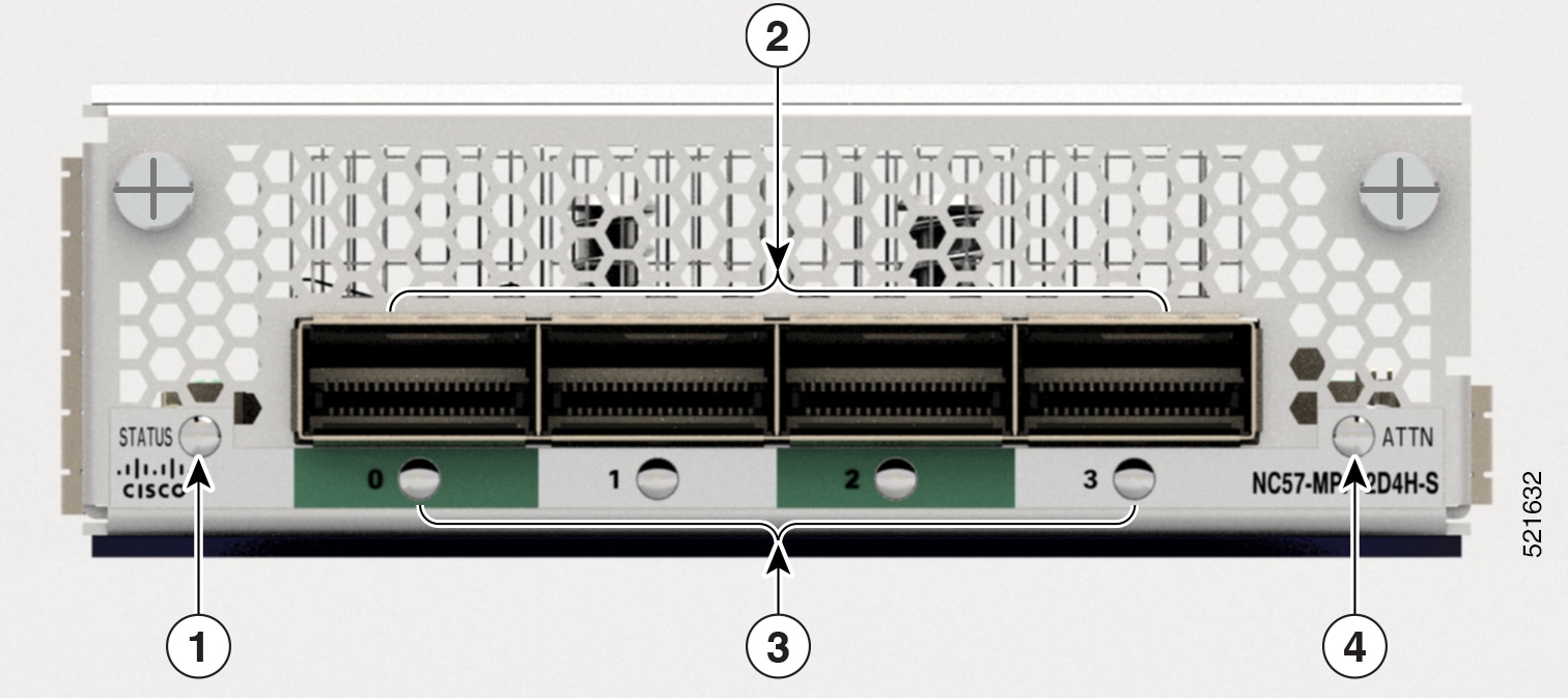
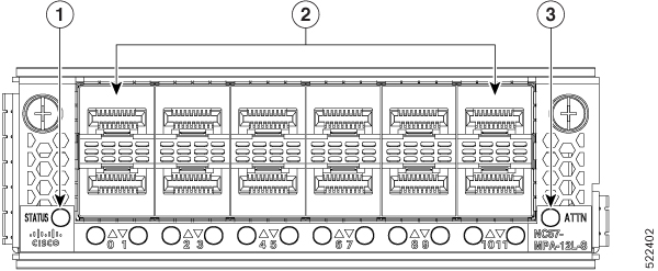
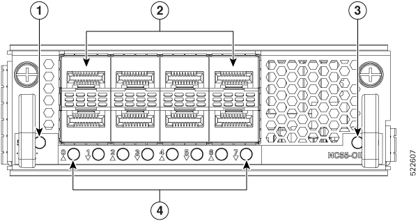
  • NCS-55A2-MOD-S: Fixed port, high density, two rack unit form-factor router that supports 24 SFP/SFP+ ports capable of supporting one Gigabit Ethernet or 10 Gigabit Ethernet, and 16 SFP/SFP+/SFP28 ports capable of supporting one Gigabit Ethernet, 10 Gigabit Ethernet, or 25 Gigabit Ethernet. The router also supports up to 2 modular port adapters (MPA). See the Modular Port Adapters section.

  • NCS-55A2-MOD-HD-S: Temperature-hardened, fixed port, high density, two rack unit form-factor router that supports 24 SFP/SFP+ ports capable of supporting one Gigabit Ethernet or 10 Gigabit Ethernet, and 16 SFP/SFP+/SFP28 ports capable of supporting one Gigabit Ethernet, 10 Gigabit Ethernet, or 25 Gigabit Ethernet. The router also supports up to 2 modular port adapters (MPA). See the Modular Port Adapters section.


    Note


    If you install commercial-temperature MPAs in the NCS-55A2-MOD-HD-S router, the router will operate within the commercial-temperature specifications.
  • NCS-55A2-MOD-SE-S: Fixed port, high density, two rack unit form-factor router that supports 24 SFP/SFP+ ports capable of supporting one Gigabit Ethernet or 10 Gigabit Ethernet, and 16 SFP/SFP+/SFP28 ports capable of supporting one Gigabit Ethernet, 10 Gigabit Ethernet, or 25 Gigabit Ethernet. The router also supports up to 2 modular port adapters (MPA). See the Modular Port Adapters section. The router has external TCAM to support expanded Forwarding Information Base (FIB), network Access Control Lists (ACLs), and QoS for scale-enhanced configuration needs.

  • NCS-55A2-MOD-HX-S: Temperature-hardened, conformal coated, fixed port, high density, two rack unit form-factor router that supports 24 SFP/SFP+ ports capable of supporting one Gigabit Ethernet or 10 Gigabit Ethernet, and 16 SFP/SFP+/SFP28 ports capable of supporting one Gigabit Ethernet, 10 Gigabit Ethernet, or 25 Gigabit Ethernet. The router also supports up to 2 modular port adapters (MPA). See the Modular Port Adapters section.

  • NC55A2-MOD-SE-H-S: Temperature-hardened, conformal coated, fixed port, high density, two rack unit form-factor router that supports 24 SFP/SFP+ ports capable of supporting one Gigabit Ethernet or 10 Gigabit Ethernet, and 16 SFP/SFP+/SFP28 ports capable of supporting one Gigabit Ethernet, 10 Gigabit Ethernet, or 25 Gigabit Ethernet. The router also supports up to 2 modular port adapters (MPA). See the Modular Port Adapters section. The router has external TCAM to support expanded Forwarding Information Base (FIB), network Access Control Lists (ACLs), and QoS for scale-enhanced configuration needs.


Note


To determine which transceivers and cables are supported by these routers, see Cisco Transceiver Modules Compatibility Information.

Note


The following fixed-port routers support configuration of four ports using one quad CLI, hw-module quad :

  • NCS-55A1-48Q6H

  • NCS-55A1-24Q6H-S

  • NCS-55A1-24Q6H-SS

  • NCS-55A2-MOD-S

  • NCS-55A2-MOD-SE

  • NCS-55A2-HD-MOD-S

  • NCS-55A2-MOD-HX-S

  • NC55A2-MOD-SE-H-S


Note


We recommend to change the offset value of the conf-offset <offset_value> command (MACsec encryption command) in Cisco NCS 5500 fixed port routers only when the port is in admin down state (that is, when the interface is shut down). Changing the offset value otherwise may result in traffic loss.

Modular Port Adapters

The modular port adapters (MPAs) are supported in the NCS-55A2-MOD-S, NCS-55A2-MOD-SE-S, NCS-55A2-MOD-HX-S,NC55A2-MOD-SE-H-S, and NCS-55A2-MOD-HD-S routers. Each MPA has a STATUS and ATTN (attention) LED, and each port on the MPA has an adjacent A/L (Active/Link) LED.

To determine which transceivers and cables are supported by these MPAs, see Cisco Transceiver Modules Compatibility Information.


Note


Before replacing an MPA card remove the port-range configurations that are applied on that MPA. If these configurations are not removed, interfaces in the new MPA card are not available.


Note


In Cisco NCS-55A2 routers, if the MPA ejectors are exposed to contaminants from the environment or other sources, the system will issue an ejector open alarm and shut down the MPA, even if the ejector is closed. From Release 25.3.1 onwards, in order to prevent the MPA from shutting down unexpectedly, execute the “hw-module subslot {all|location-id} ejector-disable” command. If you disable the MPA ejector function using this command, make sure to use the Managed OIR procedure when removing the MPA.


4-Port 40GE/100GE MPA with QSFP+/QSFP28

The 4-port 40GE/100GE MPA (NC55-MPA-4H-S/NC55-MPA-4H-HD-S/NC55-MPA-4H-HX-S) provides 4 ports for 4x25GE (via cable breakout), QSFP+ (40Gbps) or QSFP28 (100Gbps) transceivers.


Note


The temperature-hardened NC55-MPA-4H-HD-S MPA operates within industrial temperature range when installed in the temperature-hardened routers.

Note


The temperature-hardened conformal-coated NC55-MPA-4H-HX-S MPA operates within industrial temperature range when installed in the temperature-hardened routers.


1

STATUS LED

3

QSFP port and Active/Link LED

2

QSFP port and Active/Link LED

4

ATTN LED

2-Port 100GE/200GE with CFP2-DCO

The 2-port 100GE/200GE MPA (NC55-MPA-2TH-S/NC55-MPA-2TH-HX-S) provides 2 ports for CFP2-DCO transceivers.


Note


The temperature-hardened conformal-coated NC55-MPA-2TH-HX-S MPA operates within industrial temperature range when installed in the temperature-hardened routers.


1

STATUS LED

3

CFP2-DCO port and Active/Link LED

2

CFP2-DCO port and Active/Link LED

4

ATTN LED

1-port 100GE/200GE with CFP2-DCO + 2-Port 40GE or 100GE with QSFP+/QSFP28

The 1-port 100GE/200GE + 2-Port 40GE/100GE combination MPA (NC55-MPA-1TH2H-S) provides 1 port for CFP2-DCO transceivers and 2 ports for 4x25GE (via cable breakout), QSFP+ (40Gbps) or QSFP28 (100Gbps) transceivers.

1

STATUS LED

3

CFP2-DCO port and Active/Link LED

2

QSFP port and Active/Link LED

4

ATTN LED

12-Port 10GE with SFP+

The 12-port 10GE MPA (NC55-MPA-12T-S) provides 12 ports for SFP+ transceivers.

1

STATUS LED

3

ATTN LED

2

SFP+ ports and LEDs


Note


The NCS-57C3 routers support 12-port 10GE MPA (NC55-MPA-12T-S); however, MPA slots 2 and 3 do not support 1G interfaces. On slot 1, ports 0-3 and 8-11 only support 1G. MACSec is not supported on these 1G interfaces.


4-Port 800GE MPA with QSFP28/QSFP-DD

Table 1. Feature History Table

Hardware

Release Information

Description

NC57-MPA-2D4H-S modular port adapter

Release 7.4.1

This release introduces a 4-port 800GE modular port adapter (NC57-MPA-2D4H-S) that supports QSFP28 and QSFP-DD optical transceivers. This MPA is supported in the NCS-55A2-MOD and NCS-57C3-MOD routers. This is the first modular port adapter to support the QSFP-DD optical transceiver.

The NC57-MPA-2D4H-S modular port adapter supports QSFP28 and QSFP-DD optical transceivers in the following configurations:

  • Only one QDD-400GE transceiver is supported through port 0 in both the MPA slots of the NCS-55A2-MOD-HD-S, NC55-55A2-MOD-SE-S, NCS-55A2-MOD-S, or NCS-55A2-MOD-HX-S chassis.

The NC57-MPA-2D4H-S modular port adapter supports the following configurations of optical transceivers while operating on NC55-MOD-A-SE-S and NC57-MOD-S line cards.

Transceiver

MPA slot 1

MPA slot 2

  • Max bandwidth on NC55-MOD-A-SE-S line card = 400GE

  • Max bandwidth on NC57-MOD-S line card = 800GE

  • Max bandwidth on NC55-MOD-A-SE-S line card = 400GE

  • Max bandwidth on NC57-MOD-S line card = 800GE

QSFP28-100GE All ports All ports
QDD-2x100GE
  • On NC55-MOD-A-SE-S line card - Ports 0 and 2

    Note

     
    When QDD-2x100GE transceivers are installed in ports 0 and 2, then ports 1 and 3 cannot be used.
  • On NC57-MOD-S line card - All ports

  • On NC55-MOD-A-SE-S line card - Ports 0 and 2

    Note

     
    When QDD-2x100GE transceivers are installed in ports 0 and 2, then ports 1 and 3 cannot be used.
  • On NC57-MOD-S line card - All ports

QDD-3x100GE

  • On NC55-MOD-A-SE-S line card - Port 0

    Note

     
    When QDD-3x100GE transceivers are installed in port 0, then ports 1, 2 and 3 cannot be used.
  • On NC57-MOD-S line card - Ports 0 and 2

    Note

     
    When QDD-3x100GE transceivers are installed in ports 0 and 2, then ports 1 and 3 cannot be used.
QDD-400GE
  • On NC55-MOD-A-SE-S line card - Not supported

  • On NC57-MOD-S line card - Ports 0 and 2

    Note

     
    When QDD-400GE transceivers are installed in ports 0 and 2, then ports 1 and 3 cannot be used.
  • On NC55-MOD-A-SE-S line card - Not supported

  • On NC57-MOD-S line card - Ports 0 and 2

    Note

     
    When QDD-400GE transceivers are installed in ports 0 and 2, then ports 1 and 3 cannot be used.
QDD-4x100GE
  • On NC55-MOD-A-SE-S line card - Port 0

    Note

     
    When QDD-4x100GE transceivers are installed in port 0, then ports 1, 2 and 3 cannot be used.
  • On NC57-MOD-S line card - Ports 0 and 2

    Note

     
    When QDD-4x100GE transceivers are installed in ports 0 and 2, then ports 1 and 3 cannot be used.
Figure 1. NC57-MPA-2D4H-S Modular Port Adapter (MPA)

1

STATUS LED

3

Active/Link LED

2

QSFP28/QSFP-DD port and LED

4

ATTN LED

12-Port 10GE/25GE/50GE MPA with SFP+/SFP28/SFP56

Table 2. Feature History Table

Hardware

Release Information

Feature Description

NCS57-MPA-12L-S modular port adapter

Release 7.6.1

A 12-port 600GE modular port adapter that supports SFP+, SPF28, and SFP56 optical transceivers, the NCS57-MPA-12L-S operates in 10GE, 25GE, and 50GE modes.

The following command is modified to add support for the 50GE mode for even-numbered ports (port 4, port 6, port 8, and port 10):

For more information, see the Cisco Network Convergence System 5700 Series: Modular Port Adapters Data Sheet.

The NCS57-MPA-12L-S modular port adapter supports SFP+, SFP28 and SFP56 optical transceivers in these configurations:

Table 3. Supported SFP optical transceiver configurations

Port

MPA in NCS-55A2-MOD-SE-S

Maximum bandwidth per MPA = 400GE

0 and 1

  • 10G using hw-module quad command

  • 25G

  • 50G

  • Combination of 25G and 50G

Note


Combination of 10G with 25G or 50G is not supported.

2 and 3

4, 5, 6 and 7

  • 10G using hw-module quad command

  • 25G

  • Combination of 25G and 50G

Note


50G can be enabled on even-numbered ports using hw-module port-range and the subsequent odd port will be disabled.

Note


Combination of 10G with 25G or 50G is not supported.

8, 9, 10 and 11

Figure 2. NCS57-MPA-12L-S Modular Port Adapter (MPA)

1

STATUS LED

3

ATTN LED

2

SFP56 ports and LEDs

8-Port MPA with SFP+

Table 4. Feature History Table

Hardware

Release Information

Description

NC55-OIP-02 Modular Port Adapter

Release 7.7.1

An 8-port MPA (NC55-OIP-02) that supports SFP+ optical transceivers, this MPA is available for the NC55A2-MOD-S and NC57C3-MOD-SYS routers. It supports the following port mode options:

  • Ethernet

  • FC

  • OTN

  • SDH

  • SONET

The port-mode command is introduced to configure port mode option.

For more information on PLE, see Private Line Emulation over EVPN-VPWS Single Homed section of the L2VPN and Ethernet Services Configuration Guide for Cisco NCS 5500 Series Routers, IOS XR Release 7.7.x.

For more information on the MPA, see the Cisco Network Convergence System 5700 Series: Modular Port Adapters Data Sheet.

The NC55-OIP-02 modular port adapter supports SFP+ optical transceivers. The MPA supports the following port mode options:

  • Ethernet - 1GbE and 10GbE

  • Fiber channel (FC) - 1G, 2G, 4G, 8G, 16G, and 32G

  • Optical Transport Network (OTN) - OTU2 and OTU2e

  • Synchronous Digital Hierarchy (SDH) - STM16 and STM64

  • SONET - OC48 and OC192


Note


The NC55-OIP-02 supports circuit emulation (CEM) and does not support L3 VPN service termination.


The MPA supports the following data rates:

Table 5. Port mode data rate options
Port mode Data rate

1GbE

1.25 Gbps

10GbE

10.3125 Gbps

OC48

2.48832 Gbps

OC192

9.95328 Gbps

OTU2

10.709 Gbps

OTU2e

11.0957 Gbps

STM16

2.48 Gbps

STM64

9.95 Gbps

FC1

1.0625 Gbps

FC2

2.125 Gbps

FC4

4.25 Gbps

FC8

8.5 Gbps

FC16

14.025 Gbps

FC32

28.05 Gbps


Note


Port mode FC32 is supported only on the even ports (Port 0, 2, 4, and 6) of the MPA.


Figure 3. NC55-OIP-02 Modular Port Adapter (MPA)

1

STATUS LED

3

ATTN LED

2

SFP+ port

4

Active/Link LED

GNSS Port

The routers that support GNSS receiver are:

  • NCS-55A2-MOD-S

  • NCS-55A2-MOD-HD-S

  • NCS-55A2-MOD-HX-S

  • NCS-55A2-MOD-SE-S

  • NCS-55A1-48Q6H

  • NCS-55A1-24Q6H-S

  • NCS-55A1-24Q6H-SS

The built-in Global Navigation Satellite System (GNSS) port enables the router to determine its own location and get an accurate time from satellites.

GNSS Port RF Input Requirements

  • The GNSS port requires an active GPS/GNSS antenna with built-in Low-Noise Amplifier (LNA) for optimal performance. The antenna LNA amplifies the received satellite signals for two purposes:

    • Compensation of losses on the cable

    • Lifting the signal amplitude in the suitable range for the receiver frontend

The Amplification required is 22dB gain + cable/connector loss + Splitter signal loss.

The recommended range of LNA gain (LNA gain minus all cable and connector losses) at the connector of the receiver module is 22dB to 30dB with a minimum of 20dB and a maximum of 35dB.

  • GNSS port provides 5V to the active antenna through the same RF input.

  • Surge requirement:

    • GNSS port has built-in ESD protections on all pins, including the RF-input pin. However, additional surge protection may be required if rooftop antennas are being connected, to meet the regulations and standards for lightning protection in the countries where the end-product is installed.

    • A lightning protection must be mounted at the place where the antenna cable enters the building. The primary lightning protection must be capable of conducting all potentially dangerous electrical energy to PE (Protective Earth).

    • Surge arrestors should support DC-pass and suitable for the GPS frequency range (1.575GHz) with low attenuation.

  • Antenna Sky visibility:

    • GPS signals can only be received on a direct line of sight between antenna and satellite. The antenna must have a clear view of the sky. For proper timing, minimum of four satellites should be locked.


      Note


      The antenna terminal should be earthed at the building entrance in accordance with the ANSI/NFPA 70, the National Electrical Code (NEC), in particular Section 820.93, Grounding of Outer Conductive Shield of a Coaxial Cable.


    • Use a passive splitter if more than one GNSS ports are fed from a single antenna.


      Note


      The splitter should have all the RF ports capable of DC-pass, if the antenna needs to feed power from GNSS module.


External Alarm Inputs

The router supports four dry contact alarm inputs through an RJ-45 jack on the front panel. The alarm port is present on the following routers:

  • NCS-55A2-MOD-HD-S

  • NCS-55A2-MOD-HX-S

  • NC55A2-MOD-SE-H-S

It is normally in Open state to indicate that no current flows through the alarm circuit and the alarm is generated when the current is flowing.

Each alarm input can be provisioned as critical, major, or minor.