Connect Router to the Network

Port Connection Guidelines

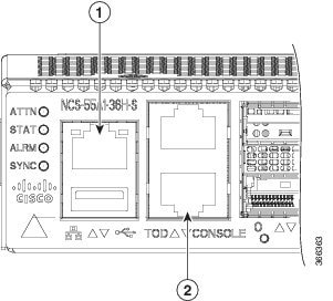
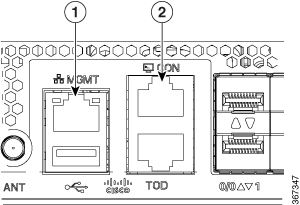
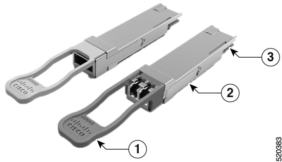
Depending on the chassis and installed line cards, you can use Quad Small Form-Factor Pluggable Plus (QSFP+), QSFP28, QSFP-DD, SFP, SFP+, CFP-DCO, and RJ-45 connectors to connect the ports on the line cards to other network devices.

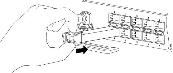
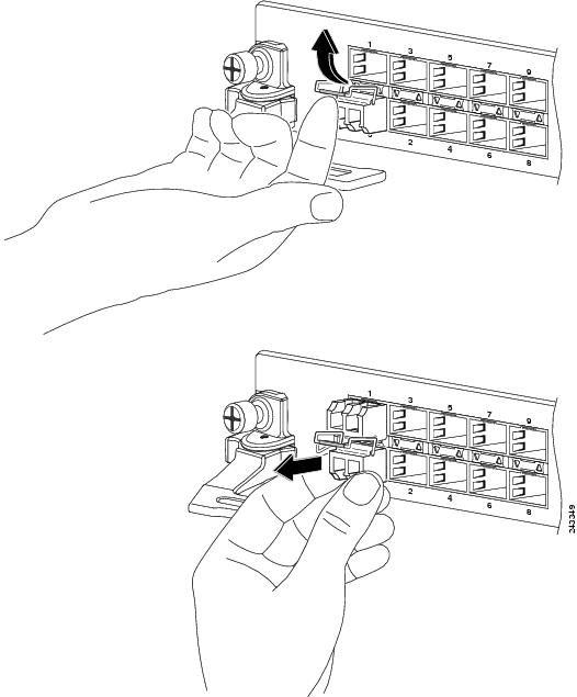
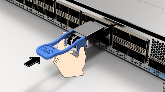
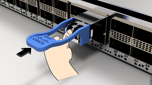
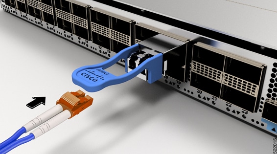
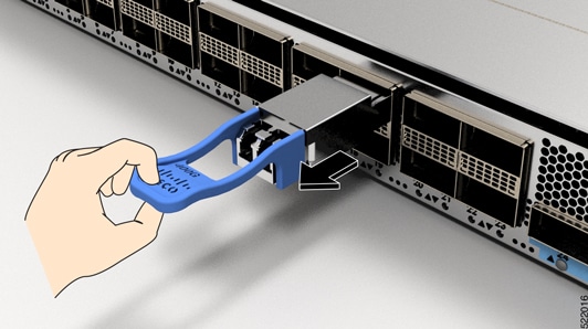
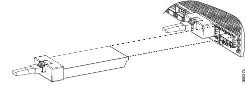
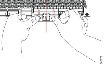
To prevent damage to the fiber-optic cables when installing a transceiver in the line card, we recommend that you disconnect the transceiver from its fiber-optic cables. Before removing the transceiver from the router, remove the cable from the transceiver. You can change or remove the cable without removing the transceiver.

To maximize the effectiveness and life of your transceivers and optical cables, do the following:

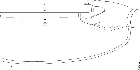
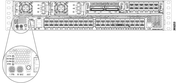
  • Wear an ESD-preventative wrist strap that is connected to an earth ground whenever handling transceivers. The router is typically grounded during installation and provides an ESD port to which you can connect your wrist strap.

  • Do not remove and insert a transceiver more often than is necessary. Repeated removals and insertions can shorten its useful life.

  • Keep the transceivers and fiber-optic cables clean and dust free to maintain high signal accuracy and to prevent damage to the connectors. Attenuation (loss of light) is increased by contamination and should be kept below 0.35 dB.

    • Clean these parts before installation to prevent dust from scratching the fiber-optic cable ends.

    • Clean the connectors regularly; the required frequency of cleaning depends upon the environment. In addition, clean connectors when they are exposed to dust or accidentally touched. Both wet and dry cleaning techniques can be effective; refer to your site's fiber-optic connection cleaning procedures.

    • Do not touch the ends of connectors. Touching the ends can leave fingerprints and cause other contamination.

  • Inspect routinely for dust and damage. If you suspect damage, clean and then inspect fiber ends under a microscope to determine if damage has occurred.


Warning


Statement 1051—Laser Radiation

Invisible laser radiation may be emitted from disconnected fibers or connectors. Do not stare into beams or view directly with optical instruments.


Connect to the Console Port

Before you create a network management connection for the router or connect the router to the network, you must create a local management connection through a console terminal and configure an IP address for the router. You also can use the console to perform the following functions (each of which can be performed through the management interface after you make that connection):

  • Configure the router using the command-line interface (CLI).

  • Monitor network statistics and errors.

  • Configure Simple Network Management Protocol (SNMP) agent parameters.

  • Download software updates.

The system console port is an RJ-45 receptacle for connecting a data terminal to perform the initial configuration of NCS 5500 fixed-port chassis. The console cable is shipped with the hardware.

Figure 1. NCS 55A1
Figure 2. NCS 55A2
Figure 3. NCS-55A1-48Q6H and NCS-55A1-24Q6H-S/ NCS-55A1-24Q6H-SS

1

Management Ethernet port

2

Console port

3

Time of Day (ToD) port

Follow this procedure to connect a data terminal to the console port.

Before you begin

  • The router must be fully installed in its rack, connected to a power source, and grounded.

  • The necessary cabling for the console, management, and network connections must be available.

    • An RJ-45 rollover cable and DB9F/RJ-45 adapter are provided in the router accessory kit.

    • Network cabling should already be routed to the location of the installed router.

Procedure


Step 1

Set your terminal to these operational values: 115200 bps, 8 data bits, no parity, 1 stop bits (115200 8N1).

Step 2

Attach the terminal end of the cable to the interface port on the data terminal.

Step 3

Attach the other end of the cable to the console port.


Table 1. RJ-45 Straight-through Cable Pin-outs

RJ-45 Pin

Signal

1

2

3

Tx

4

Ground (GND)

5

GND

6

Rx

7

8

Create the Initial Router Configuration

You must assign an IP address to the router management interface so that you can then connect the router to the network.

When you initially power up the router, it boots up and asks a series of questions to help configure the router. To enable you to connect the router to the network, you can use the default choices for each configuration except for the IP address, which you must provide.


Note


Be aware of the router's unique name to identify it among the other devices in the network.

Before you begin

  • A console device must be connected with the router.

  • The router must be connected to a power source.

  • Determine the IP address and netmask needed for the Management interfaces: MgmtEth0/RP0/CPU0/0 and MgmtEth0/RP1/CPU0/0:

Procedure


Step 1

Power up the router.

The LEDs on each power supply light up (green) when the power supply units are sending power to the router, and the software asks you to specify a password to use with the router.

Step 2

When the system is booted up for the first time, a new username and a password is to be created. The following prompt appears:


!!!!!!!!!!!!!!!!!!!! NO root-system username is configured. Need to configure root-system username. !!!!!!!!!!!!!!!!!!!!

--- Administrative User Dialog ---


Enter root-system username:
% Entry must not be null.

Enter root-system username: root
Enter secret:
Use the 'configure' command to modify this configuration.
User Access Verification

Username: root
Password:


RP/0/RP0/CPU0:ios#

Step 3

Enter a new password to use for this router.

The software checks the security strength of it and rejects your password if it is not considered to be a strong password. To increase the security strength of your password, make sure that it adheres to the following guidelines:

  • At least eight characters

  • Minimizes or avoids the use of consecutive characters (such as "abcd")

  • Minimizes or avoids repeating characters (such as "aaa")

  • Does not contain recognizable words from the dictionary

  • Does not contain proper names

  • Contains both uppercase and lowercase characters

  • Contains both numbers and letters

Note

 
Clear text passwords cannot include the dollar sign ($) special character.

Tip

 
If a password is trivial (such as a short, easy-to-decipher password), the software rejects the password configuration. Be sure to configure a strong password as described by the guidelines in this step. Passwords are case sensitive.

If you enter a strong password, the software asks you to confirm the password.

Step 4

Reenter the password.

When you enter the same password, the software accepts the password .

Step 5

Enter the IP address for the management interface.

Step 6

Enter a network mask for the management interface.

Step 7

The software asks whether you want to edit the configuration. Enter no to not edit the configuration.

Step 8

The software asks whether you want to save the configuration. Enter yes to save the configuration.


Connect to the Management Ethernet Port

The management Ethernet port provides out-of-band management, which enables you to use the command-line interface (CLI) to manage the router by its IP address. This port uses a 10/100/1000 Ethernet connection with an RJ-45 interface.


Note


To prevent an IP address conflict, do not connect the management Ethernet port until the initial configuration is complete.

To connect cables to the system management port, attach Category 5 cables directly to the RJ-45 receptacle on the management Ethernet port.

Figure 4. NCS 55A1
Figure 5. NCS 55A2
Figure 6. NCS-55A1-48Q6H and NCS-55A1-24Q6H-S/ NCS-55A1-24Q6H-SS

1

Management Ethernet port

2

Console port


Note


To comply with GR-1089-CORE, Railway EN 50121, Smartgrid IEC 61850, and IEEE 1613, the intra-building port(s) of the equipment must use shielded intra-building cabling/wiring that is grounded at both ends.

Before you begin

You must have completed the initial router configuration.

Procedure


Step 1

Plug the cable directly into the RJ-45 receptacle.

Step 2

Connect the network end of your RJ-45 cable to a switch, hub, repeater, or other external equipment.


Installing and Removing Modular Port Adapters

The following sections describe how to install or remove MPA:

Handling Modular Port Adapters

Each modular port adapter (MPA) circuit board is mounted to a metal carrier and is sensitive to electrostatic discharge (ESD) damage.


Caution


Always handle the MPA by the carrier edges and handle; never touch the MPA components or connector pins (See the figure below).

When a bay is not in use, a blank MPA Slot Filler must fill the empty bay to allow the router or switch to conform to electromagnetic interference (EMI) emissions requirements and to allow proper airflow across the installed modules. If you plan to install a MPA in a bay that is not in use, you must first remove the blank.

Figure 7. Handling a Modular Port Adapter

1

Printed Circuit Board

2

Metal Carrier

3

Grounding Strap

Online Insertion and Removal


Caution


Cisco IOS XR Software 6.6.1 and later releases support online insertion and removal (OIR) of Cisco NCS 5500 series modular port adapters (MPAs). To replace an MPA in systems running earlier releases, you must power down the chassis, replace the MPA, then power up the chassis.

Cisco NCS 5500 series modular port adapters (MPAs) support online insertion and removal (OIR).

Modular port adapters (MPAs) support the following types of OIR:

  • Soft OIR

    Soft OIR uses the IOS XR hw-module subslot rack/slot/subslot reload , hw-module subslot rack/slot/subslot shutdown , and no hw-module subslot rack/slot/subslot shutdown commands to complete online insertion and removal.

  • Managed OIR

    A managed online insertion and removal of Modular port adapters (MPAs) is comprised of the following steps:

    • Shut down the MPA with the hw-module subslot rack/slot/subslot shutdown command.

    • Confirm that the LEDs have gone from green to off.

    • Execute the do show platform command to verify that the MPA to be removed is in the disabled state.

    • Physically remove the MPA to be replaced.

    • Physically insert the replacement MPA. After inserting the MPA in the slot, tighten the MPA screw located on the right side within 10 seconds. Ensure that you first tighten the right screw and then the left.


      Note


      Tighten the captive screws on the MPA within 10 seconds. Otherwise, the MPA shuts down and moves to Disabled state. To recover the MPA, tighten both the captive screws and then execute the hw-module subslot rack/slot/subslot reload command.


    • Return the MPA to the up state with the no hw-module subslot rack/slot/subslot shutdown command.

Modular Port Adapter Installation and Removal

This section provides step-by-step instructions for removing and installing a modular port adapter (MPA) in a Cisco NCS 55A2-MOD-S, Cisco NCS 55A2-MOD-SE-S or Cisco NCS 55A2-MOD-HD-S router.


Note


After you remove the MPA from the slot, wait for 60 seconds before you reinsert the MPA.


Note


After you unscrew both ejector screws, wait for 15 seconds before removing MPA from the slot.


To remove and install a MPA, do the following:

  1. To insert the MPA, locate the guide rails inside the chassis that hold the MPA in place. They are at the bottom left and bottom right of the MPA slot and are recessed about an inch.

  2. Carefully slide the MPA all the way in the chassis until the MPA is firmly seated in the MPA interface connector. When fully seated, the MPA might be slightly behind the faceplate.


    Note


    The MPA will slide easily into the slot if it is properly aligned on the tracks. If the MPA does not slide easily, do NOT force it. Remove the MPA and reposition it, paying close attention to engaging it on the tracks. Push the MPA inside the slot until you hear a click. Continue to push the MPA further until you hear a second click. The MPA is fully seated only after the second click is heard.
  3. After the MPA is properly seated, use a number 2 Phillips screwdriver to tighten the captive screws on the MPA. Ensure that you first tighten the right screw and then the left.


    Note


    Tighten the captive screws on the MPA within 10 seconds. Otherwise, the MPA shuts down and moves to Disabled state. To recover the MPA, tighten both the captive screws and then execute the hw-module subslot rack/slot/subslot reload command.


    Note


    Avoid over torquing the MPA captive screws when installing the MPA. Tighten the captive screws on the MPA to a torque of 6 +/-0.5 inch-pound.
  4. To remove the MPA from the chassis, use a number 2 Phillips screwdriver to loosen the captive screws on the MPA. Ensure that you first loosen the right screw and then the left.

  5. Grasp the MPA and pull the MPA from the chassis. (You have already disconnected the cables from the MPA.)

Installing Dust Caps

Install dust caps to protect unused or unconnected optical ports.


Caution


Protect the transceiver ports by inserting clean dust caps into any ports not in use and do not have optical modules plugged in. If optical modules are plugged in but not in use, the dust caps that were supplied with the optical modules, should be used to protect the TX and RX surfaces of the optical module. Be sure to clean the optic surfaces of the fiber cables before you plug them back into the optical ports of another module. The dust caps protect the ports from possible EMI interference and also avoid contamination due to dust collection. To meet the EMI interference requirements, you must use the metal dust caps when the ports are not in use by optical modules.


The following list provides the product IDs (PIDs) for the dust caps that are available for each port type:

PID

Description

NC55-SFP-DCAP(=)

Cisco NCS5500 Series Dust cover for SFP/ZSFP (Qty: 1 per Kit)

NC55-QSFP-DCAP(=)

Cisco NCS5500 Series Dust cover for QSFP/ZQSFP (Qty: 1 per Kit)

NC55-CFP2-DCAP(=)

Cisco NCS5500 Series Dust cover for CFP2 (Qty: 1 per Kit)


Note


Dust caps are orderable separately from Cisco and are available for a variety of input/output connectors.
Figure 8. SFP Dust Cap
Figure 9. QSFP Dust Cap
Figure 10. CFP2 Dust Cap

To install the dust cap:

  1. Hold the dust cap by its handle.

  2. Insert the dust cap in to the appropriate unused ports (SFP, QSFP, CFP2).

Install and Remove Transceiver Modules

Install and Remove SFP Modules

Before you remove or install an SFP or SFP+ module, read the installation information in this section.


Warning


Statement 1051—Laser Radiation

Invisible laser radiation may be emitted from disconnected fibers or connectors. Do not stare into beams or view directly with optical instruments.


Caution


Protect the line card by inserting a clean SFP/SFP+ module cage cover, shown in the figure below, into the optical module cage when there is no SFP or SFP+ module installed.
Figure 11. SFP/SFP+ Module Cage Cover

Caution


Protect the SFP or SFP+ modules by inserting clean dust covers into them after the cables are removed. Be sure to clean the optic surfaces of the fiber cables before you plug them back into the optical ports of another module. Avoid getting dust and other contaminants into the optical ports of your SFP or SFP+ modules, because the optics do not work correctly when obstructed by dust.

Caution


We strongly recommended that you do not install or remove the SFP or SFP+ module with fiber-optic cables attached to it because of the potential of damaging the cable, the cable connector, or the optical interfaces in the module. Disconnect all cables before removing or installing an SFP or SFP+ module. Removing and inserting a module can shorten its useful life, so you should not remove and insert modules any more than is absolutely necessary.

Note


When installing an SFP or SFP+ module, you should hear a click as the triangular pin on the bottom of the module snaps into the hole in the receptacle. The click indicates that the module is correctly seated and secured in the receptacle. Verify that the modules are completely seated and secured in their assigned receptacles on the line card by firmly pushing on each SFP or SFP+ module.

Bale Clasp SFP or SFP+ Module

The bale clasp SFP or SFP+ module has a clasp that you use to remove or install the module (see the figure below).

Figure 12. Bale Clasp SFP or SFP+ Module

Install a Bale Clasp SFP or SFP+ Module

To install this type of SFP or SFP+ module, follow these steps:

Procedure

Step 1

Attach an ESD-preventive wrist or ankle strap and follow its instructions for use.

Step 2

Close the bale clasp before inserting the SFP module.

Step 3

Line up the SFP module with the port and slide it into the port (see the figure below).

Figure 13. Installing a Bale Clasp SFP Module into a Port

Note

 
When installing an SFP or SFP+ module, you should hear a click as the triangular pin on the bottom of the SFP module snaps into the hole in the receptacle. This click indicates that the module is correctly seated and secured in the receptacle. Verify that the SFP modules are completely seated and secured in their assigned receptacles on the line card by firmly pushing on each SFP module.

Remove a Bale Clasp SFP or SFP+ Module

To remove this type of SFP or SFP+ module, follow these steps:

Procedure

Step 1

Attach an ESD-preventive wrist or ankle strap and follow its instructions for use.

Step 2

Disconnect and remove all interface cables from the ports; note the current connections of the cables to the ports on the line card.

Step 3

Open the bale clasp on the SFP module with your index finger, as shown in the figure below. If the bale clasp is obstructed and you cannot use your index finger to open it, use a small flat-blade screwdriver or other long, narrow instrument to open the bale clasp.

Step 4

Grasp the SFP module between your thumb and index finger and carefully remove it from the port, as shown in the figure below.

Note

 
This action must be performed during your first instance. After all the ports are populated, this may not be possible.
Figure 14. Removing a Bale Clasp SFP or SFP+ Module

Step 5

Place the removed SFP module on an antistatic mat, or immediately place it in a static shielding bag if you plan to return it to the factory.

Step 6

Protect your line card by inserting a clean SFP module cage covers into the optical module cage when there is no SFP module installed.


Install and Remove QSFP Transceiver Modules


Note


In this section, QSFP refers to QSFP+, QSFP28, and QSFP-DD. Refer to the Cisco Optical Transceiver Handling Guide for additional details on optical transceivers.


This section provides the installation, cabling, and removal instructions for the Quad Small Form-Factor Pluggable (QSFP) transceiver modules. The modules are hot-swappable input/output (I/O) devices that connect the system’s module port electrical circuitry with either a copper or a fiber-optic network.

The following figure shows the 400-Gigabit QSFP-DD transceiver module.

Figure 15. 400-Gigabit QSFP-DD Transceiver Module

1

Pull-tab

2

QSFP-DD transceiver body

3

Electrical connection to the module circuitry


Warning


Statement 1079—Hot Surface

This icon is a hot surface warning. To avoid personal injury, do not touch without proper protection.


Required Tools and Equipment

You need these tools to install the transceiver modules:

  • Wrist strap or other personal grounding device to prevent ESD occurrences.

  • Antistatic mat or antistatic foam to set the transceiver on.

  • Fiber-optic end-face cleaning tools and inspection equipment.

For information on inspecting and cleaning fiber-optic connections, see Maintaining Transceivers and Optical Cables.

Installing the QSFP Transceiver Module


Caution


The QSFP transceiver module is a static-sensitive device. Always use an ESD wrist strap or similar individual grounding device when handling QSFP transceiver modules or coming into contact with system modules.

The QSFP transceiver module has a pull-tab latch. To install a QSFP transceiver module, follow these steps:

Procedure

Step 1

Attach an ESD wrist strap to yourself and a properly grounded point on the chassis or the rack.

Step 2

Remove the transceiver module from its protective packaging.

Step 3

Check the label on the transceiver module body to verify that you have the correct model for your network. Do not remove the dust plug until you’re ready to attach the network interface cable. Dust plug is not shown in the images.

Step 4

Hold the transceiver by the pull-tab so that the identifier label is on the top.

Step 5

Align the transceiver module in front of the module’s transceiver socket opening and carefully slide the transceiver into the socket until the transceiver makes contact with the socket electrical connector (see the figure below).

Figure 16. Installing the QSFP Transceiver Module

Step 6

Press firmly on the front of the transceiver module with your thumb to fully seat the transceiver in the module’s transceiver socket (see the below figure).

Caution

 
If the latch is not fully engaged, you might accidentally disconnect the transceiver module.
Figure 17. Seating the QSFP Transceiver Module

Attach the Optical Network Cable

Before you begin

Before you remove the dust plugs and make any optical connections, follow these guidelines:

  • Keep the protective dust plugs installed in the unplugged fiber-optic cable connectors and in the transceiver optical bores until you are ready to make a connection.

  • Inspect and clean the MPO connector end faces just before you make any connections. For complete information on inspecting and cleaning fiber-optic connections, see the Inspection and Cleaning Procedures for Fiber-Optic Connections document.

  • Grasp the MPO connector only by the housing to plug or unplug a fiber-optic cable.


Note


QSFP transceiver modules are keyed to prevent incorrect insertion.

Note


The multiple-fiber push-on (MPO) connectors on the optical QSFP transceivers support network interface cables with either physical contact (PC) or ultra-physical contact (UPC) flat polished face types. The MPO connectors on the optical QSFP transceivers do not support network interface cables with an angle-polished contact (APC) face type.
Procedure

Step 1

Remove the dust plugs from the optical network interface cable MPO connectors. Save the dust plugs for future use.

Step 2

Inspect and clean the MPO connector’s fiber-optic end faces.

Step 3

Remove the dust plugs from the transceiver module optical bores.

Step 4

Immediately attach the network interface cable MPO connectors to the transceiver module (see the figure below).

Figure 18. Cabling a Transceiver Module

Removing the QSFP Transceiver Module


Caution


The QSFP transceiver module is a static-sensitive device. Always use an ESD wrist strap or similar individual grounding device when handling transceiver modules or coming into contact with modules.

To remove a QSFP transceiver module, follow these steps:

Procedure

Step 1

Disconnect the network interface cable from the transceiver connector.

Step 2

Install the dust plug immediately into the transceiver’s optical bore

Step 3

Grasp the pull-tab and gently pull to release the transceiver from the socket.

Figure 19. Removing the QSFP Transceiver Module

Step 4

Slide the transceiver out of the socket.

Step 5

Place the transceiver module into an antistatic bag.


Installing and Removing CFP2 Modules

Before you remove or install a CFP2 module, read the installation information in this section.


Warning


Statement 1051—Laser Radiation

Invisible laser radiation may be emitted from disconnected fibers or connectors. Do not stare into beams or view directly with optical instruments.


Caution


The CFP2 module is a static-sensitive device. Always use an ESD wrist strap or similar individual grounding device when handling the CFP2 modules or coming into contact with the modules.

Installing a CFP2 Module

To install a CFP2 module, follow these steps:

Procedure

Step 1

Attach an ESD-preventive wrist or ankle strap and follow its instructions for use.

Step 2

Align the CFP2 module into the transceiver port socket of the line card.

Figure 20. Aligning a CFP2 Module into a Port Socket

Step 3

Slide the CPT2 module in until the EMI gasket flange makes contact with the line card faceplate.

Step 4

Press firmly on the front of the CFP2 module with your thumbs to fully seat it in the transceiver socket.

The CFP2 module is properly seated in the slot by applying symmetrical force of at least 80N on its front surface, along the centerline. The latching mechanisms on both the sides of the pluggable should be fully engaged, and the electrical connectors should be completely mated.

Figure 21. Installing a CFP2 Module into a Port Socket

Step 5

When you are ready to attach the network cable interface, remove the dust plugs and inspect and clean fiber connector end faces, and then immediately attach the network interface cable connectors into the CFP2 module optical bores.


Removing a CFP2 Module

To remove a CFP2 module, follow these steps:

Procedure

Step 1

Attach an ESD-preventive wrist or ankle strap and follow its instructions for use.

Step 2

Disconnect and remove all interface cables from the ports; note the current connections of the cables to the ports on the line card.

Step 3

Open the bail latch on the CFP2 module with your index finger. If the bail latch is obstructed and you cannot use your index finger to open it, use a small flat-blade screwdriver or other long, narrow instrument to open the bail latch.

Step 4

Grasp the CFP2 module between your thumb and index finger and carefully remove it from the port.

Step 5

Place the removed CFP2 module on an antistatic mat, or immediately place it in a static shielding bag if you plan to return it to the factory.


Connect Interface Ports

You can connect optical interface ports on line cards with other devices for network connectivity.

Connect a Fiber-Optic Port to the Network

Depending on the line card model that you are using, you can use either QSFP+ or QSFP28 transceivers. Some transceivers work with fiber-optic cables that you attach to the transceivers and other transceivers work with pre-attached copper cables. When installing fiber-optic cables for a port, you must install SFP transceivers for 1-Gigabit optical ports or install SFP+ transceivers for 10-Gigabit optical ports or QSFP+ transceivers for 100-Gigabit ports before installing the fiber-optic cable in the transceivers.


Caution


Removing and installing a transceiver can shorten its useful life. Do not remove and insert transceivers more than it is absolutely necessary. We recommended that you disconnect cables before installing or removing transceivers to prevent damage to the cable or transceiver.


Disconnect Optical Ports from the Network

When you need to remove fiber-optic transceivers, you must first remove the fiber-optic cables from the transceiver before you remove the transceiver from the port.

Connecting a Cable to the GNSS Antenna Interface

The GNSS LED is located on the rear side of the NCS-55A2-MOD-SL, NCS-55A2-MOD-HD-S, NCS-55A2-MOD-HX-S, NCS-55A2-MOD-SE-S, NCS-55A1-48Q6H, and NCS-55A1-24Q6H-S/NCS-55A1-24Q6H-SS chassis.

Procedure


Step 1

Connect one end of a shielded coaxial cable to the GNSS RF IN port.

Step 2

Connect the other end of the shielded coaxial cable to the GNSS antenna after the primary protector.

Note

 
The GNSS RF In port should have a primary protector installed to meet the Local Safety guidelines.
Figure 22. GNSS Port - NCS 55A2

The GNSS RF In coaxial cable shield must be connected to the Facility Equipment Ground through the chassis. The chassis must have the ground wire connected to the Facility Equipment Ground.

GPS Port Pinouts

The platform is capable of receiving or sourcing GPS signals of 1 PPS & 10 MHz. These interfaces are provided by two mini-coax 50-Ohm, 1.0/2.3 DIN series connector on the front panel. Similarly there are two mini-coax 50-Ohm connectors provided in the front panel to output this 1PPS and 10MHz.

The table below summarizes the GPS port pinouts.

Table 2. GPS Port Pinouts

10 MHz (Input and Output)

1PPS (Input and Output)

Waveform

Input—Sine wave

Output—Square wave

Input—Rectangular pulse

Output—Rectangular pulse

Amplitude

Input— > 1.7 volt p-p(+8 to +10 dBm)

Output— > 2.4 volts TTL compatible

Input— > 2.4 volts TTL compatible

Output— > 2.4 volts TTL compatible

Impedance

50 ohms

50 ohms

Pulse Width

50% duty cycle

26 microseconds

Rise Time

Input—AC coupled

Output—5 nanoseconds

40 nanoseconds


Maintain Transceivers and Optical Cables

To maintain high signal accuracy and to prevent damage to the connectors, transceivers and fiber-optic cables must be kept clean and free of dust. Attenuation (loss of light) is increased by contamination and should be below 0.35 dB.

Consider the following maintenance guidelines:

  • Transceivers are static sensitive. To prevent ESD damage, wear an ESD-preventative wrist strap that is connected to the grounded chassis.

  • Do not remove and insert a transceiver more than it is necessary. Repeated removals and insertions can shorten its useful life.

  • Keep all optical connections covered when not in use. Clean them before use to prevent dust from scratching the fiber-optic cable ends.

  • Do not touch the ends of connectors. Touching the ends would leave fingerprints and cause other contamination.

  • Clean the connectors regularly; the required frequency of cleaning depends upon the environment. In addition, clean connectors if they are exposed to dust or have been accidentally touched. Both wet and dry cleaning techniques can be effective; refer to your site's fiber-optic connection cleaning procedures.

  • Inspect routinely for dust and damage. Clean and then inspect fiber ends under a microscope to determine whether any damage has occurred.