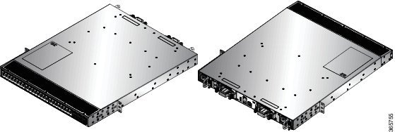
Rack Mount the Chassis
The chassis can be mounted on a 4-post or a 2-post rack based on the type of the chassis and the rack requirement.
-
4-Post Rack-The following sections explain the mounting of the chassis on a 4-post rack:
-
Rack-Mount the Chassis in a 4-Post Rack — Procedure 1- Contains the procedures for mounting the Cisco NCS-55A1-24H, Cisco NCS 5501, Cisco NCS 5501-SE, Cisco NCS-55A1-48Q6H, Cisco NCS-55A1-24Q6H-S, Cisco NCS-55A1-24Q6H-SS, Cisco NCS 55A1-36H-S, Cisco NCS 55A1-36H-SE-S, Cisco NCS 5502, and Cisco NCS 5502-SE chassis.
To mount the Cisco NCS 55A2-MOD-S, Cisco 55A2-MOD-HD-S, Cisco NCS 55A2-MOD-SE-S, Cisco NCS-55A2-MOD-HX-S, and Cisco NC55A2-MOD-SE-H-S chassis on the front post of the 4-post rack, follow the steps in Rack Mount the Chassis in a 2 Post Rack — Procedure 2.
-
Rack Mount the Chassis in a 4-Post Rack — Procedure 2- Contains the procedures for mounting the Cisco NCS-55A2-MOD-HD-S, Cisco NCS-55A2-MOD-HX-S and Cisco NC55A2-MOD-SE-H-S chassis.
-
-
2-Post Rack-The following sections explain the mounting of the chassis on a 2-post rack:
-
Rack-Mount the Chassis in a 2-Post Rack — Procedure 1- Contains procedures for mounting the Cisco NCS-55A1-24H, Cisco NCS 5501, Cisco NCS 5501-SE, Cisco NCS-55A1-24Q6H-S, and Cisco NCS-55A1-24Q6H-SS,
-
Rack Mount the Chassis in a 2 Post Rack — Procedure 2- Contains procedures for mounting the Cisco NCS-55A2-MOD-S, Cisco NCS-55A2-MOD-HD-S, Cisco NCS-55A2-MOD-SE-S, Cisco NCS-55A2-MOD-HX-S, and Cisco NC55A2-MOD-SE-H-S
-
Rack-Mount the Chassis in a 4-Post Rack — Procedure 1
This section describes how to use the rack-mount kit that is provided with the router to install the router in a 4-post rack.
 Caution |
If the rack is on wheels, ensure that the brakes are engaged or that the rack is otherwise stabilized. |
 Note |
To mount the Cisco NCS 55A2-MOD-S, Cisco 55A2-MOD-HD-S, Cisco NCS 55A2-MOD-SE-S, Cisco NCS-55A2-MOD-HX-S, and Cisco NC55A2-MOD-SE-H-S chassis on the front post of the 4-post rack, follow the steps in Rack Mount the Chassis in a 2 Post Rack — Procedure 2. |
The following table lists the items that are contained in the rack-mount kit.
|
Quantity |
Part Description |
|---|---|
|
2 |
Rack-mount brackets |
|
12 |
M4 x 6-mm Phillips flat-head screws |
|
2 |
M5 x 12mm Phillips pan-head screws |
|
2 |
Rack-mount guides |
|
2 |
Rack-mount slider rails |
|
1 |
Grounding lug |
|
Quantity |
Part Description |
|---|---|
|
2 |
Rack-mount brackets |
|
14 |
M4 x 6-mm Phillips flat-head screws |
|
2 |
M4 x 6-mm Phillips pan-head screws |
|
2 |
Rack-mount guides |
|
2 |
Rack-mount slider rails |
|
1 |
Grounding cover plate |
|
1 |
Grounding lug |
|
Quantity |
Part Description |
|---|---|
|
2 |
Rack-mount brackets |
|
18 |
M4 x 8-mm Phillips flat-head screws |
|
2 |
M4 x 8mm Phillips pan-head screws |
|
2 |
Rack-mount guides |
|
2 |
Rack-mount slider rails |
|
1 |
Grounding cover plate |
|
1 |
Grounding lug |
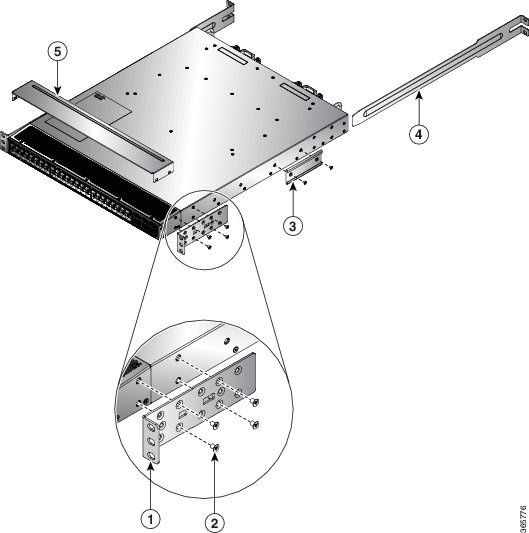
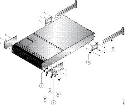
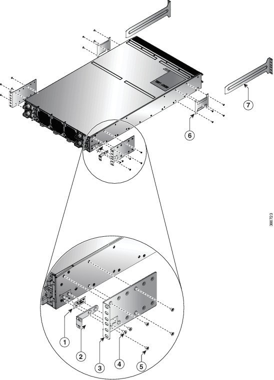
Procedure
|
Step 1 |
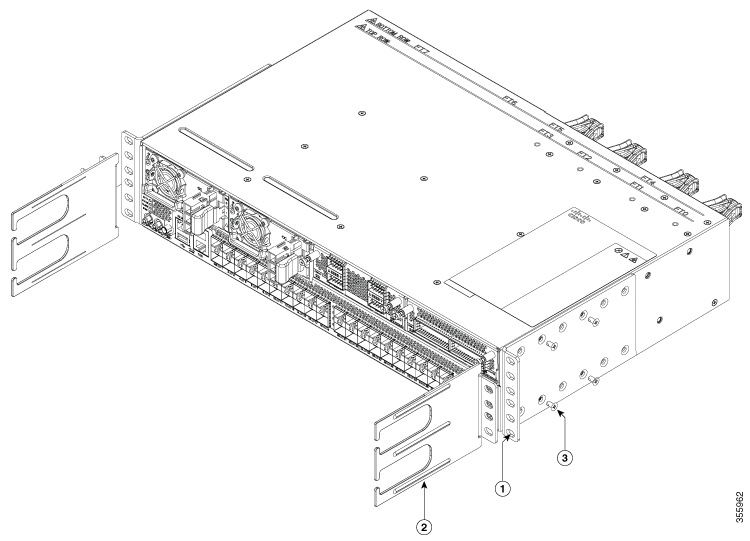
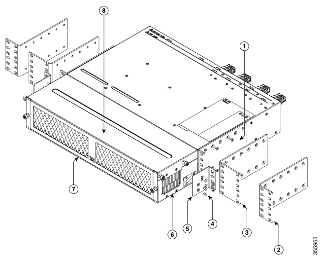
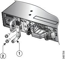
Install the rack-mount brackets to the router as follows:
|
||||||||||||||||||||||||||||||||||||||||||||||||||
|
Step 2 |
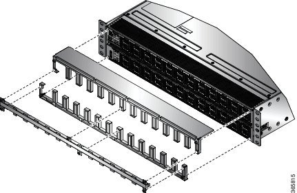
Cisco NCS-55A1-24H, Cisco NCS 55A1-36H-S, Cisco NCS 55A1-36H-SE-S, NCS 5501, and NCS 5501-SE: The top plate is required for NEBS compliance when the router is installed with the ports in the cold aisle (port-side air intake). Install the top plate by pressing the ends of the plate on to the rack-mount brackets.
|
||||||||||||||||||||||||||||||||||||||||||||||||||
|
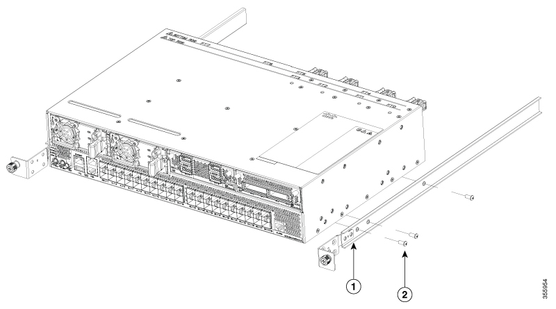
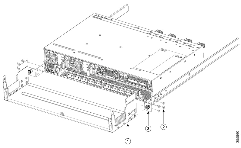
Step 3 |
Install the two rack-mount guides on the chassis as follows:
|
||||||||||||||||||||||||||||||||||||||||||||||||||
|
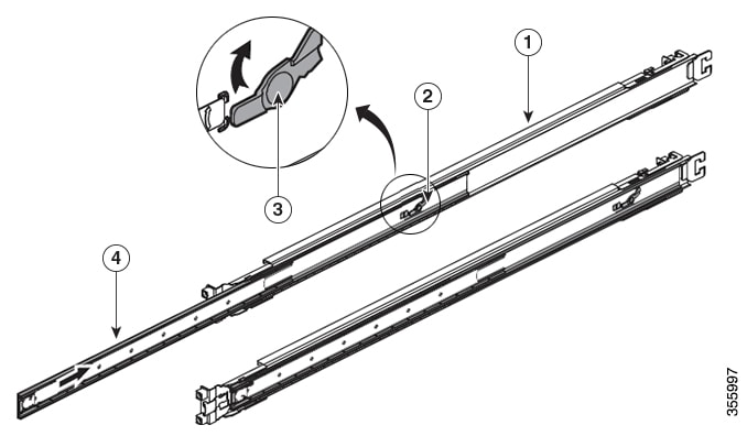
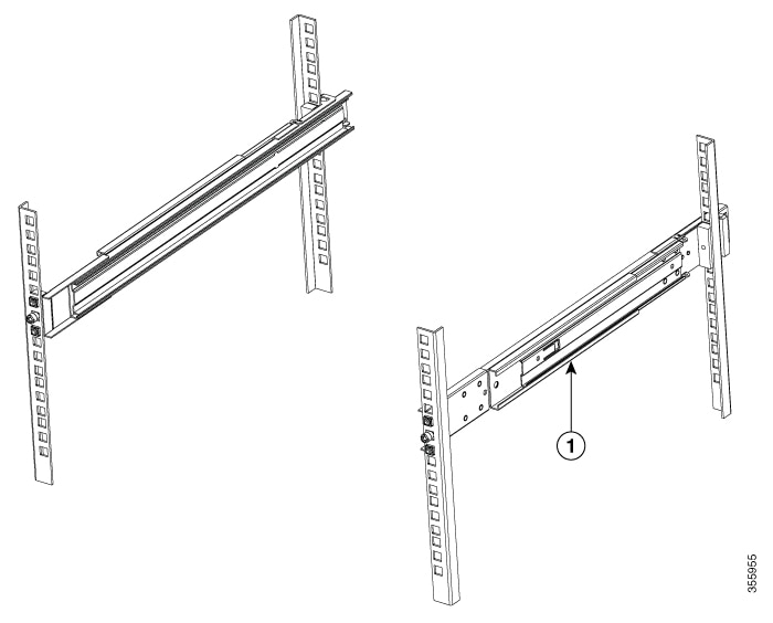
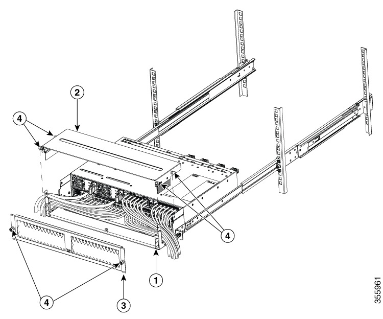
Step 4 |
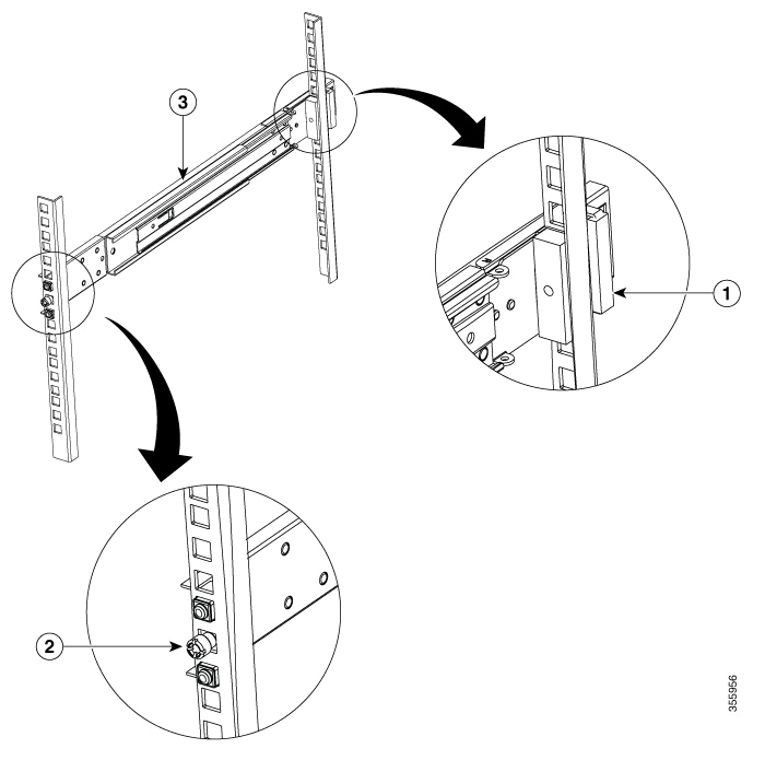
Install the slider rails to the rack as follows: |
||||||||||||||||||||||||||||||||||||||||||||||||||
|
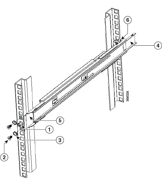
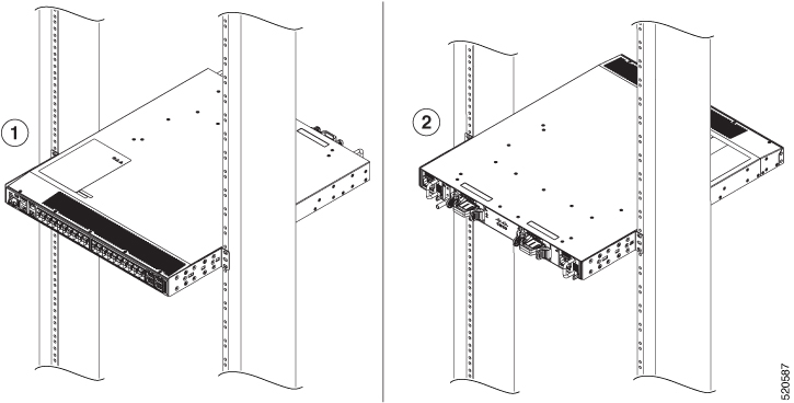
Step 5 |
Insert the router into the rack and attach it as follows: |
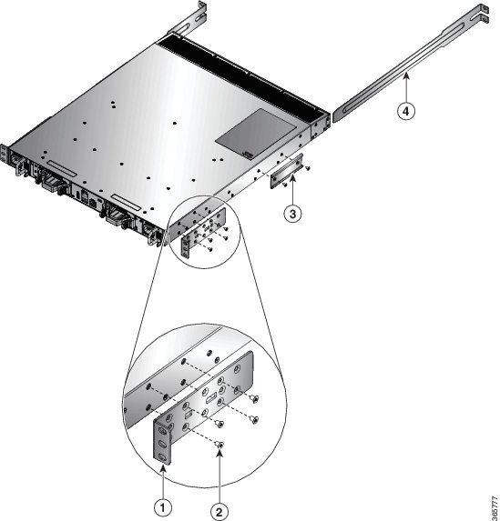
Rack Mount the Chassis in a 4-Post Rack — Procedure 2
This section describes how to install the Cisco NCS-55A2-MOD-HD-S, Cisco NCS-55A2-MOD-HX-S and Cisco NC55A2-MOD-SE-H-S chassis on the 4-post rack, using sliders.
Sliders
The sliders are used to install the Cisco NCS-55A2-MOD-HX-S and Cisco NC55A2-MOD-SE-H-S chassis on a 4-post outdoor rack. Sliders are used to access the fan trays in the chassis easily during maintenance.
The sliders are designed such that the air filters (NCS-55A2-FLTR-FW) can also be accomodated in the chassis installation. There are two types of sliders:
-
NC55-2RU-ACC-SL1: Designed for custom made cabinets that are 476 mm wide (min. 650 x650 mm), or for cabinets with equivalent specifications.
Rack Requirements to Install NC55-2RU-ACC-SL1:
-
4-post rack
-
476 cm wide center to center rail mounting.
-
The width between the front rack-mounting rails must be at least 17.75 inches (45.0 cm)
-
The minimum spacing for the bend radius for fiber-optic cables should have the front-mounting rails of the cabinet offset from the front door by a minimum of 4.7 inches (12.0 cm).
-
The minimum spacing between the front-mounting rails of the cabinet to the inner surface of the front door shall be min. 5.8 inches (14.7 cm). Depend on cabinet ambient thermal set-point this distance can change.
-
The distance between the outside face of the front mounting rail and the outside face of the back-mounting rail should be 16.0 to 19.9 inches (40.7to 50.5 cm) to allow for rear-bracket installation.
-
-
NC55-2RU-ACC-SL2: Designed for 19-inch (min. 650 x650 mm) EIA cabinet standard 4-post rack.
Rack Requirements to Install NC55-2RU-ACC-SL2:
-
Standard 19-inch (48.3 cm) (four-post EIA cabinet, with mounting rails that conform to English universal hole spacing per section 1 of ANSI/EIA-310-D-1992.)
-
The width between the front rack-mounting rails must be at least 17.75 inches (45.0 cm.)
-
The minimum spacing between the front-mounting rails of the cabinet to the inner surface of the front door shall be min. 5.8 inches (14.7 cm). Depending on the cabinet ambient thermal set-point this minimum distance can change.
-
The minimum spacing for the bend radius for fiber-optic cables should have the front-mounting rails of the cabinet offset from the front door by a minimum of 4.7 inches (12.0 cm).
-
The distance between the outside face of the front mounting rail and the outside face of the back-mounting rail should be 16.5 to 19 inches (41.9 to 48.26 cm) to allow for rear-bracket installation.
-
The slider assembly consists of three parts:
-
Inner Slider Member
-
Middle Slider Member
-
Outer Slider Member
Note |
The front end of the outer slider member may vary between NC55-2RU-ACC-SL1 and NC55-2RU-ACC-SL2. The outer slider member of NC55-2RU-ACC-SL2 is mounted to the front post with 2 screws, whereas, the outer slider member of NC55-2RU-ACC-SL1 is passed through the rack holes of the front post and latched to the rack. |
|
1 |
Outer Slider Member |
2 |
Middle Slider Member |
|
3 |
Unlock Feature on the Middle Slider Member |
4 |
Inner Slider Member |
|
Quantity |
Part Description |
|---|---|
|
2 |
Rack-mount brackets |
|
2 |
Rack-mount slider rails |
|
8 |
M4 x 8-mm Phillips counter sink screws |
|
2 |
M4 x 8-mm Phillips pan-head screws |
|
1 |
Grounding lug |
|
6 |
(Only NC55-2RU-ACC-SL1) M4 x 10-mm Phillips pan-head screws |
|
6 |
(Only NC55-2RU-ACC-SL2) M4 x 8-mm Phillips flat-head screws |
|
4 |
(Only NC55-2RU-ACC-SL2) washers |
|
4 |
(Only NC55-2RU-ACC-SL2) 10-32 counter sink screws |
|
4 |
(Only NC55-2RU-ACC-SL2) 9.1 mm rack mount pins |
|
4 |
(Only NC55-2RU-ACC-SL2) 8.8 mm rack mount pins |
Procedure
|
Step 1 |
Remove the inner slider member from the slider assembly, by depressing the white tab present at the front of the slider assembly (on the outer slider member). 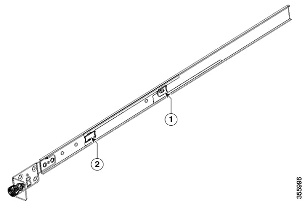
|
||||||||||||||||||||||||||||
|
Step 2 |
Push the unlock feature of the middle slider member and slide the middle slider member back to the slider assembly. |
||||||||||||||||||||||||||||
|
Step 3 |
Attach the inner slider member to the sides of the chassis:
|
||||||||||||||||||||||||||||
|
Step 4 |
Install the outer slider member to the rack:
|
||||||||||||||||||||||||||||
|
Step 5 |
Pull the middle slider member from the slider assembly to an extended position. 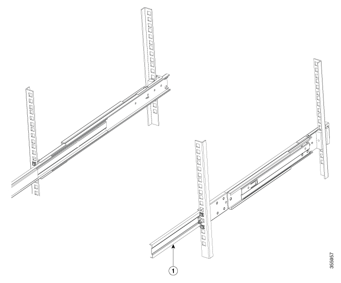
|
||||||||||||||||||||||||||||
|
Step 6 |
Insert the chassis that already has the inner slider members attached, to the middle slider member on the rack. |
||||||||||||||||||||||||||||
|
Step 7 |
Slide the chassis into middle slider member until it cannot be pushed further. 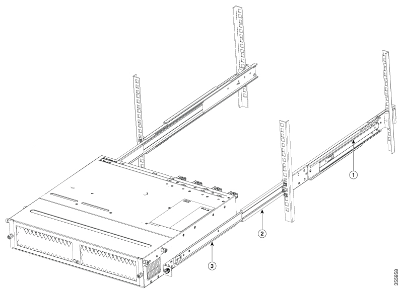
|
||||||||||||||||||||||||||||
|
Step 8 |
Pull the blue release tab on the inner slider member on both sides simultaneously to release the lock position. Continue to push the chassis to the rack. 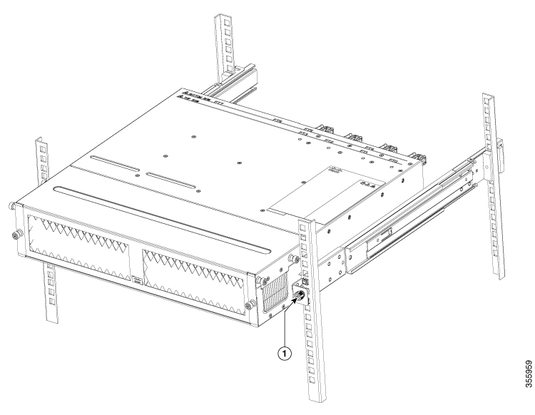 |
||||||||||||||||||||||||||||
|
Step 9 |
Tighten the thumbscrews on either side of the chassis, that is aligned with the screw thread adapter of the outer slider member through the rack holes. |
What to do next
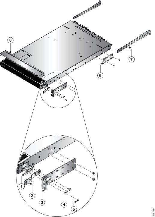
Rack-Mount the Chassis in a 2-Post Rack — Procedure 1
This section describes how to use the rack-mount kit provided with the router to install the following routers into a cabinet or 2-post rack:
-
Cisco NCS-55A1-24H
-
Cisco NCS 5501
-
Cisco NCS 5501-SE
-
Cisco NCS-55A1-24Q6H-S
-
Cisco NCS-55A1-24Q6H-SS
Caution |
If the rack is on wheels, ensure that the brakes are engaged or that the rack is otherwise stabilized. |
The following table lists the items contained in the rack-mount kit provided with the routers.
|
Quantity |
Part Description |
|---|---|
|
2 |
Rack-mount brackets |
|
8 |
M4 x 0.7 x 6-mm Phillips flat-head screws |
Procedure
|
Step 1 |
Install two rack-mount brackets to the router as follows:
|
||||
|
Step 2 |
Install the router onto the 2-post rack as follows:
|
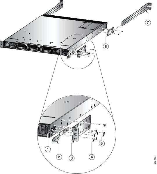
Rack Mount the Chassis in a 2 Post Rack — Procedure 2
This section describes how to use the rack-mount kit provided with the chassis, to install the following chassis into a cabinet or a 2-post rack:
-
Cisco NCS-55A2-MOD-S
-
Cisco NCS-55A2-MOD-HD-S
-
Cisco NCS-55A2-MOD-SE-S
-
Cisco NCS-55A2-MOD-HX-S
-
Cisco NC55A2-MOD-SE-H-S
Caution |
If the rack is on wheels, ensure that the brakes are engaged or that the rack is otherwise stabilized. |
The following table lists the items contained in the rack-mount kit provided with the routers.
|
Quantity |
Part Description |
|---|---|
|
2 |
Rack-mount brackets |
|
8 |
M4 x 8-mm Phillips counter sink screws |
Depending on the type of the rack, the following rack mount brackets can be used:
-
19-inch Rack: NC55A2-RCKMNT-19 brackets
-
23-inch Rack: NC55A2-RCKMNT-23 brackets
-
ETSI Rack: N55A2-RCKMNT-ETSI brackets
Note |
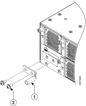
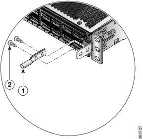
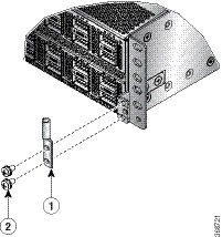
In addition, use the cable guide bracket (NCS-55A2-CAB-MGMT) for managing the cables in Cisco NCS 55A2-MOD-SE-S, Cisco NCS-55A2-MOD-HX-S and Cisco NC55A2-MOD-SE-H-S. The cable guide bracket is optional and is obtained in the accessory kit (NC55-2RU-ACCX-KIT). |
Procedure
|
Step 1 |
Install two rack-mount brackets to the router as follows:
|
||||||||
|
Step 2 |
Install the router onto the 2-post rack as follows:
|


 Feedback