Hardware Installation Guide for Cisco NCS 5500 Series Fixed-Port Routers
Bias-Free Language
The documentation set for this product strives to use bias-free language. For the purposes of this documentation set, bias-free is defined as language that does not imply discrimination based on age, disability, gender, racial identity, ethnic identity, sexual orientation, socioeconomic status, and intersectionality. Exceptions may be present in the documentation due to language that is hardcoded in the user interfaces of the product software, language used based on RFP documentation, or language that is used by a referenced third-party product. Learn more about how Cisco is using Inclusive Language.
The images in this chapter are only for representation purposes, unless specified otherwise. The chassis' actual appearance
and size may vary.
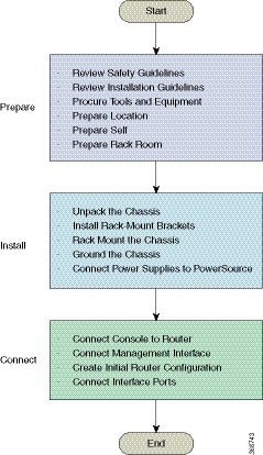
Review Installation Roadmap
The figure, Installation Workflow, lists the steps to install Cisco NCS 5500 Series fixed-port chassis and its components
and prepare the system for operation. Use this workflow as a reference to ensure that all components are properly installed
in the correct order. For information about a step, see the respective section of this installation guide.
Figure 1. Installation Workflow
Review Safety
Guidelines
Before you perform any procedure in this document, review the safety guidelines in this section to avoid injuring yourself
or damaging the equipment. The following guidelines are for your safety and to protect equipment. Because the guidelines do
not include all hazards, be constantly alert.
Keep the work area clear, smoke and dust-free during and after installation. Do not allow dirt or debris to enter into any
laser-based components.
Do not wear loose clothing, jewelry, or other items that could get caught in the router or other associated components.
Cisco equipment operates safely when used in accordance with its specifications and product-usage instructions.
Be sure to power down a fixed configuration PDU or modular configuration power shelf before removing it from the chassis.
If potentially hazardous conditions exist, do not work alone.
Take care when connecting multiple units to the supply circuit so that wiring is not overloaded.
This equipment must be grounded. Never defeat the ground conductor or operate the equipment in the absence of a suitably installed
ground conductor. Contact the appropriate electrical inspection authority or an electrician if you are uncertain about whether
suitable grounding is available.
To prevent personal injury or damage to the chassis, never attempt to lift or tilt the chassis using the handles on modules
(such as power supplies, fans, or cards); these types of handles are not designed to support the weight of the unit.
Hazardous voltage or energy is present on the backplane when the system is operating. Use caution when servicing.
When installing or replacing the unit, the ground connection must always be made first and disconnected last.
The rack stabilizing mechanism must be in place, or the rack must be bolted to the floor before you slide the unit out for
servicing. Failure to stabilize the rack may cause the rack to tip over.
Warning
Statement 1071—Warning Definition
IMPORTANT SAFETY INSTRUCTIONS
Before you work on any equipment, be aware of the hazards involved with electrical circuitry and be familiar with standard
practices for preventing accidents. Read the installation instructions before using, installing, or connecting the system
to the power source. Use the statement number at the beginning of each warning statement to locate its translation in the
translated safety warnings for this device.
SAVE THESE INSTRUCTIONS
Warning
Statement
1051—Laser Radiation
Invisible laser radiation may be emitted from disconnected fibers or connectors. Do
not stare into beams or view directly with optical instruments.
Cautions and Regulatory Compliance Statements for NEBS
The following are NEBS GR-1089-CORE cautions, regulatory compliance statements, and requirements:
The intra-building port(s) of the equipment or subassembly must use shielded intra-building cabling/wiring that is grounded
at both ends.
Caution
The intra-building port(s) of the equipment or subassembly is suitable for connection to intra-building or unexposed wiring
or cabling only. The intra-building port(s) of the equipment or subassembly must not be metallically connected to interfaces
which connect to the OSP or its wiring. These interfaces are designed for use as intra-building interfaces only (Type 2 or
Type 4 ports as described in GR-1089-CORE) and require isolation from the exposed OSP cabling. The addition of primary protectors
is not sufficient protection in order to connect these interfaces metallically to OSP wiring.
Products that have AC power ports that are intended for deployments where an external Surge Protective Device (SPD) is utilized
at the AC power service equipment (see definition in National Electric Code).
This product is designed for a Common Bonding Network (CBN) installation.
This product can be installed in network telecommunication facilities or locations where the National Electric Code applies.
An electrical conducting path shall exist between the product chassis and the metal surface of the enclosure or rack in which
it is mounted or to a grounding conductor. Electrical continuity shall be provided by using thread-forming type mounting screws
that remove any paint or nonconductive coatings and establish a metal-to-metal contact. Any paint or other nonconductive coatings
shall be removed on the surfaces between the mounting hardware and the enclosure or rack. The surfaces shall be cleaned and
an antioxidant applied before installation.
The DC return connection to this system should remain isolated from the system frame and chassis (DC-I).
The nominal DC operating voltage -48 VDC.
Review Site Selection Guidelines
This equipment requires specific environmental operating conditions such as temperature, humidity, altitude, and vibration
for better performance and reliability. The following sections provide guidelines for installation of the equipment to ensure
operating conditions are within specified limits mentioned in the Cisco Network Convergence System 5500 Series: 55A2 Chassis Data Sheet. There are two categories of installation sites: Central Office and Outside Plant.
Central Offices (COs) and Similar Facilities
Equipment qualified for GR-63-CORE is intended for installation in Central Offices (COs) and similar facilities.
Temperature and humidity levels of central offices shall be as per GR-63-CORE - Issue 5, Table 4-4 and Figure 4-1. Maximum
allowable temperature and humidity levels must be within the values mentioned in the data sheets. Always maintain absolute
humidity levels less than 0.024 Kg of water vapor/Kg of dry air. We do not recommend installations where condensation may
occur or where equipment is exposed to high humidity for long duration.
Environmental pollutant limits of central offices shall be as per GR-63-CORE Table 2-4.
Outside Plant Installation (OSP)
Equipment qualified for GR-3108-CORE is intended for installation in outside plant applications (OSP).
Temperature and humidity levels of OSP installation sites shall be as per GR-3108-CORE Table 1-1. Maximum allowable inlet
air temperature and humidity levels must be within the values mentioned in the data sheets. Environments with relative humidity
above 85% or where condensation may occur is not acceptable for equipment qualified for GR-3108-CORE Class 1 and 2.
Environmental pollutant limits of OSP sites shall be as per GR-63-CORE Table 2-3.
We recommended that you check the concentration of pollutants periodically at CO and OSP sites. Equipment should be provided
with necessary protection to ensure it is not exposed to high concentration level of pollutants.
Caution
Installation in highly corrosive areas is not recommended. Examples of highly corrosive areas include: near the sea, rivers,
and large bodies of water where high humidity persist for long peroids of time; highly polluted areas such as sites less than
10 meters from high traffic roadways; areas with high industrial pollutants.
Caution
Equipment should be provided with necessary protection against insects, pests, etc.
Review Outside Plant (OSP) Guidelines
The following sections provide guidelines for the NCS 55A2 temperature-hardened, conformal coated chassis (NCS-55A2-MOD-HX-S,
NC55A2-MOD-SE-H-S) for outside plant installation (OSP).
Cabinet Selection Guidelines
For an outside plant installation, it is required that the equipment be protected against airborne contaminants, dust, moisture,
insects, pests, corrosive gases, polluted air, or other reactive elements present in the outside air. The table below provides
guidelines for cabinet selection.
Central Office (CO)
Outside Plant (OSP)
Open rack with no front and rear doors
Yes
No
Ventilated cabinets with normal air filter at intake and fans
Yes
No
Sealed cabinets with heat exchanger, meeting NEMA-4/IP66 or IP65 protection
Yes
Yes
Sealed cabinets with air-conditioners, meeting NEMA-4/IP66 or IP65 protection
Yes
Yes
Equipment (PID) Selection Guidelines
Data sheet provides details of PID, respective maximum operating conditions and standards that equipment comply with. This
section provides guidelines of selection of PID based on environmental conditions. Below table shows PIDs and environmental
conditions in which it can be installed.
PID
Central Office (CO)
Outside Plant (OSP)
NCS-55A2-MOD-S
Yes
No
NCS-55A2-MOD-SE-S
Yes
No
NCS-55A2-MOD-HD-S
Yes
No
NCS-55A2-MOD-HX-S
Yes
Yes
NC55A2-MOD-SE-H-S
Yes
Yes
Selection of Air Filter Box
Some sites may have high suspended dust concentration. Suspended dust flows into the air breathing equipment along with cooling
and caus earlier failures. Air filters can be considered to minimize the course particles intrusion into the equipment and
mitigate early failures. Table below show guidelines for selection of air filters.
Central Office (CO)
Outside Plant (OSP)
Dust concentration levels
< 20µg/m3
>/= 20µg/m3
< 90µg/m3
NCS-55A2-FLTR-FW
Optional
Recommended
Recommended
Note
µg/m3: Micrograms per cubic meter
Air Filter Maintenance
A periodic health check of the filter, every three months based on the level of dust in the environment, helps in avoiding
over clogging of the filters and provide a better life. This product's filter is used as a single-use component. If the product
is installed in a controlled environment, check and replace the filter every three months, otherwise replace the filter every
month with PID (NCS-55A2-FLTR-FW=).
Review Installation
Guidelines
Before installing the
chassis, verify that these guidelines are met:
Site is properly prepared so that there is sufficient room for installation and maintenance. For specifications on the clearances
required for chassis installation, see Clearance Requirements in a Solid Door Cabinet.
Chassis is mounted
at the bottom of the rack if it is the only unit in the rack.
When mounting the
chassis in a partially filled rack, load the rack from the bottom to the top
with the heaviest component at the bottom of the rack.
If the rack is
provided with stabilizing devices, install the stabilizers before mounting or
servicing the chassis in the rack.
Airflow around the
chassis and through the vents is unrestricted.
Cabling is away
from sources of electrical noise, such as radios, power lines, and fluorescent
lighting fixtures. Make sure that the cabling is safely away from other devices
that might damage the cables.
For cable requirements for optical module connections, see the Transceivers, Connectors, and Cables section. Each port must match the wave-length specifications on the other end of the cable, and the cable must not exceed
the maximum cable length.
Clearance Requirements in a Solid Door Cabinet
The fixed-port chassis requires front-to-back airflow. Leave at least 6.0 in. (15.24 cm) front and rear clearance for air
intake/exhaust at room temperature up to 55C, and leave at least 4.0 in. (10.16 cm) front and rear clearance for air intake/exhaust
at room temperature up to 40C. Leave an additional 6.0 in. (15.24 cm)/4.0 in. (10.16 cm) rear clearance for removal and installation
of power supplies and fan modules.
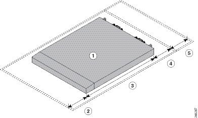
Figure 2. Clearances Required Around the Chassis
1
Chassis
4
6.0 in. (15.24 cm) front clearance for air intake/exhaust at room temperature up to 55C
4.0 in. (10.16 cm) front clearance for air intake/exhaust at room temperature up to 40C
2
6.0 in. (15.24 cm) front clearance for air intake/exhaust at room temperature up to 55C
4.0 in. (10.16 cm) front clearance for air intake/exhaust at room temperature up to 40C
5
Additional 6.0 in. (15.24 cm)/4.0 in. (10.16 cm) rear clearance for removal and installation of power supplies and fan modules.
3
Chassis depth
Note
Clearance for air intake and exhaust is not required if the fixed-port chassis is placed inside perforated door cabinet or
an open cabinet.
Clearance Requirements for Outside Plant Enclosure (OSP)
NCS-55A2-MOD-HX-S and NC55A2-MOD-SE-H-S are temperature-hardened, conformal coated chassis that can be installed in OPT enclosures.
Observe the following clearance requirements when installing these chassis in OSP enclosures:
Installation and Options
Front Clearance
Rear Clearance
Chassis with slider and air filter box, with 1RU space between chassis
6 in. (152.4 mm) @ 158°F (70°C)
2 in. (50.8 mm) @ 158°F (70°C)
Chassis with bracket and air filter box, with 1RU space between chassis
Chassis with bracket, with 1RU space between chassis
Chassis with slider and air filter box, with no space between chassis
6 in. (152.4 mm) @ 158°F (70°C)
2 in. (50.8 mm) @ all temperatures
Chassis with bracket and air filter box, with no space between chassis
Chassis with bracket, with no space between chassis
Note
The temperatures are measured at the air inlet to the equipment.
The temperatures are valid at sea level. The maximum allowable temperatures are reduced at higher altitudes. Altitude derating
1°C for every 300m.
The above mentioned maximum allowable temperatures assume that all optics are I-Temp (industrial grade) optics with allowable
optics case temperature up to 85°C.
In case of a single fan failure, the maximum allowable temperature will be less than specified.
In case the air filter is clogged, the temperature alarm may be raised at temperatures below the listed temperatures.
Airflow
Direction
The airflow through the fan trays and power supplies on the Cisco NCS 5500 series router is either from the port side exhaust or the port side intake, depending on how the modules were ordered. To
ensure proper airflow, you must make sure that when you install the router its air intake is positioned in a cold aisle and
the air exhaust is positioned in a hot aisle.
Procure Tools and
Equipment
Obtain these necessary
tools and equipment for installing the chassis:
Number 1 and number 2 Phillips screwdrivers with torque capability to rack-mount the chassis
3/16-inch flat-blade screwdriver
Tape measure and level
ESD wrist strap or other grounding device
Antistatic mat or antistatic foam
A Torx T15 screwdriver, or the Torx T15 key to install adapters
Grounding cable (6 AWG recommended), sized according to local and
national installation requirements; the required length depends on the
proximity of the switch to proper grounding facilities
Ground lug (1)
Crimping tool large enough to accommodate the girth of the lug
Wire-stripping tool
(ANSI) Pair of 19-inch mounting brackets
M4 screws to fix brackets (16)
M4 screws to fix ground lug (2)
Accessory Kits for Fixed Port Routers
The following table contains the accessory kit PIDs and the items present in the accessory kits of the fixed port routers.
The rack mount kit present in the accessory kit contains the screws and brackets required for installation.
Table 1. Accessory Kits Information
Router
Accessory Kit-1
Items in Accessory Kit -1
Accessory Kit – 2 (NEBS)
Items in Accessory Kit-2
Cisco NCS-55A1-24H
NCS-1RU-ACC-KIT
Rack mount kit and ground lug kit
NC55-24H-NEBS-KIT
Rack mount kit, ground lug kit, and air baffle for NEBS
Cisco NCS 5501
NCS-1RU-ACC-KIT
Rack mount kit and ground lug kit
NCS-1RU-NEBS-KIT
Rack mount kit, ground lug kit, and air baffle for NEBS
Cisco NCS 5501-SE
NCS-1RU-ACC-KIT
Rack mount kit and ground lug kit
NCS-1RU-NEBS-KIT
Rack mount kit, ground lug kit, ground bracket, and air baffle for NEBS
Cisco NCS-55A1-48Q6H
NCS-1RU-ACC-KIT
Rack mount kit and ground lug kit
-
-
Cisco NCS-55A1-24Q6H-S
NCS-1RU-ACC-KIT
Rack mount kit and ground lug kit
-
-
Cisco NCS-55A1-24Q6H-SS
NCS-1RU-ACC-KIT
Rack mount kit and ground lug kit
-
-
Cisco NCS 55A1-36H-S
NC55-A1-ACC-KIT
Rack mount kit and ground lug kit
NC55-A1-NEBS-KIT
Rack mount kit, ground lug kit, ground bracket, and air baffle for NEBS
Cisco NCS 55A1-36H-SE-S
NC55-A1-ACC-KIT
Rack mount kit and ground lug kit
NC55-A1-NEBS-KIT
Rack mount kit, ground lug kit, ground bracket, and air baffle for NEBS
Cisco NCS 5502
NCS-2RU-ACC-KIT
Rack mount kit and ground lug kit
-
-
Cisco NCS 5502-SE
NCS-2RU-ACC-KIT
Rack mount kit and ground lug kit
-
-
Cisco NCS 55A2-MOD-S
NCS-2RU-ACC-KIT
Rack mount kit and ground lug kit
-
-
Cisco 55A2-MOD-HD-S
NCS-2RU-ACC-KIT
Rack mount kit and ground lug kit
-
-
Cisco NCS 55A2-MOD-SE-S
NCS-2RU-ACC-KIT
Rack mount kit and ground lug kit
-
-
Cisco NCS-55A2-MOD-HX-S
NC55-2RU-ACCX-KIT
Conformal Coated Rack mount kit and ground lug kit
-
-
Cisco NC55A2-MOD-SE-H-S
NC55-2RU-ACCX-KIT
Conformal Coated Rack mount kit and ground lug kit
-
-
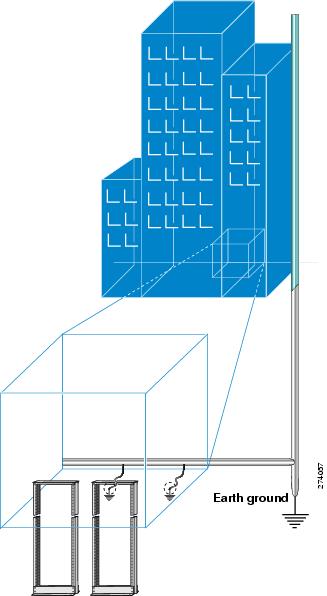
Prepare Your
Location
This section illustrates how the building that houses the chassis must be properly grounded to the earth ground.
Figure 3. Building with Rack Room Connected to Earth Ground
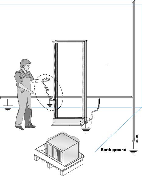
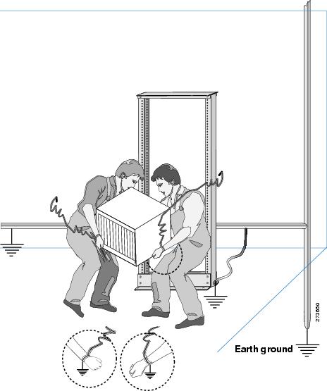
Prepare Yourself
This section
illustrates how to prepare yourself before removing the chassis from the sealed
antistatic bag. The figures show how to cuff the ESD strap around the wrist and
the ground cord that connects the cuff to the ground. ESD wrist straps are the
primary means of controlling static charge on personnel.
Figure 4. Wearing the ESD
Strap
Figure 5. Handling the
Chassis
Prepare Rack for
Chassis Installation
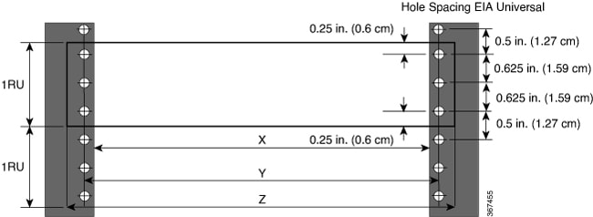
Install the NCS 5500 Series chassis into a standard 19-inch, four-post Electronic Industries Alliance (EIA) cabinet or rack
with mounting rails that conform to English universal hole spacing per section 1 of the ANSI/EIA-310-D-1992 standard.
The spacing between the posts of the rack must be wide enough to accommodate the width of the chassis.
Figure 6. Rack Specification EIA (19 inches and 23 inches)
Table 2. Rack specification EIA (19 inches and 23 inches)
Post Type
Rack Type
Rack Front Opening (X)
Rack Mounting Hole Center-Center (Y)
Mounting Flange Dimension (Z)
4 Post
19 inches (48.3 centimeters)
450.8mm (17.75”)
465mm (18.312”)
482.6mm (19”)
2 Post
4 Post
23 inches (58.4 centimeters)
552.45mm (21.75”)
566.7mm (22.312”)
584.2mm (23”)
2 Post
Before you move the chassis or mount the chassis into the rack, we recommend that you do the following:
Procedure
Step 1
Place the rack where you plan to install the chassis. Ensure that the rack that the chassis is being installed is grounded
to earth ground as instructed in Prepare Your Location.
Step 2
Secure the rack
to the floor.
To bolt the rack
to the floor, a floor bolt kit (also called an anchor embedment kit) is
required. For information on bolting the rack to the floor, consult a company
that specializes in floor mounting kits (such as Hilti; see Hilti.com for
details). Make sure that floor mounting bolts are accessible, especially if
annual retorquing of bolts is required.


 Feedback