- Preface
- Overview of Chassis Installation Steps
- Cisco CRS Carrier Routing System 8-Slot Line Card Chassis Enhanced Router Overview
- Installing Power Components
- Installing Air Circulation Components
- Installing Exterior Components
- Installing Line Cards, PLIMs, and Associated Components
- Removing Chassis Components
- Technical Specifications
- Product IDs
- Installing Line Cards, PLIMs, and Associated Components
- About Installing and Removing Cards and Associated Components
- Guidelines and Warnings for Card Installation and Removal
- Chassis Slot Numbers
- About Impedance Carriers and Slot Covers
- About Distributed Route Processors and Distributed Route Processor PLIMs
- About Small Form-Factor Pluggable (SFP) Modules
- About Hard Drives and PCMCIA Cards
- About Cable Management Brackets
- Installing or Removing a Slot Cover
- About Installing and Removing Cards and Associated Components
- Installing or Removing an Impedance Carrier
Installing Line
Cards, PLIMs, and Associated Components
Installing Line Cards, PLIMs, and Associated Components
This chapter provides instructions on how to install the Cisco CRS 8-Slot Line Card Chassis Enhanced router modular services cards (MSCs), physical layer interface modules (PLIMs), and any associated components. This chapter presents the following topics:
- About Installing and Removing Cards and Associated Components
- Installing or Removing a Slot Cover
- Installing or Removing an Impedance Carrier
- Installing an RP, PRP, or DRP Card
- Installing a Switch Fabric Card
- Installing an MSC, FP, or LSP
- Installing a Physical Layer Interface Module
- Installing a PCMCIA Card
- Installing a Small Form-Factor Pluggable (SFP) Module
- Installing the Front Cable Management Bracket
- Installing the Rear Cable Management Bracket
About Installing and Removing Cards and Associated Components
This section contains some general information about installing and removing cards, PLIMs, and associated components.
- Guidelines and Warnings for Card Installation and Removal
- Chassis Slot Numbers
- About Impedance Carriers and Slot Covers
- About Distributed Route Processors and Distributed Route Processor PLIMs
- About Small Form-Factor Pluggable (SFP) Modules
- About Hard Drives and PCMCIA Cards
- About Cable Management Brackets
Guidelines and Warnings for Card Installation and Removal
This section contains the guidelines for card installation and removal.
 Caution | Removing more than one card at a time can misalign the chassis and may damage the card or chassis when reinserting the cards. Remove and reinsert only one card at a time. |
Online (in-service) insertion and removal (OIR) is supported, enabling you to remove and install cards while the router is operating. OIR is seamless to users on the network, maintains all routing information, and ensures session preservation. Notifying the software or resetting the power is not required. However, you have the option of using the shutdown command before removing a card.
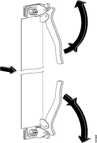
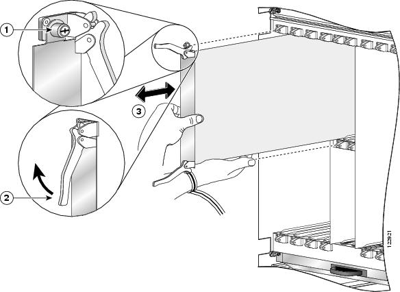
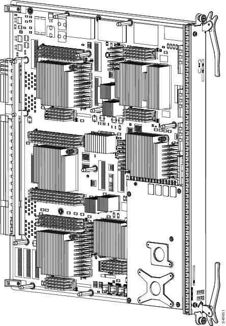
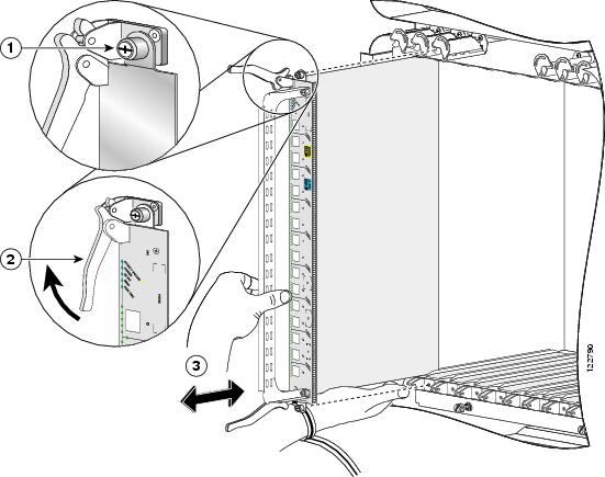
The different cards and PLIMs in the line card chassis are all attached to the chassis itself using a pair of ejector levers and captive screws. The two ejector levers release the card or PLIM from its midplane connector. The exact location of the ejector levers and captive screws varies slightly from card to card, but are in general in the same location: on the upper and bottom of the faceplate of the card. .

|
1 |
Captive screw |
2 |
Ejector lever |
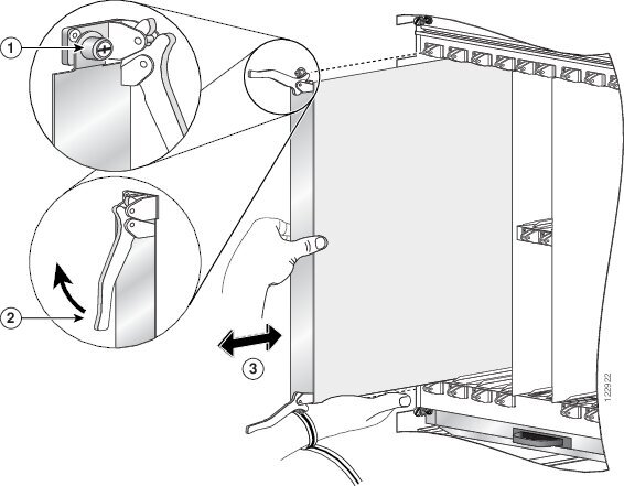
The following figure shows how to operate the ejector levers. Be sure to operate both levers simultaneously.
When shipped, every slot in the chassis contains either an impedance carrier, or is covered by a slot cover (see About Impedance Carriers and Slot Covers).
 Note | While it is not critical for you to install the cards in a certain order, following the card installation recommendations in this chapter will make your installation process easier. |
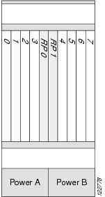
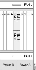
Chassis Slot Numbers
Figure 1 and Figure 2 show the slot numbers for the Cisco CRS 8-Slot Line Card Chassis Enhanced router.
Recommended Order of Card Installation
Card should be installed in a particular order. We recommend the following order when removing the impedance carriers and installing the cards in the chassis (see #con_1361279/fig_1342885 and #con_1361279/fig_1342892):
- Install the RP cards first one card at a time, the left one (slot RP0) before the right one (slot RP1). Tighten the screws only after fully inserting both RP cards.
Note | It is important to engage and partially tighten all screws first, before fully tightening them with a screwdriver. This action helps ensure that all parts are aligned properly in the chassis. |
We recommend that you install fabric cards from left to right, starting from top to bottom, in this order:
-
- Slot SM0
- Slot SM1
- Slot SM2
- Slot SM3
- For the line cards and PLIMs, you must remove one impedance carrier, install a functional board, and tighten the screw; then repeat the process until all cards and PLIMs have been installed.
Cautions and Recommendations
Caution | When you remove a card, always use the ejector levers to ensure that the connector pins disconnect from the midplane in the sequence expected by the router. |
Caution | The router may indicate a hardware failure if you do not follow proper procedures. Remove or install only one card at a time. Allow at least 15 seconds for the router to complete the preceding tasks before removing or installing another card. |
Do not operate the Cisco CRS 8-Slot Line Card Chassis Enhanced router with any slots completely empty; doing so could lead to an airflow bypass condition that diverts airflow from slots containing heat-generating electronics, possibly causing thermal alarms to occur at lower-than-expected ambient temperatures.
To avoid airflow bypass, all slots should be filled with their appropriate cards or impedance carriers. If you have to replace a card, we recommend leaving the card in place in the chassis until you are ready to install the new one.
 Tip | To lessen the possibility of damaging the connectors on the chassis midplane, you should visually inspect the connector pins on the cards before you insert them into the chassis. |
About Impedance Carriers and Slot Covers
When shipped, all slots in the chassis either contain impedance carriers or are covered by slot covers to help maintain chassis stiffness and ensure that the chassis is undamaged during shipment. Four different types of impedance carriers and slot covers exist for the four different sizes of slots in the chassis.
For further information on installing and removing the slot covers and impedance carriers, see Installing a Slot Cover, Removing a Slot Cover, Installing an Impedance Carrier, and Removing an Impedance Carrier.
About Distributed Route Processors and Distributed Route Processor PLIMs
The Cisco CRS Carrier Routing System provides distributed route processor (DRP) support through the installation of DRP PLIMs and DRP cards on the Cisco CRS 8-Slot Line Card Chassis Enhanced router (see #con_1293320/fig_1293331 and #con_1293320/fig_1293338). The installation of DRPs provides you with the ability to configure the system for logical router support and additional processor power for multichassis systems.
For DRP support, you must install both the DRP PLIM in a PLIM slot on the front (PLIM) side of the chassis and a DRP card in the corresponding slot on the rear (MSC) side of the chassis. The DRP PLIM and DRP cards are installed in the same manner as regular PLIMs and MSCs. See Installing a Physical Layer Interface Module or Installing an MSC, FP, or LSP for further information.
DRPs contain two CPU complexes, independent of each other, each with its own hard drive. In addition, the DRP provides you with two PCMCIA card slots, similar to the RP. For further information, see About Hard Drives and PCMCIA Cards. For installation or removal information, see Installing a Physical Layer Interface Module.
About Small Form-Factor Pluggable (SFP) Modules
The SFP module for the line card chassis uses the bale clasp latch type.
Caution | Protect the SFP modules by inserting clean dust covers into them after the cables are removed from them. Be sure to clean the optic surfaces of the fiber cables before you plug them back into the optical ports of another SFP module. Avoid getting dust and other contaminants into the optical ports of the SFP modules: The optics do not work correctly when obstructed with dust. |
Note | Only the 16-port OC-48c/STM-16c MSC uses SFP modules. |
About Hard Drives and PCMCIA Cards
Optional and replaceable hard drives and PCMCIA cards are available for the DRP cards.
The hard drive is an IDE hard drive used for gathering debugging information, such as core dumps from the DRPs or MSCs. The IDE hard drive is typically powered down and activated only when there is a need to store data. The drive is not vital to a functioning chassis and is optional.
Note | Core dumps are discoverable only through intervention with the chassis system software. |
Physically, the DRP hard drive is a hot-pluggable PC board and sled-mounted drive with a connector interface that gets cleanly seated into a route processor card. In general, removal and replacement of this drive is not required.
The DRP cards provide two PCMCIA flash slots, each card providing up to 1 GB of flash storage. One of the PCMCIA flash subsystems is accessible externally, is removable, and allows you to transfer images and configurations by plugging in a PCMCIA flash card. The other subsystem is fixed to the DRP, not removable, and for permanent storage of configurations and images.
About Cable Management Brackets
The Cisco CRS 8-Slot Line Card Chassis Enhanced router includes a cable management system that organizes the interface cables entering and exiting the different cards, keeping them out of the way and free of sharp bends.
Caution | Excessive bending of interface cables can damage the cables. |
The Cisco CRS 8-Slot Line Card Chassis Enhanced router arrives preinstalled with a horizontal cable management bracket on the front of the chassis and an optional horizontal cable management bracket is orderable for the rear of the chassis.
Note | If you have Back-to-Back (B2B) installation of fabric cards, it is essential that you use the rear cable management brackets for ideal cable management. |
The following figure shows the front cable management bracket.
The following figure shows the rear cable management bracket.
Installing or Removing a Slot Cover
This section contains the following procedures:
Installing a Slot Cover
This section describes how to install a slot cover in the Cisco CRS 8-Slot Line Card Chassis Enhanced router. The chassis is shipped with slot covers over the switch fabric card and RP card slots; we advise installing slot covers over any empty slots in the chassis. Both slot cover types are installed in the same manner. For more detailed information on the slot covers, see About Impedance Carriers and Slot Covers.
Prerequisites
Before performing this task, remove the front cover, if installed, and ensure that the slot over which you are about to install the cover is empty. See Removing an RP, PRP, or DRP Card, page 7-8 and Removing a Switch Fabric Card, page 7-4 .
Required Tools and Equipment
You need the following tools and part to perform this task:
- ESD-preventive wrist strap
- Number 2 Phillips or number 2 common (flat-head) screwdriver
- Slot cover
Steps
To install a slot cover, follow these steps:
| Step 1 | Attach the ESD-preventive wrist strap to your wrist and connect its leash to an ESD connection socket on the rear (MSC) side or a bare metal surface on the chassis. |
| Step 2 | Using the handle, hold the slot cover in place over the slot. |
| Step 3 | Partially tighten the four captive screws on the front panel of the slot cover (either by hand or with the screwdriver) to make sure that they are both engaged. |
| Step 4 | To seat the slot cover firmly in place, fully tighten the captive screws. |
What to Do Next
After performing this task, reinstall the front cover, if applicable.
Removing a Slot Cover
This section describes how to remove a slot cover from the Cisco CRS 8-Slot Line Card Chassis Enhanced router. The chassis is shipped with slot covers over the switch fabric card and RP card slots. Both slot cover types are removed in the same manner. For more detailed information on the slot covers, see About Impedance Carriers and Slot Covers.
Prerequisites
Before performing this task, remove the front cover, if installed.
Required Tools and Equipment
You need the following tools to perform this task:
- ESD-preventive wrist strap
- Number 2 Phillips or number 2 common (flat-head) screwdriver
Steps
To remove a slot cover, follow these steps:
| Step 1 | Attach the ESD-preventive wrist strap to your wrist and connect its leash to an ESD connection socket on the rear (MSC) side or a bare metal surface on the chassis. |
| Step 2 | Grasp the slot cover with one hand. |
| Step 3 | Loosen the captive screws that attach the slot cover to the chassis. |
| Step 4 | Holding the slot cover by the handle, remove it and set it carefully aside. |
What to Do Next
After performing this task, store the slot cover for later reuse. You may now install a card in the uncovered slot. See Installing a Switch Fabric Card and Installing an RP, PRP, or DRP Card for further details.
Installing or Removing an Impedance Carrier
This section contains the following procedures:
Installing an Impedance Carrier
This section describes how to install an impedance carrier into the Cisco CRS 8-Slot Line Card Chassis Enhanced router. The chassis is shipped with impedance carriers installed in the MSC and PLIM slots. Both impedance carrier types are installed in the same manner. For more detailed information on impedance carriers, see About Impedance Carriers and Slot Covers.
Prerequisites
Before performing this task, remove the front cover, if installed, and ensure that the slot in which you are about to install the impedance carrier is empty. Depending on the slot in which you are installing an impedance carrier, see About Impedance Carriers and Slot Covers, Removing an MSC, FP, or LSP, page 7-6 or Removing a PLIM, page 7-9 .
Required Tools and Equipment
You need the following tools and part to perform this task:
- ESD-preventive wrist strap
- Number 2 Phillips or number 2 common (flat-head) screwdriver
- Impedance carrier (MSC impedance carrier Cisco Product number CRS-MSC-IMPEDANCE=; PLIM impedance carrier Cisco Product number CRS-INT-IMPEDANCE=)
Steps
To install an impedance carrier, follow these steps:
| Step 1 | Attach the ESD-preventive wrist strap to your wrist and connect its leash to an ESD connection socket on the rear (MSC) side or a bare metal surface on the chassis. |
| Step 2 | Use both hands while inserting an impedance carrier. Use one hand on the faceplate and the other hand along the base of the impedance carrier to guide it into a slot. |
| Step 3 | Slide the impedance carrier into the chassis until the captive screw plates are flush with the chassis. |
| Step 4 | Partially tighten the two captive screws on the front panel of the impedance carrier (either by hand or with the screwdriver) to make sure that they are both engaged. |
| Step 5 | To seat the impedance carrier firmly in the slot, fully tighten the captive screws. |
What to Do Next
After performing this task, reinstall the front cover, if applicable.
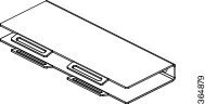
Removing an Impedance Carrier
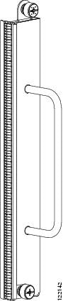
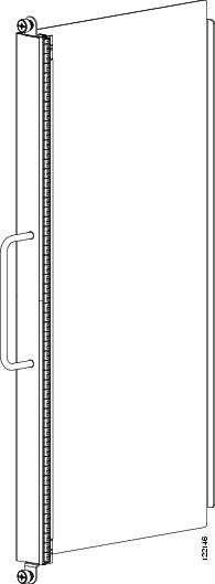
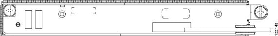
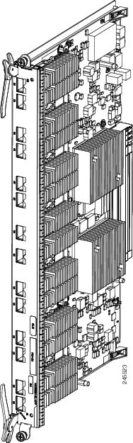
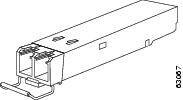
This section describes how to remove an impedance carrier from the Cisco CRS 8-Slot Line Card Chassis Enhanced router. Both impedance carrier types are removed in the same manner. (For reference, #con_1283445/fig_1284640 shows an MSC impedance carrier.) For more detailed information on impedance carriers, see About Impedance Carriers and Slot Covers.
Prerequisites
Before performing this task, remove the front cover, if installed.
Required Tools and Equipment
You need the following tools to perform this task:
- ESD-preventive wrist strap
- Number 2 Phillips or number 2 common (flat-head) screwdriver
Steps
To remove an impedance carrier, follow these steps:
| Step 1 | Attach the ESD-preventive wrist strap to your wrist and connect its leash to an ESD connection socket on the rear (MSC) side or a bare metal surface on the chassis. |
| Step 2 | Identify the impedance carrier to be removed from the card cage. |
| Step 3 | To loosen the impedance carrier from the slot, turn the two captive screws on the front panel of the card counterclockwise. |
| Step 4 | Grasp the impedance carrier handle with one hand and gently pull it halfway from the slot. |
| Step 5 | Place one hand under the impedance carrier to guide it. |
| Step 6 | Holding the impedance carrier underneath and by the handle, pull it from the slot and set it carefully aside. |
What to Do Next
After performing this task, store the impedance carrier for future use. You may now install a card in the uncovered slot. See the Installing an MSC, FP, or LSP and Installing a PLIM for further details.
Installing an RP, PRP, or DRP Card
This section contains the following procedures:
Installing an RP, PRP, or DRP Card
This section describes how to install a route processor (RP), performance route processor (PRP), or distributed route processor (DRP) card in the chassis.
Every Cisco CRS 8-Slot Line Card Chassis Enhanced router contains two RP cards in dedicated slots on the front (PLIM) side of the chassis.
Note | A chassis may not be populated with a mix of RP and PRP cards. Both route processor cards should be of the same type (RP or PRP). If you are using Cisco CRS-X, you must use only PRP cards. |
Note | For enhanced immunity to external electromagnetic disturbance levels of 10V per meter and 10 V RMS, you must use a shielded Ethernet (CAT5 or better STP) cable on the Management Ethernet connection of the RP card (CRS-8-RP). The use of a shielded Ethernet cable on the Management Ethernet connection of the PRP card (CRS-8-PRP-6G or CRS-8-PRP-12G) is optional. The grounded end of the shielded Ethernet cable should be at the RP (or PRP) end. |
Caution | Be careful while handing the PRP line cards to avoid pressing the memory module latches on the daughter board and accidently disengaging the memory modules. For the location of these latches, see the following figure. |
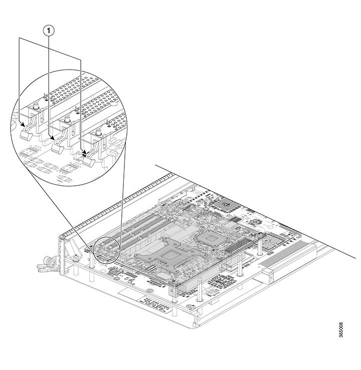
|
1 |
Memory Module Latches |
Prerequisites
Because chassis operation may be impacted by the installation of a route processor card, perform these tasks only if one of the following conditions exists:
- When you are certain that the second RP in the chassis is operational and, if not already the active RP, ready to assume control (this happens automatically)
- When the chassis is undergoing scheduled maintenance
- When the Cisco CRS 8-slot line card chassis is powered down
Failure to follow these guidelines can result in interruptions in data communications and network connectivity.
Before performing this task, remove the front cover, if installed.
Required Tools and Equipment
You need the following tools and part to perform this task:
- ESD-preventive wrist strap
- Number 2 Phillips or number 2 common (flat-head) screwdriver
-
RP, PRP, or DRP card:
- RP card—Cisco product number: CRS-8-RP=
- PRP card—Cisco product number: CRS-8-PRP-6G=
- PRP card—Cisco product number: CRS-8-PRP-12G=
- DRP card—Cisco product number: CRS-DRP-CPU=
Steps
To install an RP or DRP card, follow these steps:
| Step 1 | Attach the ESD-preventive wrist strap to your wrist and connect its leash to an ESD connection socket on the front (PLIM) side or a bare metal surface on the chassis. | ||
| Step 2 | Remove the card from its antistatic packaging. | ||
| Step 3 | Visually inspect the connector pins on the card before you insert it into the chassis. Do not attempt to install a card with bent pins, as this may damage the chassis midplane connectors. | ||
| Step 4 | Identify the card to be replaced in the card cage. Remove any cables connected to the front panel of the card. | ||
| Step 5 | Use the screwdriver to turn the two captive screws on the front panel of the card counterclockwise to loosen the card from the slot. | ||
| Step 6 | Grasp the two card ejector levers and simultaneously pivot both ejector levers 90 degrees away from the front edge of the card carrier to unseat the card from the backplane connector. | ||
| Step 7 | Touching only the metal card carrier, slide the card from the slot and place it directly into an antistatic sack or other ESD-preventive container. If you plan to return the defective card to the factory, repackage it in the shipping container you received with the replacement card. | ||
| Step 8 |
Grasp the card carrier handle with one hand and place your other hand under the carrier to support and guide it into the correct slot. Slide the card halfway into the slot. Avoid touching the card circuitry or any connectors.
| ||
| Step 9 |
Pivot both card ejector levers so that the openings on the card ejector cams at the top and bottom of the card pass over the tabs on each side of the card cage slot.
| ||
| Step 10 |
Continue sliding the card into the card cage slot until the openings on the card ejector cams engage the tabs on each side of the card cage slot.
| ||
| Step 11 | To seat the card in the backplane connector, grasp both card ejector levers and pivot them inward toward the handle in the card carrier until they are flush against the front edge of the card carrier. | ||
| Step 12 | Partially tighten the two captive screws on the front panel of the card (either by hand or with the screwdriver) to make sure that they are both engaged. | ||
| Step 13 | Use the screwdriver to turn the two captive screws on the front panel of the card clockwise to seat the card firmly in the slot. | ||
| Step 14 | Reattach any cables you removed in Step 3. |
What to Do Next
After performing this task, reinstall the front cover, if applicable, and verify that the card has been installed properly (see the Verifying the Installation of an RP, PRP, or DRP Card). If you are performing the initial installation of the system, install the switch fabric cards (see the Installing a Switch Fabric Card).
Verifying the Installation of an RP, PRP, or DRP Card
This section describes how to verify and troubleshoot the installation of a route processor (RP) or distributed route processor (DRP) card in the Cisco CRS 8-Slot Line Card Chassis Enhanced router..
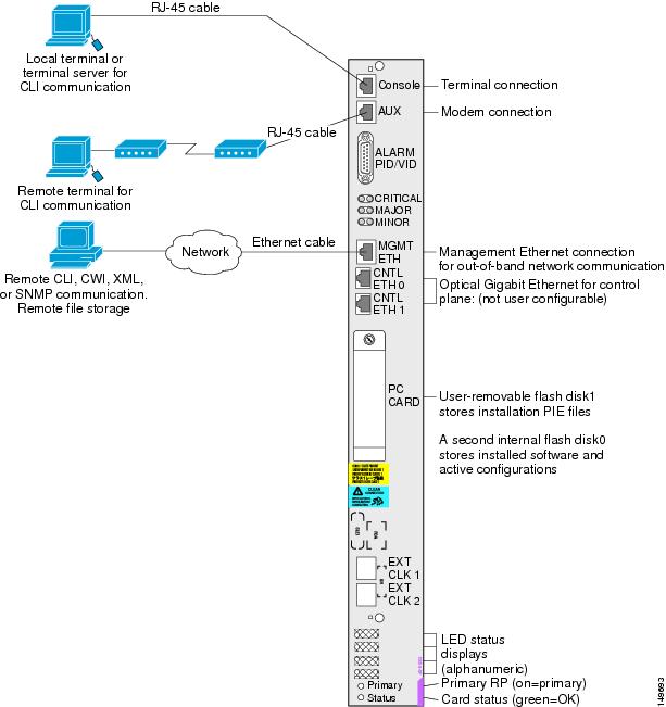
This section describes how to verify that the card has been properly installed. Status indicators on the RP front panel include:
The following figure shows the RP card front panel.
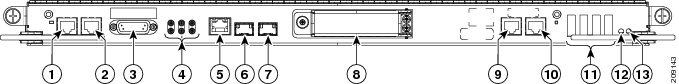
|
1 |
Console port |
6 |
Control Ethernet 0 port |
11 |
Alphanumeric LEDs |
|
2 |
AUX port |
7 |
Control Ethernet 1 port |
12 |
PRIMARY LED |
|
3 |
Alarm connector |
8 |
PC card slot |
13 |
STATUS LED |
|
4 |
Alarm LED array |
9 |
EXT CLK 0 port |
|
|
|
5 |
Management Ethernet port |
10 |
EXT CLK 1 port |
|
|
Figure 2 shows the PRP card front panel.
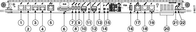
|
1 |
BITS 0 |
12 |
Control Ethernet 1 port (SFP or SFP+) |
|---|---|---|---|
|
2 |
BITS 1 |
13 |
Link/Active 1 LED |
|
3 |
DTI 0 |
14 |
OIR push button—Press to initiate OIR process |
|
4 |
DTI 1 |
15 |
OIR Ready LED |
|
5 |
Management Ethernet RJ45 port |
16 |
USB socket |
|
6 |
Alarm connector |
17 |
Service Ethernet RJ45 port |
|
7 |
Critical Alarm LED |
18 |
Console port |
|
8 |
Major Alarm LED |
19 |
Auxiliary port |
|
9 |
Minor Alarm LED |
20 |
Alphanumeric LED Display |
|
10 |
Control Ethernet 0 port (SFP or SFP+) |
21 |
PRIMARY LED—PRP active or standby indicator |
|
11 |
Link/Active 0 LED |
22 |
STATUS LED—Card status indicator |
Understanding the Alphanumeric LEDs
At one end of the faceplate, near an ejector lever, an RP, PRP, or DRP card has an alphanumeric LED display that shows a sequence of messages indicating the state of the card.
Note | It is normal for some displayed messages to appear too briefly in the LED display to be read. |
Troubleshooting the RP, PRP, or DRP Card
If the installed or replaced card fails to operate or to power up on installation, do the following:
- Make sure that the card is seated firmly in the Cisco CRS 8-Slot Line Card Chassis Enhanced router slot. One easy way to verify physical installation is to see whether the front faceplate of the card is even with the fronts of the other cards installed in the card cage.
Note | PRP cards only—If the PRP is not seated properly, the blue OIR Ready LED on the faceplate glows solidly, and the Primary and Status LEDs keep blinking to indicate that the card is not seated correctly. If this happens, remove the card fully and re-insert fully. |
- Check whether the ejector levers are latched and that the captive screws are fastened properly. If you are uncertain, unlatch the levers, loosen the screws, and attempt to reseat the card.
- Examine the alarm LEDs on the to see if there are any active alarm conditions.
- Examine the power shelves to see whether the chassis, as a whole, is receiving power.
Status LEDs
Use the status LEDs, located on the card faceplate, to verify the correct installation of the card:
- When the card is properly installed, the Status LED turns green. If this LED is off, verify that the card is installed correctly.
- When the Status LED is blinking yellow, a problem exists on the board.
- When the Status LED is off, the board state is unknown. Verify that there is power to the board by looking at the indicators on the power module.
- When the Primary LED is on, the board is executing control processing functions and is not in a secondary or standby role.
- If there is a failure during the board boot sequence, the four-row, four-character alphanumeric display indicates the current boot phase to assist you in debugging the board failure.
Installing a Switch Fabric Card
This section contains the following procedures:
Installing a Switch Fabric Card
This section describes how to install a switch fabric card in the Cisco CRS 8-Slot Line Card Chassis Enhanced router.
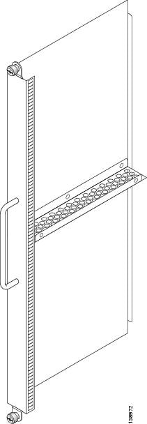
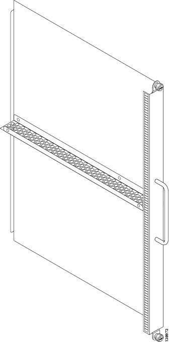
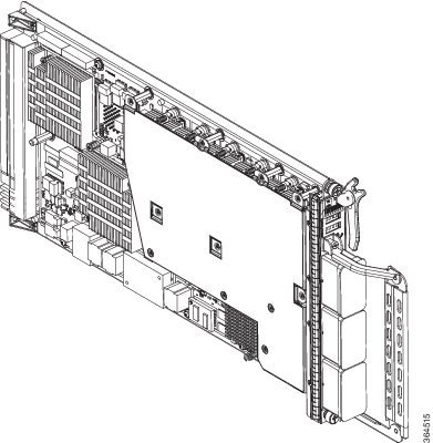
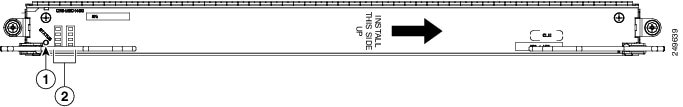
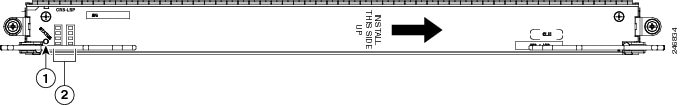
Depending on the card, the fabric card can be used in a CRS single-chassis system or a CRS back-to-back system. #con_1217629/fig_1448477 shows the single-chassis fabric card (CRS-8-FC400/S). #con_1217629/fig_1439309 shows the back-back fabric card (CRS-8-FC400/M).
Prerequisites
Before performing this task, remove any switch fabric card or switch fabric impedance cover from the slot in which you plan on installing the switch fabric card. See About Impedance Carriers and Slot Covers and Removing a Switch Fabric Card, page 7-4 .
Caution | Removing more than one switch fabric card at a time can misalign the chassis and may damage the card or chassis when reinserting the cards. Remove and reinsert only one card at a time. |
Required Tools and Equipment
You need the following tools and part to perform this task:
- ESD-preventive wrist strap
- Number 2 Phillips or number 2 common (flat-head) screwdriver
- Switch fabric card
Steps
Caution | For a CRS back-to-back installation, do not remove the dust caps from the three bulkhead connectors until the fiber bundle is connected to the port or connector. After installation, retain and store the dust caps in a clearn, dust-free area. For more information, see Cabling the CRS Back-to-Back System . |
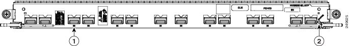
To install a switch fabric card, see #task_1440875/fig_1343030 and follow these steps:
|
1 |
Captive screw |
3 |
Direction of installation or removal |
|
2 |
Ejector lever |
|
|
| Step 1 | Attach the ESD-preventive wrist strap to your wrist and connect its leash to an ESD connection socket on the rear (MSC) side or a bare metal surface on the chassis. | ||
| Step 2 | Remove the switch fabric card from its antistatic packaging. | ||
| Step 3 | Visually inspect the connector pins on the card before you insert it into the chassis. Do not attempt to install a card with bent pins, as this may damage the chassis midplane connectors. | ||
| Step 4 | Grasp the card carrier handle with one hand and place your other hand under the carrier to support and guide it into the correct slot. | ||
| Step 5 | Position the
card for insertion into the card cage slot. Avoid touching the card circuitry
or any connectors.
| ||
| Step 6 | Orient the switch fabric card so that the PCB faces left and the carrier is to the right; if the card does not slide easily into the slot, the orientation may be wrong and the disorientation rejection flange is stopping the card from going in. Reorient the switch fabric card, if applicable. | ||
| Step 7 | Carefully slide
the switch fabric card into the slot until the ejector levers meet the edges of
the card cage, then
stop when
the ejector lever hooks catch the lip of the card cage. If they do not catch,
try reinserting the switch fabric card until the ejector lever hooks are fully
latched.
| ||
| Step 8 | Pivot both card
ejector levers so that the openings on the card ejector cams at the top and
bottom of the card pass over the tabs on each side of the card cage slot.
| ||
| Step 9 | Continue
sliding the card into the card cage slot until the openings on the card ejector
cams engage the tabs on each side of the card cage slot.
| ||
| Step 10 | To seat the
card in the midplane connector, grasp both card ejector levers and pivot them
inward toward the handle in the card carrier until they are flush against the
front edge of the card carrier.
| ||
| Step 11 | Partially tighten the two captive screws on the front panel of the card (either by hand or with the screwdriver) to make sure that they are both engaged. | ||
| Step 12 | Use the screwdriver to fully tighten the captive screws to seat the card firmly in the slot. |
What to Do Next
After performing this task, verify that the card has been installed properly (see Verifying the Installation of a Switch Fabric Card). If you are performing the initial installation of the system, install the MSCs (see Installing an MSC, FP, or LSP).
Verifying the Installation of a Switch Fabric Card
This section describes how to verify that a switch fabric card has been properly installed. Figure 1 shows the switch fabric card front panel.
Understanding the Alphanumeric LEDs
At one end of the faceplate, near an ejector lever, a switch fabric card has an alphanumeric LED display that shows a sequence of messages indicating the state of the card.
Note | It is normal for some displayed messages to appear too briefly in the LED display to be read. |
Troubleshooting the Switch Fabric Card
If the installed or replaced switch fabric card fails to operate or to power up on installation:
- Make sure that the card is seated firmly in the Cisco CRS 8-Slot Line Card Chassis Enhanced router slot. One easy way to verify physical installation is to see whether the front faceplate of the switch fabric card is even with the fronts of the other cards installed in the card cage.
- Check whether the ejector levers are latched and that the captive screws are fastened properly. If you are uncertain, unlatch the levers, loosen the screws, and attempt to reseat the switch fabric card.
- Examine the alarm LEDs on the RP to see if there are any active alarm conditions.
- Examine the power shelves to see whether the chassis, as a whole, is receiving power.
Switch Fabric Card Status LEDs
Use the status LEDs, located on the switch fabric card faceplate, to verify the correct installation of the card:
- When the card is properly installed, the Status turns green. If this LED is off, verify that the card is installed correctly.
- When the Status is blinking yellow, a problem exists on the board.
- When the Status is off, the board state is unknown. Verify that there is power to the board by looking at the indicators on the power module.
- If there is a failure during the board boot sequence, the two-row, four-character alphanumeric display indicates the current boot phase to assist you in debugging the board failure.
Installing an MSC, FP, or LSP
Note | The following line cards are only supported if the new fan-tray (CRS-8-FANTRAY-B) is in use: CRS-MSC-X, CRS-FP-X, and CRS-LSP-X. For more details, see Upgrading Fan Trays, page 4-8 . |
This section contains the following procedures:
Installing an MSC, FP, or LSP
This section describes how to install an MSC, FP, or LSP line card in the Cisco CRS 8-Slot Line Card Chassis Enhanced router.
The MSC, FP, and LSP line cards are Layer 3 forwarding engines in the Cisco CRS Series routing system. A line card can be paired with different types of physical layer interface modules (PLIMs) to provide a variety of interfaces.
- The MSCs include: CRS-MSC, CRS-MSC-B, CRS-MSC-140G, CRS-FP-X/ CRS-FP-X-L(400G).
- The FPs include: CRS-FP-140, CRS-FP-X/ CRS-FP-X-L (400G).
- The LSPs include: CRS-LSP, CRS-LSP-X (400G).
A line card fits into any available MSC slot and connects directly to the midplane. If you install a new line card, you must first remove the MSC impedance carrier from the available slot.
Caution | Be careful while handing these line cards to avoid pressing the memory module latches on the daughter board and accidently disengaging the memory modules. For the location of these latches, see the following figure. |
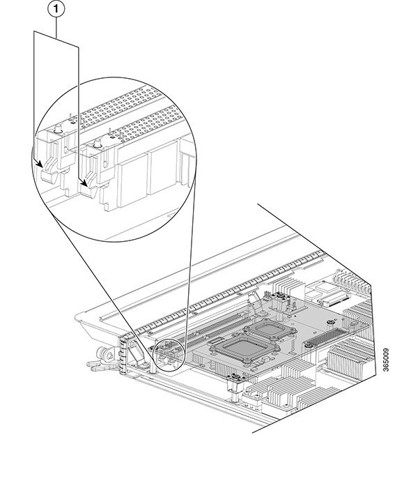
|
1 |
Memory Module Latches |
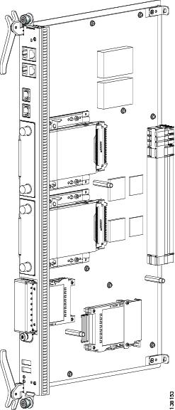
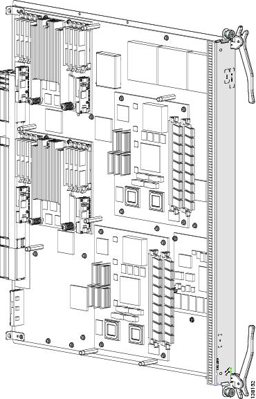
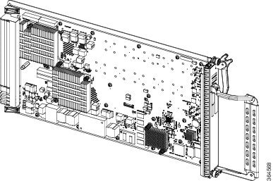
The following figure shows the CRS-MSC-140G MSC. The other MSC, FP, and LSP cards are similar.
Prerequisites
Note | See Chapter 2, “Chassis Overview,” for information on MSC slot types, numbers, widths, and locations. |
Caution | Remove or install only one line card at a time. Allow at least 15 seconds for the router to complete the preceding tasks before removing or installing another line card. The router may indicate a hardware failure if you do not follow proper procedures. |
Caution | Do not carry an MSC by the bracket attached to the faceplate. |
Required Tools and Equipment
You need the following tools and part to perform this task:
- ESD-preventive strap
- Number 2 Phillips or number 2 common (flat-head) screwdriver
- MSC, FP, or LSP line card (see the product data sheet for ordering details).
Steps
To install a line card, follow these steps:
|
1 |
Captive screw |
3 |
Direction of installation or removal |
|
2 |
Ejector lever |
|
|
| Step 1 | Attach the ESD-preventive wrist strap to your wrist and connect its leash to an ESD connection socket on the rear (MSC) side or a bare metal surface on the chassis. | ||
| Step 2 | Choose an
available MSC slot for the MSC.
| ||
| Step 3 | Remove the MSC
impedance carrier from the slot you need to fill and set it aside.
| ||
| Step 4 | Remove the line card you are installing from its antistatic packaging. | ||
| Step 5 | Visually inspect the connector on the card before you insert it into the chassis. Do not attempt to install a card with a damaged connector, as this action may damage the chassis midplane pins. | ||
| Step 6 | Use both hands while inserting an line card. Use one hand on the faceplate and the other hand along the base of the line card to guide it into a slot. | ||
| Step 7 | Orient the line card so that the PCB faces left and the carrier is to the right; if the card does not slide easily into the slot, the orientation may be wrong and the misorientation rejection flange is stopping the card from going into the slot. Reorient the line card, if applicable. | ||
| Step 8 | Make sure that the ejector levers are oriented properly to engage with the pin as the line card slides into the slot. Carefully slide the line card into the slot until the ejector levers engage the catches, then stop. | ||
| Step 9 | Simultaneously
pivot the ejector levers toward the faceplate of the line card. Do not force
the line card; the ejector levers properly seat the line card against the
midplane.
| ||
| Step 10 | Partially tighten the two captive screws on the front panel of the card (either by hand or with the screwdriver) to make sure that they are both engaged. | ||
| Step 11 | Use a
screwdriver to fully tighten the captive screws next to each line card ejector
lever to ensure proper EMI shielding and to prevent the card from becoming
partially dislodged from the midplane.
| ||
| Step 12 | Attach the bracket to the line card; use the screws that came with it. |
What to Do Next
After performing this task, verify that the card has been installed properly (see Verifying the Installation of an MSC, FP, or LSP). If you are performing the initial installation of the system, install the PLIMs (see Installing a Physical Layer Interface Module).
Verifying the Installation of an MSC, FP, or LSP
This section describes how to verify that a line card has been properly installed.
The following figure is an illustration of the MSC-140G front panel.
|
1 |
Status LED |
2 |
Alphanumeric LEDs |
The following figure shows the FP-140 FP face panel.

|
1 |
Status LED |
2 |
Alphanumeric LEDs |
The following figure shows the CRS-LSP front panel.
|
1 |
Status LED |
2 |
Alphanumeric LEDs |
Understanding the Alphanumeric LEDs
At one end of the faceplate, near an ejector lever, a line card has two four-digit alphanumeric LED displays that show a sequence of messages indicating the state of the card.
Note | It is normal for some displayed messages to appear too briefly in the LED display to be read. |
Troubleshooting the MSC, FP, or LSP
If the installed or replaced line card fails to operate or to power up on installation:
- Make sure that the card is seated firmly in the Cisco CRS 8-Slot Line Card Chassis Enhanced router slot. One easy way to verify physical installation is to see whether the front faceplate of the MSC is even with the fronts of the other cards installed in the card cage.
- Check whether the ejector levers are latched and that the captive screws are fastened properly. If you are uncertain, unlatch the levers, loosen the screws, and attempt to reseat the MSC.
- Examine the Cisco CRS 8-Slot Line Card Chassis Enhanced router alarm LEDs on the RP to see if there are any active alarm conditions.
- Examine the Cisco CRS 8-Slot Line Card Chassis Enhanced router power distribution units (PDUs) to see whether the chassis, as a whole, is receiving power.
Status LEDs
Use the status LEDs, located on the line card faceplate, to verify the correct installation of the card:
- When the card is properly installed, the Status LED turns green. If this LED is off, verify that the card is installed correctly.
- When the Status LED is blinking yellow, a problem exists on the board.
- When the Status LED is off, the board state is unknown. Verify that there is power to the board by looking at the indicators on the power module.
Installing a Physical Layer Interface Module
This section contains the following procedures:
Installing a PLIM
This section describes how to install a PLIM in the Cisco CRS 8-Slot Line Card Chassis Enhanced router.
A physical layer interface module (PLIM) is paired with an MSC through the midplane of the chassis. A PLIM provides the ability to choose several interfaces.
Caution | The system may indicate a hardware failure if you do not follow proper procedures. Remove or install only one PLIM at a time. Allow at least 15 seconds for the system to complete the preceding tasks before removing or installing another PLIM. |
Prerequisites
Before performing this task, remove the front cover, if installed.
Required Tools and Equipment
You need the following tools and part to perform this task:
- ESD-preventive wrist strap
- Number 2 Phillips or number 2 common (flat-head) screwdriver
- PLIM
Steps
To install a PLIM, follow these steps:
What to Do Next
Because invisible
laser radiation may be emitted from the aperture of the port when no cable is
connected, avoid exposure to laser radiation and do not stare into open
apertures. Statement 70
Some PLIMs contain Class 1 lasers, and some contain Class 1M. See the documentation for the specific PLIM for details.
What to Do Next
After performing this task, reinstall the front cover, if applicable, and verify that the PLIM has been installed properly (see Verifying the Installation of a PLIM).
Verifying the Installation of a PLIM
This section describes how to verify that the PLIM has been properly installed.
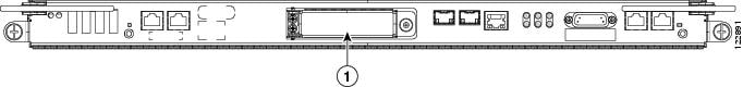
The following figure shows the PLIM front panel (in this case, a 14-port 10-GE XFP PLIM).
|
1 |
Port LED (one per port) |
2 |
Status LED |
Troubleshooting the PLIM
If the installed or replaced PLIM fails to operate or to power up on installation:
- Make sure that the PLIM is seated firmly in the Cisco CRS 8-Slot Line Card Chassis Enhanced router slot. One easy way to verify physical installation is to see whether the front faceplate of the PLIM is even with the fronts of the other PLIMs installed in the card cage.
- Check whether the ejector levers are latched and that the captive screws are fastened properly. If you are uncertain, unlatch the levers, loosen the screws, and attempt to reseat the PLIM.
- Examine the alarm LEDs on the RP to see if there are any active alarm conditions.
- Examine the power shelves to see whether the chassis, as a whole, is receiving power.
Use the status LEDs, located on the PLIM faceplate, to verify the correct installation of the card:
There are two types of LEDs on a PLIM: the board-level LED labeled Status and the port-level LEDs that are labeled differently depending on the PLIM type. When the PLIM is properly installed, the Status LED turns green. If this LED is off, verify that the associated MSC, FP, or LSP line card is installed correctly. For details on the information provided by the port-level LEDs, see the documentation specific to that PLIM.
Installing a PCMCIA Card
This section describes how to install a PCMCIA card in an RP or a DRP card PCMCIA slot. For more detailed information on PCMCIA cards, see About Hard Drives and PCMCIA Cards. The following figure shows you the location of the PCMCIA door in the RP card faceplate. (The PCMCIA cards for the DRP are in a similar location.)
Note | Only disk1: can be installed in or removed from the Cisco CRS 8-Slot Line Card Chassis Enhanced router Route Processor. |
1 - PCMCIA flip-up door
Note | Only the original route processor (RP) card uses a PCMCIA card. The performance route processor (PRP) card has a USB connector for using a flash drive. |
Prerequisites
Before performing this task, remove the front cover, if installed. If you are replacing a PCMCIA card, see Removing an RP PCMCIA Card, page 7-12 to remove the PCMCIA card from the PCMCIA card slot.
Required Tools and Equipment
You need the following tools and part to perform this task:
- ESD-preventive strap
- Number 2 Phillips or number 2 common (flat-head) screwdriver
- PCMCIA card
Steps
To install a PCMCIA card, follow these steps:
| Step 1 | Attach the ESD-preventive wrist strap to your wrist and connect its leash to an ESD connection socket on the front (PLIM) side or a bare metal surface on the chassis. |
| Step 2 | Using the screwdriver, loosen the captive screw at the bottom of the PCMCIA slot door on the faceplate of the card. |
| Step 3 |
While lifting the hinged PCMCIA slot door up, carefully insert the new PCMCIA flash card into the left slot of the PCMCIA card cage.
When the card is fully inserted, the release button pops up. (If the button fails to pop up, you may not have the card in right side up; turn the card over and try again.) |
| Step 4 | Close the door to keep dust out, and tighten the captive screw. |
What to Do Next
After performing this task, replace the front cover, if applicable.
Installing a Small Form-Factor Pluggable (SFP) Module
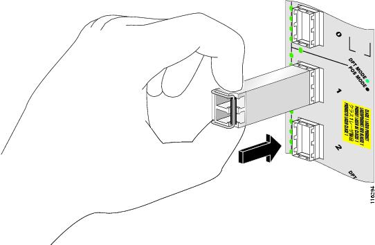
This section describes how to install a bale-clasp SFP module. The module has a clasp used to install and remove the module .
For general information about SFP modules, see About Small Form-Factor Pluggable (SFP) Modules. For information on SFP optical cleaning, see “Inspection and Cleaning Procedures for Fiber-Optic Connections,” at the following URL:
http://www.cisco.com/warp/public/127/cleanfiber2.html
Because invisible laser radiation may be emitted from the aperture of the port when no cable is connected, avoid exposure to laser radiation and do not stare into open apertures. Statement 70
Prerequisites
Before installing a module, remove the front cover, if installed.
Required Tools and Equipment
You need the following tools and part to perform this task:
- ESD-preventive wrist strap
- Bale-clasp SFP module
Steps
To install a bale-clasp SFP module (into a PLIM), follow these steps:
| Step 1 | Attach the ESD-preventive wrist strap to your wrist and connect its leash to an ESD connection socket on the front (PLIM) side or a bare metal surface on the chassis. | ||
| Step 2 | Close the bale clasp before inserting the module. | ||
| Step 3 | Align the
module with the port and slide it into the port .
 |
What to Do Next
After performing this task, replace the front cover, if applicable.
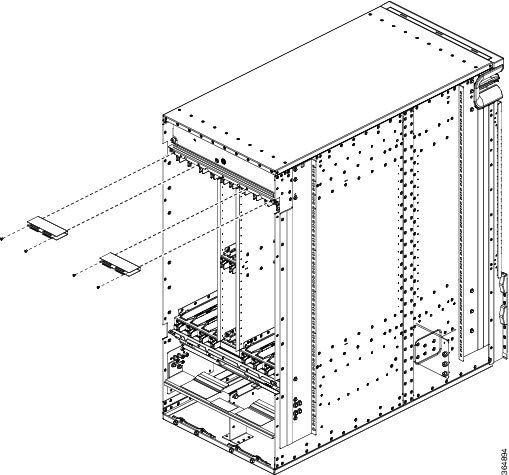
Installing the Front Cable Management Bracket
This section shows how to install the front Cable Management Bracket. The following figure displays a front cable management bracket.
Prerequisites
Be sure that no cables impede your access to the area of the chassis on which you wish to install the bracket.
Before installing a front cable management bracket on the front (PLIM) side of the chassis, remove the front cover and inlet grille, if installed.
Required Tools and Equipment
You need the following tools and parts to perform this task:
- ESD-preventive wrist strap
- 6-in. long number 1 Phillips screwdriver
- Medium flat-blade screwdriver
- Cable management bracket
Steps
To install a cable management bracket, follow these steps:
| Step 1 | Attach the ESD-preventive wrist strap to your wrist and connect its leash to an ESD connection socket or a bare metal surface on the chassis. | ||||
| Step 2 |
If applicable, remove the Cisco logo bezel from the front of the chassis. | ||||
| Step 3 | Position the front cable management bracket on the chassis. | ||||
| Step 4 |
Insert and tighten the four screws to secure the bracket to the chassis.
| ||||
| Step 5 | If applicable, reattach the logo bezel by snapping it back onto the front of the chassis. |
What to Do Next
Use the front cable management bracket to organize your cables. Then reinstall the inlet grille and front cover. See Installing the Front Side Exterior Components, page 5-1 for more information.
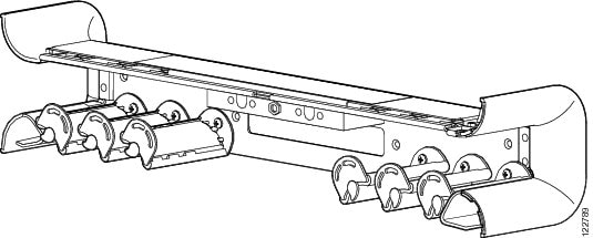
Installing the Rear Cable Management Bracket
This section shows how to install the rear Cable Management Bracket. The following figure displays a rear cable management bracket.
Prerequisites
Be sure that no cables impede your access to the area of the chassis on which you wish to install the bracket.
Required Tools and Equipment
You need the following tools and parts to perform this task:
- ESD-preventive wrist strap
- 6-in. long number 1 Phillips screwdriver
- Rear Cable management bracket
Steps
To install a rear cable management bracket, follow these steps:
| Step 1 | Attach the ESD-preventive wrist strap to your wrist and connect its leash to an ESD connection socket or a bare metal surface on the chassis. |
| Step 2 | Remove the two
screws from the chassis, where the bracket will be installed. The rear cable
management bracket does not come with screws as they are reused from the
chassis.
 |
| Step 3 | Position the rear cable management bracket on the chassis. |
| Step 4 | Insert and tighten the two screws to secure the bracket to the chassis. |
What to Do Next
Use the rear cable management bracket to organize your cables.
 Feedback